WO2012056614A1 - アーク溶接の制御システムおよび制御方法 - Google Patents
アーク溶接の制御システムおよび制御方法 Download PDFInfo
- Publication number
- WO2012056614A1 WO2012056614A1 PCT/JP2011/003872 JP2011003872W WO2012056614A1 WO 2012056614 A1 WO2012056614 A1 WO 2012056614A1 JP 2011003872 W JP2011003872 W JP 2011003872W WO 2012056614 A1 WO2012056614 A1 WO 2012056614A1
- Authority
- WO
- WIPO (PCT)
- Prior art keywords
- welding
- torch height
- deviation
- torch
- operation amount
- Prior art date
Links
Images


Classifications
-
- B—PERFORMING OPERATIONS; TRANSPORTING
- B23—MACHINE TOOLS; METAL-WORKING NOT OTHERWISE PROVIDED FOR
- B23K—SOLDERING OR UNSOLDERING; WELDING; CLADDING OR PLATING BY SOLDERING OR WELDING; CUTTING BY APPLYING HEAT LOCALLY, e.g. FLAME CUTTING; WORKING BY LASER BEAM
- B23K9/00—Arc welding or cutting
- B23K9/09—Arrangements or circuits for arc welding with pulsed current or voltage
-
- B—PERFORMING OPERATIONS; TRANSPORTING
- B23—MACHINE TOOLS; METAL-WORKING NOT OTHERWISE PROVIDED FOR
- B23K—SOLDERING OR UNSOLDERING; WELDING; CLADDING OR PLATING BY SOLDERING OR WELDING; CUTTING BY APPLYING HEAT LOCALLY, e.g. FLAME CUTTING; WORKING BY LASER BEAM
- B23K9/00—Arc welding or cutting
- B23K9/02—Seam welding; Backing means; Inserts
- B23K9/0216—Seam profiling, e.g. weaving, multilayer
-
- B—PERFORMING OPERATIONS; TRANSPORTING
- B23—MACHINE TOOLS; METAL-WORKING NOT OTHERWISE PROVIDED FOR
- B23K—SOLDERING OR UNSOLDERING; WELDING; CLADDING OR PLATING BY SOLDERING OR WELDING; CUTTING BY APPLYING HEAT LOCALLY, e.g. FLAME CUTTING; WORKING BY LASER BEAM
- B23K9/00—Arc welding or cutting
- B23K9/095—Monitoring or automatic control of welding parameters
- B23K9/0953—Monitoring or automatic control of welding parameters using computing means
-
- B—PERFORMING OPERATIONS; TRANSPORTING
- B23—MACHINE TOOLS; METAL-WORKING NOT OTHERWISE PROVIDED FOR
- B23K—SOLDERING OR UNSOLDERING; WELDING; CLADDING OR PLATING BY SOLDERING OR WELDING; CUTTING BY APPLYING HEAT LOCALLY, e.g. FLAME CUTTING; WORKING BY LASER BEAM
- B23K9/00—Arc welding or cutting
- B23K9/095—Monitoring or automatic control of welding parameters
- B23K9/0956—Monitoring or automatic control of welding parameters using sensing means, e.g. optical
-
- B—PERFORMING OPERATIONS; TRANSPORTING
- B23—MACHINE TOOLS; METAL-WORKING NOT OTHERWISE PROVIDED FOR
- B23K—SOLDERING OR UNSOLDERING; WELDING; CLADDING OR PLATING BY SOLDERING OR WELDING; CUTTING BY APPLYING HEAT LOCALLY, e.g. FLAME CUTTING; WORKING BY LASER BEAM
- B23K9/00—Arc welding or cutting
- B23K9/12—Automatic feeding or moving of electrodes or work for spot or seam welding or cutting
- B23K9/127—Means for tracking lines during arc welding or cutting
Definitions
- the present invention relates to an arc welding control system and control method for controlling the position of a welding torch in accordance with an arc current or voltage.
- the welding current or arc of the arc generated between the electrode protruding from the tip of the welding torch and the workpiece The position of the welding torch is grasped by detecting the voltage and calculating the distance between the tip of the electrode and the workpiece.
- the welding line scanning can be controlled by comparing the welding current value or arc voltage value at both ends of the weaving, and by comparing the welding current value or arc voltage value during weaving with the target value.
- the torch height can be controlled.
- control is performed to increase or decrease the weaving width by comparing the welding current value or arc voltage value at the end of the weaving with the target value.
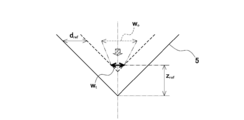
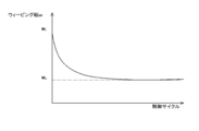
- FIG. 11A to 11C are schematic diagrams for explaining disadvantages in the conventional arc sensor weaving width control.
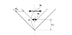
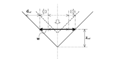
- the weaving width is such that the horizontal distance (wall distance) between the end of the weaving width w and the workpiece becomes the target value d ref.
- the control for widening w is performed and the control for decreasing the torch height z so that the torch height z becomes the target value z ref is performed, as shown in FIG. Since the horizontal distance between the end portion of the width and the workpiece is also shortened, the weaving width w becomes larger than the target weaving width w t at the target torch height z ref .
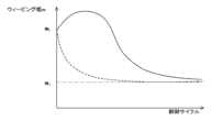
- the control of the weaving width and the torch height is changed little by little every predetermined control cycle. Therefore, with regard to the weaving width w, as shown by the broken line in FIG. 11C, it is desirable to gradually approach the target weaving width w t as the control cycle is repeated from the initial weaving width w 0 .
- the above conventional arrangement widening the initial weaving width w 0 weaving width w despite it is necessary to perform control for narrowing the weaving width w to approach the target weaving width w t would otherwise against Since control is performed, as shown by the solid line in FIG. 11C, it takes time to operate in the opposite direction to the target value or to stabilize at the target value.
- the present invention has been made to solve the above-described problems, and provides an arc welding control system and control method capable of simultaneously controlling the weaving width and the torch height with high performance.
- the purpose is to do.
- An arc welding control system is configured to periodically move a welding torch in a width direction of a groove of a workpiece to be welded with a predetermined weaving width at a predetermined torch height in the weld line direction of the workpiece.
- An arc for forming a good bead in the groove of the workpiece comprising an actuator for moving the welding torch to follow the welding line of the workpiece and a sensor for detecting a welding current or an arc voltage
- An arc sensor control system for welding which corresponds to a groove wall distance indicating a horizontal distance between the welding torch and the workpiece at the end of the weaving from the welding current or arc voltage, and the torch height.
- Each value is acquired, the difference from each target value is calculated, and the deviation of the value corresponding to the groove wall distance from the target value (hereinafter referred to as the opening value).
- An operation amount related to the weaving width of the actuator is calculated from a deviation from a target value (hereinafter referred to as a torch height deviation) of a value corresponding to the torch height, and a distance corresponding to the torch height.
- An arithmetic unit that calculates an operation amount related to the torch height of the actuator from a wall distance deviation and the torch height deviation, an operation amount related to the weaving width, and an operation amount related to the torch height, and the weaving width and the A controller for controlling the torch height, respectively, and the ratio of the groove wall distance deviation and the torch height deviation to the manipulation amount of the weaving width and the manipulation amount of the torch height, respectively (
- the influence ratio is set according to the groove angle of the workpiece, and the groove wall distance deviation and the torque
- the influence ratio of the torch height deviation is set such that the influence ratio of the torch height deviation is relatively larger than the influence ratio of the groove wall distance deviation as the groove angle is larger. ing.
- the operation amount may be obtained by multiplying the influence ratio by an adjustment coefficient for adjusting the influence ratio. Thereby, even if it is the same groove angle, it can adjust to more suitable control performance according to the kind and use application of a workpiece
- the operation amount ⁇ z of the torch height may be expressed by the following equation (1)
- the operation amount ⁇ w of the weaving width may be expressed by the following equation (2).
- K z, K w denotes the respective gains of the operation amount and the horizontal actuator operation amount of vertical actuators
- [Delta] P d represents the groove wall distance deviation
- [Delta] P h denotes the height of the torch deviation
- K h represents an adjustment coefficient.
- the computing unit calculates an average value of the welding current or arc voltage detected from the sensor for each of a plurality of sections obtained by dividing one period of weaving by a predetermined number, and the plurality of sections A value corresponding to the groove wall distance based on the average value of one or a plurality of sections corresponding to the end of the weaving, and the average value of the welding current or arc voltage for one cycle of weaving.
- a value corresponding to the torch height may be obtained based on the above.
- the arc sensor control method for arc welding includes a welding torch which is periodically moved in a width direction of a groove of a workpiece to be welded with a predetermined weaving width in a predetermined welding line direction of the workpiece.
- Arc welding for forming a bead at the groove of the workpiece comprising: an actuator for moving the welding torch at a height of the torch to follow the welding line of the workpiece; and a sensor for detecting a welding current or an arc voltage. And a step of detecting the welding current or arc voltage, and a groove wall distance indicating a horizontal distance between the welding torch and the workpiece at the end of the weaving from the welding current or arc voltage.
- Deviation of the value corresponding to the groove wall distance from the target value hereinafter referred to as groove wall distance deviation
- deviation of the value corresponding to the torch height from the target value hereinafter referred to as torch height deviation.
- the ratio that the groove wall distance deviation and the torch height deviation influence (hereinafter referred to as the influence ratio) is the workpiece.
- the influence ratio of the groove wall distance deviation and the torch height deviation is set according to the groove angle. The larger the groove angle, the larger the groove angle, the more the groove wall distance deviation influence ratio, the torch height.
- the influence ratio of the deviation is set to be relatively large.
- the influence ratio (weighting factor) of the parameters relating to the groove wall distance deviation and torch height deviation at each operation amount is set according to the groove angle of the workpiece. Then, after earnest research, the inventors have made the influence ratio of the torch height deviation relatively larger than the influence ratio of the groove wall distance deviation as the groove angle of the workpiece is larger at any operation amount. As a result, it has been found that the weaving width and the torch height can be quickly and optimally controlled without lowering the gain. Therefore, by controlling using the above method, weaving width control and torch height control can be performed simultaneously and with high performance.
- the present invention is configured as described above, and has an effect that the weaving width control and the torch height control can be performed simultaneously and with high performance.
- FIG. 1 It is a block diagram showing a schematic structure of a control system of arc welding concerning one embodiment of the present invention. It is a figure which shows the geometric shape model which modeled the positional relationship of the welding torch and workpiece
- FIG. It is a perspective view which shows the shape of the workpiece
- FIG. It is a figure which shows the arc voltage detected in the arc sensor control in Example 1.
- FIG. It is a figure which shows the deviation with respect to the target value of the weaving width
- FIG. It is a figure which shows the horizontal position locus
- FIG. It is a figure which shows the vertical position locus
- FIG. It is a figure which shows the time change of the weaving width
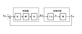
- FIG. 1 is a block diagram showing a schematic configuration of a welding system to which an arc welding arc sensor control system according to an embodiment of the present invention is applied.
- a welding system to which an arc welding arc sensor control system of this embodiment is applied includes a welding apparatus 1, an arithmetic controller 2 that controls the welding apparatus 1, and an arc generated in the welding apparatus 1. And a sensor 4 for detecting the arc welding current and arc voltage.
- the welding apparatus 1 has a welding torch 11 having a nozzle for supplying a shielding gas to the welded portion.
- An electrode 12 is provided at the tip (lower end) of the welding torch 11.
- a power line from the welding power source 3 is connected to the welding torch 11 and supplied with power.
- the welding apparatus 1 includes a horizontal actuator 13 that moves the welding torch 11 in the horizontal axis direction, and a vertical actuator 14 that moves the welding torch 11 in the vertical direction.
- the horizontal actuator 13 and the vertical actuator 14 operate based on a control signal from the arithmetic controller 2 to move the welding torch 11 in the horizontal direction and the vertical direction.
- such a structure may be comprised by the articulated robot provided with the welding torch 11 in the front-end
- the work 5 to be welded is placed below the welding torch 11.
- the workpiece 5 is arranged in a state where two materials to be welded are in contact with each other, and a groove 51 is formed at a position to be welded.
- the groove 51 is arranged so that each groove surface has a predetermined groove angle ⁇ in a state where two workpieces are abutted.
- the groove angle ⁇ means an angle formed when the surfaces extending the groove surfaces intersect each other because the vicinity of the contact portion between the workpieces may be a curved surface. .
- the welding power source 3 is configured such that the power line of the welding power source 3 is also connected to the workpiece 5. A voltage is applied between the welding torch 11 (electrode 12 thereof) and the workpiece 5 by the electric power supplied from the welding power source 3, and an arc is generated between the electrode 12 protruding from the tip of the welding torch 11 and the workpiece 5. appear. Thereby, the workpiece
- work 5 is welded and a bead is formed.
- a voltage sensor 41 for detecting an arc voltage of the welding current or the arc voltage is provided as the sensor 4. .
- a current sensor 42 provided on any one of the power lines is also provided as the sensor 4.
- the sensor 4 that detects the welding current or arc voltage includes both the voltage sensor 41 that detects the arc voltage value and the current sensor 42 that detects the welding current value. But you can.
- the welding current or arc voltage may be detected directly or indirectly from the welding current or arc voltage between the power lines from the welding power source 3.
- MIG welding, MAG welding, and CO2 welding are controlled by a current value
- TIG welding is controlled by a voltage value. Therefore, the configuration may be rearranged or used properly according to the type of welding.
- the arithmetic controller 2 corresponds to the groove wall distance indicating the horizontal distance between the welding torch 11 and the groove wall of the workpiece 5 at the end of the weaving from the arc voltage or the welding current when the welding torch follows the weld line. And a value corresponding to the torch height, respectively, and calculating a difference from each target value, a deviation of the value corresponding to the groove wall distance from the target value (groove wall distance deviation) and An operation amount related to the weaving width of the actuator (that is, an operation amount of the vertical actuator 14) is calculated from a deviation (torch height deviation) of a value corresponding to the torch height from the target value, and a groove wall distance deviation and It functions as a calculator 21 that calculates an operation amount related to the torch height of the actuator (ie, an operation amount of the horizontal actuator 13) from the torch height deviation.
- the arithmetic controller 2 functions as a controller 22 that controls the actuators 13 and 14 of the welding apparatus 1 based on the operation amount relating to the weaving width and the operation amount relating to the torch height.
- the arithmetic controller 2 that functions as the controller 22 of the present embodiment uses the welding torch 11 to be a groove 51 of the workpiece 5 to be welded based on the welding current or arc voltage detected by the sensor 4. Control is made so that a bead is formed in the groove 51 of the work 5 by moving it at a predetermined torch height in the welding line direction of the groove 51 of the work 5 while periodically moving in the width direction of the work 5 with a predetermined weaving width. To do.
- the arithmetic controller 2 may have any configuration as long as it has a processing function, and includes, for example, a micro controller, a CPU, an MPU, a PLC (programmable logic controller), a logic circuit, and the like.
- one arithmetic controller 2 is described as a configuration that functions as both the arithmetic unit 21 and the controller 22, but may be configured as a separate controller or arithmetic unit.
- the arithmetic controller 2 acquires a value corresponding to the groove wall distance and a value corresponding to the torch height from the welding current or arc voltage detected by the sensor 4.
- the horizontal distance between the welding torch 11 and the workpiece 5 at the end of the weaving and the average height of the welding torch 11 are calculated from the arc voltage.
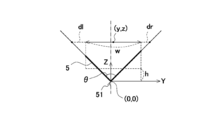
- FIG. 2 is a diagram showing a geometric shape model in which the positional relationship between the welding torch and the workpiece of the welding system shown in FIG. 1 is modeled.
- the Y axis is taken in the horizontal direction and the Z axis is taken in the vertical direction with the lower end of the groove 51 as the origin.
- the center coordinates of the weaving width w are (y, z), and these are used as control parameters.
- the horizontal distance between the left end of the weaving width w and the left wall of the workpiece 5 (the workpiece to be welded on the left side) is defined as dl, and the distance between the right end of the weaving width and the right wall of the workpiece 5 (the workpiece to be welded on the right side). Is the horizontal distance of dr, and the average vertical distance from the weaving position to the workpiece 5 is the average torch height h.
- the inventors of the present invention set the relationship between the above-mentioned parameters by the following equations after intensive research. That is, the weaving width w and the actual torch height z at the weaving center are set to be included at a predetermined ratio at any of the horizontal distances dl and dr and the average torch height h.
- the relational expression of each parameter at this time was set to the following expression.
- ⁇ y represents the operation amount for copying the welding line
- ⁇ z represents the operation amount for the torch height
- ⁇ w represents the operation amount for the weaving width
- the ratio that the torch height deviation influences at any operation amount is the ratio that the groove wall distance deviation affects as the groove angle ⁇ of the workpiece 5 is larger from the above expression (6). It was found that the weaving width w and the torch height z can be optimally controlled with high performance without lowering the gain by setting it to be relatively larger.
- V dref ⁇ (V dl + V dr ) / 2 indicates a groove wall distance deviation
- V href ⁇ V h indicates a torch height deviation
- K z, K w denotes the respective gains of the operation amount related to the torch height and weaving width
- K h denotes an adjustment factor
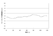
- FIG. 4 is a diagram showing the trajectory of the welding torch of the welding system shown in FIG. 1 and the corresponding arc voltage change.
- the upper diagram in FIG. 4 shows a graph of the torch trajectory, and the lower diagram in FIG. 4 shows a graph of the arc voltage change corresponding to the torch trajectory.
- the initial value is 0.
- the computing unit 21 calculates an average value of arc voltages detected from the sensor 4 for each of a plurality of sections obtained by dividing one period of weaving by a predetermined number, Among them, a value (voltage value) corresponding to the groove wall distance is acquired based on the average value of one or a plurality of sections corresponding to the calculated weaving end, and the average value of the arc voltage for one cycle of the weaving is obtained. Based on the torch height, a value (voltage value) corresponding to the torch height is acquired. Specifically, as shown in the lower diagram of FIG. 4, for example, one period of weaving is equally divided into eight sections (in the example of FIG. 4, eight sections 0 to 7 are divided into eight sections).
- the average arc voltage values in the sections 1 and 2 and sections 5 and 6) are used as the voltages V dl and V dr at the end of the weaving, and the entire average arc voltage value in one period of the weaving is a voltage V h indicating the torch height.
- the arc voltage at each position of the welding torch can be easily calculated.
- the arc voltage at the end of the weaving is detected by dividing one period of weaving into eight.
- the number of divisions is larger than this. May be less or less.
- the arc voltage at the end of the weaving may be a peak voltage value at the end of the weaving.
- the voltage at the center position of the weaving may be detected as a voltage indicating the voltage of the torch height.
- the distance between the tip of the wire serving as the electrode 12 and the workpiece falls within a predetermined distance, the arc is extinguished and short-circuiting time (short-circuiting time) is required. It becomes longer or the number of short circuits (number of short circuits) increases. Therefore, the distance between the tip of the wire and the workpiece may be estimated by measuring the short circuit time and the number of short circuits.
- a value corresponding to the groove wall distance and a value corresponding to the torch height are acquired by detecting an arc voltage in a predetermined section, and the voltage value itself is set as a target value (voltage value).
- the ratio of the groove wall deviation ⁇ P d and the torch height deviation ⁇ P h to the torch height manipulation amount ⁇ z and the weaving width manipulation amount ⁇ w (hereinafter referred to as influence).
- Ratio) is set according to the groove angle ⁇ of the workpiece 5. Specifically, the impact ratio is shown as the absolute value of the coefficient representing the weight of the groove wall distance deviation [Delta] P d and the torch height deviation [Delta] P h in the above equation (7) and (8).
- the calculator 21 increases the influence ratios ⁇ wh and ⁇ zh of the torch height deviation relative to the influence ratios ⁇ wd and ⁇ zd of the groove wall distance deviation as the groove angle ⁇ increases. Then, the operation amount ⁇ z of the torch height and the operation amount ⁇ w of the weaving width are calculated (so that the ratios ⁇ w and ⁇ z of the influence ratio are increased).
- the larger the groove angle ⁇ the greater the influence of the torch height deviation ⁇ P h than the influence of the groove wall distance deviation ⁇ P d at any operation amount ⁇ z, ⁇ w (the ratio of influence ratios ⁇ w , ⁇ z Will increase in size).
- the controller 22 controls the horizontal and vertical actuators 13 and 14 to move the welding torch 11 based on the operation amounts calculated by the calculator 21.
- An operation amount ⁇ w related to the width is calculated.
- the influence ratio (weighting factor) multiplied by the parameters related to the groove wall distance deviation ⁇ P d and the torch height deviation ⁇ P h at each operation amount is set according to the groove angle ⁇ of the workpiece 5.
- the gain is lowered by setting the influence ratio of the torch height deviation ⁇ P h to be larger than the influence ratio of the groove wall distance deviation ⁇ P d as the groove angle ⁇ of the work 5 is larger at any operation amount.
- the weaving width w and the torch height z can be controlled quickly and optimally. Therefore, by introducing such a control model, weaving width control and torch height control can be performed simultaneously and with high performance.
- FIGS. 11A and 11C are schematic diagrams conceptually showing the welding torch control of the welding system shown in FIG. 5A and 5B are diagrams corresponding to FIGS. 11A and 11C showing a conventional example.
- the welding torch 11 and the workpiece 5 can be prevented from abnormally approaching each other.
- the initial weaving width w 0 can be made asymptotic from the target weaving width w t in a short control cycle.
- each operation amount adjustment factor K h to adjust the effect ratio influences the ratio is multiplied. Thereby, even if it is the same groove angle (theta), according to the kind and use application of the workpiece
- arc sensor control is generally performed using a welding current, and therefore, a detection value for calculating an operation amount is preferably set to a welding current value, for example, TIG welding.
- arc sensor control is generally performed using an arc voltage, and it is preferable that the detected value for calculating the manipulated variable is also the arc voltage value.
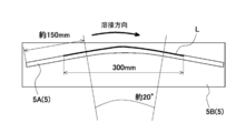
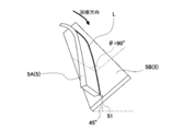
- FIG. 6A and 6B are diagrams showing the shape of the workpiece used in the first embodiment.
- 6A is a side view
- FIG. 6B is a perspective view.
- the side surface perpendicular to the short axis of the steel plate 5A having a shape in which the plate surface is curved around the short direction axis at the center in the longitudinal direction as the work 5 is inclined by 45 °.
- the welding line L turns to the left in the traveling direction while the welding torch 11 goes up, and turns to the right in the moving direction while going down the center part. Go.
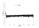
- 7A, 7B, 8A and 8B show the results of actual welding operations performed under the above conditions.
- 7A, 7B, 8A, and 8B are diagrams illustrating the results of arc sensor control in the first embodiment.
- 7A is a diagram showing the detected arc voltage
- FIG. 7B is a diagram showing a deviation of the weaving width with respect to the target value
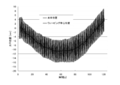
- FIG. 8A is a diagram showing a horizontal position trajectory of the welding torch
- FIG. 8B is a welding torch.
- FIG. 8A and 8B the initial value is set to 0 in both figures.
- the curve of the weld line could be copied with high performance in both the horizontal position related to the weld line copy and the vertical position related to the torch height control.
- the welding line L rises in the first half of welding, and the welding torch tends to move horizontally, so that the relative distance between the welding torch 11 and the workpiece 5 approaches,
- the weaving width is relatively small. This can also be confirmed by the horizontal position and amplitude in the first half of FIG. 8A.
- the welding line L goes down and the welding torch tries to move horizontally, so that the relative distance between the welding torch 11 and the workpiece 5 is increased, so that the weaving width is as shown in FIG. 7B. It is relatively large. This can also be confirmed by the horizontal position and amplitude in the latter half of FIG. 8B. Thus, it was shown that arc welding was performed faithfully according to the shape of the workpiece 5.
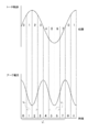
- FIG. 9A, 9B, 10A, and 10B show the results of actual welding operations performed under the above conditions.
- 9A, 9B, 10A, and 10B are diagrams showing the results of arc sensor control in Example 2 and the comparative example.
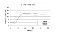
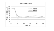
- FIG. 9A is a diagram showing the time change of the weaving width
- FIG. 9B is a diagram showing the time change of the horizontal distance between the weaving end and the workpiece
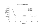
- FIG. 10A is a diagram showing the time change of the central torch height.
- FIG. 10B is a diagram showing the change over time of the average torch height.
- the weaving width overshoots immediately after the start of control. That is, as shown in FIG. 9B, the horizontal distance between the welding torch 11 and the workpiece 5 is abnormally close. Such an abnormal approach causes a welding defect such as an undercut.
- the weaving width is controlled smoothly without overshoot, there is no fear of welding defects as in the comparative example, and the weaving width is stable after a predetermined time. ing.
- the torch height as shown in FIGS. 10A and 10B, in the comparative example, the torch height overshoots immediately after the start of control, whereas in the embodiment, smooth and stable control is performed. Yes.
- the convergence of the weaving width and the torch height to the target values can be quickly performed without overshooting.
- control system and control method for arc welding according to the present invention are useful for performing the weaving width control and the torch height control simultaneously and with high performance.
Landscapes
- Engineering & Computer Science (AREA)
- Physics & Mathematics (AREA)
- Plasma & Fusion (AREA)
- Mechanical Engineering (AREA)
- Theoretical Computer Science (AREA)
- Butt Welding And Welding Of Specific Article (AREA)
- Arc Welding In General (AREA)
Abstract
Description


2 演算制御器
3 溶接電源
4 センサ
5 ワーク
11 溶接トーチ
12 電極
13 水平アクチュエータ
14 鉛直アクチュエータ
21 演算器
22 制御器
41 電圧センサ
42 電流センサ
51 開先
θ 開先角度
Claims (5)
- 溶接トーチを溶接対象であるワークの開先の幅方向に所定のウィービング幅で周期的に移動させつつ前記ワークの溶接線方向に所定のトーチ高さで前記溶接トーチを移動させて前記ワークの溶接線を倣わせるアクチュエータと、溶接電流またはアーク電圧を検出するセンサとを備え、前記ワークの開先に良好なビードを形成するためのアーク溶接のアークセンサ制御システムであって、
前記溶接電流またはアーク電圧からウィービングの端部における前記溶接トーチと前記ワークとの水平距離を示す開先壁距離に相当する値および前記トーチ高さに相当する値をそれぞれ取得し、それぞれの目標値との差をそれぞれ演算し、前記開先壁距離に相当する値のその目標値からの偏差(以下、開先壁距離偏差という)と前記トーチ高さに相当する値のその目標値からの偏差(以下、トーチ高さ偏差という)とから前記アクチュエータの前記ウィービング幅に関する操作量を演算するとともに、前記開先壁距離偏差と前記トーチ高さ偏差とから前記アクチュエータの前記トーチ高さに関する操作量を演算する演算器と、
前記ウィービング幅に関する操作量および前記トーチ高さに関する操作量に基づいて前記ウィービング幅および前記トーチ高さをそれぞれ制御する制御器と、を有し、
前記ウィービング幅の操作量および前記トーチ高さの操作量に対し、それぞれ前記開先壁距離偏差および前記トーチ高さ偏差が影響する比率(以下、影響比率という)が前記ワークの開先角度に応じて設定されており、
前記開先壁距離偏差および前記トーチ高さ偏差の影響比率は、前記開先角度が大きいほど前記開先壁距離偏差の影響比率に対し前記トーチ高さ偏差の影響比率が相対的に大きくなるように設定されている、アーク溶接のアークセンサ制御システム。 - 前記操作量は、前記影響比率に当該影響比率を調整する調整係数が掛けられている、請求項1に記載のアーク溶接の制御システム。
- 前記トーチ高さの操作量Δzは、次式(1)で表され、前記ウィービング幅の操作量Δwは、次式(2)で表される、請求項2に記載のアーク溶接の制御システム。


- 前記演算器は、ウィービングの1周期が予め定められた数で分割された複数の区間ごとに、前記センサから検出される前記溶接電流またはアーク電圧の平均値を算出し、前記複数の区間のうち、ウィービングの端部に対応する1または複数の区間の平均値に基づいて前記開先壁距離に相当する値を取得し、ウィービングの1周期分の前記溶接電流またはアーク電圧の平均値に基づいて前記トーチ高さに相当する値を取得する、請求項1に記載のアーク溶接の制御システム。
- 溶接トーチを溶接対象であるワークの開先の幅方向に所定のウィービング幅で周期的に移動させつつ前記ワークの溶接線方向に所定のトーチ高さで前記溶接トーチを移動させて前記ワークの溶接線を倣わせるアクチュエータと、溶接電流またはアーク電圧を検出するセンサとを備え、前記ワークの開先にビードを形成するためのアーク溶接のアークセンサ制御方法であって、
前記溶接電流またはアーク電圧を検出するステップと、
前記溶接電流またはアーク電圧からウィービングの端部における前記溶接トーチと前記ワークとの水平距離を示す開先壁距離に相当する値および前記トーチ高さに相当する値をそれぞれ取得し、それぞれの目標値との差をそれぞれ演算するステップと、
前記開先壁距離に相当する値のその目標値からの偏差(以下、開先壁距離偏差という)と前記トーチ高さに相当する値のその目標値からの偏差(以下、トーチ高さ偏差という)とから前記アクチュエータの前記ウィービング幅に関する操作量を演算するとともに、前記開先壁距離偏差と前記トーチ高さ偏差とから前記アクチュエータの前記トーチ高さに関する操作量を演算するステップと、
前記ウィービング幅に関する操作量および前記トーチ高さに関する操作量に基づいて前記ウィービング幅および前記トーチ高さをそれぞれ制御するステップと、を含み、
前記ウィービング幅の操作量および前記トーチ高さの操作量に対し、それぞれ前記開先壁距離偏差および前記トーチ高さ偏差が影響する比率(以下、影響比率という)が前記ワークの開先角度に応じて設定されており、
前記開先壁距離偏差および前記トーチ高さ偏差の影響比率は、前記開先角度が大きいほど前記開先壁距離偏差の影響比率に対し前記トーチ高さ偏差の影響比率が相対的に大きくなるように設定されている、アーク溶接の制御方法。
Priority Applications (4)
| Application Number | Priority Date | Filing Date | Title |
|---|---|---|---|
| US13/881,096 US9468987B2 (en) | 2010-10-26 | 2011-07-06 | Arc welding control system and method |
| CN201180046370.3A CN103124612B (zh) | 2010-10-26 | 2011-07-06 | 电弧焊接的控制系统及控制方法 |
| KR1020137007689A KR101386741B1 (ko) | 2010-10-26 | 2011-07-06 | 아크 용접의 제어시스템 및 제어방법 |
| US14/962,767 US10144081B2 (en) | 2010-10-26 | 2015-12-08 | Arc welding control system and method |
Applications Claiming Priority (2)
| Application Number | Priority Date | Filing Date | Title |
|---|---|---|---|
| JP2010240089A JP5538181B2 (ja) | 2010-10-26 | 2010-10-26 | アーク溶接の制御システムおよび制御方法 |
| JP2010-240089 | 2010-10-26 |
Related Child Applications (2)
| Application Number | Title | Priority Date | Filing Date |
|---|---|---|---|
| US13/881,096 A-371-Of-International US9468987B2 (en) | 2010-10-26 | 2011-07-06 | Arc welding control system and method |
| US14/962,767 Division US10144081B2 (en) | 2010-10-26 | 2015-12-08 | Arc welding control system and method |
Publications (1)
| Publication Number | Publication Date |
|---|---|
| WO2012056614A1 true WO2012056614A1 (ja) | 2012-05-03 |
Family
ID=45993363
Family Applications (1)
| Application Number | Title | Priority Date | Filing Date |
|---|---|---|---|
| PCT/JP2011/003872 WO2012056614A1 (ja) | 2010-10-26 | 2011-07-06 | アーク溶接の制御システムおよび制御方法 |
Country Status (5)
| Country | Link |
|---|---|
| US (2) | US9468987B2 (ja) |
| JP (1) | JP5538181B2 (ja) |
| KR (1) | KR101386741B1 (ja) |
| CN (1) | CN103124612B (ja) |
| WO (1) | WO2012056614A1 (ja) |
Cited By (2)
| Publication number | Priority date | Publication date | Assignee | Title |
|---|---|---|---|---|
| CN104493332A (zh) * | 2014-11-05 | 2015-04-08 | 湘潭大学 | 一种基于电弧摆动自调节传感机构的焊缝跟踪控制方法 |
| CN111266710A (zh) * | 2020-03-23 | 2020-06-12 | 昆山安意源管道科技有限公司 | 钨极惰性气体保护焊接方法 |
Families Citing this family (17)
| Publication number | Priority date | Publication date | Assignee | Title |
|---|---|---|---|---|
| KR101473639B1 (ko) * | 2013-02-25 | 2014-12-17 | 대우조선해양 주식회사 | 수평 맞대기 이음 대용착 용접 장치 및 그 방법 |
| US9962785B2 (en) * | 2013-12-12 | 2018-05-08 | Lincoln Global, Inc. | System and method for true electrode speed |
| US20160346867A1 (en) * | 2014-02-11 | 2016-12-01 | John Hill | Method Of Joining Dissimilar Materials |
| US10665128B2 (en) * | 2014-06-27 | 2020-05-26 | Illinois Tool Works Inc. | System and method of monitoring welding information |
| EP3165314A1 (de) * | 2015-11-06 | 2017-05-10 | Siegfried Plasch | Auftragsschweissverfahren |
| CN105665885B (zh) * | 2016-04-07 | 2018-05-25 | 湘潭大学 | 一种自适应调节焊枪倾角的立焊焊缝跟踪方法 |
| JP6794596B2 (ja) * | 2016-07-04 | 2020-12-02 | 株式会社神戸製鋼所 | 下向き溶接における溶接条件作成方法 |
| US11235414B2 (en) * | 2016-11-16 | 2022-02-01 | Kobe Steel, Ltd. | Method of detecting amount of discrepancy in arc tracking welding |
| JP6367985B2 (ja) | 2017-01-26 | 2018-08-01 | ファナック株式会社 | アークセンサ調整装置、及びアークセンサ調整方法 |
| CN108037665B (zh) * | 2017-12-13 | 2020-07-03 | 唐山松下产业机器有限公司 | 短路过渡状态的电弧自适应控制方法 |
| CN110434429A (zh) * | 2018-05-03 | 2019-11-12 | 天津大学 | 一种基于人机交互的机器人多层多道焊焊缝的跟踪方法 |
| JP7251988B2 (ja) * | 2019-01-22 | 2023-04-04 | 株式会社神戸製鋼所 | パルスアーク溶接の倣い制御方法、制御装置、溶接システム、溶接プログラム及び溶接電源 |
| KR102233733B1 (ko) * | 2019-09-06 | 2021-04-01 | 한국생산기술연구원 | Plc기반의 용접선 자동 제어 방법 |
| US20210268594A1 (en) * | 2020-02-27 | 2021-09-02 | The Esab Group Inc. | Dynamic torch head |
| CN111283310A (zh) * | 2020-03-23 | 2020-06-16 | 昆山安意源管道科技有限公司 | 熔化极气体保护焊接方法 |
| WO2022221142A1 (en) * | 2021-04-12 | 2022-10-20 | Newfrey Llc | Computer modeling for detection of discontinuities and remedial actions in joining systems |
| KR102591186B1 (ko) * | 2023-03-29 | 2023-10-19 | 김정현 | 바른 용접비드가 형성되는 동시에 열변형이 발생하지 않도록 적정 헤르츠로 위빙 동작을 수행하며 한 쌍의 강관의 이음부위의 구배의 차이에 따라 용접선과의 거리를 보정하여 정교한 용접을 수행할 수 있는 용접 로봇 |
Citations (3)
| Publication number | Priority date | Publication date | Assignee | Title |
|---|---|---|---|---|
| JPS62230476A (ja) * | 1985-11-09 | 1987-10-09 | Nippon Steel Corp | 消耗電極式ア−ク溶接方法 |
| JPS62267071A (ja) * | 1986-05-14 | 1987-11-19 | Nippon Kokan Kk <Nkk> | 片面溶接の制御方法 |
| JP2000158136A (ja) * | 1998-11-20 | 2000-06-13 | Daihen Corp | チップ・被溶接物間距離算出方法並びに溶接線倣い制御方法及び装置 |
Family Cites Families (14)
| Publication number | Priority date | Publication date | Assignee | Title |
|---|---|---|---|---|
| US3646309A (en) * | 1971-01-26 | 1972-02-29 | Atomic Energy Commission | Self-adaptive welding torch controller |
| US3924094A (en) * | 1973-11-15 | 1975-12-02 | Crayton John W | Welding control arrangement with orbital torch-mounted transducing assembly |
| US4336440A (en) * | 1979-07-03 | 1982-06-22 | Westinghouse Electric Corp. | Weld tracking/electronic arc sensing system |
| US4495400A (en) * | 1982-04-26 | 1985-01-22 | Crutcher Resources Corporation | Method and apparatus for positioning a welding torch in automatic electric welding |
| US4477713A (en) * | 1982-07-09 | 1984-10-16 | Crc Welding Systems, Inc. | Sidewall-matching adaptive control system for welding |
| JPS59120369A (ja) * | 1982-12-27 | 1984-07-11 | Hitachi Ltd | 溶接線倣い制御方法および装置 |
| JPH0259179A (ja) | 1988-08-26 | 1990-02-28 | Kobe Steel Ltd | アーク溶接方法 |
| JP3532067B2 (ja) | 1997-04-17 | 2004-05-31 | 新日本製鐵株式会社 | アークセンサー倣い制御方法 |
| JP3733485B2 (ja) * | 2002-03-04 | 2006-01-11 | 川崎重工業株式会社 | 自動開先倣い溶接装置および方法 |
| KR100614298B1 (ko) * | 2002-12-24 | 2006-08-21 | 대우조선해양 주식회사 | 4축기구부 로봇을 이용한 자동 용접장치 |
| JP4640908B2 (ja) * | 2003-01-24 | 2011-03-02 | 日立建機株式会社 | 溶接装置及び溶接方法 |
| CN2776613Y (zh) * | 2005-03-23 | 2006-05-03 | 江苏科技大学 | 空心轴电机驱动的旋转电弧窄间隙焊炬 |
| US7397015B2 (en) * | 2006-04-13 | 2008-07-08 | Lincoln Global, Inc. | Metal cored electrode for open root pass welding |
| JP2008114279A (ja) * | 2006-11-07 | 2008-05-22 | Kawasaki Heavy Ind Ltd | アーク溶接装置 |
-
2010
- 2010-10-26 JP JP2010240089A patent/JP5538181B2/ja active Active
-
2011
- 2011-07-06 KR KR1020137007689A patent/KR101386741B1/ko active IP Right Grant
- 2011-07-06 US US13/881,096 patent/US9468987B2/en active Active
- 2011-07-06 CN CN201180046370.3A patent/CN103124612B/zh active Active
- 2011-07-06 WO PCT/JP2011/003872 patent/WO2012056614A1/ja active Application Filing
-
2015
- 2015-12-08 US US14/962,767 patent/US10144081B2/en active Active
Patent Citations (3)
| Publication number | Priority date | Publication date | Assignee | Title |
|---|---|---|---|---|
| JPS62230476A (ja) * | 1985-11-09 | 1987-10-09 | Nippon Steel Corp | 消耗電極式ア−ク溶接方法 |
| JPS62267071A (ja) * | 1986-05-14 | 1987-11-19 | Nippon Kokan Kk <Nkk> | 片面溶接の制御方法 |
| JP2000158136A (ja) * | 1998-11-20 | 2000-06-13 | Daihen Corp | チップ・被溶接物間距離算出方法並びに溶接線倣い制御方法及び装置 |
Cited By (2)
| Publication number | Priority date | Publication date | Assignee | Title |
|---|---|---|---|---|
| CN104493332A (zh) * | 2014-11-05 | 2015-04-08 | 湘潭大学 | 一种基于电弧摆动自调节传感机构的焊缝跟踪控制方法 |
| CN111266710A (zh) * | 2020-03-23 | 2020-06-12 | 昆山安意源管道科技有限公司 | 钨极惰性气体保护焊接方法 |
Also Published As
| Publication number | Publication date |
|---|---|
| JP5538181B2 (ja) | 2014-07-02 |
| US20130299475A1 (en) | 2013-11-14 |
| KR20130055667A (ko) | 2013-05-28 |
| CN103124612B (zh) | 2015-04-22 |
| US20160107255A1 (en) | 2016-04-21 |
| US10144081B2 (en) | 2018-12-04 |
| KR101386741B1 (ko) | 2014-04-17 |
| CN103124612A (zh) | 2013-05-29 |
| US9468987B2 (en) | 2016-10-18 |
| JP2012091197A (ja) | 2012-05-17 |
Similar Documents
| Publication | Publication Date | Title |
|---|---|---|
| JP5538181B2 (ja) | アーク溶接の制御システムおよび制御方法 | |
| KR102452174B1 (ko) | 적층 가공을 위한 위치 피드백을 제공하는 시스템 및 방법 | |
| JP3196142U (ja) | アークブローを排除するワーク電流スイッチング | |
| JP2012091197A5 (ja) | ||
| WO2019146318A1 (ja) | アーク溶接の制御方法 | |
| JP2010094697A (ja) | 溶接ロボットの制御装置 | |
| JP5396994B2 (ja) | 溶接方法 | |
| US11478871B2 (en) | Welding apparatus and welding method | |
| JP2006312186A (ja) | 両面アーク溶接のアーク長制御方法と溶接装置 | |
| EP3385021A1 (en) | Heat manipulation and seam tracking of weaved welds | |
| JP2012139789A (ja) | 粗倣い制御を行うロボットの制御装置 | |
| CN103687688B (zh) | 一种操作焊接电源的方法和焊接电源 | |
| WO2022014240A1 (ja) | 機械学習装置、積層造形システム、溶接条件の機械学習方法、溶接条件の調整方法、およびプログラム | |
| JP7376377B2 (ja) | ガスシールドアーク溶接の出力制御方法、溶接システム、溶接電源及び溶接制御装置 | |
| JP7161903B2 (ja) | 溶接装置および溶接方法 | |
| WO2024048113A1 (ja) | 溶接機の制御器および溶接機の制御方法 | |
| JP6274173B2 (ja) | アーク溶接システムおよびアーク溶接方法 | |
| JP4500489B2 (ja) | 溶接方法及び溶接装置 | |
| JP5163922B2 (ja) | ロボットの制御装置およびロボットの軌跡制御方法 | |
| KR102271523B1 (ko) | 아크 전류 제어 가능한 가스 금속 아크용접용 다관절 로봇 | |
| JP2008238227A (ja) | 片面溶接装置 | |
| TW202410997A (zh) | 熔接機之控制器及熔接機之控制方法 | |
| WO2019171706A1 (ja) | 溶接装置およびその制御方法 | |
| JPH03114671A (ja) | アークセンサによる開先自動倣い制御におけるトーチ角度制御方法 | |
| CN116367948A (zh) | 机器人焊接系统 |
Legal Events
| Date | Code | Title | Description |
|---|---|---|---|
| WWE | Wipo information: entry into national phase |
Ref document number: 201180046370.3 Country of ref document: CN |
|
| 121 | Ep: the epo has been informed by wipo that ep was designated in this application |
Ref document number: 11835762 Country of ref document: EP Kind code of ref document: A1 |
|
| ENP | Entry into the national phase |
Ref document number: 20137007689 Country of ref document: KR Kind code of ref document: A |
|
| NENP | Non-entry into the national phase |
Ref country code: DE |
|
| WWE | Wipo information: entry into national phase |
Ref document number: 13881096 Country of ref document: US |
|
| 122 | Ep: pct application non-entry in european phase |
Ref document number: 11835762 Country of ref document: EP Kind code of ref document: A1 |