WO2012046844A1 - Dispositif de traitement d'image médicale - Google Patents
Dispositif de traitement d'image médicale Download PDFInfo
- Publication number
- WO2012046844A1 WO2012046844A1 PCT/JP2011/073232 JP2011073232W WO2012046844A1 WO 2012046844 A1 WO2012046844 A1 WO 2012046844A1 JP 2011073232 W JP2011073232 W JP 2011073232W WO 2012046844 A1 WO2012046844 A1 WO 2012046844A1
- Authority
- WO
- WIPO (PCT)
- Prior art keywords
- image
- reconstruction
- stent
- unit
- reconstructed
- Prior art date
Links
- 238000012545 processing Methods 0.000 title claims abstract description 68
- 239000000203 mixture Substances 0.000 claims abstract description 20
- 230000000694 effects Effects 0.000 claims abstract description 10
- 210000004204 blood vessel Anatomy 0.000 claims description 36
- 238000000034 method Methods 0.000 claims description 33
- 238000012937 correction Methods 0.000 claims description 26
- 230000015572 biosynthetic process Effects 0.000 claims description 25
- 238000003786 synthesis reaction Methods 0.000 claims description 25
- 239000003550 marker Substances 0.000 claims description 24
- 230000008569 process Effects 0.000 claims description 22
- 238000002347 injection Methods 0.000 claims description 18
- 239000007924 injection Substances 0.000 claims description 18
- 239000002872 contrast media Substances 0.000 claims description 17
- 238000011946 reduction process Methods 0.000 claims description 7
- 239000002131 composite material Substances 0.000 abstract description 4
- 230000004048 modification Effects 0.000 description 38
- 238000012986 modification Methods 0.000 description 38
- 238000010586 diagram Methods 0.000 description 35
- 238000011282 treatment Methods 0.000 description 14
- 206010002329 Aneurysm Diseases 0.000 description 13
- 238000003384 imaging method Methods 0.000 description 8
- 238000002591 computed tomography Methods 0.000 description 6
- 239000000284 extract Substances 0.000 description 5
- 238000006243 chemical reaction Methods 0.000 description 4
- 238000007781 pre-processing Methods 0.000 description 4
- 230000009467 reduction Effects 0.000 description 4
- 239000002184 metal Substances 0.000 description 3
- 238000009877 rendering Methods 0.000 description 3
- 239000000126 substance Substances 0.000 description 3
- 238000010521 absorption reaction Methods 0.000 description 2
- 238000002583 angiography Methods 0.000 description 2
- 230000007246 mechanism Effects 0.000 description 2
- 230000002093 peripheral effect Effects 0.000 description 2
- 238000012805 post-processing Methods 0.000 description 2
- 238000002360 preparation method Methods 0.000 description 2
- 238000012276 Endovascular treatment Methods 0.000 description 1
- 230000008901 benefit Effects 0.000 description 1
- 210000000988 bone and bone Anatomy 0.000 description 1
- 230000015556 catabolic process Effects 0.000 description 1
- 238000007796 conventional method Methods 0.000 description 1
- 238000006731 degradation reaction Methods 0.000 description 1
- 238000001514 detection method Methods 0.000 description 1
- 230000006866 deterioration Effects 0.000 description 1
- 238000001914 filtration Methods 0.000 description 1
- 238000002594 fluoroscopy Methods 0.000 description 1
- 230000000149 penetrating effect Effects 0.000 description 1
- 210000005259 peripheral blood Anatomy 0.000 description 1
- 239000011886 peripheral blood Substances 0.000 description 1
- 238000002601 radiography Methods 0.000 description 1
- 238000002560 therapeutic procedure Methods 0.000 description 1
- 230000000007 visual effect Effects 0.000 description 1
Images


Classifications
-
- G—PHYSICS
- G06—COMPUTING; CALCULATING OR COUNTING
- G06T—IMAGE DATA PROCESSING OR GENERATION, IN GENERAL
- G06T11/00—2D [Two Dimensional] image generation
- G06T11/003—Reconstruction from projections, e.g. tomography
-
- A—HUMAN NECESSITIES
- A61—MEDICAL OR VETERINARY SCIENCE; HYGIENE
- A61B—DIAGNOSIS; SURGERY; IDENTIFICATION
- A61B6/00—Apparatus or devices for radiation diagnosis; Apparatus or devices for radiation diagnosis combined with radiation therapy equipment
- A61B6/52—Devices using data or image processing specially adapted for radiation diagnosis
- A61B6/5211—Devices using data or image processing specially adapted for radiation diagnosis involving processing of medical diagnostic data
- A61B6/5229—Devices using data or image processing specially adapted for radiation diagnosis involving processing of medical diagnostic data combining image data of a patient, e.g. combining a functional image with an anatomical image
- A61B6/5235—Devices using data or image processing specially adapted for radiation diagnosis involving processing of medical diagnostic data combining image data of a patient, e.g. combining a functional image with an anatomical image combining images from the same or different ionising radiation imaging techniques, e.g. PET and CT
-
- A—HUMAN NECESSITIES
- A61—MEDICAL OR VETERINARY SCIENCE; HYGIENE
- A61B—DIAGNOSIS; SURGERY; IDENTIFICATION
- A61B17/00—Surgical instruments, devices or methods, e.g. tourniquets
- A61B17/12—Surgical instruments, devices or methods, e.g. tourniquets for ligaturing or otherwise compressing tubular parts of the body, e.g. blood vessels, umbilical cord
- A61B17/12022—Occluding by internal devices, e.g. balloons or releasable wires
- A61B17/12099—Occluding by internal devices, e.g. balloons or releasable wires characterised by the location of the occluder
- A61B17/12109—Occluding by internal devices, e.g. balloons or releasable wires characterised by the location of the occluder in a blood vessel
- A61B17/12113—Occluding by internal devices, e.g. balloons or releasable wires characterised by the location of the occluder in a blood vessel within an aneurysm
- A61B17/12118—Occluding by internal devices, e.g. balloons or releasable wires characterised by the location of the occluder in a blood vessel within an aneurysm for positioning in conjunction with a stent
-
- A—HUMAN NECESSITIES
- A61—MEDICAL OR VETERINARY SCIENCE; HYGIENE
- A61B—DIAGNOSIS; SURGERY; IDENTIFICATION
- A61B6/00—Apparatus or devices for radiation diagnosis; Apparatus or devices for radiation diagnosis combined with radiation therapy equipment
- A61B6/02—Arrangements for diagnosis sequentially in different planes; Stereoscopic radiation diagnosis
- A61B6/03—Computed tomography [CT]
- A61B6/032—Transmission computed tomography [CT]
-
- A—HUMAN NECESSITIES
- A61—MEDICAL OR VETERINARY SCIENCE; HYGIENE
- A61B—DIAGNOSIS; SURGERY; IDENTIFICATION
- A61B6/00—Apparatus or devices for radiation diagnosis; Apparatus or devices for radiation diagnosis combined with radiation therapy equipment
- A61B6/12—Arrangements for detecting or locating foreign bodies
-
- A—HUMAN NECESSITIES
- A61—MEDICAL OR VETERINARY SCIENCE; HYGIENE
- A61B—DIAGNOSIS; SURGERY; IDENTIFICATION
- A61B6/00—Apparatus or devices for radiation diagnosis; Apparatus or devices for radiation diagnosis combined with radiation therapy equipment
- A61B6/46—Arrangements for interfacing with the operator or the patient
- A61B6/461—Displaying means of special interest
- A61B6/466—Displaying means of special interest adapted to display 3D data
-
- A—HUMAN NECESSITIES
- A61—MEDICAL OR VETERINARY SCIENCE; HYGIENE
- A61B—DIAGNOSIS; SURGERY; IDENTIFICATION
- A61B6/00—Apparatus or devices for radiation diagnosis; Apparatus or devices for radiation diagnosis combined with radiation therapy equipment
- A61B6/48—Diagnostic techniques
- A61B6/481—Diagnostic techniques involving the use of contrast agents
-
- A—HUMAN NECESSITIES
- A61—MEDICAL OR VETERINARY SCIENCE; HYGIENE
- A61B—DIAGNOSIS; SURGERY; IDENTIFICATION
- A61B6/00—Apparatus or devices for radiation diagnosis; Apparatus or devices for radiation diagnosis combined with radiation therapy equipment
- A61B6/50—Apparatus or devices for radiation diagnosis; Apparatus or devices for radiation diagnosis combined with radiation therapy equipment specially adapted for specific body parts; specially adapted for specific clinical applications
- A61B6/504—Apparatus or devices for radiation diagnosis; Apparatus or devices for radiation diagnosis combined with radiation therapy equipment specially adapted for specific body parts; specially adapted for specific clinical applications for diagnosis of blood vessels, e.g. by angiography
-
- A—HUMAN NECESSITIES
- A61—MEDICAL OR VETERINARY SCIENCE; HYGIENE
- A61B—DIAGNOSIS; SURGERY; IDENTIFICATION
- A61B6/00—Apparatus or devices for radiation diagnosis; Apparatus or devices for radiation diagnosis combined with radiation therapy equipment
- A61B6/52—Devices using data or image processing specially adapted for radiation diagnosis
- A61B6/5205—Devices using data or image processing specially adapted for radiation diagnosis involving processing of raw data to produce diagnostic data
-
- A—HUMAN NECESSITIES
- A61—MEDICAL OR VETERINARY SCIENCE; HYGIENE
- A61B—DIAGNOSIS; SURGERY; IDENTIFICATION
- A61B90/00—Instruments, implements or accessories specially adapted for surgery or diagnosis and not covered by any of the groups A61B1/00 - A61B50/00, e.g. for luxation treatment or for protecting wound edges
- A61B90/36—Image-producing devices or illumination devices not otherwise provided for
- A61B2090/364—Correlation of different images or relation of image positions in respect to the body
-
- A—HUMAN NECESSITIES
- A61—MEDICAL OR VETERINARY SCIENCE; HYGIENE
- A61B—DIAGNOSIS; SURGERY; IDENTIFICATION
- A61B90/00—Instruments, implements or accessories specially adapted for surgery or diagnosis and not covered by any of the groups A61B1/00 - A61B50/00, e.g. for luxation treatment or for protecting wound edges
- A61B90/36—Image-producing devices or illumination devices not otherwise provided for
- A61B90/37—Surgical systems with images on a monitor during operation
- A61B2090/376—Surgical systems with images on a monitor during operation using X-rays, e.g. fluoroscopy
- A61B2090/3762—Surgical systems with images on a monitor during operation using X-rays, e.g. fluoroscopy using computed tomography systems [CT]
- A61B2090/3764—Surgical systems with images on a monitor during operation using X-rays, e.g. fluoroscopy using computed tomography systems [CT] with a rotating C-arm having a cone beam emitting source
-
- A—HUMAN NECESSITIES
- A61—MEDICAL OR VETERINARY SCIENCE; HYGIENE
- A61B—DIAGNOSIS; SURGERY; IDENTIFICATION
- A61B6/00—Apparatus or devices for radiation diagnosis; Apparatus or devices for radiation diagnosis combined with radiation therapy equipment
- A61B6/44—Constructional features of apparatus for radiation diagnosis
- A61B6/4429—Constructional features of apparatus for radiation diagnosis related to the mounting of source units and detector units
- A61B6/4435—Constructional features of apparatus for radiation diagnosis related to the mounting of source units and detector units the source unit and the detector unit being coupled by a rigid structure
- A61B6/4441—Constructional features of apparatus for radiation diagnosis related to the mounting of source units and detector units the source unit and the detector unit being coupled by a rigid structure the rigid structure being a C-arm or U-arm
-
- A—HUMAN NECESSITIES
- A61—MEDICAL OR VETERINARY SCIENCE; HYGIENE
- A61F—FILTERS IMPLANTABLE INTO BLOOD VESSELS; PROSTHESES; DEVICES PROVIDING PATENCY TO, OR PREVENTING COLLAPSING OF, TUBULAR STRUCTURES OF THE BODY, e.g. STENTS; ORTHOPAEDIC, NURSING OR CONTRACEPTIVE DEVICES; FOMENTATION; TREATMENT OR PROTECTION OF EYES OR EARS; BANDAGES, DRESSINGS OR ABSORBENT PADS; FIRST-AID KITS
- A61F2/00—Filters implantable into blood vessels; Prostheses, i.e. artificial substitutes or replacements for parts of the body; Appliances for connecting them with the body; Devices providing patency to, or preventing collapsing of, tubular structures of the body, e.g. stents
- A61F2/82—Devices providing patency to, or preventing collapsing of, tubular structures of the body, e.g. stents
- A61F2002/823—Stents, different from stent-grafts, adapted to cover an aneurysm
Definitions
- Embodiments of the present invention relate to a medical image processing apparatus.
- One of intervention treatments is coiling treatment for aneurysms.
- This coiling treatment has been performed only when the neck size, which is the boundary between the aneurysm and the parent vessel, is narrow relative to the aneurysm. This is because if the size of the neck is substantially the same as that of the aneurysm, there is a risk that if the coil is inserted into the aneurysm, the coil will deviate from the aneurysm and embolize the peripheral blood vessel.
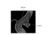
- FIGS. 19 and 20 are diagrams for explaining coiling treatment using a stent.
- the stent placed in the parent vessel is in close contact with the neck portion of the aneurysm after placement.
- the stent for coiling treatment has a very small cross-sectional diameter of the metal constituting the net, it is very difficult to see the degree of adhesion on an X-ray image such as fluoroscopy or radiography.
- doctors and technicians confirm a three-dimensional image reconstructed in a high spatial resolution mode from projection data (hereinafter referred to as an X-ray acquisition image), and the stent is in close contact with the parent vessel and the neck portion of the aneurysm. Make sure that coiling treatment is performed.
- the conventional technique has a problem that it is difficult to clearly observe both the stent and the blood vessel. If the X-ray acquired image is reconstructed with high resolution, even if the stent is clearly drawn up to the strut, the boundary may be difficult to understand as a result of being mixed with irregularities on the blood vessel surface. On the other hand, when the X-ray acquired image is reconstructed with the standard resolution, even if the stent marker is drawn, there is a possibility that the strut is hardly drawn. Further, for example, even if an attempt is made to solve this problem by increasing the number of projection directions, an increase in exposure dose or an increase in the amount of contrast medium injected is caused.
- the medical image processing apparatus includes a first reconstruction unit, a second reconstruction unit, and an image composition unit.
- the first reconstruction unit generates a first reconstruction image by applying a first reconstruction filter based on the X-ray acquired image.
- the second reconstruction unit generates a second reconstruction image based on the X-ray acquired image by applying a second reconstruction filter having a higher high frequency enhancement effect than the first reconstruction filter.
- the image composition unit synthesizes the first reconstructed image and the second reconstructed image.
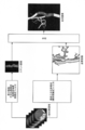
- FIG. 1 is a block diagram showing the configuration of the X-ray diagnostic apparatus according to the first embodiment.
- FIG. 2 is a flowchart showing an overall processing flow by the X-ray diagnostic apparatus according to the first embodiment.
- FIG. 3A is a diagram for explaining density unevenness correction according to the first embodiment.
- FIG. 3B is a diagram for explaining density unevenness correction according to the first embodiment.
- FIG. 4 is a diagram for explaining reconstruction and synthesis processing according to the first embodiment.
- FIG. 5 is a diagram for explaining reconstruction and synthesis processing (Modification 1) according to the first embodiment.
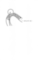
- FIG. 6 is a diagram for explaining the stent marker according to the first embodiment.
- FIG. 7 is a diagram for explaining reconstruction and synthesis processing (Modification 2) according to the first embodiment.
- FIG. 1 is a block diagram showing the configuration of the X-ray diagnostic apparatus according to the first embodiment.
- FIG. 2 is a flowchart showing an overall processing flow by the X-ray diagnostic apparatus according to the first embodiment.
- FIG. 8 is a diagram for explaining reconfiguration and synthesis processing according to the second embodiment.
- FIG. 9 is a diagram for explaining reconfiguration and synthesis processing (Modification 1) according to the second embodiment.
- FIG. 10 is a diagram for explaining reconstruction and synthesis processing (Modification 2) according to the second embodiment.
- FIG. 11 is a flowchart showing the flow of the reconstruction process according to the third embodiment.
- FIG. 12 is a diagram for explaining a reconstruction process according to the third embodiment.
- FIG. 13 is a diagram for explaining a reconstruction area according to the third embodiment.
- FIG. 14 is a diagram for explaining discrete intervals according to the third embodiment.
- FIG. 15 is a diagram for explaining discrete intervals according to the third embodiment.
- FIG. 16 is a diagram for explaining a convolution filter according to the third embodiment.
- FIG. 17 is a diagram for explaining the position of the second reconstruction area according to the third embodiment.
- FIG. 18 is a diagram for explaining the designation of the position of the second reconstruction area according to the third embodiment.
- FIG. 19 is a diagram for explaining coiling treatment using a stent.
- FIG. 20 is a diagram for explaining coiling treatment using a stent.
- FIG. 1 is a block diagram showing the configuration of the X-ray diagnostic apparatus 1 according to the first embodiment.
- the X-ray diagnostic apparatus 1 according to the first embodiment includes an X-ray imaging mechanism 10 and an image processing apparatus 100.
- the X-ray imaging mechanism 10 includes an X-ray tube 11, a detector (FPD (Flat Panel Detector)) 12, a C-type arm 13, and a bed 14.
- the C-shaped arm 13 supports the X-ray tube 11 and the detector 12 and rotates at high speed around the subject P like a propeller by a motor provided on a base (not shown).
- the image processing apparatus 100 includes a control unit 20, an A / D (Analog / Digital) conversion unit 21, a two-dimensional image storage unit 22, a subtraction unit 23, a three-dimensional reconstruction unit 24, and a three-dimensional image storage unit. 25, a three-dimensional image composition unit 26, a three-dimensional image display unit 27, and a monitor 28.
- a / D Analog / Digital
- the control unit 20 controls the entire X-ray diagnostic apparatus 1. Specifically, the control unit 20 controls the collection of the X-ray acquisition image, the reconstruction of the 3D image, the display of the 3D image, and the like.
- the A / D conversion unit 21 is connected to the detector 12, converts the analog signal input from the detector 12 into a digital signal, and stores the converted digital signal in the two-dimensional image storage unit 22 as an X-ray acquired image. .
- the two-dimensional image storage unit 22 stores an X-ray collection image.
- the subtraction unit 23 performs subtraction between the X-ray acquisition image and the density unevenness correction image, and acquires a subtraction image.
- the three-dimensional reconstruction unit 24 reconstructs a three-dimensional image from the subtraction image. As illustrated in FIG. 1, the three-dimensional reconstruction unit 24 includes a first reconstruction unit 24a, a second reconstruction unit 24b, a specifying unit 24c, and an identification unit 24d. Each of these parts will be described in detail later.
- the three-dimensional image storage unit 25 stores a three-dimensional image.
- the three-dimensional image combining unit 26 combines the reconstructed three-dimensional image.
- the three-dimensional image display unit 27 displays the three-dimensional image on the monitor 28 as a volume rendering image or an MPR (Multi Planar Reconstruction) image.
- MPR Multi Planar Reconstruction
- FIG. 2 is a flowchart showing an overall processing flow by the X-ray diagnostic apparatus 1 according to the first embodiment.
- step S1 preparation for photographing is performed (step S1). Specifically, when interventional therapy is initiated, the physician inserts the catheter into the blood vessel, and when the catheter reaches near the intended aneurysm, it covers the neck that is the boundary between the aneurysm and the parent vessel Indwell the stent. The physician performs 3D imaging to see if the stent completely covers the neck, whether the stent is in close contact with the vessel wall, whether the stent is not damaged, and the like.
- the C-arm 13 rotates at high speed around the subject P (for example, 180 degrees or more around the subject P) like a propeller by a motor provided on the base.
- the doctor adjusts any one or a combination of the position of the bed 14, the height of the bed 14, and the position of the C-arm 13 so that the target main blood vessel enters the visual field in all directions. Thereafter, when the doctor confirms whether or not the subject P is dangerous due to the rotation of the C-shaped arm 13, preparation for imaging is completed.
- the doctor sets a contrast medium injector (Injector) in the X-ray diagnostic apparatus 1.
- a contrast medium injector injector
- a contrast medium used for normal angiography is diluted 2 to 3 times. This is because when a high contrast agent concentration is used, the contrast agent component cancels the information of the stent.
- step S2 the injection of the contrast medium is started (step S2), and after a certain time (for example, 1 second to 2 seconds) has passed since the injection of the contrast medium has started, rotation and imaging of the C-arm 13 are started (step S3). ), An X-ray collection image is taken (step S4).
- a certain time for example, 1 second to 2 seconds
- the C-arm 13 rotates at 25 degrees per second, and the X-ray diagnostic apparatus 1 captures about 250 frames of X-ray collected images at intervals of about 0.8 degrees.
- the A / D conversion unit 21 converts the collected X-ray acquired image of 250 frames into a digital signal, and stores it in the two-dimensional image storage unit 22 as an amount corresponding to 250 frames of 1,024 ⁇ 1,024 X-ray acquired images.
- the control unit 20 uses the X-ray collected image stored in the two-dimensional image storage unit 22 and the density unevenness correction image collected in advance.
- the subtraction unit 23 performs subtraction (step S5). Specifically, the subtraction unit 23 subtracts the X-ray collection image from the corresponding density unevenness correction image.
- 3A and 3B are diagrams for explaining density unevenness correction according to the first embodiment.
- the image for correcting density unevenness is an image taken with only air between the X-ray tube 11 and the detector 12. In the calibration procedure, For example, it is collected regularly once every several months.
- the image for correcting density unevenness is collected for each SID (Source Image Distance), FOV (Field Of View), and line quality adjustment filter.
- An image collected by the shooting shown in FIG. 3A is assumed to be “F (x, y)”.
- an image taken with a uniform substance between the X-ray tube 11 and the detector 12 is assumed to be “P (x, y)”.
- the following equation (1) is established.
- the subtraction unit 23 obtains a subtraction image Q ⁇ (x, y) by applying the following equation (2) using the X-ray acquired image and the density unevenness correction image.
- ⁇ represents a shooting angle.
- P ⁇ (x, y) is an X-ray collection image of the subject at an imaging angle ⁇
- F (x, y) is an image for correcting density unevenness
- Q ⁇ (x, y) is an imaging angle ⁇ . It is a subtraction image in.
- the control unit 20 sends the subtraction image Q ⁇ (x, y) to the three-dimensional reconstruction unit 24, and the three-dimensional reconstruction unit 24 performs reconstruction (step S6).
- subtraction image Q ⁇ (x, y) is described as “X-ray projection image”.
- the three-dimensional reconstruction unit 24 and the three-dimensional image synthesis unit 26 perform two types of reconstruction, synthesize two types of reconstruction images obtained by the respective reconstructions, Output a composite image.
- the first reconstruction unit 24a of the three-dimensional reconstruction unit 24 generates a first reconstruction image by applying a first reconstruction filter based on the X-ray acquired image.
- the second reconstruction unit 24b of the three-dimensional reconstruction unit 24 generates a second reconstruction image by applying a second reconstruction filter based on the X-ray acquired image.
- the second reconstruction filter is a reconstruction filter having a high frequency enhancement effect as compared with the first reconstruction filter.
- the three-dimensional image synthesis unit 26 synthesizes the first reconstructed image and the second reconstructed image.
- the processing by the specifying unit 24c and the identification unit 24d is not performed. Therefore, the three-dimensional reconstruction unit 24 may not include these units.
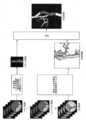
- FIG. 4 is a diagram for explaining reconfiguration and synthesis processing according to the first embodiment.
- the three-dimensional reconstruction unit 24 uses a standard reconstruction filter (hereinafter referred to as “standard reconstruction filter” as appropriate) for the X-ray projection image sent from the subtraction unit 23.
- standard reconstruction filter a standard reconstruction filter having a high effect of high frequency enhancement
- each reconstruction filter is, for example, one of the reconstruction filter of Ramachhandran, the reconstruction filter of Smoothed Shepp & Logan, and the reconstruction filter of Shepp & Logan.
- Two types of reconstruction filters may be used in appropriate combination so that the effect of high-frequency emphasis is relatively high with respect to these reconstruction filters.
- the first reconstruction unit 24 a When the first reconstruction is performed using the standard reconstruction filter, as illustrated in FIG. 4, the first reconstruction unit 24 a generates a reconstruction image (“blood vessel image” illustrated in FIG. 4) in which blood vessels are depicted. obtain. Since this reconstructed image is reconstructed by the standard reconstruction filter, the stent is hardly depicted. However, the overall structure of the blood vessel is depicted in an easy-to-observe manner without excessively emphasizing the irregularities on the blood vessel surface.
- the second reconstruction unit 24 b reconstructs the reconstructed image in which the stent is clearly depicted up to the strut (see FIG. 4).
- a “stent image”) is obtained.
- FIG. 4 shows a stent image in which only the stent portion is extracted, but in actuality, this is an image in which both the stent and the blood vessel are depicted.
- the stent is a metal and has a high CT (Computed Tomography) value. Therefore, the second reconstruction unit 24b adjusts the window width and the window level with respect to the reconstructed image so as to deepen the depiction of the stent and thin the depiction of the blood vessel.
- the window width is, for example, a density value range assigned to the range from the maximum brightness to the minimum brightness
- the window level is, for example, a density value located in the middle of the window width.
- FIG. 4 shows an example in which two types of reconfiguration are performed in parallel
- the present invention is not limited to this.
- the reconstruction using the high frequency enhancement reconstruction filter is performed. It may be a flow for performing reconfiguration.
- the control unit 20 when two types of reconstructed images are stored in the three-dimensional image storage unit 25, the control unit 20 combines the two types of reconstructed images stored in the three-dimensional image storage unit 25 with a three-dimensional image composition. Send to part 26. Then, the three-dimensional image synthesis unit 26 synthesizes two types of reconstructed images. Specifically, the three-dimensional image synthesis unit 26 synthesizes the reconstructed image obtained by the first reconstruction and the reconstructed image obtained by the second reconstruction, and outputs a synthesized image. In this composite image, the stent and the blood vessel are drawn in a superimposed manner.
- the composite image is an image in which the entire structure of the blood vessel can be observed and the stent is clearly depicted as shown in FIG.
- control unit 20 sends the combined three-dimensional image to the three-dimensional image display unit 27, and the three-dimensional image display unit 27 displays the combined three-dimensional image.
- the volume rendering image or MPR image is displayed on the monitor 28.
- both the stent and the blood vessel can be clearly observed. That is, according to the first embodiment, two types of reconstruction are performed on an X-ray acquired image, and by combining these, an entire blood vessel structure can be observed and an image in which a stent is clearly depicted is obtained. Therefore, both the stent and the blood vessel can be clearly observed without particularly increasing the number of projection directions.
- FIG. 5 is a diagram for explaining reconstruction and synthesis processing (Modification 1) according to the first embodiment. The difference between the reconstruction process and the synthesis process described with reference to FIG. 4 will be mainly described.
- the three-dimensional reconstruction unit 24 according to the first modification uses the first reconstruction filter by the standard reconstruction filter. A region of interest is extracted using the reconstructed image of the configuration, and the second reconstruction by the high frequency emphasis reconstruction filter is performed only for the extracted region of interest.
- the three-dimensional reconstruction unit 24 performs processing by the specifying unit 24c and the identifying unit 24d.
- the identifying unit 24c identifies the stent marker by threshold processing for the reconstructed image of the first reconstruction.
- the identification unit 24d identifies a region of interest surrounded by the stent marker in the reconstructed image of the first reconstruction.
- the second reconstruction unit 24b applies the high frequency enhancement reconstruction filter only to the attention region identified by the identification unit 24d in the X-ray acquired image, and generates the reconstruction image only for the attention region.
- FIG. 6 is a diagram for explaining the stent marker according to the first embodiment.
- the specifying unit 24c according to Modification 1 specifies a stent marker by performing image processing on the reconstructed image of the first reconstruction.
- the stent markers are positioned at both ends of the stent (for example, four at each end are provided).
- This stent marker has a high absorption rate and a high CT value only in the stent marker portion.
- the specifying unit 24c can specify a stent marker by performing threshold processing, for example, and the identifying unit 24d further extracts a region surrounded by the stent marker specified by the specifying unit 24c.
- the region i.e. the region of the stent, is identified.
- the metal artificial tooth has a high CT value as well, but its volume is very large compared to the stent marker. Therefore, the artificial tooth can be excluded by measuring the volume.
- the second reconstruction unit 24b performs the second reconstruction using only the high-frequency emphasis reconstruction filter only for the stent region, only the stent portion is extracted as shown in FIG. A stent image in which the stent is clearly depicted is obtained.
- the window width and the window level can be easily adjusted as described above. Further, since the area for the second reconstruction becomes smaller, the time required for the reconstruction is also reduced. Then, the three-dimensional image composition unit 26, as in the first embodiment described with reference to FIG. 4, the reconstructed image obtained by the first reconstruction, the reconstructed image obtained by the second reconstruction, Is synthesized.
- FIG. 7 is a diagram for explaining reconstruction and synthesis processing (Modification 2) according to the first embodiment. The difference from the reconstruction and synthesis processing described with reference to FIG. 5 will be mainly described.
- the region of interest is extracted as post-processing of the second reconstruction by the high frequency enhancement reconstruction filter.
- the second reconstruction unit 24b performs the second reconstruction by the high-frequency enhancement reconstruction filter on the entire X-ray projection image as in the first embodiment described with reference to FIG. To do.
- the specifying unit 24c specifies a stent marker by threshold processing on the first reconstructed image
- the identifying unit 24d identifies a region of interest surrounded by the stent marker in the second reconstructed image.
- the identification unit 24d applies the information of the attention area obtained from the reconstructed image of the first reconstruction, and cuts out the stent area from the reconstructed image of the second reconstruction.
- the three-dimensional image composition unit 26 generates a reconstructed image obtained by the first reconstruction, and a reconstructed image obtained by the second reconstruction, in which only the stent region is cut out. Synthesize. As described above, also in the second modification, the window width and the window level can be easily adjusted.
- the second embodiment is assumed to be implemented by an X-ray diagnostic apparatus 1 similar to the X-ray diagnostic apparatus 1 described in the first embodiment.
- the difference from the first embodiment is that, in the first embodiment, two types of reconstruction are performed on the image after contrast medium injection.
- the contrast medium is contrasted. Images before and after injection are collected, and two types of reconstruction are performed using these subtraction images and images before contrast agent injection.
- a description will be given focusing on differences from the first embodiment.
- FIG. 8 is a diagram for explaining reconfiguration and synthesis processing according to the second embodiment.
- the subtraction unit 23 performs subtraction between an image before contrast agent injection (hereinafter referred to as “mask image” as appropriate) and an image for correcting density unevenness, and in addition to the mask image and contrast agent. Subtraction is performed between the injected image (hereinafter referred to as “contrast image” as appropriate).
- the image obtained by the former subtraction is appropriately referred to as an X-ray projection image
- the image obtained by the latter subtraction is hereinafter appropriately referred to as a DSA (Digital Subtraction Angiography) image.
- the subtraction unit 23 according to the second embodiment sends the X-ray projection image and the DSA image to the three-dimensional reconstruction unit 24.
- the three-dimensional reconstruction unit 24 performs the first reconstruction by the standard reconstruction filter on the DSA image sent from the subtraction unit 23, and performs high-frequency enhancement reconstruction on the X-ray projection image.
- a second reconfiguration is performed with the configuration filter. That is, the first reconstruction unit 24a performs the first reconstruction by applying the standard reconstruction filter to the DSA image, and the second reconstruction unit 24b performs the high-frequency enhancement reconstruction on the X-ray projection image.
- a second reconfiguration is performed by applying a configuration filter.
- the X-ray projection image is before contrast medium injection
- blood vessels are not drawn.
- the reconstructed image of the second reconstruction blood vessels are not depicted, and as a result, only the stent is clearly depicted.
- the adjustment of the window width and the window level as described above becomes easier.
- the DSA image is a subtraction image before and after contrast agent injection, only the blood vessels are depicted.
- the 3D image synthesis unit 26 synthesizes the reconstructed image obtained by the first reconstruction and the reconstructed image obtained by the second reconstruction, as in the first embodiment.
- both the stent and the blood vessel can be observed more clearly. That is, according to the second embodiment, two types of reconstruction are performed for each of the image in which only the stent is depicted and the image in which only the blood vessel is depicted, and these are combined, so one image Thus, unnecessary superimposition such as overlapping of a stent or blood vessel drawn unclearly does not occur, and both the stent and blood vessel can be observed more clearly.
- FIG. 9 is a diagram for explaining reconfiguration and synthesis processing (Modification 1) according to the second embodiment.
- the difference from the reconstruction and composition processing described with reference to FIG. 8 will be mainly described.
- the three-dimensional reconstruction unit 24 according to the first modification is not limited to the DSA image.
- the first reconstruction by the standard reconstruction filter is also performed on the X-ray projection image. That is, as described above, blood vessels are not drawn in the X-ray projection image. Therefore, the specifying unit 24c according to the modified example 1 performs the first reconstruction by the standard reconstruction filter on the X-ray projection image and performs image processing on the reconstructed image, so that the stent marker is detected. Identify.
- the second reconstruction unit 24b performs the second reconstruction using the high-frequency enhanced reconstruction filter only for the stent region. As shown in FIG. 9, only the stent portion is extracted, and a stent image in which the stent is clearly depicted is obtained. Thus, according to the modification 1 of 2nd Embodiment, adjustment of a window width or a window level becomes unnecessary. Further, since the area for the second reconstruction becomes smaller, the time required for the reconstruction is also reduced.
- this attention area may be determined by accepting an operator's designation.
- FIG. 10 is a diagram for explaining reconstruction and synthesis processing (Modification 2) according to the second embodiment. The difference from the reconstruction and synthesis processing described with reference to FIG. 9 will be mainly described.
- the region of interest is extracted as post-processing of the second reconstruction by the high frequency enhancement reconstruction filter.
- the second reconstruction unit 24b performs the second reconstruction by the high-frequency enhancement reconstruction filter on the entire X-ray projection image as in the second embodiment described with reference to FIG. To do.
- the identifying unit 24c performs the first reconstruction by applying a standard reconstruction filter to the X-ray projection image, and identifies the stent marker by threshold processing on the reconstructed image.
- the identifying unit 24d identifies a region of interest surrounded by the stent marker in the reconstructed image of the second reconstruction. That is, the identification unit 24d applies the information of the attention area obtained from the reconstructed image of the first reconstruction, and cuts out the stent area from the reconstructed image of the second reconstruction.
- the three-dimensional image composition unit 26 generates a reconstructed image obtained by the first reconstruction, and a reconstructed image obtained by the second reconstruction, in which only the stent region is cut out. Synthesize. As described above, also in the second modification, the adjustment of the window width and the window level is simplified.
- a reconstruction filter will be described.
- one of the reconstruction filter of Ramachhandran, the reconstruction filter of Smoothed Shepp & Logan, and the reconstruction filter of Shepp & Logan is relative to the other reconstruction filter.
- the two types of reconstruction filters may be used in appropriate combination so that the effect of high frequency enhancement is enhanced.
- the reconstruction filter when the effect of high frequency enhancement is relatively high, the reconstruction filter is called “sharp convolution filter”, and when the effect of high frequency enhancement is relatively low, the reconstruction filter is referred to as “smooth convolution”. This is called “filter”.
- the first reconstruction unit 24a of the three-dimensional reconstruction unit 24 performs a reduction process and a low-pass filter process in advance.
- FIG. 11 is a flowchart showing the flow of the reconstruction process according to the third embodiment.
- the three-dimensional reconstruction unit 24 performs “first-stage reconstruction” and “second-stage reconstruction”.
- the example in which the three-dimensional reconstruction unit 24 performs the “first-stage reconstruction” and the “second-stage reconstruction” in parallel is shown, but the present invention is not limited thereto. is not. For example, even if it is a flow for performing “second stage reconstruction” after performing “first stage reconstruction”, or after performing “second stage reconstruction”, It may be a flow for executing the “configuration”.
- FIG. 12 is a diagram for explaining a reconstruction process according to the third embodiment.
- the three-dimensional reconstruction unit 24 reduces the X-ray projection image (step S101).
- the three-dimensional reconstruction unit 24 uses a 1,024 ⁇ 1,024 X-ray projection image with a reduced pixel size of 4 pixels before reduction.
- the X-ray projection image is reduced so that there are minutes.
- the reduced X-ray projection image is equivalent to 250 frames of 512 ⁇ 512 X-ray projection images.
- the three-dimensional reconstruction unit 24 applies a smooth convolution filter such as Smoothed Shepp & Logan to the reduced 512 ⁇ 512 X-ray projection image 250 frames. (Step S102).
- the three-dimensional reconstruction unit 24 (first reconstruction unit 24a) performs a back projection operation to generate a first three-dimensional image, and the generated first three-dimensional image is stored in the three-dimensional image storage unit 25.
- Store (step S103).
- the three-dimensional reconstruction unit 24 extracts a part from the X-ray projection image (step S201). For example, the three-dimensional reconstruction unit 24 (second reconstruction unit 24b) extracts a 512 ⁇ 1,024 X-ray projection image from a 1,024 ⁇ 1,024 subtraction image, as shown in FIG. As a result, the three-dimensional reconstruction unit 24 (second reconstruction unit 24b) acquires 250 frames of 512 ⁇ 1,024 X-ray projection images.
- the three-dimensional reconstruction unit 24 performs reconstruction processing on the extracted X-ray projection image.
- the reconstruction method here, the case of the filtered back projection method proposed by Feldkamp and the like is shown.
- the three-dimensional reconstruction unit 24 applies a sharp convolution filter such as Shepp & Logan or Ramachandran to the extracted 512 ⁇ 1,024 X-ray projection images for 250 frames (steps). S202).
- the three-dimensional reconstruction unit 24 (second reconstruction unit 24b) performs a back projection operation to generate a second three-dimensional image, and the generated second three-dimensional image is stored in the three-dimensional image storage unit 25.
- Store (step S203).
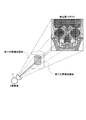
- FIG. 13 is a diagram for explaining a reconstruction area according to the third embodiment.
- FIGS. 14 and 15 are diagrams for explaining the discrete intervals according to the third embodiment.
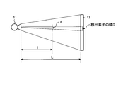
- the second reconstruction area is a quadrangular pyramid composed of an X-ray tube 11 and an area of the center (FOV / 2 ⁇ FOV / 2) of the FOV of the detector 12.
- FOV / 2 ⁇ FOV / 2 the center of the FOV of the detector 12.
- this cylinder has a three-dimensional length “d” at the center of the reconstruction area projected onto the width “D” of one detection element of the detector 12, for example. Is discretized.
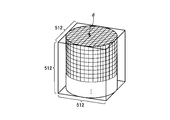
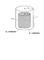
- the three-dimensional reconstruction unit 24 generates 512 ⁇ 512 ⁇ 512 discrete point data, which is three-dimensionally discretized with the length “d”, as the second three-dimensional image. Since the second three-dimensional image is reconstructed from the 512 ⁇ 1,024 X-ray projection image, the three-dimensional reconstruction unit 24 is not only in the cylinder shown in FIG. Thus, data in a 512 ⁇ 512 ⁇ 512 cube can be generated.
- the discrete interval is shown here, this may differ depending on the device or manufacturer, so basically, the discrete interval defined by the device may be used.
- the first reconstruction area is formed by overlapping a pyramid composed of the X-ray tube 11 and the FOV area of the detector 12 in all directions. Defined as a cylinder inscribed in The inside of this cylinder is discretized three-dimensionally with a length “2d”. In this way, the three-dimensional reconstruction unit 24 generates 512 ⁇ 512 ⁇ 512 discrete point data that is three-dimensionally discretized with the length “2d” as the first three-dimensional image.
- FIG. 16 is a diagram for explaining a convolution filter according to the third embodiment.
- the convolution filters generally include a “smooth” convolution filter used in “first stage reconstruction” and a “sharp” convolution filter used in “second stage reconstruction”.
- a “sharp” convolution filter has a property of high-frequency enhancement compared to a “smooth” convolution filter.
- FIG. 16 shows three types of convolution filters.
- the Ramachhandran convolution filter is the most “sharp”
- the Smoothed Shepp & Logan convolution filter is the most “smooth”
- the Shepp & Logan convolution filter is in the middle.
- the X-ray diagnostic apparatus 1 when reconstruction is performed using a “sharp” convolution filter, high-frequency is emphasized, and a clear image is likely to be obtained. That is, the X-ray diagnostic apparatus 1 according to the third embodiment not only performs different processes for “first-stage reconstruction” and “second-stage reconstruction”, but also applies a convolution filter to each. Even without changing, the image of the region of interest can be extracted more clearly, and the image degradation in the peripheral portion can be suppressed.
- the first three-dimensional image and the second three-dimensional image are generated.
- the second three-dimensional image It can be seen that one voxel size is smaller than the one voxel size of the first three-dimensional image and its spatial resolution is high. That is, since the second three-dimensional image is generated from the subtraction image extracted as it is without being reduced, the one voxel size has high spatial resolution when the X-ray acquisition image is acquired. Keep it as it is. On the other hand, since the first three-dimensional image is generated from the reduced subtraction image, the one voxel size is lower than the spatial resolution when the X-ray acquired image is acquired.
- the 3D image synthesis unit 26 according to the third embodiment synthesizes 3D images, as in the first embodiment and the second embodiment.
- the three-dimensional image composition unit 26 synthesizes the first three-dimensional image and the second three-dimensional image as shown in FIG.
- the three-dimensional image composition unit 26 according to the third embodiment preferentially adopts the second three-dimensional image for the region where the first three-dimensional image and the second three-dimensional image overlap. .
- the second reconstruction area is the center of the first reconstruction area.
- the present invention is not limited to this, and the second reconstruction area may be shifted from the center.
- the phenomenon of image quality deterioration may occur in the peripheral portion of the first reconstruction area, it is not desirable that the second reconstruction area is far from the center.
- FIG. 17 is a diagram for explaining the position of the second reconstruction area according to the third embodiment.
- the second reconstruction area is in an area included in a cylinder having a radius “R” and a height “h” of 2/3 of the first reconstruction area. desirable.
- FIG. 18 is a diagram for explaining the designation of the position of the second reconstruction area according to the first embodiment.
- the center circle is a top view of the cylinder of the first reconstruction area or the second reconstruction area.
- the three-dimensional reconstruction unit 24 may extract the X-ray projection image so that the aneurysm determined in the three-dimensional space is centered in the second reconstruction stage.
- the third embodiment it is possible to simultaneously render a wide area (for example, all areas in the field of view) and a clear depiction of the attention area. For example, it is possible to satisfy the clinical needs of observing the region of interest of the stent in detail while grasping the entire structure of the blood vessel and further reducing the exposure to the patient as much as possible.
- the three-dimensional reconstruction unit 24 performs convolution filter processing when generating the first three-dimensional image and the second three-dimensional image.
- the convolution filter process performed for generating the second three-dimensional image is higher-frequency emphasis than the convolution filter process performed for generating the first three-dimensional image.
- the image of the attention area can be drawn more clearly.
- the three-dimensional image combining unit 26 simply combines the first three-dimensional image and the second three-dimensional image, but the present invention is not limited to this.
- the pixel level may be slightly different between the first three-dimensional image and the second three-dimensional image due to several factors such as various correction effects. For this reason, the three-dimensional image composition unit 26 compares the pixel level of the portion corresponding to the second reconstruction area in the first three-dimensional image with the pixel level of the second three-dimensional image, and performs correction. It is desirable to do.
- the three-dimensional image composition unit 26 calculates the average pixel level AV2 of the second three-dimensional image and the average pixel level AV1 of the portion corresponding to the second reconstruction area in the first three-dimensional image, The difference (AV1-AV2) is obtained, and the obtained (AV1-AV2) is added to the pixels of the second three-dimensional image. This is a global correction.
- the 3D image composition unit 26 may further perform local correction after performing global correction.
- the three-dimensional image composition unit 26 calculates the average pixel level in a small region (for example, 32 ⁇ 32) in the second three-dimensional image, and the second three-dimensional image in the small region in the first three-dimensional image. Is compared with the average pixel level in the small area corresponding to the small area, and correction is performed so that a large difference does not occur between the two pixel levels. By performing such correction, the pixel level is adjusted between the first three-dimensional image and the second three-dimensional image, so that the boundary between both images becomes smoother in the combined three-dimensional image. It is drawn. Note that these corrections described in the first modification can be similarly applied to the first embodiment and the second embodiment.
- the three-dimensional reconstruction unit 24 (first reconstruction unit 24a) performs a reduction process as a pre-process for the first-stage reconstruction.
- the low-pass filter process may be performed on the X-ray acquired image without performing the reduction process, and the reconstruction may be performed on the filtered image subjected to the low-pass filter process.
- the shape of the low-pass filter is a value of 1/4 in a 2 ⁇ 2 region, the result is exactly the same as the reduction process.
- the three-dimensional reconstruction unit 24 (first reconstruction unit 24a) synthesizes a low-pass filter and a convolution filter as a first-stage reconstruction, and directly applies this synthesis filter to the X-ray acquired image. It may be used to perform the reconstruction process. In this modification, the discrete interval of the first stage reconstruction does not necessarily have to be “2d” in length.
- the three-dimensional reconstruction unit 24 (first reconstruction unit 24a) uses a low-pass filter that is slightly sharper than the low-pass filter equivalent to the reduction process, and reconstructs at a discrete interval of length “1.5d”, for example. Also good.
- the three-dimensional reconstruction unit 24 (second reconstruction unit 24b) performs reconstruction by extracting only the central 512 ⁇ 1,024 portion.
- the second-stage reconstruction is performed with emphasis on spatial resolution, not density resolution. Therefore, the three-dimensional reconstruction unit 24 (second reconstruction unit 24b) may extract and process the central 512 ⁇ 512 portion instead of extracting the 512 ⁇ 1,024 portion. In this case, the density resolution of the reconstructed image is somewhat lowered, but there is an advantage that the filtering process can be completed in a short time.
- the second three-dimensional image generated by the three-dimensional reconstruction unit 24 is not a 512 ⁇ 1,024 X-ray projection image, but a 512 ⁇ 512 X-ray projection. Reconstructed from images. Therefore, the three-dimensional reconstruction unit 24 (second reconstruction unit 24b) can generate data only in the cylinder shown in FIG. 15, and is data outside the cylinder, which is a 512 ⁇ 512 ⁇ 512 cube. Cannot be generated (a predetermined value is appropriately filled in).
- the medical image processing apparatus may be incorporated in an X-ray CT apparatus. Further, for example, the medical image processing apparatus according to the embodiment may be realized as a single medical image processing apparatus. In this case, the medical image processing apparatus acquires the X-ray acquired image collected by the medical image diagnostic apparatus, and generates a three-dimensional image based on the acquired X-ray acquired image.
- the medical image processing apparatus may be connected to a medical image diagnostic apparatus such as an X-ray diagnostic apparatus or an X-ray CT apparatus via a network and obtain an X-ray acquired image by receiving from the medical image diagnostic apparatus. .
- the medical image processing apparatus When implemented as a single medical image processing apparatus, the medical image processing apparatus includes the three-dimensional reconstruction unit 24 and the three-dimensional image composition unit 26 described in the above-described embodiment.
- the A / D conversion unit 21 and the subtraction unit 23 whether the data received from the medical image diagnostic apparatus is an analog signal, an X-ray acquired image converted into a digital signal, or subtraction has been performed. What is necessary is just to be suitably provided according to the format of data, such as whether it is an X-ray projection image.
- the 2D image storage unit 22 and the 3D image storage unit 25 may be appropriately provided depending on the operation mode, such as whether a storage device is built in or externally attached.
- the monitor 28 may be appropriately provided depending on the operation mode, such as whether a display device is built in or externally attached.
- first-stage reconstruction is performed based on pre-processed data
- second-stage reconstruction is performed based on data that has not been pre-processed. ing. Since the pre-processing is equivalent to applying a “smooth” convolution filter, the convolution filter applied to each of “first-stage reconstruction” and “second-stage reconstruction” For example, the same convolution filter may be used.
- both the stent and the blood vessel can be clearly observed.
Landscapes
- Health & Medical Sciences (AREA)
- Life Sciences & Earth Sciences (AREA)
- Engineering & Computer Science (AREA)
- Medical Informatics (AREA)
- Surgery (AREA)
- Veterinary Medicine (AREA)
- Public Health (AREA)
- Nuclear Medicine, Radiotherapy & Molecular Imaging (AREA)
- General Health & Medical Sciences (AREA)
- Animal Behavior & Ethology (AREA)
- Biomedical Technology (AREA)
- Heart & Thoracic Surgery (AREA)
- Molecular Biology (AREA)
- Physics & Mathematics (AREA)
- Optics & Photonics (AREA)
- Radiology & Medical Imaging (AREA)
- Pathology (AREA)
- High Energy & Nuclear Physics (AREA)
- Biophysics (AREA)
- Vascular Medicine (AREA)
- Computer Vision & Pattern Recognition (AREA)
- Theoretical Computer Science (AREA)
- Human Computer Interaction (AREA)
- Dentistry (AREA)
- Oral & Maxillofacial Surgery (AREA)
- Pulmonology (AREA)
- Neurosurgery (AREA)
- Reproductive Health (AREA)
- General Physics & Mathematics (AREA)
- Apparatus For Radiation Diagnosis (AREA)
- Prostheses (AREA)
- Media Introduction/Drainage Providing Device (AREA)
- Image Processing (AREA)
Abstract
La présente invention concerne un dispositif de traitement d'image médicale (1) selon un mode de réalisation, qui comprend les éléments suivants : une première unité de reconfiguration (24a) ; une seconde unité de reconfiguration (24b) ; et une unité de composition d'image (26). La première unité de reconfiguration (24a) produit une première image reconfigurée sur la base d'une image de collecte de rayons X par l'application d'un premier filtre de reconfiguration. La seconde unité de reconfiguration (24b) produit une seconde image reconfigurée sur la base de l'image de collecte de rayons X par l'application d'un second filtre de reconfiguration, avec un effet d'amélioration d'une fréquence supérieure au premier filtre de reconfiguration. L'unité de composition d'image (26) compose la première image reconfigurée et la seconde image reconfigurée.
Priority Applications (2)
| Application Number | Priority Date | Filing Date | Title |
|---|---|---|---|
| CN201180003798.XA CN102573643B (zh) | 2010-10-08 | 2011-10-07 | 医用图像处理装置 |
| US13/858,005 US9466131B2 (en) | 2010-10-08 | 2013-04-06 | Medical image processing device |
Applications Claiming Priority (2)
| Application Number | Priority Date | Filing Date | Title |
|---|---|---|---|
| JP2010-228844 | 2010-10-08 | ||
| JP2010228844 | 2010-10-08 |
Related Child Applications (1)
| Application Number | Title | Priority Date | Filing Date |
|---|---|---|---|
| US13/858,005 Continuation US9466131B2 (en) | 2010-10-08 | 2013-04-06 | Medical image processing device |
Publications (1)
| Publication Number | Publication Date |
|---|---|
| WO2012046844A1 true WO2012046844A1 (fr) | 2012-04-12 |
Family
ID=45927836
Family Applications (1)
| Application Number | Title | Priority Date | Filing Date |
|---|---|---|---|
| PCT/JP2011/073232 WO2012046844A1 (fr) | 2010-10-08 | 2011-10-07 | Dispositif de traitement d'image médicale |
Country Status (4)
| Country | Link |
|---|---|
| US (1) | US9466131B2 (fr) |
| JP (1) | JP5836047B2 (fr) |
| CN (1) | CN102573643B (fr) |
| WO (1) | WO2012046844A1 (fr) |
Cited By (4)
| Publication number | Priority date | Publication date | Assignee | Title |
|---|---|---|---|---|
| US20150327825A1 (en) * | 2014-05-19 | 2015-11-19 | Kabushiki Kaisha Toshiba | X-ray computed tomography apparatus and medical image display apparatus |
| JP2017055973A (ja) * | 2015-09-16 | 2017-03-23 | 富士フイルム株式会社 | 断層画像生成装置、方法およびプログラム |
| JP2020092768A (ja) * | 2018-12-11 | 2020-06-18 | 株式会社日立製作所 | X線トモシンセシス装置、および、画像生成装置 |
| CN112560778A (zh) * | 2020-12-25 | 2021-03-26 | 万里云医疗信息科技(北京)有限公司 | Dr图像身体部位识别方法、装置、设备及可读存储介质 |
Families Citing this family (12)
| Publication number | Priority date | Publication date | Assignee | Title |
|---|---|---|---|---|
| US8768029B2 (en) * | 2010-10-20 | 2014-07-01 | Medtronic Navigation, Inc. | Selected image acquisition technique to optimize patient model construction |
| WO2013111813A1 (fr) * | 2012-01-27 | 2013-08-01 | 株式会社 東芝 | Dispositif médical de traitement d'image |
| DE102012204019B4 (de) * | 2012-03-14 | 2018-02-08 | Siemens Healthcare Gmbh | Verfahren zur Reduzierung von Bewegungsartefakten |
| JP6571313B2 (ja) | 2013-05-28 | 2019-09-04 | キヤノンメディカルシステムズ株式会社 | 医用画像診断装置及び制御方法 |
| KR20150034061A (ko) * | 2013-09-25 | 2015-04-02 | 삼성전자주식회사 | 복수의 클라이언트들에 의한 촬영 환경 설정 방법 및 장치 |
| JP2015084968A (ja) * | 2013-10-31 | 2015-05-07 | 株式会社東芝 | 医用画像処理装置及び医用画像診断装置 |
| EP3175790B1 (fr) * | 2013-11-04 | 2021-09-08 | Ecential Robotics | Procédé de reconstruction d'une image 3d à partir d'images radiologiques |
| US9311570B2 (en) * | 2013-12-06 | 2016-04-12 | Kabushiki Kaisha Toshiba | Method of, and apparatus for, segmentation of structures in medical images |
| JP6537786B2 (ja) * | 2014-06-16 | 2019-07-03 | キヤノンメディカルシステムズ株式会社 | 医用画像処理装置、医用画像処理方法およびx線ct装置 |
| DE102015208905A1 (de) | 2015-05-13 | 2016-11-17 | Siemens Healthcare Gmbh | Verfahren zum Erzeugen eines Bildes |
| DE102018222595A1 (de) | 2018-12-20 | 2020-06-25 | Siemens Healthcare Gmbh | Verfahren zur Bildbearbeitung eines Bilddatensatzes eines Patienten, medizinische Bildgebungseinrichtung, Computerprogramm und elektronisch lesbarer Datenträger |
| JP7450467B2 (ja) | 2020-06-22 | 2024-03-15 | キヤノンメディカルシステムズ株式会社 | 医用画像処理装置、x線診断装置、および医用画像処理プログラム |
Citations (11)
| Publication number | Priority date | Publication date | Assignee | Title |
|---|---|---|---|---|
| JPH03182233A (ja) * | 1989-12-12 | 1991-08-08 | Toshiba Corp | X線画像表示装置 |
| JPH0944645A (ja) * | 1995-07-27 | 1997-02-14 | Fuji Photo Film Co Ltd | 画像処理方法および装置 |
| JP2001283215A (ja) * | 2000-01-24 | 2001-10-12 | Hitachi Medical Corp | 画像処理装置 |
| JP2005005846A (ja) * | 2003-06-10 | 2005-01-06 | Canon Inc | 画像処理装置 |
| JP2005512372A (ja) * | 2001-12-07 | 2005-04-28 | コーニンクレッカ フィリップス エレクトロニクス エヌ ヴィ | ノイズの多い画像中で構造を空間的に強調する医用ビューイングシステム及び方法 |
| JP2005296332A (ja) * | 2004-04-12 | 2005-10-27 | Toshiba Corp | X線診断装置、画像生成装置及び画像生成方法 |
| JP2005349079A (ja) * | 2004-06-14 | 2005-12-22 | Ge Medical Systems Global Technology Co Llc | 放射線撮影装置および画像生成装置 |
| JP2007229254A (ja) * | 2006-03-01 | 2007-09-13 | Toshiba Corp | X線撮像装置及びその方法 |
| JP2007534420A (ja) * | 2004-04-29 | 2007-11-29 | コーニンクレッカ フィリップス エレクトロニクス エヌ ヴィ | Ptca血管造影図の制御に対するビューイング装置 |
| JP2009532162A (ja) * | 2006-04-03 | 2009-09-10 | コーニンクレッカ フィリップス エレクトロニクス エヌ ヴィ | 患者に挿入されている対象物を取り巻く組織の判定 |
| JP2010131371A (ja) * | 2008-10-27 | 2010-06-17 | Toshiba Corp | X線診断装置および画像処理装置 |
Family Cites Families (17)
| Publication number | Priority date | Publication date | Assignee | Title |
|---|---|---|---|---|
| JPH08140964A (ja) * | 1994-11-22 | 1996-06-04 | Hitachi Medical Corp | X線ct装置 |
| FR2813973B1 (fr) * | 2000-09-08 | 2003-06-20 | Ge Med Sys Global Tech Co Llc | Procede et dispositif de generation d'images tridimensionnelles et appareil de radiologie associe |
| US6775405B1 (en) * | 2000-09-29 | 2004-08-10 | Koninklijke Philips Electronics, N.V. | Image registration system and method using cross-entropy optimization |
| US6580937B2 (en) * | 2000-12-30 | 2003-06-17 | Ge Medical Systems Global Technology Co., Llc | Method for optimal imaging of the peripheral vasculature emphasizing distal arterial visualization in a multi-station examination |
| US20040101088A1 (en) * | 2002-11-27 | 2004-05-27 | Sabol John Michael | Methods and apparatus for discriminating multiple contrast agents |
| JP4348989B2 (ja) * | 2003-04-15 | 2009-10-21 | 株式会社島津製作所 | 断層再構成装置およびそれを用いた断層撮影装置 |
| US7432924B2 (en) | 2003-08-28 | 2008-10-07 | Kabushiki Kaisha Toshiba | 3D digital subtraction angiography image processing apparatus |
| JP2006058655A (ja) | 2004-08-20 | 2006-03-02 | Fuji Photo Film Co Ltd | 放射線画像取得方法および装置ならびにプログラム |
| US7839403B2 (en) * | 2005-12-19 | 2010-11-23 | Siemens Aktiengesellschaft | Simultaneous generation of different data sets from a single acquisition run and dual rendering of images |
| JP4745080B2 (ja) * | 2006-02-20 | 2011-08-10 | 猛 中浦 | X線診断装置、画像処理装置及びプログラム |
| US8111895B2 (en) * | 2006-12-06 | 2012-02-07 | Siemens Medical Solutions Usa, Inc. | Locally adaptive image enhancement for digital subtraction X-ray imaging |
| JP5105981B2 (ja) | 2007-07-18 | 2012-12-26 | 株式会社東芝 | 医用画像処理表示装置、およびその処理プログラム |
| JP5517142B2 (ja) * | 2007-10-03 | 2014-06-11 | ジーイー・メディカル・システムズ・グローバル・テクノロジー・カンパニー・エルエルシー | X線ct装置および画像再構成方法 |
| JP5053982B2 (ja) * | 2008-12-05 | 2012-10-24 | 株式会社東芝 | X線診断装置および画像処理装置 |
| US8457374B2 (en) * | 2009-06-22 | 2013-06-04 | Siemens Medical Solutions Usa, Inc. | System for detecting catheterization devices |
| US8643642B2 (en) * | 2009-08-17 | 2014-02-04 | Mistretta Medical, Llc | System and method of time-resolved, three-dimensional angiography |
| US20110081057A1 (en) * | 2009-10-06 | 2011-04-07 | Eigen, Llc | Apparatus for stenosis estimation |
-
2011
- 2011-10-07 CN CN201180003798.XA patent/CN102573643B/zh active Active
- 2011-10-07 JP JP2011222903A patent/JP5836047B2/ja active Active
- 2011-10-07 WO PCT/JP2011/073232 patent/WO2012046844A1/fr active Application Filing
-
2013
- 2013-04-06 US US13/858,005 patent/US9466131B2/en active Active
Patent Citations (11)
| Publication number | Priority date | Publication date | Assignee | Title |
|---|---|---|---|---|
| JPH03182233A (ja) * | 1989-12-12 | 1991-08-08 | Toshiba Corp | X線画像表示装置 |
| JPH0944645A (ja) * | 1995-07-27 | 1997-02-14 | Fuji Photo Film Co Ltd | 画像処理方法および装置 |
| JP2001283215A (ja) * | 2000-01-24 | 2001-10-12 | Hitachi Medical Corp | 画像処理装置 |
| JP2005512372A (ja) * | 2001-12-07 | 2005-04-28 | コーニンクレッカ フィリップス エレクトロニクス エヌ ヴィ | ノイズの多い画像中で構造を空間的に強調する医用ビューイングシステム及び方法 |
| JP2005005846A (ja) * | 2003-06-10 | 2005-01-06 | Canon Inc | 画像処理装置 |
| JP2005296332A (ja) * | 2004-04-12 | 2005-10-27 | Toshiba Corp | X線診断装置、画像生成装置及び画像生成方法 |
| JP2007534420A (ja) * | 2004-04-29 | 2007-11-29 | コーニンクレッカ フィリップス エレクトロニクス エヌ ヴィ | Ptca血管造影図の制御に対するビューイング装置 |
| JP2005349079A (ja) * | 2004-06-14 | 2005-12-22 | Ge Medical Systems Global Technology Co Llc | 放射線撮影装置および画像生成装置 |
| JP2007229254A (ja) * | 2006-03-01 | 2007-09-13 | Toshiba Corp | X線撮像装置及びその方法 |
| JP2009532162A (ja) * | 2006-04-03 | 2009-09-10 | コーニンクレッカ フィリップス エレクトロニクス エヌ ヴィ | 患者に挿入されている対象物を取り巻く組織の判定 |
| JP2010131371A (ja) * | 2008-10-27 | 2010-06-17 | Toshiba Corp | X線診断装置および画像処理装置 |
Cited By (7)
| Publication number | Priority date | Publication date | Assignee | Title |
|---|---|---|---|---|
| US20150327825A1 (en) * | 2014-05-19 | 2015-11-19 | Kabushiki Kaisha Toshiba | X-ray computed tomography apparatus and medical image display apparatus |
| US10238356B2 (en) * | 2014-05-19 | 2019-03-26 | Toshiba Medical Systems Corporation | X-ray computed tomography apparatus and medical image display apparatus |
| JP2017055973A (ja) * | 2015-09-16 | 2017-03-23 | 富士フイルム株式会社 | 断層画像生成装置、方法およびプログラム |
| JP2020092768A (ja) * | 2018-12-11 | 2020-06-18 | 株式会社日立製作所 | X線トモシンセシス装置、および、画像生成装置 |
| JP7177678B2 (ja) | 2018-12-11 | 2022-11-24 | 富士フイルムヘルスケア株式会社 | X線トモシンセシス装置、および、画像生成装置 |
| CN112560778A (zh) * | 2020-12-25 | 2021-03-26 | 万里云医疗信息科技(北京)有限公司 | Dr图像身体部位识别方法、装置、设备及可读存储介质 |
| CN112560778B (zh) * | 2020-12-25 | 2022-05-27 | 万里云医疗信息科技(北京)有限公司 | Dr图像身体部位识别方法、装置、设备及可读存储介质 |
Also Published As
| Publication number | Publication date |
|---|---|
| JP2012096023A (ja) | 2012-05-24 |
| US9466131B2 (en) | 2016-10-11 |
| CN102573643A (zh) | 2012-07-11 |
| JP5836047B2 (ja) | 2015-12-24 |
| CN102573643B (zh) | 2016-04-27 |
| US20130223719A1 (en) | 2013-08-29 |
Similar Documents
| Publication | Publication Date | Title |
|---|---|---|
| JP5836047B2 (ja) | 医用画像処理装置 | |
| RU2471239C2 (ru) | Визуализация трехмерных изображений в комбинации с двумерными проекционными изображениями | |
| JP4859446B2 (ja) | 回転血管撮影のための血管撮影x線診断装置 | |
| JP4854137B2 (ja) | 医用画像診断装置 | |
| Spin-Neto et al. | Cone beam CT image artefacts related to head motion simulated by a robot skull: visual characteristics and impact on image quality | |
| EP1638051B1 (fr) | Procédé et système pour la reconstruction progressive d'images tri-dimensionelles en multi-résolution, en tenant compte d'une région d'intérêt | |
| US8111895B2 (en) | Locally adaptive image enhancement for digital subtraction X-ray imaging | |
| KR101576703B1 (ko) | 화상 처리 장치, 화상 처리 방법 및 컴퓨터 판독 가능 저장 매체 | |
| JP5361439B2 (ja) | 医用画像処理装置及び医用画像処理方法 | |
| EP3326533B1 (fr) | Dispositif tomographique et procédé de traitement d'image tomographique associé | |
| US6366635B1 (en) | Method and apparatus for three-dimensional image-rendering of a spatial and tissue-based configuration through separating high contrast and injected contrast agents in multi-angular x-ray absorption measurement | |
| US9953440B2 (en) | Method for tomographic reconstruction | |
| JP5487172B2 (ja) | 医用画像診断装置及び医用画像処理装置 | |
| KR20160120963A (ko) | 단층 촬영 장치 및 그에 따른 단층 영상 복원 방법 | |
| KR20160065674A (ko) | 의료 영상 장치 및 의료 영상 처리 방법 | |
| US11599977B2 (en) | Image-processing of image datasets of patients | |
| US20060251313A1 (en) | Method of producing a cross-sectional image | |
| US11786193B2 (en) | Metal artifacts reduction in cone beam reconstruction | |
| US11123025B2 (en) | Iso-centering in C-arm computer tomography | |
| JP5854658B2 (ja) | X線ct装置 | |
| Schafer et al. | Intraoperative imaging for patient safety and QA: detection of intracranial hemorrhage using C-arm cone-beam CT | |
| KR20190140345A (ko) | 단층 영상의 생성 방법 및 그에 따른 엑스선 영상 장치 | |
| Schafer et al. | Toward region of interest computer tomography | |
| CN113935936A (zh) | 一种断层融合图像重建方法、装置 | |
| EP3420905A1 (fr) | Amélioration du contraste d'image d'une image à rayons x |
Legal Events
| Date | Code | Title | Description |
|---|---|---|---|
| WWE | Wipo information: entry into national phase |
Ref document number: 201180003798.X Country of ref document: CN |
|
| 121 | Ep: the epo has been informed by wipo that ep was designated in this application |
Ref document number: 11830775 Country of ref document: EP Kind code of ref document: A1 |
|
| NENP | Non-entry into the national phase |
Ref country code: DE |
|
| 122 | Ep: pct application non-entry in european phase |
Ref document number: 11830775 Country of ref document: EP Kind code of ref document: A1 |