WO2012043492A1 - アルミニウム合金製内面溝付き伝熱管 - Google Patents
アルミニウム合金製内面溝付き伝熱管 Download PDFInfo
- Publication number
- WO2012043492A1 WO2012043492A1 PCT/JP2011/071915 JP2011071915W WO2012043492A1 WO 2012043492 A1 WO2012043492 A1 WO 2012043492A1 JP 2011071915 W JP2011071915 W JP 2011071915W WO 2012043492 A1 WO2012043492 A1 WO 2012043492A1
- Authority
- WO
- WIPO (PCT)
- Prior art keywords
- heat transfer
- tube
- transfer tube
- fin
- less
- Prior art date
- Legal status (The legal status is an assumption and is not a legal conclusion. Google has not performed a legal analysis and makes no representation as to the accuracy of the status listed.)
- Ceased
Links
Images


Classifications
-
- F—MECHANICAL ENGINEERING; LIGHTING; HEATING; WEAPONS; BLASTING
- F28—HEAT EXCHANGE IN GENERAL
- F28F—DETAILS OF HEAT-EXCHANGE AND HEAT-TRANSFER APPARATUS, OF GENERAL APPLICATION
- F28F1/00—Tubular elements; Assemblies of tubular elements
- F28F1/10—Tubular elements and assemblies thereof with means for increasing heat-transfer area, e.g. with fins, with projections, with recesses
- F28F1/12—Tubular elements and assemblies thereof with means for increasing heat-transfer area, e.g. with fins, with projections, with recesses the means being only outside the tubular element
- F28F1/24—Tubular elements and assemblies thereof with means for increasing heat-transfer area, e.g. with fins, with projections, with recesses the means being only outside the tubular element and extending transversely
- F28F1/32—Tubular elements and assemblies thereof with means for increasing heat-transfer area, e.g. with fins, with projections, with recesses the means being only outside the tubular element and extending transversely the means having portions engaging further tubular elements
- F28F1/325—Fins with openings
-
- F—MECHANICAL ENGINEERING; LIGHTING; HEATING; WEAPONS; BLASTING
- F28—HEAT EXCHANGE IN GENERAL
- F28F—DETAILS OF HEAT-EXCHANGE AND HEAT-TRANSFER APPARATUS, OF GENERAL APPLICATION
- F28F1/00—Tubular elements; Assemblies of tubular elements
- F28F1/10—Tubular elements and assemblies thereof with means for increasing heat-transfer area, e.g. with fins, with projections, with recesses
- F28F1/40—Tubular elements and assemblies thereof with means for increasing heat-transfer area, e.g. with fins, with projections, with recesses the means being only inside the tubular element
-
- F—MECHANICAL ENGINEERING; LIGHTING; HEATING; WEAPONS; BLASTING
- F25—REFRIGERATION OR COOLING; COMBINED HEATING AND REFRIGERATION SYSTEMS; HEAT PUMP SYSTEMS; MANUFACTURE OR STORAGE OF ICE; LIQUEFACTION SOLIDIFICATION OF GASES
- F25B—REFRIGERATION MACHINES, PLANTS OR SYSTEMS; COMBINED HEATING AND REFRIGERATION SYSTEMS; HEAT PUMP SYSTEMS
- F25B39/00—Evaporators; Condensers
-
- F—MECHANICAL ENGINEERING; LIGHTING; HEATING; WEAPONS; BLASTING
- F28—HEAT EXCHANGE IN GENERAL
- F28F—DETAILS OF HEAT-EXCHANGE AND HEAT-TRANSFER APPARATUS, OF GENERAL APPLICATION
- F28F1/00—Tubular elements; Assemblies of tubular elements
- F28F1/08—Tubular elements crimped or corrugated in longitudinal section
-
- F—MECHANICAL ENGINEERING; LIGHTING; HEATING; WEAPONS; BLASTING
- F28—HEAT EXCHANGE IN GENERAL
- F28F—DETAILS OF HEAT-EXCHANGE AND HEAT-TRANSFER APPARATUS, OF GENERAL APPLICATION
- F28F19/00—Preventing the formation of deposits or corrosion, e.g. by using filters or scrapers
- F28F19/02—Preventing the formation of deposits or corrosion, e.g. by using filters or scrapers by using coatings, e.g. vitreous or enamel coatings
- F28F19/06—Preventing the formation of deposits or corrosion, e.g. by using filters or scrapers by using coatings, e.g. vitreous or enamel coatings of metal
-
- F—MECHANICAL ENGINEERING; LIGHTING; HEATING; WEAPONS; BLASTING
- F28—HEAT EXCHANGE IN GENERAL
- F28F—DETAILS OF HEAT-EXCHANGE AND HEAT-TRANSFER APPARATUS, OF GENERAL APPLICATION
- F28F21/00—Constructions of heat-exchange apparatus characterised by the selection of particular materials
- F28F21/08—Constructions of heat-exchange apparatus characterised by the selection of particular materials of metal
-
- F—MECHANICAL ENGINEERING; LIGHTING; HEATING; WEAPONS; BLASTING
- F28—HEAT EXCHANGE IN GENERAL
- F28F—DETAILS OF HEAT-EXCHANGE AND HEAT-TRANSFER APPARATUS, OF GENERAL APPLICATION
- F28F21/00—Constructions of heat-exchange apparatus characterised by the selection of particular materials
- F28F21/08—Constructions of heat-exchange apparatus characterised by the selection of particular materials of metal
- F28F21/081—Heat exchange elements made from metals or metal alloys
- F28F21/084—Heat exchange elements made from metals or metal alloys from aluminium or aluminium alloys
Definitions
- the present invention relates to an aluminum inner surface grooved heat transfer tube used as a heat transfer tube of a cross fin type heat exchanger used in a domestic air conditioner, a commercial air conditioner, a heat pump type hot water heater and the like. .
- a general cross fin type (also known as fin and tube type) heat exchanger inserts a heat transfer tube into an insertion hole opened in an aluminum heat radiating fin and then has a larger inside diameter than the inside of the heat transfer tube.
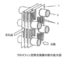
- a mandrel for tube expansion having an outer diameter is pushed in to expand the diameter of the heat transfer tube, and the outer peripheral surface of the heat transfer tube and the insertion hole of the aluminum radiation fin are brought into close contact (tube expansion processing: FIG. 2). Thereafter, the heat transfer tube integrated with the aluminum radiation fin is bent into a hairpin shape, and a heat transfer tube (U-shaped tube) bent in a separate U shape is joined by torch brazing to complete (Non-patent Document 1).
- the heat transfer tube used in the cross fin type heat exchanger is one that causes HFC or the like to flow through the tube as a refrigerant to exchange heat, and a copper heat transfer tube having a trapezoidal or triangular protrusion fin on the inner surface of the tube (Hereinafter referred to as an internally grooved tube) is used to improve the efficiency and energy saving of the heat exchanger.
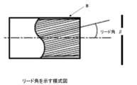
- the depth and bottom thickness of the groove between the projecting fins shown in FIG. Thiickness of the base of the projecting fin), the shape of the fin (vertical angle, etc.), or various transmissions that define the lead angle of the projecting fin shown in FIG.
- a heat pipe has been proposed (for example, Patent Document 1). It is said that the heat transfer performance of the internally grooved tube is superior because the surface area inside the tube is increased compared to the smooth tube, and a uniform refrigerant liquid film is formed in the tube by this groove (non- Patent Document 2).
- the projecting fins arranged in a spiral manner are generally formed on the inner surface of the inner grooved tube by rolling a raw tube (smooth tube).
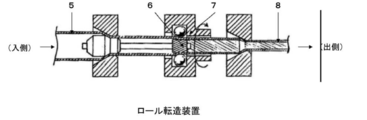
- a rolling method a roll rolling method (see Fig. 3) in which a grooved plug that freely rotates into the pipe is inserted, a roll that freely rotates from the outside of the pipe is pressed, and the pipe is pulled out while rotating planetary (see Fig. 3), or instead of a roll
- a ball rolling method using a ball pressing mechanism is known (Non-patent Document 1, Patent Document 2).
- copper-based materials such as copper and copper alloys have been mainly used for internally grooved pipes, but aluminum-based materials such as aluminum and aluminum alloys (hereinafter referred to as “reducing costs”) , And aluminum alloys) are being studied.
- the heat transfer tube has a two-layer structure, the inner layer of the tube is made of an Al—Mn alloy, and the outer surface layer is coated with an Al—Zn alloy as a sacrificial anticorrosion layer. Grooved tubes have been proposed.
- Patent Document 4 an Al—Mn alloy such as A3003 is used for an inner layer of a heat transfer tube, and an outer surface layer is a sacrificial anticorrosive layer clad with an Al—Zn alloy such as A7072 and the inner grooved tube. Heat exchangers using internally grooved tubes have been proposed.
- Patent Document 5 proposes to form an oxide film having a thickness of 5 ⁇ m or more on the inner surface of the aluminum pipe.
- the inner surface of the aluminum in which the inner layer on which the protruding fins are formed is made of an aluminum alloy layer having a high mechanical strength and the outer layer of the aluminum alloy layer is clad with an aluminum layer having a low mechanical strength.
- Grooved tubes have been proposed.
- an inner layer uses an A3003 aluminum alloy and an outer layer uses A1050 (pure aluminum).
- the outer peripheral tube bottom portion made of A1050 is preferentially deformed and the outer diameter is expanded, and the inner peripheral tube bottom portion made of A3003 is on the inner surface even when the tube is expanded because the deformation amount is small. It is described that the collapse amount of the projection fin can be suppressed to an allowable range or less.
- Patent Document 7 uses a high-strength alloy obtained by adding Zn to an Al—Mn alloy (A3000 alloy) as an outer layer material of an aluminum tube as an internally grooved tube excellent in tube expansion workability. Three layers using an Al-Mn alloy (A3000 alloy) on the inside, and an Al-Mg-Si alloy (A6000 alloy) or Al-Mg alloy (A5000 alloy) with high strength on the inner layer A cladding tube has also been proposed.
- Patent Documents 1 and 2 Non-Patent Documents 1 and 2
- the problems of corrosion resistance and fin crushing when an aluminum alloy is used for a heat transfer tube have not been improved.
- Patent Documents 3 and 4 describe methods for improving the corrosion resistance of heat transfer tubes, but the problem of fin crushing has not been improved.
- Patent Documents 5 to 7 describe methods for improving the fin crushing of heat transfer tubes, but there is room for improvement in the following points. That is, in Patent Document 5, an anodizing process or the like is added as a process for forming an oxide film inside, which causes a significant increase in processing costs and is not realistic. In addition, it is very difficult to perform such treatment on the inside of a generally long tube.
- Patent Document 6 it is necessary to make the thickness ratio of pure aluminum of the outer layer thicker than the A3003 alloy of the inner layer.
- the A1050 outer layer is 0.8 mm and the A3003 inner layer is 0.2 mm, or the A1050 outer layer is 0.7 mm and the A3003 inner layer is 0.3 mm.
- since such a structure reduces the strength of the pipe itself, it is necessary to make the pipe itself a thick-walled pipe in order to obtain a pressure resistance that can withstand the internal pressure of the refrigerant, which increases the material cost and is uneconomical. .
- Patent Document 7 since a three-layer clad tube is used, the manufacturing process is complicated, and productivity and yield are low, so that there is a problem that processing costs increase.
- the present invention has been made from such a viewpoint, and an object of the present invention is to provide an aluminum alloy internally grooved heat transfer tube that is less likely to cause fin crushing even when the tube is mechanically expanded by a mandrel. It is. Another object is to provide an aluminum alloy internally grooved heat transfer tube which is a heat transfer tube in which such fin crushing is unlikely to occur, and which has better corrosion resistance and can be thinned.
- a plurality of fin-shaped fins are formed on the inner surface, Mn: 0.8 to 1.8% by mass (hereinafter referred to as “%”), Mg: 0.1 to Provided is an aluminum alloy internally grooved heat transfer tube containing 0.6%, the balance being made of Al and inevitable impurities.
- a plurality of protrusion-shaped fins are formed on the inner surface, containing Mn: 0.8 to 1.8%, Mg: 0.1 to 0.6%, and further Fe: 0 .60% or less, Si: 0.60% or less, Cu: 0.30% or less, Zn: 0.30% or less, Cr: 0.20% or less, Ti: 0.20% or less, Zr: 0.20
- An aluminum alloy inner surface grooved heat transfer tube is provided, which contains one or two or more of the following elements, and the balance is made of Al and inevitable impurities.
- a heat exchanger including any one of the above heat transfer tubes is provided.
- an air conditioner including any one of the above heat transfer tubes is provided.
- the aluminum alloy internally grooved heat transfer tube of the present invention has the effect that fin crushing is less likely to occur even when the tube is mechanically expanded with a mandrel. Or it has the effect that it is hard to generate
- Heat transfer tube> (1-1) Component
- the heat transfer tube assumed in the present embodiment is used for a heat exchanger for an air conditioner for general households, and the dimensions thereof are, for example, outer diameters ⁇ 4.0 to ⁇ 9. It is a small-diameter thin tube with a thickness of 54 mm and a bottom wall thickness of about 0.3 to 0.6 mm.
- it is based on the Al-Mn base that has moderate strength and relatively excellent workability (extrudability, drawability, rollability) for obtaining small-diameter thin-walled tubes.
- an aluminum alloy that prevents the crushing of the fins due to the pipe expansion process by improving the strength without impairing the workability by adjusting the element is obtained.
- a plurality of fin-shaped fins are formed on the inner surface, Mn: 0.8 to 1.8% by mass (hereinafter referred to as “%”), Mg: 0.1 to It is an aluminum alloy internally grooved heat transfer tube characterized by containing 0.6% and the balance being made of Al and inevitable impurities.
- This heat transfer tube has an effect that the fin crushing hardly occurs, as demonstrated in the examples described later. Since this heat transfer tube has high pressure resistance, the material cost can be reduced by thinning. Since this heat transfer tube does not necessarily require a complicated production process or a special structure, it is excellent in productivity and quality.
- This heat transfer tube is formed with a plurality of fins on the inner surface, contains Mn: 0.8 to 1.8%, Mg: 0.1 to 0.6%, and further Fe: 0.60. % Or less, Si: 0.60% or less, Zn: 0.30% or less, Cr: 0.20% or less, Ti: 0.20% or less, Zr: 0.20% or less Even if it is an aluminum alloy inner surface grooved heat transfer tube containing the above, and the balance being made of Al and inevitable impurities, it is considered that the same effect can be obtained.
- the aluminum alloy is an alloy containing Al as a main component.
- the Al content in the aluminum alloy is, for example, 90 to 99.9%.
- Mn is a main additive element for improving the strength of 3000 series alloys, and has the effect of giving solid solution, a part of which precipitates to give strength, and if the added amount is less than 0.8%, the heat transfer tube Insufficient strength, and if it exceeds 1.8%, the effect of improving the strength is saturated, and the amount of coarse intermetallic compound increases, so that defects such as cracks are likely to occur in the manufacturing process of the tube. Therefore, the amount of Mn added is in the range of 0.8 to 1.8%. A more preferred range is 1.0 to 1.5%.
- Mg is an element that has the effect of further improving the strength by dissolving in aluminum and does not impair the workability. If the amount added is less than 0.1%, the strength is insufficient and crushing of the groove due to mechanical expansion cannot be prevented, and if it exceeds 0.6%, the extrudability and the drawability deteriorate. Therefore, the amount of Mg added is in the range of 0.1 to 0.6%. A more preferred range is 0.2 to 0.5%.
- Impurities include Fe, Si, Cu, Zn, etc. These may be Fe: 0.60% or less, Si: 0.60% or less, Cu: 0.30% or less, Zn: 0.30% or less. It does not hinder the effects of the present invention. These content ratios are preferably as small as possible from the viewpoint of not inhibiting the effects of the present invention. Moreover, the lower limit of these content rates is not specifically limited, For example, 0.01, 0.001, 0.0001 or more, or 0% may be sufficient.
- Ti, Cr, Zr may be contained because it has the effect of uniformly refining the ingot structure. However, if it exceeds 0.2%, a giant intermetallic compound is formed or the extrudability is lowered.
- the content is 0.2% or less. Although the lower limit of these content rates is not specifically limited, For example, 0.01, 0.001, 0.0001 or more, or 0% may be sufficient.
- the protrusion fin may have a hardness of HV (Vickers hardness) 33 or more. This is to prevent the occurrence of fin crushing in the pipe expansion process.
- HV Vander hardness
- Mn and Mg addition amount is optimized (basically, a higher combination within the component range) and normal processes such as annealing and not overheating. Management should be performed.
- the hardness of the ridge fin is HV33 or more before the pipe expansion process, the ridge fin will not be plastically deformed during the pipe expansion process, so the hardness after the pipe expansion process will also change to a value of HV lower than HV33. Absent.
- the heat transfer tube of this embodiment is assumed to be used as a heat exchanger for an outdoor unit in a salt damage area along the coast, and pure Al or Al- A Zn-based alloy layer may be provided.
- the heat transfer tube of the present embodiment in which the sacrificial anticorrosion layer is formed is a high-quality heat transfer tube because it is excellent in both corrosion resistance and fin crushing.
- the thickness of these sacrificial anticorrosive layers is preferably 5 to 30% with respect to the total thickness. If the thickness of the sacrificial anticorrosive layer is less than 5% of the total thickness, the effective period of the sacrificial anticorrosive layer in use as a heat exchanger is insufficient, and if it exceeds 30%, the strength of the heat transfer tube decreases and the wall thickness decreases. May become difficult.
- the sacrificial anticorrosive layer may have a lower natural potential than the core Al—Mn—Mg alloy, such as pure aluminum such as A1050 or A7072 (Al-0.8 to 1.3%).
- An Al—Zn alloy such as a Zn alloy may be used as appropriate.
- a combined billet of a sacrificial anti-corrosion alloy plate (pure Al or Al—Zn alloy) bent in a cylindrical shape on the outer side of the cylindrical billet of the Al—Mn—Mg alloy in the heat transfer tube of this embodiment was produced. Is heated to 350 to 600 ° C. in a heating furnace and homogenized. The combination billet is inserted between the extrusion die and the extrusion ram nose and inserted into the container. With the extrusion die and the extrusion ram nose fixed, a mandrel having an outer diameter larger than the inner diameter of the core material is press-fitted to expand the core material.
- the mandrel is fixed at a predetermined position, the extrusion hollow stem is advanced, the combination billet is extruded through a die, and a two-layer clad extruded tube is obtained.
- the extruded tube is drawn to a predetermined outer diameter and thickness to obtain a two-layer clad elementary tube (smooth tube). For this drawing process, it is desirable to use a draw block type continuous drawing machine with high productivity.
- a cylindrical sacrificial anticorrosive billet is heated to 350 to 600 ° C., and a hollow hollow billet obtained by shrink-fitting a cylindrical core hollow billet inside is extruded, and similarly drawn. It is also possible to obtain a two-layer clad base tube (smooth tube).
- a two-layer clad sheet obtained by clad rolling a sacrificial anti-corrosion material sheet on one side of an aluminum alloy core sheet, and roll-forming the sheet into a tubular shape, and then welding the sheet abutting surface to form a two-layer clad electro-resistance tube It is good.
- the raw pipe (smooth pipe) on which the sacrificial anticorrosive layer is formed in this way be subjected to annealing softening treatment in advance.
- the annealing condition is 300 to 400 ° C. and the time is about 2 to 8 hours.
- these smooth tubes have a slightly reduced outer diameter and wall thickness in the next rolling process. Therefore, the dimensions (outer diameter, wall thickness) of the raw pipe are set larger than the inner grooved pipe as the final product in consideration of the decrease.
- the smooth tube is subjected to rolling by a roll rolling method, a ball rolling method, or the like to produce an internally grooved tube having a ridge-shaped fin.
- the internally grooved tube of the present embodiment can be manufactured in various dimensions according to the use of the heat exchanger, but when used in a domestic air conditioner, production in the manufacture of the tube
- the outer diameter is preferably 4.0 mm or more from the viewpoint of performance, and the outer diameter is preferably 9.95 mm or less from the viewpoint of reducing the size and weight of the heat exchanger.
- the thickness of the bottom wall is preferably 0.3 mm or more from the viewpoint of pressure resistance, and 0.6 mm or less from the viewpoint of reducing the size and weight of the heat exchanger.
- the height H of the inner surface ridge fin is 0.1 to 0.4 mm
- the apex angle ⁇ of the inner surface ridge fin is 10 to 40 °
- the number of inner surface ridge fins is 40 or more
- the lead angle ⁇ (inner surface protrusion) is preferably 20 ° or more.
- annealing softening treatment may be performed. This is for removing the processing distortion introduced at the time of rolling and facilitating hairpin bending (meandering bending). Annealing may be performed at 300 to 400 ° C. for about 2 to 8 hours by a conventional method.
- the inner grooved tube of the present embodiment manufactured in this way is brought into close contact with the insertion hole of the aluminum heat radiating fin by pipe expansion processing.
- the pipe expanding process can improve production efficiency by a hydraulic pipe expanding method in which an internal pressure is applied to the pipe by hydraulic pressure or water pressure instead of a mechanical pipe expanding method using a mandrel.
- Heat exchanger> Other embodiment of this invention is a heat exchanger provided with the heat exchanger tube which concerns on said embodiment. Since this heat exchanger includes a heat transfer tube in which fin crushing is difficult to occur, heat transfer performance is good and efficiency is excellent. Or since this heat exchanger is equipped with the heat exchanger tube which is hard to generate
- Air conditioner> Other embodiment of this invention is an air conditioner provided with the heat exchanger tube which concerns on said embodiment. Since this air conditioner includes a heat transfer tube in which fins are not easily crushed, heat transfer performance is good and efficiency is high. Or since this air conditioner is equipped with the heat exchanger tube which is hard to generate
- a cylindrical billet of an aluminum alloy having the composition shown in Table 1 was cast, and an extruded tube having an outer diameter of 47 mm and a wall thickness of 3.5 mm was obtained by an indirect extrusion method.
- the extruded tube was subjected to a drawing process using a draw block type continuous drawing machine to obtain a drawn tube having an outer diameter of 10 mm and a wall thickness of 0.45 mm.
- the cylindrical sacrificial anticorrosive billet of A1050 or A7072 was heated to 450 ° C., and the cylindrical core billet was shrink-fitted inside to form two layers A hollow billet was obtained, this was indirectly extruded, and then subjected to a drawing process using a draw block type continuous drawing machine to obtain a drawing tube having an outer diameter of ⁇ 10 mm and a wall thickness of 0.48 mm.
- the drawn tube thus obtained is annealed and softened at 360 ° C. for 2 hours, and then a floating plug, a rod and a plug with a grooved plug are inserted, and a floating die, a machining head, and a molding die are inserted.
- the inner surface is grooved by passing it through, the outer diameter: ⁇ 7 mm, the bottom wall thickness: 0.35 mm, the height H of the ridge fins: 0.22 mm, the number of ridge fins is 50, the apex angle ⁇ :
- An internally grooved tube having a lead angle ⁇ of 35 ° was prepared. For Nos. 8 to 14 and Nos.
- the sacrificial anticorrosive layer was adjusted by the billet thickness of the sacrificial anticorrosive material in the extrusion process so that the sacrificial anticorrosive layer was 0.035 mm (ratio of 10% with respect to the bottom wall thickness). . Furthermore, the annealing softening process was finally performed at 360 degreeC for 2 hours, and the internally grooved pipe was completed.
- the aluminum inner grooved tubes No1 to No14 of the present invention have a reduction amount of the fin height H (fin collapse amount) of 0.01 mm or less.
- the fin crush amounts of No. 3 to No. 7 and No. 10 to No. 14 where the hardness of the fin portion is HV35 or higher are zero and extremely good.
- No. 8 to No. 14 formed with the sacrificial anticorrosive layer no through-holes are observed and the external corrosion resistance is good.
- the tensile strength of the tube is 119 MPa or more, and the strength is higher than that of, for example, 91 MPa (corresponding to A3003) of Comparative Example No. 16, and therefore the pressure resistance of the tube is also high.
- No15 to No18 and No22 to No25 with a small amount of Mn and Mg have a large crushing of the fins at the time of pipe expansion, and the strength of the pipe itself is also low.
- No. 19 to No. 21 and No. 26 to No. 28 with large amounts of Mn and Mg were cracked in the drawing process and rolling process, and the inner grooved tube could not be manufactured.
Landscapes
- Engineering & Computer Science (AREA)
- Physics & Mathematics (AREA)
- Thermal Sciences (AREA)
- Mechanical Engineering (AREA)
- General Engineering & Computer Science (AREA)
- Geometry (AREA)
- Heat-Exchange Devices With Radiators And Conduit Assemblies (AREA)
- Extrusion Of Metal (AREA)
Priority Applications (3)
| Application Number | Priority Date | Filing Date | Title |
|---|---|---|---|
| KR1020137006307A KR20130127431A (ko) | 2010-09-27 | 2011-09-26 | 알루미늄 합금으로 제조된 내면홈을 가지는 전열관 |
| CN2011800436354A CN103097850A (zh) | 2010-09-27 | 2011-09-26 | 铝合金制内面带槽传热管 |
| JP2012536445A JP6154611B2 (ja) | 2010-09-27 | 2011-09-26 | アルミニウム合金製内面溝付き伝熱管 |
Applications Claiming Priority (2)
| Application Number | Priority Date | Filing Date | Title |
|---|---|---|---|
| JP2010-216124 | 2010-09-27 | ||
| JP2010216124 | 2010-09-27 |
Publications (1)
| Publication Number | Publication Date |
|---|---|
| WO2012043492A1 true WO2012043492A1 (ja) | 2012-04-05 |
Family
ID=45892936
Family Applications (1)
| Application Number | Title | Priority Date | Filing Date |
|---|---|---|---|
| PCT/JP2011/071915 Ceased WO2012043492A1 (ja) | 2010-09-27 | 2011-09-26 | アルミニウム合金製内面溝付き伝熱管 |
Country Status (5)
| Country | Link |
|---|---|
| JP (2) | JP6154611B2 (https=) |
| KR (1) | KR20130127431A (https=) |
| CN (1) | CN103097850A (https=) |
| MY (1) | MY168857A (https=) |
| WO (1) | WO2012043492A1 (https=) |
Cited By (7)
| Publication number | Priority date | Publication date | Assignee | Title |
|---|---|---|---|---|
| JP2015062951A (ja) * | 2013-08-29 | 2015-04-09 | 三菱アルミニウム株式会社 | アルミニウムまたはアルミニウム合金製伝熱管の拡管方法 |
| WO2016009713A1 (ja) * | 2014-07-14 | 2016-01-21 | 日立アプライアンス株式会社 | 冷凍サイクル装置及びこれに使用されるクロスフィンチューブ型熱交換器の製造方法 |
| JPWO2017081786A1 (ja) * | 2015-11-12 | 2018-07-26 | 三菱電機株式会社 | 空気調和機 |
| JP2020056572A (ja) * | 2019-12-24 | 2020-04-09 | 三菱電機株式会社 | 空気調和機 |
| US20220259704A1 (en) * | 2019-07-22 | 2022-08-18 | HYDRO PRECISION TUBING (SUZHOU) CO., Ltd | Long-life aluminum alloy with a high corrosion resistance and helically grooved tube produced from the alloy |
| JP2023073650A (ja) * | 2021-11-16 | 2023-05-26 | 株式会社レゾナック | 熱交換器、熱交換器の製造方法 |
| WO2026071246A1 (ja) * | 2024-09-30 | 2026-04-02 | Maアルミニウム株式会社 | 内面直線溝付押出素管及び内面螺旋溝付管 |
Families Citing this family (5)
| Publication number | Priority date | Publication date | Assignee | Title |
|---|---|---|---|---|
| WO2016017716A1 (ja) | 2014-07-30 | 2016-02-04 | 株式会社Uacj | アルミニウム合金ブレージングシート |
| JP6186455B2 (ja) * | 2016-01-14 | 2017-08-23 | 株式会社Uacj | 熱交換器及びその製造方法 |
| JP6930825B2 (ja) * | 2016-09-09 | 2021-09-01 | 三菱アルミニウム株式会社 | 内面螺旋溝付管の製造方法および製造装置と内面螺旋溝付管 |
| JP6916715B2 (ja) | 2017-11-08 | 2021-08-11 | 株式会社Uacj | ブレージングシート及びその製造方法 |
| DE112019004536T5 (de) | 2018-09-11 | 2021-06-02 | Uacj Corporation | Verfahren zum herstellen eines hartlotblechs |
Citations (3)
| Publication number | Priority date | Publication date | Assignee | Title |
|---|---|---|---|---|
| JPH11351791A (ja) * | 1998-06-09 | 1999-12-24 | Hitachi Cable Ltd | アルミニウム製内面溝付管 |
| JP2004358519A (ja) * | 2003-06-04 | 2004-12-24 | Furukawa Sky Kk | アルミニウム材のろう付け方法 |
| JP2009250562A (ja) * | 2008-04-09 | 2009-10-29 | Panasonic Corp | 熱交換器 |
Family Cites Families (8)
| Publication number | Priority date | Publication date | Assignee | Title |
|---|---|---|---|---|
| JP2002038232A (ja) * | 2000-07-21 | 2002-02-06 | Furukawa Electric Co Ltd:The | 熱交換器用アルミニウム合金配管材 |
| JP2005043026A (ja) * | 2003-07-25 | 2005-02-17 | Toyo Radiator Co Ltd | 熱交換器用偏平チューブ |
| JP2005127570A (ja) * | 2003-10-22 | 2005-05-19 | Toshiba Kyaria Kk | 伝熱管及びこれを用いた冷凍装置 |
| JP2006145060A (ja) * | 2004-11-16 | 2006-06-08 | Denso Corp | アルミニウム熱交換器 |
| JP2007231408A (ja) * | 2006-03-03 | 2007-09-13 | Kobe Steel Ltd | 拡管成形用アルミニウム合金中空押出形材およびアルミニウム合金中空部材 |
| JP5354911B2 (ja) * | 2008-01-09 | 2013-11-27 | 住友軽金属工業株式会社 | アルミニウム製熱交換器及びその製造方法 |
| US8037699B2 (en) * | 2008-04-24 | 2011-10-18 | Mitsubishi Electric Corporation | Heat exchanger and air conditioner using the same |
| JP2010185646A (ja) * | 2009-01-13 | 2010-08-26 | Mitsubishi Alum Co Ltd | フィンチューブ型エアコン熱交換器用アルミニウム合金押出チューブ |
-
2011
- 2011-09-26 KR KR1020137006307A patent/KR20130127431A/ko not_active Ceased
- 2011-09-26 CN CN2011800436354A patent/CN103097850A/zh active Pending
- 2011-09-26 WO PCT/JP2011/071915 patent/WO2012043492A1/ja not_active Ceased
- 2011-09-26 JP JP2012536445A patent/JP6154611B2/ja not_active Expired - Fee Related
- 2011-09-26 MY MYPI2013000676A patent/MY168857A/en unknown
-
2016
- 2016-05-06 JP JP2016093134A patent/JP2016164489A/ja active Pending
Patent Citations (3)
| Publication number | Priority date | Publication date | Assignee | Title |
|---|---|---|---|---|
| JPH11351791A (ja) * | 1998-06-09 | 1999-12-24 | Hitachi Cable Ltd | アルミニウム製内面溝付管 |
| JP2004358519A (ja) * | 2003-06-04 | 2004-12-24 | Furukawa Sky Kk | アルミニウム材のろう付け方法 |
| JP2009250562A (ja) * | 2008-04-09 | 2009-10-29 | Panasonic Corp | 熱交換器 |
Cited By (10)
| Publication number | Priority date | Publication date | Assignee | Title |
|---|---|---|---|---|
| JP2015062951A (ja) * | 2013-08-29 | 2015-04-09 | 三菱アルミニウム株式会社 | アルミニウムまたはアルミニウム合金製伝熱管の拡管方法 |
| WO2016009713A1 (ja) * | 2014-07-14 | 2016-01-21 | 日立アプライアンス株式会社 | 冷凍サイクル装置及びこれに使用されるクロスフィンチューブ型熱交換器の製造方法 |
| JP2016020757A (ja) * | 2014-07-14 | 2016-02-04 | 日立アプライアンス株式会社 | 冷凍サイクル装置及びこれに使用されるクロスフィンチューブ型熱交換器の製造方法 |
| JPWO2017081786A1 (ja) * | 2015-11-12 | 2018-07-26 | 三菱電機株式会社 | 空気調和機 |
| US10627127B2 (en) | 2015-11-12 | 2020-04-21 | Mitsubishi Electric Corporation | Air conditioner in which a flammable refrigerant flows |
| US20220259704A1 (en) * | 2019-07-22 | 2022-08-18 | HYDRO PRECISION TUBING (SUZHOU) CO., Ltd | Long-life aluminum alloy with a high corrosion resistance and helically grooved tube produced from the alloy |
| US12584197B2 (en) * | 2019-07-22 | 2026-03-24 | HYDRO PRECISION TUBING (SUZHOU) CO., Ltd | Long-life aluminum alloy with a high corrosion resistance and helically grooved tube produced from the alloy |
| JP2020056572A (ja) * | 2019-12-24 | 2020-04-09 | 三菱電機株式会社 | 空気調和機 |
| JP2023073650A (ja) * | 2021-11-16 | 2023-05-26 | 株式会社レゾナック | 熱交換器、熱交換器の製造方法 |
| WO2026071246A1 (ja) * | 2024-09-30 | 2026-04-02 | Maアルミニウム株式会社 | 内面直線溝付押出素管及び内面螺旋溝付管 |
Also Published As
| Publication number | Publication date |
|---|---|
| JP6154611B2 (ja) | 2017-06-28 |
| CN103097850A (zh) | 2013-05-08 |
| KR20130127431A (ko) | 2013-11-22 |
| JPWO2012043492A1 (ja) | 2014-02-06 |
| JP2016164489A (ja) | 2016-09-08 |
| MY168857A (en) | 2018-12-04 |
Similar Documents
| Publication | Publication Date | Title |
|---|---|---|
| JP6154611B2 (ja) | アルミニウム合金製内面溝付き伝熱管 | |
| JP6154610B2 (ja) | アルミニウム合金製内面溝付き伝熱管 | |
| JP6105561B2 (ja) | アルミニウム合金製内面溝付き伝熱管 | |
| US20090308481A1 (en) | Cu/Al COMPOSITE PIPE AND A MANUFACTURING METHOD THEREOF | |
| JP5089232B2 (ja) | 3層クラッドアルミニウム管およびアルミニウム製内面溝付き管の製造方法 | |
| JPH10265881A (ja) | オイルクーラーの内管用複合パイプとその製造方法及びこのパイプを用いた二重管式オイルクーラーと一体型熱交換器 | |
| CN107109531A (zh) | 换热器用内面带槽管及其制造方法 | |
| JP2007271123A (ja) | 内面溝付伝熱管 | |
| JP2010185646A (ja) | フィンチューブ型エアコン熱交換器用アルミニウム合金押出チューブ | |
| JP5357403B2 (ja) | 成形性に優れたアルミニウム製内面溝付き管およびその製造方法 | |
| JP5006155B2 (ja) | 伝熱管 | |
| JP5883383B2 (ja) | 押出性に優れた内面溝付管 | |
| JP6244213B2 (ja) | 熱交換器用銅管 | |
| JP5990496B2 (ja) | 熱交換器用りん脱酸銅管 | |
| JP5882615B2 (ja) | エアコン用アルミニウム合金製内面溝付き管及びその溝付き管を備えるエアコン並びにアルミニウム合金内面溝付き管の製造方法及びエアコン用アルミニウム内面溝付き管の製造方法 | |
| JP5208562B2 (ja) | 継目無管 | |
| JP5607294B2 (ja) | 伝熱管 | |
| JP2013224768A (ja) | 内面溝付き2層クラッドアルミニウム合金管、及び、熱交換器、並びに、内面溝付き2層クラッドアルミニウム合金管の製造方法 | |
| JP7627936B2 (ja) | Al系内面溝付伝熱管及びその製造方法 | |
| CN114888117A (zh) | 一种铝基复合管及其制造方法 | |
| WO2023087957A1 (zh) | 一种铝管、其制造方法及全铝换热器 | |
| JP6101969B2 (ja) | レベルワウンドコイル、レベルワウンドコイルの製造方法、クロスフィンチューブ型熱交換器及びクロスフィンチューブ型熱交換器の製造方法 | |
| JP2010185647A (ja) | フィンチューブ型エアコン熱交換器用アルミニウム合金押出チューブ | |
| JPWO2013157461A1 (ja) | レベルワウンドコイル、レベルワウンドコイルの製造方法、クロスフィンチューブ型熱交換器及びクロスフィンチューブ型熱交換器の製造方法 |
Legal Events
| Date | Code | Title | Description |
|---|---|---|---|
| WWE | Wipo information: entry into national phase |
Ref document number: 201180043635.4 Country of ref document: CN |
|
| 121 | Ep: the epo has been informed by wipo that ep was designated in this application |
Ref document number: 11829046 Country of ref document: EP Kind code of ref document: A1 |
|
| ENP | Entry into the national phase |
Ref document number: 2012536445 Country of ref document: JP Kind code of ref document: A |
|
| ENP | Entry into the national phase |
Ref document number: 20137006307 Country of ref document: KR Kind code of ref document: A |
|
| NENP | Non-entry into the national phase |
Ref country code: DE |
|
| 122 | Ep: pct application non-entry in european phase |
Ref document number: 11829046 Country of ref document: EP Kind code of ref document: A1 |