WO2012032922A1 - 燃料電池セパレータ - Google Patents
燃料電池セパレータ Download PDFInfo
- Publication number
- WO2012032922A1 WO2012032922A1 PCT/JP2011/068822 JP2011068822W WO2012032922A1 WO 2012032922 A1 WO2012032922 A1 WO 2012032922A1 JP 2011068822 W JP2011068822 W JP 2011068822W WO 2012032922 A1 WO2012032922 A1 WO 2012032922A1
- Authority
- WO
- WIPO (PCT)
- Prior art keywords
- fuel cell
- separator
- cell separator
- laser
- resin
- Prior art date
Links
Images


Classifications
-
- H—ELECTRICITY
- H01—ELECTRIC ELEMENTS
- H01M—PROCESSES OR MEANS, e.g. BATTERIES, FOR THE DIRECT CONVERSION OF CHEMICAL ENERGY INTO ELECTRICAL ENERGY
- H01M8/00—Fuel cells; Manufacture thereof
- H01M8/02—Details
-
- H—ELECTRICITY
- H01—ELECTRIC ELEMENTS
- H01M—PROCESSES OR MEANS, e.g. BATTERIES, FOR THE DIRECT CONVERSION OF CHEMICAL ENERGY INTO ELECTRICAL ENERGY
- H01M8/00—Fuel cells; Manufacture thereof
- H01M8/02—Details
- H01M8/0202—Collectors; Separators, e.g. bipolar separators; Interconnectors
- H01M8/0204—Non-porous and characterised by the material
- H01M8/0223—Composites
- H01M8/0226—Composites in the form of mixtures
-
- H—ELECTRICITY
- H01—ELECTRIC ELEMENTS
- H01M—PROCESSES OR MEANS, e.g. BATTERIES, FOR THE DIRECT CONVERSION OF CHEMICAL ENERGY INTO ELECTRICAL ENERGY
- H01M8/00—Fuel cells; Manufacture thereof
- H01M8/02—Details
- H01M8/0202—Collectors; Separators, e.g. bipolar separators; Interconnectors
- H01M8/0204—Non-porous and characterised by the material
- H01M8/0213—Gas-impermeable carbon-containing materials
-
- H—ELECTRICITY
- H01—ELECTRIC ELEMENTS
- H01M—PROCESSES OR MEANS, e.g. BATTERIES, FOR THE DIRECT CONVERSION OF CHEMICAL ENERGY INTO ELECTRICAL ENERGY
- H01M8/00—Fuel cells; Manufacture thereof
- H01M8/02—Details
- H01M8/0202—Collectors; Separators, e.g. bipolar separators; Interconnectors
- H01M8/0204—Non-porous and characterised by the material
- H01M8/0221—Organic resins; Organic polymers
-
- H—ELECTRICITY
- H01—ELECTRIC ELEMENTS
- H01M—PROCESSES OR MEANS, e.g. BATTERIES, FOR THE DIRECT CONVERSION OF CHEMICAL ENERGY INTO ELECTRICAL ENERGY
- H01M8/00—Fuel cells; Manufacture thereof
- H01M8/02—Details
- H01M8/0202—Collectors; Separators, e.g. bipolar separators; Interconnectors
- H01M8/0258—Collectors; Separators, e.g. bipolar separators; Interconnectors characterised by the configuration of channels, e.g. by the flow field of the reactant or coolant
-
- H—ELECTRICITY
- H01—ELECTRIC ELEMENTS
- H01M—PROCESSES OR MEANS, e.g. BATTERIES, FOR THE DIRECT CONVERSION OF CHEMICAL ENERGY INTO ELECTRICAL ENERGY
- H01M8/00—Fuel cells; Manufacture thereof
- H01M8/10—Fuel cells with solid electrolytes
-
- H—ELECTRICITY
- H01—ELECTRIC ELEMENTS
- H01M—PROCESSES OR MEANS, e.g. BATTERIES, FOR THE DIRECT CONVERSION OF CHEMICAL ENERGY INTO ELECTRICAL ENERGY
- H01M8/00—Fuel cells; Manufacture thereof
- H01M8/10—Fuel cells with solid electrolytes
- H01M2008/1095—Fuel cells with polymeric electrolytes
-
- Y—GENERAL TAGGING OF NEW TECHNOLOGICAL DEVELOPMENTS; GENERAL TAGGING OF CROSS-SECTIONAL TECHNOLOGIES SPANNING OVER SEVERAL SECTIONS OF THE IPC; TECHNICAL SUBJECTS COVERED BY FORMER USPC CROSS-REFERENCE ART COLLECTIONS [XRACs] AND DIGESTS
- Y02—TECHNOLOGIES OR APPLICATIONS FOR MITIGATION OR ADAPTATION AGAINST CLIMATE CHANGE
- Y02E—REDUCTION OF GREENHOUSE GAS [GHG] EMISSIONS, RELATED TO ENERGY GENERATION, TRANSMISSION OR DISTRIBUTION
- Y02E60/00—Enabling technologies; Technologies with a potential or indirect contribution to GHG emissions mitigation
- Y02E60/30—Hydrogen technology
- Y02E60/50—Fuel cells
Definitions
- the present invention relates to a fuel cell separator.
- the fuel cell separator plays a role of imparting conductivity to each unit cell, a passage of fuel and air (oxygen) supplied to the unit cell, and a role as a separation boundary wall between them. For this reason, the separator is required to have various properties such as high conductivity, high gas impermeability, chemical stability, heat resistance and hydrophilicity. Among these various properties, methods disclosed in Patent Documents 1 to 6 are known as methods for enhancing conductivity and hydrophilicity.
- Patent Documents 1 and 2 disclose a separator whose surface is hydrophilized by blasting.
- the hydrophilic treatment is performed only by blasting, the release agent and the resin component present on the separator surface cannot be sufficiently removed.
- the separators are bonded to each other or when a fluororesin-based gasket material is formed on the separator, the volatile matter contained in the release agent or the resin component oozes out and contaminates the separator surface. was there.
- Patent Document 3 discloses a separator in which a hydrophilic group is introduced by plasma treatment after blasting the surface.
- the hydrophilic group introduced to the separator surface by the technique of Patent Document 3 is lost when the separators are bonded to each other or by heat treatment when molding a fluororesin-based gasket material on the separator,
- Patent Documents 1 and 2 there is a problem that volatile components contained in the release agent and the resin component ooze out and contaminate the separator surface.
- Patent Document 4 discloses a separator having excellent conductivity in which a surface is irradiated with a YAG laser to carbonize a resin layer.
- a surface is irradiated with a YAG laser to carbonize a resin layer.
- the resin at the center of the laser spot is carbonized, but as a result of the resin remaining in the periphery of the spot, the contact resistance cannot be sufficiently reduced, and the remaining resin component but there is a problem that eluted into the power generation.
- Patent Document 5 discloses a separator in which a hydrophilic group is introduced to the surface by irradiating the surface with a laser having an output of 3 to 15 W and a pulse width of 50 ⁇ s.
- a laser having an output of 3 to 15 W and a pulse width of 50 ⁇ s.
- the pulse width of the laser used is long, the peak power is low, and it takes too much time to process the surface of the separator and the separator is heated during processing, resulting in warping of the separator. There was a problem.
- Patent Document 6 discloses a separator in which a hydrophilic group is introduced into an inner surface of a groove by irradiating an inner surface of a gas flow channel groove of the separator with an infrared laser.
- a hydrophilic group is introduced into an inner surface of a groove by irradiating an inner surface of a gas flow channel groove of the separator with an infrared laser.
- the present invention has been made in view of such circumstances, and in a fuel cell separator in which a groove serving as a gas supply / discharge passage is provided on the surface, the fuel cell separator has high conductivity and high hydrophilicity, and is also soluble.
- An object of the present invention is to provide a fuel cell separator having a low level.
- the present inventor has high conductivity and hydrophilicity and low elution property by laser-treating the surface under conditions of a predetermined output and pulse width.
- the present inventors have found that a fuel cell separator can be obtained and completed the present invention.
- the present invention 1. It is obtained by irradiating the surface of a molded product obtained by molding a composition containing graphite powder, epoxy resin, phenol resin, curing accelerator and internal mold release agent with a laser, and has the following characteristics (1) to (6) the fuel cell separator, characterized in that it comprises, (1) Surface residue caused by laser irradiation is 5% or less in area ratio (2) Arithmetic average roughness Ra of 0.80 to 1.50 ⁇ m (3) Static contact angle of the surface 15-60 ° (4) Surface contact resistance of 3-7 m ⁇ ⁇ cm 2 (5) Conductivity 1.2 ⁇ S / cm or less after the separator is immersed in ion-exchanged water at 90 ° C.
- the infrared absorption spectrum obtained by analyzing the surface after the laser irradiation by total reflection infrared absorption spectroscopy (ATR) is any one of 1 to 3 in which no absorption band attributed to epoxy resin or phenol resin exists
- Fuel cell separator 5).
- the fuel cell separator according to any one of 1 to 4 wherein the laser irradiation is performed at a lapping rate of 5 to 50%, 6).
- the digital image of the surface of the fuel cell separator of Comparative Example 8 is subjected to image processing, and the brown region is extracted and binarized.
- 6 is a digital image of the surface of the fuel cell separator of Example 4.
- FIG. A grayish coating (residue after laser irradiation) is hardly seen on the surface of the irregular rectangular block.
- the digital image of the surface of the fuel cell separator of Example 4 is subjected to image processing, and the brown region is extracted and binarized.
- the fuel cell separator according to the present invention is obtained by irradiating the surface of a molded body formed by molding a composition containing graphite powder, an epoxy resin, a phenol resin, a curing accelerator and an internal mold release agent with a laser. It has the characteristics 1) to (6).
- (1) Surface residue caused by laser irradiation is 5% or less in area ratio
- the type of laser used in the present invention is not particularly limited as long as it can oscillate under conditions of an output of 100 to 200 W and a pulse width of 30 to 200 ns.
- YAG laser, carbon dioxide laser, excimer laser, fiber A laser etc. are mentioned.
- a fiber laser is preferable from the viewpoint of the depth of focus, the light collecting property, and the lifetime of the transmitter.
- the wavelength of the laser is not particularly limited, and lasers having various wavelengths such as infrared rays, visible rays, ultraviolet rays, and X-rays can be used.
- an infrared laser is particularly preferable.
- the wavelength of the infrared laser is preferably about 0.810 to 1.095 ⁇ m.
- the laser irradiation conditions are an output of 100 to 200 W and a pulse width of 30 to 200 ns. If the output is less than 100 W, it is difficult to remove the resin component on the outermost layer of the separator, and if it exceeds 200 W, the separator is heated during processing to cause warpage, and as a result, the contact resistance may be increased. . On the other hand, if the pulse width is less than 30 ns, the pulse energy becomes too high, and the separator may be heated during processing to cause warpage. If the pulse width exceeds 200 ns, the pulse energy is low and processing takes time. Therefore, warpage may occur in this case due to heat storage of the separator during processing. In consideration of further reducing the occurrence of warpage, the pulse width is preferably 30 to 150 ns, more preferably 30 to 120 ns, and even more preferably 30 to 60 ns.
- the laser used in the present invention preferably has a flat top energy distribution when measured with a profiler.
- the energy distribution is Gaussian mode, there is a difference in the energy density between the center and the outer periphery of the laser spot, making it difficult to treat the surface uniformly, causing unevenness in the roughness, and residual resin components.
- the flat top does not have these drawbacks.
- the laser beam spot wrap ratio is preferably 5 to 50%, more preferably 30 to 40%. If the wrap ratio is less than 5%, the removal of the resin on the surface layer of the separator may be insufficient, and the conductivity and hydrophilicity may decrease. If the wrap ratio exceeds 50%, the irradiated part is deeply shaved. May end up.
- the fuel cell separator of the present invention obtained by the laser irradiation treatment under the above-described conditions is obtained by using an infrared absorption spectrum obtained by analyzing the surface after laser irradiation by the total reflection infrared absorption method (ATR). Resin on the surface layer is removed to the extent that there is no absorption band attributed to the resin and phenol resin (cannot be confirmed), and the residue (resin on the surface after laser irradiation as seen in Patent Document 4 above) The portion left on the surface after carbonization / decomposition of the composition) is very little or not observed at all, and has the above-mentioned characteristics (1) to (6).
- ATR total reflection infrared absorption method
- the residue on the surface does not separate from the surface of the separator when lightly touched, but may fall off from the surface in the environment of a fuel cell that operates for a long time. If the residue is more than 5% in area ratio, the residue falls off, the separator surface roughness increases, the contact area between the electrode and the separator decreases, and the contact resistance may increase. . In addition, there is a possibility that a decomposition product of the resin component and a soluble component are eluted from the residue during power generation. Although it is preferable that there is no residue on the separator surface (0%), excessive laser irradiation is not required, more preferably 3% or less, and particularly 2% or less.
- the arithmetic average roughness Ra of the surface is less than 0.80 ⁇ m, the conductivity and hydrophilicity are lowered due to the influence of the resin component remaining on the outermost layer, and when Ra exceeds 1.50 ⁇ m, the surface is hydrophilic.
- the graphite powder easily falls off from the separator surface. As a result, the conductivity of the separator surface is lowered, and the contact resistance between the electrode and the separator may be increased. More preferable Ra is 0.9 to 1.4 ⁇ m, particularly 1.0 to 1.3 ⁇ m.
- the average interval S between the local peaks of the separator is preferably 30 to 50 ⁇ m, and more preferably 35 to 45 ⁇ m.
- the warp measured by the method described in detail later is preferably 100 ⁇ m or less, more preferably 80 ⁇ m or less, and 70 ⁇ m. More preferably, it is the following.
- the warp measured by the method described in detail later is preferably 100 ⁇ m or less, more preferably 80 ⁇ m or less, and 70 ⁇ m. More preferably, it is the following.
- the fuel cell separator of the present invention has a high hydrophilicity and conductivity such as a static contact angle of 15 to 60 ° and a contact resistance of 3 to 7 m ⁇ ⁇ cm 2. From the standpoint of enhancing the properties, it is preferable that the static contact angle is 15 to 58 °, particularly 20 to 56 °, and the contact resistance is 4 to 7 m ⁇ ⁇ cm 2 , but by using the surface treatment conditions of the present invention. A fuel cell separator satisfying these ranges can be easily obtained.
- the change in surface roughness when immersed in ion-exchanged water at 90 ° C. and ion-exchanged water at 150 ° C. for 2000 hours is 0.3 ⁇ m before immersion, and in some cases within 0.2 ⁇ m That is, there is little elution and dropping of graphite fine particles.
- the glass transition point of the fuel cell separator of the present invention is preferably 140 to 165 ° C., more preferably 150 to 165 ° C. If it is 140 degreeC or more, the curvature of a separator will be settled in the allowable range at the time of assembling a stack irrespective of the thickness, and heat resistance is also sufficient.
- the temperature is 165 ° C. or lower, since the crosslinking density of the resin component is appropriate, the separator has appropriate flexibility and can effectively prevent the separator from being damaged when the fuel cell stack is stacked.
- the graphite material used for producing the fuel cell separator of the present invention is, for example, natural graphite, artificial graphite obtained by firing acicular coke, artificial graphite obtained by firing massive coke, pulverized electrode, coal-based pitch, petroleum-based pitch, Examples include coke, activated carbon, glassy carbon, acetylene black, and ketjen black. These can be used alone or in combination of two or more.
- it is preferably 10 to 130 ⁇ m, more preferably 20 to 110 ⁇ m, still more preferably 20 to 70 ⁇ m, and even more preferably 30 to 60 ⁇ m. That is, if the average particle size of the graphite particles is 10 ⁇ m or more, when the separator is irradiated with a laser, the resin on the separator surface layer can be lost to improve the conductivity of the separator surface, and the graphite particles inside the separator can be improved.
- the contact area between each other can be sufficiently maintained, the conductivity in the thickness direction of the separator can also be improved. Further, if the average particle size is 130 ⁇ m or less, the gap between the graphite particles is moderate, so even if the resin filled in the gap between the graphite particles on the separator surface disappears by laser irradiation, Large irregularities are not formed, and as a result, the contact resistance of the separator surface is increased and the conductivity of the separator itself is not deteriorated.
- the surface roughness of the separator can be adjusted to the arithmetic average roughness Ra and the average interval S of the local peaks, so that the separator has excellent hydrophilicity and low contact resistance. be able to.
- the epoxy resin is not particularly limited as long as it has an epoxy group.
- o-cresol novolac epoxy resin, phenol novolac epoxy resin, bisphenol A epoxy resin, bisphenol F epoxy resin, biphenyl epoxy Resins, brominated epoxy resins, dicyclopentadiene type epoxy resins and the like can be mentioned.
- o-cresol novolac type epoxy resins and phenol novolac type epoxy resins are preferable, and o-cresol novolac type epoxy resins are more preferable.
- the epoxy equivalent of the epoxy resin is preferably 180 to 210 g / eq, more preferably 185 to 205 g / eq, and still more preferably 190 to 200 g / eq.
- the ICI viscosity at 150 ° C. of the epoxy resin is preferably 0.15 to 0.80 Pa ⁇ s. 17 to 0.75 Pa ⁇ s is more preferable, and 0.24 to 0.70 Pa ⁇ s is even more preferable.
- the molecular weight of the resin becomes suitable, so that the heat resistance of the obtained fuel cell separator is good, and the fluidity of the resin is good. etc. can be lowered, the better moldability.
- the phenol resin examples include novolak type phenol resins, cresol type phenol resins, and alkyl-modified phenol resins. These can be used alone or in combination of two or more.
- the phenol resin acts as a curing agent for the epoxy resin.
- the hydroxyl equivalent of the phenol resin is not particularly limited, but a hydroxyl equivalent of 103 to 106 g / eq is preferable in order to further improve the heat resistance of the separator obtained.
- the ICI viscosity at 150 ° C. of the phenol resin is preferably 0.15 to 0.70 Pa ⁇ s.
- the curing accelerator is not particularly limited as long as it accelerates the reaction between the epoxy group and the curing agent.
- Triphenylphosphine TPP
- tetraphenylphosphine DBU
- diazabicycloundecene DBU
- dimethylbenzylamine BDMA
- 2-methylimidazole 2-methyl-4-imidazole
- 2-phenylimidazole 2-phenyl-4-methylimidazole
- 2-undecylimidazole 2-heptadecylimidazole, etc.
- the internal mold release agent is not particularly limited, and various internal mold release agents conventionally used for molding a separator can be mentioned. Examples thereof include stearic acid wax, amide wax, montanic acid wax, carnauba wax, polyethylene wax, and the like, and these can be used alone or in combination of two or more.
- the total content of the epoxy resin and the phenol resin in the composition containing the graphite powder, the epoxy resin, the phenol resin, the curing accelerator, and the internal mold release agent (hereinafter referred to as the fuel cell separator composition) is particularly limited.
- the amount is preferably 10 to 30 parts by mass, more preferably 15 to 25 parts by mass with respect to 100 parts by mass of the graphite powder.
- the content of the internal release agent in the fuel cell separator composition is not particularly limited, but is 0.1 to 1.5 parts by mass with respect to 100 parts by mass of graphite powder. it is preferably 3 to 1.0 part by mass. If the content of the internal mold release agent is less than 0.1 parts by mass, there is a risk of causing mold release failure, and if it exceeds 1.5 parts by mass, problems such as preventing the curing of the thermosetting resin may occur.
- the epoxy resin, the phenol resin, and the curing accelerator constitute a binder component.
- phenol resin is less than 0.98 hydroxyl equivalent, unreacted epoxy resin may remain and unreacted components may be eluted during power generation. If the phenol resin exceeds 1.02 hydroxyl equivalent, unreacted phenol resin remains. However, unreacted components may be eluted during power generation.
- the fuel cell separator of the present invention can be obtained by preparing the above composition for a fuel cell separator, molding the composition, and then subjecting the surface to the laser irradiation treatment described above.
- conventionally known various methods can be used as a method for preparing the composition and a method for molding the molded body.
- the composition may be prepared, for example, by mixing each of the above-described binder component resin, graphite material, and internal mold release agent in a predetermined ratio in any order.
- the mixer for example, a planetary mixer, a ribbon blender, a Redige mixer, a Henschel mixer, a rocking mixer, a nauter mixer, or the like can be used.
- a molding method of the molded body injection molding, transfer molding, compression molding, extrusion molding, sheet molding and the like can be employed.
- a mold for producing a fuel cell separator which can form a groove serving as a gas supply / discharge channel on one or both surfaces of the surface of the molded body.
- a fuel cell equipped with this separator is capable of stable power generation over a long period of time. it is capable of maintaining the efficiency. Further, since the separator of the present invention has very little residue due to the surface treatment, the elution property is very low, and the performance of the fuel cell is not deteriorated.
- a polymer electrolyte fuel cell includes a large number of unit cells each composed of a pair of electrodes sandwiching a polymer electrolyte membrane and a pair of separators forming a gas supply / discharge channel sandwiching these electrodes.
- the polymer electrolyte fuel cell separator of the present invention can be used as a part or all of the plurality of separators.
- the obtained fuel cell separator composition was put into a mold for producing a fuel cell separator, and compression molded under the conditions of a mold temperature of 185 ° C., a molding pressure of 20 MPa, and a molding time of 30 seconds, 200 mm ⁇ 200 mm, thickness 2 mm A molded body of was obtained.
- a fiber laser was applied at each wrap rate shown in Table 1 according to the output conditions of a wavelength of 1.06 ⁇ m, an output of 200 W, and a pulse width of 60 ns. irradiation to obtain a fuel cell separator.
- the arithmetic average roughness Ra of the irradiated surface is 0.80 to 1 Since the surface is roughened to 50 ⁇ m and the average distance S between the local peaks is 30 to 50 ⁇ m, and the resin is removed to such an extent that the characteristic absorption of the resin on the separator surface cannot be confirmed, 4 to 7 m ⁇ ⁇ cm 2 It can be seen that it has high conductivity and hydrophilicity, with low contact resistance and a low contact angle of 15 to 60 °.
- the arithmetic average roughness Ra of the irradiated surface is 0.80 ⁇ m or less, and the resin component is formed on the separator surface. It can be seen that the contact resistance is as high as 10 m ⁇ ⁇ cm 2 and the contact angle is as high as 70 ° or more.
- the resin component on the irradiated surface was removed to the same extent as in Examples 1 to 5, and the contact angle was 15 Although the surface has a high hydrophilicity, the surface roughness Ra of the irradiated surface is as high as 1.8. This is presumably because the graphite powder is easily removed from the separator surface, and as a result, the contact area between the electrode and the separator is reduced and the contact resistance is increased.
- FIG. 4 shows a digital image of the surface of the fuel cell separator obtained in Example 4
- FIG. 5 shows an image obtained by performing image processing to extract a brown region and binarize it.
- the residue on the separator surface is as high as 12%, the elution is small, but it is understood that the graphite powder falls off by hot water immersion and the change in roughness is large.
- Examples 6 to 10, Comparative Examples 4 to 6 A composition for a fuel cell separator similar to that in Example 1 was prepared, and a fiber laser having a wavelength of 1.06 ⁇ m was applied to the surface of a molded body obtained by molding the composition under the same conditions under the condition of a wrap ratio of 35%. Irradiation was performed under the laser output conditions shown in Table 2 to obtain a fuel cell separator.
- Example 7 A composition for a fuel cell separator similar to that in Example 1 was prepared, and a YAG laser having a wavelength of 1.06 ⁇ m was applied to the surface of a molded body obtained by molding the composition under the same conditions under the condition of a wrap ratio of 35%. Irradiation was performed under the laser output conditions shown in Table 2 to obtain a fuel cell separator.
- the fuel cell separator obtained by irradiating the fiber laser under the conditions of Examples 6 to 10 has a warp of 100 ⁇ m or less and the characteristic absorption of the resin on the separator surface cannot be confirmed. Since the resin has been removed, it can be seen that the resin has high conductivity and hydrophilicity with a low contact resistance of 3 to 7 m ⁇ ⁇ cm 2 and a low contact angle of 15 to 60 °. Further, this separator has a surface residue of 3% or less, and there are so few residues such as resin carbide on the surface that it cannot be visually confirmed. Therefore, the conductivity when immersed in ion exchange water at 90 ° C. for 168 hours. Is 1.5 ⁇ S / cm or less, excellent in chemical stability, and is stable with almost no change in surface roughness even after being immersed in ion exchange water at 90 ° C. and 150 ° C. for 2000 hours. I understand that.
- the separator irradiated with the fiber laser under the condition of Comparative Example 4 has a high pulse energy with a pulse width of 20 ns, so that the separator is heated during processing and warps, resulting in high contact resistance.
- the separator irradiated with the fiber laser under the conditions of Comparative Example 5 has a pulse width of 250 ns and low pulse energy. Therefore, the processing takes time, and the separator accumulates heat during processing, resulting in warping, resulting in high contact resistance. You can see that Since the separator irradiated with the fiber laser under the conditions of Comparative Example 6 has a high output of 250 W, the separator is heated during processing to cause warpage, and as a result, the contact resistance is increased.
- the energy distribution of the laser beam is a Gaussian mode, so the residue is 9%, and resin carbide or the like remains on the separator surface visually. It can be confirmed that the elution is large at 3.2 ⁇ S / cm when immersed in ion exchange water at 90 ° C. for 168 hours. Further, when this separator is further immersed for 2000 hours, it can be seen that the resin residue is removed from the separator surface and the surface roughness Ra is increased from 1.0 ⁇ m to 1.5 ⁇ m.
- the separator irradiated with the YAG laser under the conditions of Comparative Example 8 has a pulse width of 50 ⁇ s and low pulse energy.
- Example 11 A composition for a fuel cell separator was prepared in the same manner as in Example 1 except that the graphite powder was changed to an artificial graphite powder (average particle size 10 ⁇ m (d50)) to obtain a molded body. The surface of the obtained molded body provided with a groove serving as a gas supply / discharge channel was irradiated with a laser under the same conditions as in Example 3 to obtain a fuel cell separator.
- Example 12 A fuel cell separator was obtained in the same manner as in Example 11 except that the graphite powder was changed to natural graphite powder (average particle size 30 ⁇ m (d50)).
- Example 13 A fuel cell separator was obtained in the same manner as in Example 11 except that the graphite powder was changed to artificial graphite powder (average particle size 50 ⁇ m (d50)).
- Example 14 A fuel cell separator was obtained in the same manner as in Example 11 except that the graphite powder was changed to artificial graphite powder (average particle size 130 ⁇ m (d50)).
- the fuel cell separators of Examples 11 to 14 obtained using graphite powder having an average particle size (d50) of 10 to 130 ⁇ m had an arithmetic average roughness Ra of the irradiated surface of 0.1.
- the surface resistance is 3 to 7 m ⁇ because the surface is roughened to 82 to 1.50 ⁇ m, the average distance S between the local peaks is 38 to 50 ⁇ m, and the resin is removed to such an extent that the characteristic absorption of the resin on the separator surface cannot be confirmed. It can be seen that it has a low conductivity of cm 2 and high conductivity.
- Example 15 Except that the epoxy resin was changed to 15 parts by mass of a phenol novolac type epoxy resin (epoxy equivalent: 183 g / eq, ICI viscosity: 0.35 Pa ⁇ s), and the compounding amount of the novolac type phenol resin was changed to 9 parts by mass.
- a composition for a fuel cell separator was prepared to obtain a molded body.
- the surface of the obtained molded body provided with a groove serving as a gas supply / discharge channel was irradiated with a laser under the same conditions as in Example 3 to obtain a fuel cell separator.
- Example 16 A fuel cell separator was obtained in the same manner as in Example 15 except that the epoxy resin was changed to a phenol novolac type epoxy resin (epoxy equivalent: 194 g / eq, ICI viscosity: 0.53 Pa ⁇ s).
- Example 17 A fuel cell separator was obtained in the same manner as in Example 15 except that the epoxy resin was changed to an o-cresol novolac type epoxy resin (epoxy equivalent: 199 g / eq, ICI viscosity: 0.29 Pa ⁇ s).
- Example 18 Except that the epoxy resin was changed to 16 parts by mass of the o-cresol novolac type epoxy resin (epoxy equivalent: 210 g / eq, ICI viscosity: 0.8 Pa ⁇ s) and the compounding amount of the novolac type phenol resin was changed to 8 parts by mass, respectively.
- a fuel cell separator was obtained in the same manner as Example 15.
- the fuel cell separators of Examples 15 to 18 obtained using an epoxy resin having an epoxy equivalent of 180 to 210 g / eq and an ICI viscosity of 0.15 to 0.80 Pa ⁇ s were obtained from the glass. Since the transition point is 150 to 165 ° C., the warp after laser irradiation is suppressed to a low value of 40 to 70 ⁇ m, the contact resistance is as low as 3 to 5 m ⁇ ⁇ cm 2, and it has high conductivity. I understand that.
- Example 19 A fuel cell separator composition was prepared in the same manner as in Example 1 except that the phenol resin was changed to a novolac type phenol resin (hydroxyl equivalent: 103 g / eq, ICI viscosity: 0.16 Pa ⁇ s). Obtained. The surface of the obtained molded body provided with a groove serving as a gas supply / discharge channel was irradiated with a laser under the same conditions as in Example 3 to obtain a fuel cell separator.
- Example 20 A fuel cell separator was obtained in the same manner as in Example 19 except that the phenol resin was changed to a novolak type phenol resin (hydroxyl equivalent: 104 g / eq, ICI viscosity: 0.22 Pa ⁇ s).
- Example 21 Fuel as in Example 1 except that the phenolic resin was changed to a novolak type phenolic resin (hydroxyl equivalent: 105 g / eq, ICI viscosity: 0.55 Pa ⁇ s) and the amount of the epoxy resin was changed to 16 parts by mass.
- a battery separator composition was prepared to obtain a molded body. The surface of the obtained molded body provided with a groove serving as a gas supply / discharge channel was irradiated with a laser under the same conditions as in Example 3 to obtain a fuel cell separator.
- Example 22 A fuel cell separator was obtained in the same manner as in Example 21 except that the phenol resin was changed to a novolac type phenol resin (hydroxyl equivalent: 106 g / eq, ICI viscosity: 0.67 Pa ⁇ s).
- the fuel cell separators of Examples 19 to 22 obtained by using a phenol resin having a hydroxyl group equivalent of 103 to 106 g / eq and an ICI viscosity of 0.15 to 0.70 Pa ⁇ s were obtained from the glass. Since the transition point is 155 to 165 ° C., the warp after laser irradiation is suppressed to a low value of 40 to 70 ⁇ m, the contact resistance is as low as 3 to 5 m ⁇ ⁇ cm 2, and it has high conductivity. I understand that.
Landscapes
- Chemical & Material Sciences (AREA)
- Life Sciences & Earth Sciences (AREA)
- Engineering & Computer Science (AREA)
- Manufacturing & Machinery (AREA)
- Sustainable Development (AREA)
- Sustainable Energy (AREA)
- Chemical Kinetics & Catalysis (AREA)
- Electrochemistry (AREA)
- General Chemical & Material Sciences (AREA)
- Composite Materials (AREA)
- Fuel Cell (AREA)
Abstract
Description
このため、セパレータには、高導電性、高ガス不浸透性、化学的安定性、耐熱性および親水性などの諸特性が要求される。
これらの諸特性のうち、導電性や親水性を高めるための手法として、特許文献1~6に開示された方法などが知られている。
しかし、特許文献1,2では、ブラストのみによって親水化処理していることから、セパレータ表面に存在する離型剤や樹脂成分が十分に除去できない。このため、セパレータ同士を接着する際や、セパレータにフッ素樹脂系のガスケット材を成形する際の加熱処理によって離型剤や樹脂成分に含まれる揮発分等が滲み出し、セパレータ表面を汚染するという問題があった。
しかし、特許文献3の手法によってセパレータ表面に導入された親水基は、セパレータ同士を接着する際や、セパレータにフッ素樹脂系のガスケット材を成形する際の加熱処理によって消失してしまうという問題や、特許文献3の方法では、特許文献1,2の場合と同様に、離型剤や樹脂成分に含まれる揮発分等が滲み出し、セパレータ表面を汚染するという問題があった。
しかし、YAGレーザによる処理では、レーザスポットの中心部の樹脂は炭化されるが、スポットの周辺部には樹脂が残留する結果、接触抵抗を十分に低減し得ないという問題や、残留した樹脂成分が発電中に溶出するという問題があった。
しかし、この処理では、用いるレーザのパルス幅が長いため、ピークパワーが低く、セパレータの表面を処理するのに時間がかかり過ぎて加工中にセパレータが加熱される結果、セパレータに反りが発生するという問題があった。
しかし、このセパレータでは、ガス拡散電極と接する面がレーザ処理されていないため、燃料電池発電時に空気極で生成した水が、ガス拡散電極を通って燃料極へ拡散する際に電極とセパレータとの間で詰まりを起こすという問題があった。
1. 黒鉛粉末、エポキシ樹脂、フェノール樹脂、硬化促進剤および内部離型剤を含む組成物を成形してなる成形体の表面をレーザで照射して得られ、下記(1)~(6)の特性を備えることを特徴とする燃料電池セパレータ、
(1)表面のレーザ照射による残渣が、面積比で5%以下
(2)表面の算術平均粗さRa0.80~1.50μm
(3)表面の静的接触角15~60°
(4)表面の接触抵抗3~7mΩ・cm2
(5)イオン交換水:セパレータ=9:1(質量比)の条件で、セパレータをイオン交換水に90℃で168時間浸漬した後の導電率1.2μS/cm以下
(6)90℃のイオン交換水および150℃のイオン交換水のそれぞれに2000時間浸漬したときの表面粗さの変化が、浸漬前に対して0.3μm以内
2. 表面局部山頂の平均間隔Sが、30~50μmである1の燃料電池セパレータ、
3. 反りが、100μm以下である1または2の燃料電池セパレータ、
4. 前記レーザの照射後の表面を全反射赤外吸光法(ATR)で分析して得られた赤外吸収スペクトルに、エポキシ樹脂およびフェノール樹脂に帰属する吸収帯が存在しない1~3のいずれかの燃料電池セパレータ、
5. 前記レーザの照射が、ラップ率5~50%で行われる1~4のいずれかの燃料電池セパレータ、
6. 前記レーザのエネルギー分布が、フラットトップである1~5のいずれかの燃料電池セパレータ、
7. 前記レーザが赤外線レーザである1~6のいずれかの燃料電池セパレータ
を提供する。
本発明に係る燃料電池セパレータは、黒鉛粉末、エポキシ樹脂、フェノール樹脂、硬化促進剤および内部離型剤を含む組成物を成形してなる成形体の表面をレーザで照射して得られ、下記(1)~(6)の特性を備えるものである。
(1)表面のレーザ照射による残渣が、面積比で5%以下
(2)表面の算術平均粗さRa0.80~1.50μm
(3)表面の静的接触角15~60°
(4)表面の接触抵抗3~7mΩ・cm2
(5)イオン交換水:セパレータ=9:1(質量比)の条件で、セパレータをイオン交換水に90℃で168時間浸漬した後の導電率1.2μS/cm以下
(6)90℃のイオン交換水および150℃のイオン交換水のそれぞれに2000時間浸漬したときの表面粗さの変化が、浸漬前に対して0.3μm以内
また、レーザの波長は特に限定されるものではなく、赤外線、可視光線、紫外線、X線等の各種波長のレーザを用いることができるが、本発明においては、特に赤外線レーザが好適である。この場合、赤外線レーザの波長は、0.810~1.095μm程度が好ましい。
一方、パルス幅が30ns未満であると、パルスエネルギーが高くなりすぎて、加工中にセパレータが加熱されて反りが発生する虞があり、パルス幅が200nsを超えるとパルスエネルギーが低く加工に時間がかるため、加工中のセパレータの蓄熱により、この場合も反りが発生する虞がある。反りの発生をより低減することを考慮すると、パルス幅は30~150nsが好ましく、30~120nsがより好ましく、30~60nsがより一層好ましい。
エネルギー分布がガウスモードであると、レーザスポットの中心部と外周部とのエネルギー密度に差があるため、表面を均一に処理することが難しく、粗さムラが発生したり、樹脂成分が残留したりする虞があるが、フラットトップにはこれらの欠点がない。
さらに、レーザ照射のスポットのラップ率は5~50%が好ましく、30~40%がより好ましい。ラップ率が5%未満であると、セパレータの表層の樹脂の除去が不十分となって導電性や親水性が低下する場合があり、ラップ率が50%を超えると、照射部を深く削ってしまう場合がある。
セパレータ表面の残渣はない(0%)方が好ましいが、レーザの過剰な照射は必要なく、より好ましくは3%以下、特に2%以下である。
より好ましいRaは、0.9~1.4μm、特に、1.0~1.3μmである。
この点、上述した本発明のレーザ照射条件で処理した場合、上記範囲を満たすような反りの小さいセパレータを容易に得ることができる。
すなわち、黒鉛粒子の平均粒径が10μm以上であれば、セパレータにレーザを照射した際に、セパレータ表層の樹脂を消失させてセパレータ表面の導電性を向上させることができるとともに、セパレータ内部の黒鉛粒子同士の接触面積を十分に保てるため、セパレータの厚み方向の導電性をも改善し得る。
また、平均粒径が130μm以下であれば、黒鉛粒子間の空隙が適度であるため、セパレータ表面上の黒鉛粒子間の空隙に充填されていた樹脂がレーザ照射により消失しても、セパレータ表面に大きな凹凸が形成されることはなく、その結果、セパレータ表面の接触抵抗が高くなってセパレータ自体の導電性が悪化することもない。
さらに、平均粒径(d=50)が10~130μmの範囲に調整された黒鉛粉末を含む組成物を成形してなる燃料電池セパレータであれば、レーザ照射することによって、その表層の黒鉛粒子間の樹脂を消失させることにより、セパレータの表面粗さを前述した算術平均粗さRa、および局部山頂の平均間隔Sに調整できるので、その結果、親水性に優れるとともに、接触抵抗の低いセパレータとすることができる。
さらに、得られる燃料電池セパレータの耐熱性をより高めるとともに、成形加工性を良好にするためには、エポキシ樹脂の150℃におけるICI粘度は、0.15~0.80Pa・sが好ましく、0.17~0.75Pa・sがより好ましく、0.24~0.70Pa・sがより一層好ましい。この範囲のICI粘度のエポキシ樹脂を用いることで、樹脂の分子量が適性になるため、得られる燃料電池セパレータの耐熱性が良好になるとともに、樹脂の流動性が良好であるため成形時の圧力が低くできる等、成形加工性も良好になる。
本発明の燃料電池セパレータにおいて、フェノール樹脂はエポキシ樹脂の硬化剤として作用する。フェノール樹脂の水酸基当量としては、特に限定されるものではないが、得られるセパレータの耐熱性をより高めるためには、水酸基当量103~106g/eqが好ましい。
さらに、得られる燃料電池セパレータの耐熱性をより高めるとともに、成形加工性を良好にするためには、フェノール樹脂の150℃におけるICI粘度は、0.15~0.70Pa・sが好ましく、0.20~0.60Pa・sがより好ましく、0.30~0.50Pa・sがより一層好ましい。この範囲のICI粘度のフェノール樹脂を用いることにより、樹脂の分子量が適正になり、得られる燃料電池セパレータの耐熱性が良好になるとともに、樹脂の流動性が良好であるため成形時の圧力が低くできる等、成形加工性も良好になる。
内部離型剤としても、特に限定されるものではなく、従来、セパレータの成形に用いられている各種内部離型剤が挙げられる。例えば、ステアリン酸系ワックス、アマイド系ワックス、モンタン酸系ワックス、カルナバワックス、ポリエチレンワックス等が挙げられ、これらはそれぞれ単独で、または2種以上組み合わせて用いることができる。
また、燃料電池セパレータ用組成物中における内部離型剤の含有量としては、特に限定されるものではないが、黒鉛粉末100質量部に対して0.1~1.5質量部、特に0.3~1.0質量部であることが好ましい。内部離型剤の含有量が0.1質量部未満では離型不良を招く虞があり、1.5質量部を超えると、熱硬化性樹脂の硬化を妨げるなどの問題が生じる虞がある
この場合、エポキシ樹脂とフェノール樹脂との混合物100質量部に対して、硬化促進剤を0.98~1.02質量部配合することが好ましい。硬化促進剤の配合量が0.98質量部未満であると、バインダー成分の硬化反応が遅くなったり、硬化反応が不十分になったりする虞があり、1.02質量部を超えると、バインダー成分の硬化反応が過敏になるためポットライフが短くなる虞がある。
また、エポキシ樹脂に対してフェノール樹脂を0.98~1.02水酸基当量配合することが好ましい。フェノール樹脂が0.98水酸基当量未満になると、未反応のエポキシ樹脂が残存し、発電中に未反応成分が溶出する虞があり、1.02水酸基当量を超えると、未反応のフェノール樹脂が残存し、発電中に未反応成分が溶出する虞がある。
組成物の調製は、例えば、上述のバインダー成分樹脂、黒鉛材料および内部離型剤のそれぞれを任意の順序で所定割合混合して調製すればよい。この際、混合機としては、例えば、プラネタリミキサ、リボンブレンダ、レディゲミキサ、ヘンシェルミキサ、ロッキングミキサ、ナウターミキサ等を用いることができる。
成形体の成形方法としては、射出成形、トランスファー成形、圧縮成形、押出成形、シート成形等を採用することができる。成形時に金型を使用する際は、成形体の表面の一方の面または両面にガス供給排出用流路となる溝を形成できる、燃料電池セパレータ作製用の金型を使用するとよい。
一般的に固体高分子型燃料電池は、固体高分子膜を挟む一対の電極と、これらの電極を挟んでガス供給排出用流路を形成する一対のセパレータとから構成される単位セルが多数並設されてなるものであるが、これら複数個のセパレータの一部または全部として本発明の固体高分子型燃料電池セパレータを用いることができる。
以下の実施例における各物性は以下の方法によって測定した。なお、以下の説明において、
[1]平均粒径
粒度分布測定装置(日機装(株)製)により測定した。
[2]表面特性(Ra、RSm、S値)
プローブ先端径5μmの表面粗さ計(型番サーフコム14000、(株)東京精密製)を用いて、JIS B0601 2001に準拠した方法により測定した。
[3]接触抵抗
(1)カーボンペーパー+セパレータサンプル
作製した各セパレータサンプルを2枚重ね合わせ、その上下にカーボンペーパー(TGP-H060、東レ(株)製)を配置し、さらにその上下に銅電極を配置し、上下方向に1MPaの面圧をかけ、4端子法により電圧を測定した。
(2)カーボンペーパー
カーボンペーパーの上下に銅電極を配置し、上下方向に1MPaの面圧をかけ、4端子法により電圧を測定した。
(3)接触抵抗算出方法
上記(1),(2)で求めた各電圧値よりセパレータサンプルとカーボンペーパーとの電圧降下を求め、下記式により接触抵抗を算出した。
接触抵抗=(電圧降下×接触面積)/電流
[4]接触角
接触角計(協和界面化学(株)製、CA-DT・A型)により測定した。
[5]赤外線吸光分析
作製した各セパレータのレーザ照射処理面を、フーリエ変換赤外分光装置(サーモフィッシャー製 Nicolet is10 FT-IR)にて、スキャン回数32回の条件で、全反射赤外吸光法により測定した。
[6]反り
JIS B 7517に準じ、圧縮成形して得られた200mm角のセパレータを定盤上に置き、ハイトゲージを用いて最大値と最小値を測定し、これらの差を反りとした。
[7]溶出性試験
イオン交換水:セパレータ=9:1(質量比)の条件で、90℃、168時間、セパレータを浸漬して得られた抽出水の導電率を25~30℃で測定した。
[8]浸漬後の粗さ測定
(1)イオン交換水:セパレータ=9:1(質量比)の条件で、90℃、2000時間、浸漬した後のセパレータの表面粗さを測定した。
(2)イオン交換水:セパレータ=9:1(質量比)の条件で、150℃、の2000時間、浸漬した後のセパレータの表面粗さを測定した。
[9]セパレータ表面の残渣が占める面積の確認
光学顕微鏡(型番:LEXT OLS4000、光源:落射用白色LED、オリンパス(株)製)を用いて、セパレータのレーザ照射処理面を倍率1000倍に拡大し、レーザ照射処理面の任意の5箇所からそれぞれ258μm四方のカラーデジタル画像を得た。得られたカラーデジタル画像それぞれについて、CIE1976(L*a*b*)表色系でL値が48~75、a値が8~10、b値が10~15の茶色領域(残渣部分)を色抽出、二値化変換し、その面積を計測して、画像全体に占める茶色領域の面積比を百分率で求めた。画像それぞれの面積比を平均して、セパレータ表面の残渣が占める面積とした。
[10]ガラス転移点
熱分析装置(セイコーインスツルメンツ社製、TMA6100)を使用し、昇温速度1℃/min、荷重5gの条件で測定を行い、得られた熱膨張係数の変曲点をガラス転移点とした。
[11]ICI粘度
コーン/プレートタイプのICI粘度計を用いて150℃における溶融粘度を測定した。ICI粘度計の測定コーンを試料粘度に応じて選択し、樹脂試料をセットし、90秒後にコーンを回転させ、コーン回転開始から30秒後に、粘度計の指示値を読み取った。
針状コークスを焼成して得られた人造黒鉛粉末(平均粒径:粒度分布d50にて60μm)100質量部、o-クレゾールノボラック型エポキシ樹脂(エポキシ当量:210g/eq、ICI粘度:0.7Pa・s)16質量部とノボラック型フェノール樹脂(水酸基当量:104g/eq、ICI粘度:0.7Pa・s)8質量部と2-ヘプタデシルイミダゾール0.24質量部とからなるバインダー成分樹脂、および内部離型剤であるカルナバワックス0.5質量部をヘンシェルミキサ内に投入し、1000rpmで3分間混合して燃料電池セパレータ用組成物を調製した。
得られた燃料電池セパレータ用組成物を燃料電池セパレータ作製用の金型に投入し、金型温度185℃、成形圧力20MPa、成形時間30秒の条件により圧縮成形し、200mm×200mm、厚さ2mmの成形体を得た。得られた成形体のガス供給排出用流路となる溝が設けられた面に、波長1.06μm、出力200W、パルス幅60nsの出力条件により、表1に示した各ラップ率でファイバーレーザを照射し、燃料電池セパレータを得た。
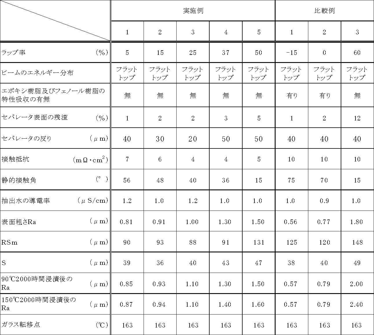
また、ラップ率60%の条件でレーザを照射して得られた比較例3の燃料電池セパレータでは、実施例1~5と同程度に照射表面の樹脂成分が除去されており、接触角も15°と高い親水性を有しているが、照射表面の表面粗さRaが1.8と高い値を示している。このことは、セパレータ表面から黒鉛粉が脱落し易くなっており、その結果、電極とセパレータとの接触面積が小さくなって接触抵抗が高くなったものと考えられる。
なお、実施例4で得られた燃料電池セパレータの表面のデジタル画像を図4に、それを画像処理し、茶色領域を抽出、二値化した画像を図5に示す。
一方、比較例3で得られた燃料電池セパレータでは、セパレータ表面の残渣が12%と高いため、溶出は少ないものの、熱水浸漬によって黒鉛粉が脱落し、粗さの変化が大きいことがわかる。
実施例1と同様の燃料電池セパレータ用組成物を調製し、これを同条件で成形して得られた成形体の表面に、波長1.06μmのファイバーレーザを、ラップ率35%の条件で、表2に示したレーザ出力条件にて照射して燃料電池セパレータを得た。
実施例1と同様の燃料電池セパレータ用組成物を調製し、これを同条件で成形して得られた成形体の表面に、波長1.06μmのYAGレーザを、ラップ率35%の条件で、表2に示したレーザ出力条件により照射して燃料電池セパレータを得た。

比較例5の条件でファイバーレーザを照射したセパレータは、パルス幅が250nsとパルスエネルギーが低いので、加工に時間がかかって加工中にセパレータが蓄熱されて反りが生じ、その結果、接触抵抗が高くなっていることがわかる。
比較例6の条件でファイバーレーザを照射したセパレータは、250Wと高出力であるため、加工中にセパレータが加熱されて反りが生じ、その結果、接触抵抗が高くなっていることがわかる。
比較例8の条件でYAGレーザを照射したセパレータは、パルス幅が50μsとパルスエネルギーが低いので、加工に時間がかかって加工中にセパレータが蓄熱されて反りが生じ、その結果、接触抵抗が高くなっていることがわかる。また、この場合も、図2,3に示されるように、セパレータ表面に樹脂の炭化物等の残渣が38%と多く存在し、90℃のイオン交換水に168時間浸漬させた後の導電率が4.2μS/cmと、溶出が多く、90℃のイオン交換水に2000時間浸漬させた後の表面粗さの変化も大きいことがわかる。
黒鉛粉末を、人造黒鉛粉末(平均粒径10μm(d50))に変更した以外は、実施例1と同様にして燃料電池セパレータ用組成物を調製し、成形体を得た。
得られた成形体のガス供給排出用流路となる溝が設けられた面に、実施例3と同様の条件でレーザを照射し、燃料電池セパレータを得た。
黒鉛粉末を、天然黒鉛粉末(平均粒径30μm(d50))に変更した以外は、実施例11と同様にして燃料電池セパレータを得た。
黒鉛粉末を、人造黒鉛粉末(平均粒径50μm(d50))に変更した以外は、実施例11と同様にして燃料電池セパレータを得た。
黒鉛粉末を、人造黒鉛粉末(平均粒径130μm(d50)に変更した以外は、実施例11と同様にして燃料電池セパレータを得た。

エポキシ樹脂をフェノールノボラック型エポキシ樹脂(エポキシ当量:183g/eq、ICI粘度:0.35Pa・s)15質量部に、ノボラック型フェノール樹脂の配合量を9質量部にそれぞれ変更した以外は、実施例1と同様にして燃料電池セパレータ用組成物を調製し、成形体を得た。
得られた成形体のガス供給排出用流路となる溝が設けられた面に、実施例3と同様の条件でレーザを照射し、燃料電池セパレータを得た。
エポキシ樹脂をフェノールノボラック型エポキシ樹脂(エポキシ当量:194g/eq、ICI粘度:0.53Pa・s)に変更した以外は、実施例15と同様にして燃料電池セパレータを得た。
エポキシ樹脂をo-クレゾールノボラック型エポキシ樹脂(エポキシ当量:199g/eq、ICI粘度:0.29Pa・s)に変更した以外は、実施例15と同様にして燃料電池セパレータを得た。
エポキシ樹脂をo-クレゾールノボラック型エポキシ樹脂(エポキシ当量:210g/eq、ICI粘度:0.8Pa・s)16質量部に、ノボラック型フェノール樹脂の配合量を8質量部にそれぞれ変更した以外は、実施例15と同様にして燃料電池セパレータを得た。

フェノール樹脂をノボラック型フェノール樹脂(水酸基当量:103g/eq、ICI粘度:0.16Pa・s)に変更した以外は、実施例1と同様にして燃料電池セパレータ用組成物を調製し、成形体を得た。
得られた成形体のガス供給排出用流路となる溝が設けられた面に、実施例3と同様の条件でレーザを照射し、燃料電池セパレータを得た。
フェノール樹脂をノボラック型フェノール樹脂(水酸基当量:104g/eq、ICI粘度:0.22Pa・s)に変更した以外は、実施例19と同様にして、燃料電池セパレータを得た。
フェノール樹脂をノボラック型フェノール樹脂(水酸基当量:105g/eq、ICI粘度:0.55Pa・s)に、エポキシ樹脂の配合量を16質量部にそれぞれ変更した以外は、実施例1と同様にして燃料電池セパレータ用組成物を調製し、成形体を得た。
得られた成形体のガス供給排出用流路となる溝が設けられた面に、実施例3と同様の条件でレーザを照射し、燃料電池セパレータを得た。
フェノール樹脂をノボラック型フェノール樹脂(水酸基当量:106g/eq、ICI粘度:0.67Pa・s)に変更した以外は、実施例21と同様にして燃料電池セパレータを得た。

Claims (7)
- 黒鉛粉末、エポキシ樹脂、フェノール樹脂、硬化促進剤および内部離型剤を含む組成物を成形してなる成形体の表面をレーザで照射して得られ、下記(1)~(6)の特性を備えることを特徴とする燃料電池セパレータ。
(1)表面のレーザ照射による残渣が、面積比で5%以下
(2)表面の算術平均粗さRa0.80~1.50μm
(3)表面の静的接触角15~60°
(4)表面の接触抵抗3~7mΩ・cm2
(5)イオン交換水:セパレータ=9:1(質量比)の条件で、セパレータをイオン交換水に90℃で168時間浸漬した後の導電率1.2μS/cm以下
(6)90℃のイオン交換水および150℃のイオン交換水のそれぞれに2000時間浸漬したときの表面粗さの変化が、浸漬前に対して0.3μm以内 - 表面局部山頂の平均間隔Sが、30~50μmである請求項1記載の燃料電池セパレータ。
- 反りが、100μm以下である請求項1または2記載の燃料電池セパレータ。
- 前記レーザの照射後の表面を全反射赤外吸光法(ATR)で分析して得られた赤外吸収スペクトルに、エポキシ樹脂およびフェノール樹脂に帰属する吸収帯が存在しない請求項1~3のいずれか1項記載の燃料電池セパレータ。
- 前記レーザの照射が、ラップ率5~50%で行われる請求項1~4のいずれか1項記載の燃料電池セパレータ。
- 前記レーザのエネルギー分布が、フラットトップである請求項1~5のいずれか1項記載の燃料電池セパレータ。
- 前記レーザが赤外線レーザである請求項1~6のいずれか1項記載の燃料電池セパレータ。
Priority Applications (5)
| Application Number | Priority Date | Filing Date | Title |
|---|---|---|---|
| US13/820,911 US20130171547A1 (en) | 2010-09-10 | 2011-08-22 | Fuel cell separator |
| CA2810309A CA2810309C (en) | 2010-09-10 | 2011-08-22 | Fuel cell separator |
| JP2012532924A JP5954177B2 (ja) | 2010-09-10 | 2011-08-22 | 燃料電池セパレータ |
| EP11823401.2A EP2615675B1 (en) | 2010-09-10 | 2011-08-22 | Fuel cell separator |
| KR1020137008335A KR101873534B1 (ko) | 2010-09-10 | 2011-08-22 | 연료전지 세퍼레이터 |
Applications Claiming Priority (2)
| Application Number | Priority Date | Filing Date | Title |
|---|---|---|---|
| JP2010-202846 | 2010-09-10 | ||
| JP2010202846 | 2010-09-10 |
Publications (1)
| Publication Number | Publication Date |
|---|---|
| WO2012032922A1 true WO2012032922A1 (ja) | 2012-03-15 |
Family
ID=45810525
Family Applications (1)
| Application Number | Title | Priority Date | Filing Date |
|---|---|---|---|
| PCT/JP2011/068822 WO2012032922A1 (ja) | 2010-09-10 | 2011-08-22 | 燃料電池セパレータ |
Country Status (6)
| Country | Link |
|---|---|
| US (1) | US20130171547A1 (ja) |
| EP (1) | EP2615675B1 (ja) |
| JP (1) | JP5954177B2 (ja) |
| KR (1) | KR101873534B1 (ja) |
| CA (1) | CA2810309C (ja) |
| WO (1) | WO2012032922A1 (ja) |
Cited By (6)
| Publication number | Priority date | Publication date | Assignee | Title |
|---|---|---|---|---|
| US20140093660A1 (en) * | 2012-10-03 | 2014-04-03 | Industrial Technology Research Institute | Method for manufacturing bipolar plate |
| WO2014129224A1 (ja) | 2013-02-25 | 2014-08-28 | 日清紡ケミカル株式会社 | 燃料電池セパレータ |
| JP2015532520A (ja) * | 2012-10-19 | 2015-11-09 | アウディ アクチェンゲゼルシャフトAudi Ag | 低コストの燃料セルコンポーネント |
| WO2017013994A1 (ja) * | 2015-07-22 | 2017-01-26 | 日清紡ケミカル株式会社 | 燃料電池セパレータの製造方法 |
| WO2019021966A1 (ja) * | 2017-07-25 | 2019-01-31 | 株式会社Ihi | 親水化材料、親水化部材及びそれを用いた気液接触装置 |
| JP2020509528A (ja) * | 2017-02-13 | 2020-03-26 | エルジー・ケム・リミテッド | 多孔体品質検査装置及び多孔体品質検査方法 |
Families Citing this family (6)
| Publication number | Priority date | Publication date | Assignee | Title |
|---|---|---|---|---|
| CN108026355B (zh) * | 2015-03-19 | 2020-05-12 | 衡所华威电子有限公司 | 环氧树脂组合物、其制备和用途 |
| JP6237805B2 (ja) * | 2016-03-15 | 2017-11-29 | 日清紡ケミカル株式会社 | 燃料電池用多孔質セパレータ |
| JP6760418B2 (ja) * | 2019-02-21 | 2020-09-23 | 日清紡ホールディングス株式会社 | 燃料電池セパレータ |
| FR3098357B1 (fr) * | 2019-07-01 | 2021-12-24 | Commissariat Energie Atomique | Procédé de fabrication d’un dispositif de diffusion gazeuse à propriétés électriques améliorées |
| DE102021113591A1 (de) | 2021-03-11 | 2022-09-15 | Schunk Kohlenstofftechnik Gmbh | Verfahren zum ausbilden einer hydrophilen oberfläche auf einem graphithaltigen werkstoff und verfahren zum fertigen einer bipolarplatte sowie bipolarplatte und brennstoffzelle bzw. flussbatterie mit derselben |
| US20240088405A1 (en) | 2021-03-11 | 2024-03-14 | Schunk Kohlenstofftechnik Gmbh | Method for forming a hydrophilic surface on a graphite-containing material, and method for manufacturing a bipolar plate, and bipolar plate, and fuel cell or flow battery having such a bipolar plate |
Citations (11)
| Publication number | Priority date | Publication date | Assignee | Title |
|---|---|---|---|---|
| JP2002060639A (ja) * | 2000-06-05 | 2002-02-26 | Showa Denko Kk | 導電性硬化性樹脂組成物、その硬化体、及びその成形体 |
| JP2003151574A (ja) * | 2001-11-19 | 2003-05-23 | Matsushita Electric Ind Co Ltd | 燃料電池用セパレータ及びその製造方法 |
| JP2004055458A (ja) * | 2002-07-23 | 2004-02-19 | Honda Motor Co Ltd | 燃料電池の製造方法 |
| JP2004335121A (ja) | 2003-04-30 | 2004-11-25 | Matsushita Electric Ind Co Ltd | 燃料電池とその製造方法 |
| JP2005197222A (ja) | 2003-12-12 | 2005-07-21 | Nisshinbo Ind Inc | 燃料電池セパレータ |
| JP2006066138A (ja) * | 2004-08-25 | 2006-03-09 | Matsushita Electric Ind Co Ltd | 燃料電池用セパレータ及びその製造方法及びそれを用いた固体高分子型燃料電池 |
| JP2006331673A (ja) | 2005-05-23 | 2006-12-07 | Nisshinbo Ind Inc | 燃料電池セパレータ |
| WO2007018185A1 (ja) * | 2005-08-05 | 2007-02-15 | Mitsubishi Pencil Co., Ltd. | 燃料電池用セパレータ及びその製造方法 |
| JP2007149467A (ja) * | 2005-11-25 | 2007-06-14 | Matsushita Electric Works Ltd | 燃料電池用セパレータとその製造方法 |
| JP4257544B2 (ja) | 2006-08-24 | 2009-04-22 | 日清紡績株式会社 | 固体高分子型燃料電池セパレータ |
| JP2009152176A (ja) | 2007-11-28 | 2009-07-09 | Seikoh Giken Co Ltd | 燃料電池用セパレータ及びその製造方法 |
Family Cites Families (9)
| Publication number | Priority date | Publication date | Assignee | Title |
|---|---|---|---|---|
| TW284907B (en) * | 1995-06-07 | 1996-09-01 | Cauldron Lp | Removal of material by polarized irradiation and back side application for radiation |
| US5961861A (en) * | 1996-01-15 | 1999-10-05 | The University Of Tennessee Research Corporation | Apparatus for laser alloying induced improvement of surfaces |
| CN1132258C (zh) * | 1997-11-07 | 2003-12-24 | 三洋电机株式会社 | 密闭式电池的制造方法及密闭式电池 |
| JP3739386B2 (ja) * | 2004-05-31 | 2006-01-25 | 松下電器産業株式会社 | 高分子電解質形燃料電池用セパレータ、高分子電解質形燃料電池、高分子電解質形燃料電池用セパレータの評価方法、及び、高分子電解質形燃料電池用セパレータの製造方法 |
| WO2005117180A1 (ja) * | 2004-05-31 | 2005-12-08 | Matsushita Electric Industrial Co., Ltd. | 高分子電解質形燃料電池用セパレータ、高分子電解質形燃料電池、高分子電解質形燃料電池用セパレータの評価方法、及び、高分子電解質形燃料電池用セパレータの製造方法 |
| JP4770268B2 (ja) * | 2005-05-23 | 2011-09-14 | トヨタ自動車株式会社 | 燃料電池システム |
| WO2007083731A1 (ja) * | 2006-01-23 | 2007-07-26 | Matsushita Electric Industrial Co., Ltd. | 密閉型電池 |
| US7442466B2 (en) * | 2006-01-31 | 2008-10-28 | Medtronic, Inc. | Access port for use in electrochemical cells |
| KR20090037355A (ko) * | 2007-10-11 | 2009-04-15 | 니찌아스 카부시키카이샤 | 연료전지용 세퍼레이터용 수지 조성물 및 연료전지용 세퍼레이터 |
-
2011
- 2011-08-22 US US13/820,911 patent/US20130171547A1/en not_active Abandoned
- 2011-08-22 WO PCT/JP2011/068822 patent/WO2012032922A1/ja active Application Filing
- 2011-08-22 CA CA2810309A patent/CA2810309C/en active Active
- 2011-08-22 EP EP11823401.2A patent/EP2615675B1/en active Active
- 2011-08-22 KR KR1020137008335A patent/KR101873534B1/ko active IP Right Grant
- 2011-08-22 JP JP2012532924A patent/JP5954177B2/ja active Active
Patent Citations (12)
| Publication number | Priority date | Publication date | Assignee | Title |
|---|---|---|---|---|
| JP2002060639A (ja) * | 2000-06-05 | 2002-02-26 | Showa Denko Kk | 導電性硬化性樹脂組成物、その硬化体、及びその成形体 |
| JP2003151574A (ja) * | 2001-11-19 | 2003-05-23 | Matsushita Electric Ind Co Ltd | 燃料電池用セパレータ及びその製造方法 |
| JP2004055458A (ja) * | 2002-07-23 | 2004-02-19 | Honda Motor Co Ltd | 燃料電池の製造方法 |
| JP2004335121A (ja) | 2003-04-30 | 2004-11-25 | Matsushita Electric Ind Co Ltd | 燃料電池とその製造方法 |
| JP2005197222A (ja) | 2003-12-12 | 2005-07-21 | Nisshinbo Ind Inc | 燃料電池セパレータ |
| JP2006066138A (ja) * | 2004-08-25 | 2006-03-09 | Matsushita Electric Ind Co Ltd | 燃料電池用セパレータ及びその製造方法及びそれを用いた固体高分子型燃料電池 |
| JP2006331673A (ja) | 2005-05-23 | 2006-12-07 | Nisshinbo Ind Inc | 燃料電池セパレータ |
| WO2007018185A1 (ja) * | 2005-08-05 | 2007-02-15 | Mitsubishi Pencil Co., Ltd. | 燃料電池用セパレータ及びその製造方法 |
| JP4148984B2 (ja) | 2005-08-05 | 2008-09-10 | 三菱鉛筆株式会社 | 燃料電池用セパレータ及びその製造方法 |
| JP2007149467A (ja) * | 2005-11-25 | 2007-06-14 | Matsushita Electric Works Ltd | 燃料電池用セパレータとその製造方法 |
| JP4257544B2 (ja) | 2006-08-24 | 2009-04-22 | 日清紡績株式会社 | 固体高分子型燃料電池セパレータ |
| JP2009152176A (ja) | 2007-11-28 | 2009-07-09 | Seikoh Giken Co Ltd | 燃料電池用セパレータ及びその製造方法 |
Non-Patent Citations (1)
| Title |
|---|
| See also references of EP2615675A4 |
Cited By (13)
| Publication number | Priority date | Publication date | Assignee | Title |
|---|---|---|---|---|
| US20140093660A1 (en) * | 2012-10-03 | 2014-04-03 | Industrial Technology Research Institute | Method for manufacturing bipolar plate |
| JP2015532520A (ja) * | 2012-10-19 | 2015-11-09 | アウディ アクチェンゲゼルシャフトAudi Ag | 低コストの燃料セルコンポーネント |
| US10651484B2 (en) | 2012-10-19 | 2020-05-12 | Audi Ag | Extruded carbon fuel cell components |
| US9768452B2 (en) | 2013-02-25 | 2017-09-19 | Nisshinbo Chemical Inc. | Fuel cell separator |
| WO2014129224A1 (ja) | 2013-02-25 | 2014-08-28 | 日清紡ケミカル株式会社 | 燃料電池セパレータ |
| WO2017013994A1 (ja) * | 2015-07-22 | 2017-01-26 | 日清紡ケミカル株式会社 | 燃料電池セパレータの製造方法 |
| JP2017027761A (ja) * | 2015-07-22 | 2017-02-02 | 日清紡ケミカル株式会社 | 燃料電池セパレータの製造方法 |
| JP2020509528A (ja) * | 2017-02-13 | 2020-03-26 | エルジー・ケム・リミテッド | 多孔体品質検査装置及び多孔体品質検査方法 |
| WO2019021966A1 (ja) * | 2017-07-25 | 2019-01-31 | 株式会社Ihi | 親水化材料、親水化部材及びそれを用いた気液接触装置 |
| JP2019022877A (ja) * | 2017-07-25 | 2019-02-14 | 株式会社Ihi | 親水化材料、親水化部材及びそれを用いた気液接触装置 |
| AU2018307001B2 (en) * | 2017-07-25 | 2021-03-11 | Ihi Corporation | Hydrophilized material, hydrophilized member, and gas-liquid contact apparatus in which same is used |
| US11014065B2 (en) | 2017-07-25 | 2021-05-25 | Ihi Corporation | Hydrophilized material, hydrophilized member, and gas-liquid contact apparatus in which same is used |
| JP7047273B2 (ja) | 2017-07-25 | 2022-04-05 | 株式会社Ihi | 親水化材料、親水化部材及びそれを用いた気液接触装置 |
Also Published As
| Publication number | Publication date |
|---|---|
| JPWO2012032922A1 (ja) | 2014-01-20 |
| EP2615675B1 (en) | 2019-07-24 |
| US20130171547A1 (en) | 2013-07-04 |
| KR20130115238A (ko) | 2013-10-21 |
| CA2810309C (en) | 2018-07-10 |
| CA2810309A1 (en) | 2012-03-15 |
| EP2615675A4 (en) | 2016-12-21 |
| EP2615675A1 (en) | 2013-07-17 |
| KR101873534B1 (ko) | 2018-07-03 |
| JP5954177B2 (ja) | 2016-07-20 |
Similar Documents
| Publication | Publication Date | Title |
|---|---|---|
| JP5954177B2 (ja) | 燃料電池セパレータ | |
| CN107851812B (zh) | 燃料电池隔板的制造方法 | |
| JP2008053052A (ja) | 固体高分子型燃料電池セパレータ | |
| JP5692256B2 (ja) | 燃料電池セパレータ | |
| WO2013047485A1 (ja) | 燃料電池用多孔質セパレータ | |
| JP5391005B2 (ja) | 燃料電池セパレータの製造方法及び燃料電池セパレータ | |
| CA2768958C (en) | Fuel cell separator | |
| CA2960454C (en) | Fuel cell separator | |
| JP5879553B2 (ja) | 燃料電池セパレータの製造方法、ガスケット付き燃料電池セパレータの製造方法、及び燃料電池の製造方法 | |
| JP6760418B2 (ja) | 燃料電池セパレータ | |
| JP5624298B2 (ja) | 燃料電池セパレータの製造方法及び燃料電池セパレータ | |
| JP6132247B2 (ja) | ガスケット付き燃料電池セパレータの製造方法 |
Legal Events
| Date | Code | Title | Description |
|---|---|---|---|
| 121 | Ep: the epo has been informed by wipo that ep was designated in this application |
Ref document number: 11823401 Country of ref document: EP Kind code of ref document: A1 |
|
| ENP | Entry into the national phase |
Ref document number: 2012532924 Country of ref document: JP Kind code of ref document: A |
|
| ENP | Entry into the national phase |
Ref document number: 2810309 Country of ref document: CA |
|
| WWE | Wipo information: entry into national phase |
Ref document number: 13820911 Country of ref document: US |
|
| NENP | Non-entry into the national phase |
Ref country code: DE |
|
| WWE | Wipo information: entry into national phase |
Ref document number: 2011823401 Country of ref document: EP |
|
| ENP | Entry into the national phase |
Ref document number: 20137008335 Country of ref document: KR Kind code of ref document: A |