WO2012020526A1 - 回路遮断器 - Google Patents
回路遮断器 Download PDFInfo
- Publication number
- WO2012020526A1 WO2012020526A1 PCT/JP2011/003241 JP2011003241W WO2012020526A1 WO 2012020526 A1 WO2012020526 A1 WO 2012020526A1 JP 2011003241 W JP2011003241 W JP 2011003241W WO 2012020526 A1 WO2012020526 A1 WO 2012020526A1
- Authority
- WO
- WIPO (PCT)
- Prior art keywords
- movable contact
- arc
- contact
- magnetic drive
- drive yoke
- Prior art date
Links
Images


Classifications
-
- H—ELECTRICITY
- H01—ELECTRIC ELEMENTS
- H01H—ELECTRIC SWITCHES; RELAYS; SELECTORS; EMERGENCY PROTECTIVE DEVICES
- H01H73/00—Protective overload circuit-breaking switches in which excess current opens the contacts by automatic release of mechanical energy stored by previous operation of a hand reset mechanism
- H01H73/02—Details
- H01H73/18—Means for extinguishing or suppressing arc
-
- H—ELECTRICITY
- H01—ELECTRIC ELEMENTS
- H01H—ELECTRIC SWITCHES; RELAYS; SELECTORS; EMERGENCY PROTECTIVE DEVICES
- H01H77/00—Protective overload circuit-breaking switches operated by excess current and requiring separate action for resetting
- H01H77/02—Protective overload circuit-breaking switches operated by excess current and requiring separate action for resetting in which the excess current itself provides the energy for opening the contacts, and having a separate reset mechanism
- H01H77/10—Protective overload circuit-breaking switches operated by excess current and requiring separate action for resetting in which the excess current itself provides the energy for opening the contacts, and having a separate reset mechanism with electrodynamic opening
- H01H77/107—Protective overload circuit-breaking switches operated by excess current and requiring separate action for resetting in which the excess current itself provides the energy for opening the contacts, and having a separate reset mechanism with electrodynamic opening characterised by the blow-off force generating means, e.g. current loops
- H01H77/108—Protective overload circuit-breaking switches operated by excess current and requiring separate action for resetting in which the excess current itself provides the energy for opening the contacts, and having a separate reset mechanism with electrodynamic opening characterised by the blow-off force generating means, e.g. current loops comprising magnetisable elements, e.g. flux concentrator, linear slot motor
-
- H—ELECTRICITY
- H01—ELECTRIC ELEMENTS
- H01H—ELECTRIC SWITCHES; RELAYS; SELECTORS; EMERGENCY PROTECTIVE DEVICES
- H01H9/00—Details of switching devices, not covered by groups H01H1/00 - H01H7/00
- H01H9/30—Means for extinguishing or preventing arc between current-carrying parts
- H01H9/44—Means for extinguishing or preventing arc between current-carrying parts using blow-out magnet
- H01H9/443—Means for extinguishing or preventing arc between current-carrying parts using blow-out magnet using permanent magnets
-
- H—ELECTRICITY
- H01—ELECTRIC ELEMENTS
- H01H—ELECTRIC SWITCHES; RELAYS; SELECTORS; EMERGENCY PROTECTIVE DEVICES
- H01H9/00—Details of switching devices, not covered by groups H01H1/00 - H01H7/00
- H01H9/30—Means for extinguishing or preventing arc between current-carrying parts
- H01H9/44—Means for extinguishing or preventing arc between current-carrying parts using blow-out magnet
- H01H9/446—Means for extinguishing or preventing arc between current-carrying parts using blow-out magnet using magnetisable elements associated with the contacts
-
- H—ELECTRICITY
- H01—ELECTRIC ELEMENTS
- H01H—ELECTRIC SWITCHES; RELAYS; SELECTORS; EMERGENCY PROTECTIVE DEVICES
- H01H1/00—Contacts
- H01H1/12—Contacts characterised by the manner in which co-operating contacts engage
- H01H1/14—Contacts characterised by the manner in which co-operating contacts engage by abutting
- H01H1/20—Bridging contacts
Definitions
- the present invention relates to a circuit breaker used for wiring protection, and more particularly to a circuit breaker having a direct acting two-contact structure.
- Patent Document 1 As a conventional circuit breaker, for example, there is a technique described in Patent Document 1.
- a U-shaped magnetic body is provided outside the movable contact and the fixed contact having different current paths.
- an electromagnetic repulsion force (Lorentz force) in a direction that repels between contacts when a large current such as a short circuit current flows, and a direction in which the movable contact is separated from the fixed contact It is possible to improve the shut-off performance.
- the arc generated between the contacts after opening the contacts can be moved to an arc extinguishing device disposed on both ends of the movable contact.
- an object of the present invention is to provide a circuit breaker that can appropriately move the arc between the contacts to the arc extinguishing device side even in a relatively small current region without increasing the size of the device.
- a first aspect of a circuit breaker according to the present invention includes a pair of front and rear fixed contacts arranged so as to face each other, and a direct acting type bridge that bridges the fixed contacts.
- a movable contact and a pair of front and rear magnetic drive yokes arranged so as to sandwich the side portions at both ends of the movable contact are provided at each pole, and the movable contact is pressed against the fixed contact by a contact spring.
- each pole energization path is closed, and the movable contact is pushed against the contact spring by an opening / closing mechanism, and is opened from the fixed contact to open the energization path.
- the magnetic drive yoke is formed of a permanent magnet.
- a permanent magnet is used as the magnetic drive yoke, a constant magnetic flux can be provided regardless of the magnitude of the current. Therefore, even in a relatively small current region, an arc generated between the contacts during the contact opening operation can be efficiently driven to the arc extinguishing device.
- the second aspect is characterized in that the magnetic drive yoke is made of a U-shaped permanent magnet, and is arranged so that both the leg portions sandwich the side surface portion of the movable contact.
- the magnetic drive yoke is composed of a U-shaped permanent magnet, the U-shaped leg portions can securely sandwich the side surfaces of both ends of the movable contact, and the magnetic drive yoke is disposed at a desired position. The degree of freedom of arrangement is great.
- a 3rd aspect is arrange
- a pair of bent U-shaped magnetic bodies, and the magnetic drive yoke is formed of a strip-shaped permanent magnet, and the lower surfaces thereof are fixed to the upper surfaces of both leg portions of the U-shaped magnetic body, The movable contactors are arranged so as to sandwich the side portions thereof, respectively.
- the magnetic drive yoke is composed of a strip-shaped permanent magnet
- the size of the permanent magnet can be reduced as compared with the case where it is composed of a U-shaped permanent magnet. Therefore, the cost can be reduced accordingly.
- the number of components can be reduced and the assembly of the circuit breaker can be simplified.
- a 4th aspect arrange
- the magnetic drive yoke is formed of a strip-shaped permanent magnet, and is fixed to the inner surfaces of both leg portions of the U-shaped magnetic body so that the side surface portion of the movable contact is It is characterized by being arranged so as to sandwich each of them.
- the strip-shaped permanent magnet is fixed to the inner surface of both legs of the U-shaped magnetic body formed by bending on the arc commutation plate, it is compared with the case where it is fixed to the tips of both legs of the U-shaped magnetic body.
- the leakage magnetic flux from the permanent magnet can be reduced.
- the arc generated between the contacts during the contact opening operation can be efficiently driven to the arc extinguishing device.
- the permanent magnet is used as the magnetic drive yoke, the arc generated around the energizing path when the contact is opened can be reliably moved to the arc extinguishing device side even in a relatively small current region. Therefore, it is possible to contribute to the provision of a small circuit breaker suitable for a DC circuit and the miniaturization of the product body, and to increase the number of parts shared with the AC exclusive product, so that a low-cost circuit breaker can be provided.
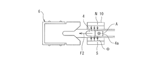
- FIG. 1 is a cross-sectional view showing a current interrupting part of a circuit breaker according to an embodiment of the present invention.
- the circuit breaker according to the present embodiment is a circuit breaker having a direct acting two-contact structure.
- reference numeral 1 denotes a current interrupting unit.
- U-shaped fixed contacts 2 and 3 made of a rectangular conductor are arranged facing each other in the front-rear direction, and fixed contacts 2a and 3a are attached to each.
- the strip-shaped movable contact 4 whose both ends are bent in a square shape has a pair of movable contacts 4a and 4b that can come into contact with the fixed contacts 2a and 3a, respectively.
- the movable contact 4 In the closed state in which the energization path is closed, the movable contact 4 is pressed toward the fixed contacts 2 and 3 by the contact spring 5 made of a compression spring, and the movable contacts 4a and 4b are in contact with the fixed contacts 2a and 3a, respectively.
- the fixed contacts 2 and 3 are bridged.
- the movable contact 4 is released from the fixed contacts 2 and 3 by being pushed down against the contact spring 5 by an opening / closing mechanism (not shown).
- a pair of arc extinguishing devices 6 are arranged before and after the movable contact 4, and a plurality of grids 7 surround both ends of the movable contact 4.
- the grid 7 is made of a U-shaped magnetic plate when viewed from above, and is supported by a pair of left and right insulator sidewalls 8.
- an arc commutation plate 9 made of a high resistance material such as a steel plate is provided below the arc extinguishing device 6 so as to straddle the front and rear arc extinguishing devices 6.
- the arc commutation plate 9 is a contact spring. 5 is also a receiving plate.
- reference numeral 10 denotes a pair of front and rear magnetic drive yokes made of U-shaped permanent magnets.
- the magnetic drive yoke 10 is arranged such that the left and right leg portions sandwich the side portions at both ends of the movable contact 4 respectively.
- one leg is the S pole and the other leg is the N pole, and they are arranged to have the polarities shown in FIG.
- the left and right leg portions of the magnetic drive yoke 10 are covered with an insulating cover 11.
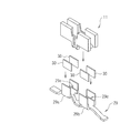
- FIG. 2 is an exploded perspective view showing the structure of the magnetic drive yoke portion including the arc commutation plate 9, the magnetic drive yoke 10, and the insulating cover 11.
- the insulating cover 11 is formed in a U shape having a pair of left and right side walls 11a and 11b by resin molding, and the movable contact 4 can be moved between the side walls 11a and 11b in the opening / closing direction (vertical direction in FIG. 1). Hold.
- bag-like portions each having an open bottom surface are formed. These bag-like portions are put on both leg portions 10a and 10b of the magnetic drive yoke 10 when the circuit breaker is assembled.
- the arc commutation plate 9 is disposed between the both leg portions 10a and 10b of the magnetic drive yoke 10 and outside the lower surface portion of the insulating cover 11 when the circuit breaker is assembled.
- FIGS. 3 is a cross-sectional view showing the structure of the current interrupting portion at the contact closing position
- FIG. 4 is a cross-sectional view of the vicinity of the contact
- FIG. 5 is a top view of the vicinity of the contact
- FIG. It is a figure which shows the advancing direction of an arc.
- an overcurrent detection device (not shown) detects an overcurrent and outputs a trip signal, and in response to this, the opening / closing mechanism pushes down the movable contact 4 downward in FIG.
- the stationary contacts 2a and 3a of the stationary contacts 2 and 3 and the movable contacts 4a and 4b of the movable contact 4 are pulled off. Therefore, the movable contact 4 is driven to open at a higher speed than that driven by the electromagnetic repulsion force alone or the opening / closing mechanism alone. Therefore, the blocking performance can be improved accordingly.
- an arc is generated between the fixed contacts 2 and 3 and the movable contact 4 during the contact opening operation in which the fixed contacts 2 a and 3 a and the movable contacts 4 a and 4 b are detached.
- this arc A is orthogonal to the magnetic flux (magnetic flux passing from the left to the right in FIG. 4) ⁇ strengthened by the magnetic drive yoke 10, so that the arc A is movable contacted by Fleming's left-hand rule.
- a force F2 directed outward in the front-rear direction of the child 4 acts.
- the arc A generated between the contacts is, as shown in FIG.
- FIG. 13 is a diagram illustrating a structure of a current interrupting unit of a conventional circuit breaker, in which (a) is a top view of the current interrupting unit and (b) is a front view of the current interrupting unit.
- the magnetic drive yoke 110 made of a magnetic material is formed integrally with the arc commutation plate 109 is shown. That is, the pair of front and rear magnetic drive yokes 110 are formed integrally with the arc commutation plate 109 and extend upright in the opening movement direction of the movable contact 104.
- the pair of front and rear magnetic drive yokes are disposed so as to sandwich the side portions at both ends of the movable contact, respectively, so that when the current flows through the movable contact in a closed state, the fixed contact is secured.
- a strong electromagnetic repulsive force (Lorentz force) is generated between the contact and the movable contact, and the movable contact can be driven in a direction to separate from the fixed contact. Further, during the contact opening operation, the arc generated between the contacts can be driven in the direction of the arc extinguishing device by Lorentz force.
- the magnetic drive yoke is composed of a U-shaped permanent magnet, the side portions at both ends of the movable contact can be reliably sandwiched between the U-shaped legs. Further, since the magnetic drive yoke is a single member, the arc commutation plate can be formed in a strip shape, and the arc commutation plate can be easily formed as compared with the case where it is configured integrally with the arc commutation plate. In addition, the degree of freedom of the arrangement of the magnetic drive yoke can be increased. Further, in the contact opening operation process, the contact point is filled with high-pressure conductive gas generated by the arc. By completely covering these with an insulating cover, it is possible to prevent a short circuit between the magnetic drive yokes from occurring.
- FIG. 7 is a cross-sectional view showing the structure of the current interrupting unit 1 of the second embodiment.
- the current interrupting unit 1 of this embodiment is different from the current interrupting unit 1 of FIG. 1 except that the configuration of the magnetic drive yoke unit is different from that of the current interrupting unit 1 shown in FIG. It has the same configuration. Therefore, parts having the same configuration as in FIG. 1 are denoted by the same reference numerals, and here, different parts will be mainly described.
- an arc commutation plate 19 is used instead of the arc commutation plate 9
- a strip-shaped magnetic drive yoke 20 is used instead of the magnetic drive yoke 10.
- FIG. 8 is an exploded perspective view showing the structure of the magnetic drive yoke portion of the second embodiment.
- U-shaped magnetic bodies 19 a and 19 b that are bent to the movable contact 4 side are formed at both end positions of the movable contact 4 in the longitudinal direction of the arc commutation plate 19.
- the magnetic drive yoke 20 is made of a strip-shaped permanent magnet, and its lower surface is fixed to the upper surfaces of both leg portions of the U-shaped magnetic bodies 19a and 19b of the arc commutation plate 19, thereby It is constructed integrally.
- the magnetic drive yoke 20 is arranged so that different magnetic poles face each other in the width direction (left-right direction) of the movable contact 4 so as to have the polarity shown in FIG.
- the U-shaped magnetic bodies 19a and 19b and the magnetic drive yoke 20 are fixed with the magnetic drive yokes 20 fixed to the upper surfaces of both leg portions of the U-shaped magnetic bodies 19a and 19b formed on the arc commutation plate 19.
- the insulating cover 11 having the same configuration as that of the first embodiment described above is covered.
- the side surface portion of the movable contact 4 is sandwiched between the magnetic drive yokes 20 fixed to both leg portions of the U-shaped magnetic bodies 19a and 19b. That is, both leg portions of the U-shaped magnetic bodies 19 a and 19 b are formed to be short enough to arrange the magnetic drive yoke 20 in the movable range of the movable contact 4.
- the arc A moves to the arc extinguishing device 6 disposed on both ends of the movable contact 4.
- the magnetic drive yoke is fixed to the upper surfaces of both legs of the U-shaped magnetic body formed on the arc commutation plate, whereas the U-shaped magnetic body. It is made to fix to the inner surface of both legs.
- FIG. 10 is an exploded perspective view showing the structure of the magnetic drive yoke portion of the third embodiment.
- U-shaped magnetic bodies 29 a and 29 b that are bent to the movable contact side are formed at both end positions of the movable contact 4 in the front-rear direction of the arc commutation plate 29.
- a stepped portion 29c for fixing the magnetic drive yoke 30 is formed inside both the leg portions of the U-shaped magnetic bodies 29a and 29b.
- the magnetic drive yoke 30 is made of a strip-shaped permanent magnet having a thickness equivalent to that of the stepped portion 29c, and is fixed to the stepped portion 29c formed on the arc commutating plate 29 so as to be integrated with the arc commutating plate 29. Constructed. That is, the magnetic drive yoke 30 is fixed to the inner surfaces of both leg portions of the U-shaped magnetic bodies 29a and 29b. At this time, the magnetic drive yoke 30 is arranged so that different magnetic poles face each other in the width direction (left-right direction) of the movable contact 4 so as to have the polarity shown in FIG.
- the U-shaped magnetic bodies 29a and 29b and the magnetic drive yoke 30 are attached to the first and second U-shaped magnetic bodies 29a and 29b in a state where the magnetic drive yoke 30 is fixed to the stepped portion 29c formed in the arc commutation plate 29.
- the insulating cover 11 having the same configuration as that of the second embodiment is covered.
- the side surface portion of the movable contact 4 is sandwiched between the magnetic drive yokes 30 fixed to both leg portions of the U-shaped magnetic bodies 29a and 29b. That is, both leg portions of the U-shaped magnetic bodies 29 a and 29 b are formed long enough to place the magnetic drive yoke 30 in the movable range of the movable contact 4.
- the magnetic drive yoke 30 made of a permanent magnet is fixed to the inner surfaces of both leg portions of the U-shaped magnetic bodies 29a and 29b.
- the U-shaped magnetic bodies 29a and 29b are arranged outside the magnetic drive yoke 30 made of a permanent magnet. Therefore, the leakage magnetic flux ⁇ ′ from the permanent magnet as shown in FIG. 12 can be reduced, and the electromagnetic force for driving the arc A generated between the contacts to the arc extinguishing device 6 side is efficiently generated accordingly. Can be made.
- the magnetic drive yoke is integrally formed with the arc commutation plate, assembly of the circuit breaker and component management are facilitated.
- the magnetic drive yoke has a strip shape, the size of the permanent magnet can be reduced compared with the U-shaped magnetic drive yoke in the first embodiment described above, and the cost can be reduced accordingly. Can do.
- the magnetic drive yoke is fixed to the inner surfaces of both legs of the U-shaped magnetic body of the arc commutation plate, the leakage magnetic flux from the permanent magnet can be reduced, and the arc generated between the contacts is directed to the arc extinguishing device side. It can be moved efficiently.
- the magnetic drive yoke is fixed to the stepped portion formed on the U-shaped magnetic body of the arc commutation plate, the thickness of the permanent magnet is reduced compared to the magnetic drive yoke of the second embodiment described above. And the cost can be reduced accordingly. Furthermore, since the magnetic drive yoke can be attracted to the stepped portion, the positioning of the magnetic drive yoke is facilitated as compared with the case where the magnetic drive yoke is fixed to the inner surfaces of both legs of the U-shaped magnetic body without a step. Assembling property can be simplified.
- circuit breaker According to the circuit breaker according to the present invention, it is possible to contribute to the provision of a small circuit breaker suitable for a DC circuit and the miniaturization of the product main body, and it is possible to increase the number of parts shared with an AC-dedicated product. Can be provided and useful.
Abstract
Description
したがって、低い電流領域では、接点開極時に発生したアークを消弧装置へ移動させる力が不足してしまう。このため、電流遮断時(接点開極動作時)に接点間に発生したアークは両接点間の短い距離で停滞した状態で遮断しなければならず、電流零点を持たない直流回路で高電圧に対応するためには、より多くの接点開極距離を必要とする。その結果、消弧装置並びに製品が大型化するなどの問題がある。
そこで、本発明は、装置の大型化を伴うことなく、比較的小さい電流領域でも適切に接点間のアークを消弧装置側へ移動させることができる回路遮断器を提供することを課題としている。
このように、磁気駆動ヨークをU字形の永久磁石により構成するので、U字形の両脚部によって確実に可動接触子の両端の側面部を挟むことができると共に、磁気駆動ヨークを所望の位置に配置することができるので、配置の自由度が大きい。
(第1の実施形態)
(構成)
図1は、本発明の実施形態に係る回路遮断器の電流遮断部を示す断面図である。ここで、本実施形態に係る回路遮断器は、直動2接点構造を持つ回路遮断器である。
絶縁カバー11は、樹脂成形により左右一対の側壁11a,11bを有するU字形に形成されており、可動接触子4を側壁11a,11bの間で開閉方向(図1の上下方向)に移動可能に保持する。この絶縁カバー11の側壁11a,11bには、それぞれ下面が開口した袋状部が形成されている。これら袋状部は、回路遮断器の組み立て時において、磁気駆動ヨーク10の両脚部10a,10bに被せられる。また、アーク転流板9は、回路遮断器の組み立て時において、磁気駆動ヨーク10の両脚部10a,10bの間で、且つ絶縁カバー11の下面部外側に配置される。
次に、第1の実施形態の動作について、図3~図6を参照しながら説明する。
ここで、図3は接点閉極位置における電流遮断部の構造を示す断面図、図4は接点近傍断面図、図5は接点近傍上面図、図6は接点開極位置における電流遮断部構造とアークの進行方向とを示す図である。
そのため、可動接触子4は、電磁反発力単独又は開閉機構単独で駆動するものよりも大きい速度で開極駆動される。したがって、それだけ遮断性能を向上させることができる。
その際、アーク転流板9を設けているため、アークAの可動接触子4側の足はアーク転流板9に移り、アークAは電流が可動接触子4を流れない状態で消弧されて、大電流による可動接触子4の損傷が抑えられる。
図13は、従来の回路遮断器の電流遮断部の構造を示す図であり、(a)は電流遮断部の上面図、(b)は電流遮断部の正面図である。ここでは、アーク転流板109と一体に磁性体からなる磁気駆動ヨーク110を形成した例を示している。すなわち、前後一対の磁気駆動ヨーク110は、アーク転流板109に一体に折り曲げ形成され、可動接触子104の開極移動方向に起立延在している。
以上のように、より広い範囲の電流領域で回路遮断器が持つ消弧装置を効率良く使用した電流遮断が可能となる。
このように、第1の実施形態では、可動接触子の両端の側面部をそれぞれ挟むように前後一対の磁気駆動ヨークを配置するので、閉極状態で可動接触子に電流が流れたとき、固定接触子と可動接触子との間に強い電磁反発力(ローレンツ力)を発生させて、可動接触子を固定接触子から開離する方向へ駆動させることができる。また、接点開極動作時には、接点間に発生したアークをローレンツ力により消弧装置方向へ駆動することができる。
したがって、従来構造では対応が困難であった低電流領域の直流遮断において、確実に消弧装置を使用した広範囲の電流遮断が可能となる。そのため、直流回路に適した小形消弧装置の提供と製品本体の小型化に寄与でき、交流専用品との部品共用化を多くできることから、低コストな回路遮断器を実現することができる。
さらに、接点開極動作過程において、接点近傍にはアークによって発生した高圧力の導電性ガスが充満するが、磁気駆動ヨークの両脚部を絶縁カバーで完全に覆うことで、磁気駆動ヨーク同士の相間短絡が発生するのを防止することができる。
次に、本発明の第2の実施形態について説明する。
この第2の実施形態は、前述した第1の実施形態において、U字形の磁気駆動ヨーク10を適用しているのに対し、磁気駆動ヨーク10をアーク転流板9に一体的に構成するようにしたものである。
図7は、第2の実施形態の電流遮断部1の構造を示す断面図である。
この図7に示すように、本実施形態の電流遮断部1は、図1に示す電流遮断部1において、磁気駆動ヨーク部の構成が異なることを除いては、図1の電流遮断部1と同様の構成を有する。したがって、図1と同様の構成を有する部分には同一符号を付し、ここでは構成の異なる部分を中心に説明する。
本実施形態では、アーク転流板9に代えてアーク転流板19を用いると共に、磁気駆動ヨーク10に代えて、短冊状の磁気駆動ヨーク20を用いる。
この図8に示すように、アーク転流板19の前後方向における可動接触子4の両端位置には、それぞれ可動接触子4側に折り曲げ成形されたU字形磁性体19a,19bが形成されている。
また、磁気駆動ヨーク20は短冊形の永久磁石からなり、その下面が、アーク転流板19のU字形磁性体19a,19bの両脚部の上面に固定されることで、アーク転流板19と一体的に構成される。このとき、磁気駆動ヨーク20は、可動接触子4の幅方向(左右方向)において、図9に示す極性となるように、異なる磁極が対向するように配置する。
これにより、U字形磁性体19a,19bの両脚部にそれぞれ固定された磁気駆動ヨーク20によって可動接触子4の側面部を挟む。すなわち、U字形磁性体19a,19bの両脚部は、可動接触子4の可動範囲に磁気駆動ヨーク20が配置される程度に短く形成する。
次に、第2の実施形態の動作について説明する。
閉極状態において、短絡電流のような大電流Iが流れ、固定接触子2及び3の固定接点2a及び3aと、可動接触子4の可動接点4a及び4bとが引き外されると、固定接触子2及び3と可動接触子4との間にはアークが発生する。
このアークAは、図9に示すように、磁気駆動ヨーク20によって強められた磁束Φと鎖交するため、アークAには可動接触子4の前後方向外側へ向かう力F2が働く。これにより、このアークAは、可動接触子4の両端側に配置された消弧装置6まで移動する。
このように、上述した第1の実施形態と同様に、接点開極時に通電路の周囲に発生したアークを適切に消弧装置側へ移動させることができる。
このように、第2の実施形態では、磁気駆動ヨークをアーク転流板と一体的に構成するので、回路遮断器の組み立てや部品管理が容易となる。
また、磁気駆動ヨークを短冊形とするので、上述した第1の実施形態におけるU字形の磁気駆動ヨークと比較して、永久磁石の大きさを小さくすることができ、その分コストを削減することができる。
次に、本発明の第3の実施形態について説明する。
この第3の実施形態は、前述した第2の実施形態において、磁気駆動ヨークをアーク転流板に形成したU字形磁性体の両脚部の上面に固定しているのに対し、U字形磁性体の両脚部の内側表面に固定するようにしたものである。
本実施形態の電流遮断部1は、図8に示す電流遮断部1において、磁気駆動ヨーク部の構成が異なることを除いては、図8の電流遮断部1と同様の構成を有する。したがって、ここでは構成の異なる部分を中心に説明する。
図10は、第3の実施形態の磁気駆動ヨーク部の構造を示す分解斜視図である。
この図10に示すように、アーク転流板29の前後方向における可動接触子4の両端位置には、それぞれ可動接触子側に折り曲げ成形されたU字形磁性体29a,29bが形成されている。また、これらU字形磁性体29a,29bの両脚部内側には、磁気駆動ヨーク30を固定するための段差部29cが形成されている。
これにより、U字形磁性体29a,29bの両脚部にそれぞれ固定された磁気駆動ヨーク30によって可動接触子4の側面部を挟む。すなわち、U字形磁性体29a,29bの両脚部は、可動接触子4の可動範囲に磁気駆動ヨーク30が配置される程度に長く形成する。
次に、第3の実施形態の動作について説明する。
閉極状態において、短絡電流のような大電流Iが流れ、固定接触子2及び3の固定接点2a及び3aと、可動接触子4の可動接点4a及び4bとが引き外されると、固定接触子2及び3と可動接触子4との間にはアークが発生する。
このアークAは、図11に示すように、磁気駆動ヨーク30によって強められた磁束Φと鎖交するため、アークAには可動接触子4の前後方向外側へ向かう力F2が働く。これにより、このアークAは、可動接触子4の両端側に配置された消弧装置6まで移動する。
ところで、第2の実施形態のように、アーク転流板19に形成されたU字形磁性体19a,19bの両脚部上面に磁気駆動ヨーク30を固定する構成の場合、図12に示すように、永久磁石からの漏れ磁束Φ´が発生する。そのため、接点間に発生するアークAを消弧装置6側へ駆動させるための電磁力を効率的に発生させることができない。
このように、第3の実施形態では、磁気駆動ヨークをアーク転流板と一体的に構成するので、回路遮断器の組み立てや部品管理が容易となる。
また、磁気駆動ヨークを短冊形とするので、上述した第1の実施形態におけるU字形の磁気駆動ヨークと比較して、永久磁石の大きさを小さくすることができ、その分コストを削減することができる。
さらに、磁気駆動ヨークをアーク転流板のU字形磁性体の両脚部の内側表面に固定するので、永久磁石からの漏れ磁束を減らすことができ、接点間に発生するアークを消弧装置側へ効率良く移動させることができる。
Claims (4)
- 互いに対向するように配置された前後一対の固定接触子と、前記固定接触子を橋絡する直動式の可動接触子と、前記可動接触子の両端の側面部をそれぞれ挟むようにして配置される前後一対の磁気駆動ヨークと、を各極に有し、
前記可動接触子が接触スプリングにより前記固定接触子に押圧されることで各極通電路を閉路すると共に、前記可動接触子が開閉機構により前記接触スプリングに抗して押され、前記固定接触子から開離することで前記通電路を開路するように構成されており、
前記磁気駆動ヨークは、永久磁石からなることを特徴とする回路遮断器。 - 前記磁気駆動ヨークは、U字形の永久磁石からなり、両脚部で前記可動接触子の前記側面部をそれぞれ挟むようにして配置されることを特徴とする請求項1に記載の回路遮断器。
- 前記可動接触子の前後に配置された一対の消弧装置と、これらの消弧装置間に跨がるように前記可動接触子の下方に配置され、電流遮断時に前記固定接触子と前記可動接触子との間に発生するアークの前記可動接触子側の足を転流させるアーク転流板と、を備え、
前記アーク転流板は、前記可動接触子側に折り曲げ形成された一対のU字形磁性体を有しており、
前記磁気駆動ヨークは、短冊形の永久磁石からなり、その下面が前記U字形磁性体の両脚部上面に固定されることで、前記可動接触子の前記側面部をそれぞれ挟むようにして配置されることを特徴とする請求項1に記載の回路遮断器。 - 前記可動接触子の前後に配置された一対の消弧装置と、これらの消弧装置間に跨がるように前記可動接触子の下方に配置され、電流遮断時に前記固定接触子と前記可動接触子との間に発生するアークの前記可動接触子側の足を転流させるアーク転流板と、を備え、
前記アーク転流板は、前記可動接触子側に折り曲げ形成された一対のU字形磁性体を有しており、
前記磁気駆動ヨークは、短冊形の永久磁石からなり、前記U字形磁性体の両脚部の内側表面に固定されることで、前記可動接触子の前記側面部をそれぞれ挟むようにして配置されることを特徴とする請求項1に記載の回路遮断器。
Priority Applications (3)
| Application Number | Priority Date | Filing Date | Title |
|---|---|---|---|
| CN2011800392002A CN103069532A (zh) | 2010-08-12 | 2011-06-08 | 断路器 |
| KR1020137003569A KR101377342B1 (ko) | 2010-08-12 | 2011-06-08 | 회로 차단기 |
| EP11816196.7A EP2605265A4 (en) | 2010-08-12 | 2011-06-08 | BREAKERS |
Applications Claiming Priority (2)
| Application Number | Priority Date | Filing Date | Title |
|---|---|---|---|
| JP2010180988A JP2012043541A (ja) | 2010-08-12 | 2010-08-12 | 回路遮断器 |
| JP2010-180988 | 2010-08-12 |
Publications (1)
| Publication Number | Publication Date |
|---|---|
| WO2012020526A1 true WO2012020526A1 (ja) | 2012-02-16 |
Family
ID=45567502
Family Applications (1)
| Application Number | Title | Priority Date | Filing Date |
|---|---|---|---|
| PCT/JP2011/003241 WO2012020526A1 (ja) | 2010-08-12 | 2011-06-08 | 回路遮断器 |
Country Status (6)
| Country | Link |
|---|---|
| EP (1) | EP2605265A4 (ja) |
| JP (1) | JP2012043541A (ja) |
| KR (1) | KR101377342B1 (ja) |
| CN (1) | CN103069532A (ja) |
| TW (1) | TWI446392B (ja) |
| WO (1) | WO2012020526A1 (ja) |
Cited By (2)
| Publication number | Priority date | Publication date | Assignee | Title |
|---|---|---|---|---|
| CN114388313A (zh) * | 2021-12-24 | 2022-04-22 | 上海京硅智能技术有限公司 | 直动式断路器 |
| JP7399308B2 (ja) | 2020-03-13 | 2023-12-15 | エルエス、エレクトリック、カンパニー、リミテッド | 気中遮断器 |
Families Citing this family (15)
| Publication number | Priority date | Publication date | Assignee | Title |
|---|---|---|---|---|
| JP6066598B2 (ja) | 2012-07-04 | 2017-01-25 | 富士通コンポーネント株式会社 | 電磁継電器 |
| JP6044927B2 (ja) * | 2012-09-13 | 2016-12-14 | パナソニックIpマネジメント株式会社 | 直流開閉器および直流遮断器 |
| KR101698421B1 (ko) * | 2012-12-06 | 2017-01-20 | 후지 덴키 기기세이교 가부시끼가이샤 | 접점 장치 및 이것을 사용한 전자 개폐기 |
| JP6342724B2 (ja) * | 2014-06-13 | 2018-06-13 | 富士電機株式会社 | 回路遮断器 |
| AU2015356244B2 (en) * | 2014-12-01 | 2018-02-15 | Mitsubishi Electric Corporation | DC high-speed circuit breaker |
| DE102015000796B4 (de) * | 2015-01-22 | 2017-03-02 | Schaltbau Gmbh | Schaltgerät mit permanentmagnetischer Lichtbogenlöschung |
| US9552951B2 (en) | 2015-03-06 | 2017-01-24 | Cooper Technologies Company | High voltage compact fusible disconnect switch device with magnetic arc deflection assembly |
| US9601297B2 (en) | 2015-03-23 | 2017-03-21 | Cooper Technologies Company | High voltage compact fuse assembly with magnetic arc deflection |
| US9406465B1 (en) * | 2015-07-30 | 2016-08-02 | Carling Technologies, Inc. | Polarity insensitive arc quench |
| US10854414B2 (en) | 2016-05-11 | 2020-12-01 | Eaton Intelligent Power Limited | High voltage electrical disconnect device with magnetic arc deflection assembly |
| JP6599030B2 (ja) * | 2017-07-26 | 2019-10-30 | 三菱電機株式会社 | 開閉器 |
| US10211003B1 (en) * | 2017-11-22 | 2019-02-19 | Carling Technologies, Inc. | Single pole DC circuit breaker with bi-directional arc chamber |
| US10636607B2 (en) | 2017-12-27 | 2020-04-28 | Eaton Intelligent Power Limited | High voltage compact fused disconnect switch device with bi-directional magnetic arc deflection assembly |
| CN114946007A (zh) * | 2020-01-23 | 2022-08-26 | 三菱电机株式会社 | 开闭器 |
| KR20210115323A (ko) | 2020-03-12 | 2021-09-27 | 엘에스일렉트릭(주) | 베이스 조립체 및 이를 포함하는 배선용 차단기 |
Citations (3)
| Publication number | Priority date | Publication date | Assignee | Title |
|---|---|---|---|---|
| JPS5914219A (ja) * | 1982-07-16 | 1984-01-25 | 富士電機株式会社 | 直流電磁接触器 |
| JPH10154458A (ja) * | 1996-11-25 | 1998-06-09 | Matsushita Electric Works Ltd | 直流遮断器 |
| JP3859053B2 (ja) | 2000-07-07 | 2006-12-20 | 富士電機機器制御株式会社 | 回路遮断器 |
Family Cites Families (9)
| Publication number | Priority date | Publication date | Assignee | Title |
|---|---|---|---|---|
| US4013984A (en) * | 1975-08-22 | 1977-03-22 | Westinghouse Electric Corporation | Current limiting circuit breaker |
| JPH01319217A (ja) * | 1988-06-20 | 1989-12-25 | Fuji Electric Co Ltd | 開閉機器の消弧室 |
| ZA896375B (en) * | 1988-09-12 | 1990-05-30 | Westinghouse Electric Corp | Circuit breaker with arc gun |
| FR2687251B1 (fr) * | 1992-02-11 | 1994-04-29 | Telemecanique | Structure de coupure pour disjoncteur. |
| JP2965025B1 (ja) * | 1998-04-07 | 1999-10-18 | 富士電機株式会社 | 回路遮断器 |
| DE60019912T2 (de) * | 1999-10-14 | 2006-01-12 | Matsushita Electric Works, Ltd., Kadoma | Kontaktvorrichtung |
| DE10343005B4 (de) * | 2003-09-17 | 2005-10-27 | Siemens Ag | Schaltgerät sowie Verfahren zu dessen Herstellung |
| JP2005216807A (ja) * | 2004-02-02 | 2005-08-11 | Fuji Electric Fa Components & Systems Co Ltd | 回路遮断器 |
| JP4419642B2 (ja) | 2004-03-30 | 2010-02-24 | 富士電機機器制御株式会社 | 回路遮断器の消弧装置 |
-
2010
- 2010-08-12 JP JP2010180988A patent/JP2012043541A/ja active Pending
-
2011
- 2011-06-08 EP EP11816196.7A patent/EP2605265A4/en not_active Withdrawn
- 2011-06-08 KR KR1020137003569A patent/KR101377342B1/ko not_active IP Right Cessation
- 2011-06-08 WO PCT/JP2011/003241 patent/WO2012020526A1/ja active Application Filing
- 2011-06-08 CN CN2011800392002A patent/CN103069532A/zh active Pending
- 2011-08-04 TW TW100127728A patent/TWI446392B/zh not_active IP Right Cessation
Patent Citations (3)
| Publication number | Priority date | Publication date | Assignee | Title |
|---|---|---|---|---|
| JPS5914219A (ja) * | 1982-07-16 | 1984-01-25 | 富士電機株式会社 | 直流電磁接触器 |
| JPH10154458A (ja) * | 1996-11-25 | 1998-06-09 | Matsushita Electric Works Ltd | 直流遮断器 |
| JP3859053B2 (ja) | 2000-07-07 | 2006-12-20 | 富士電機機器制御株式会社 | 回路遮断器 |
Non-Patent Citations (1)
| Title |
|---|
| See also references of EP2605265A4 * |
Cited By (3)
| Publication number | Priority date | Publication date | Assignee | Title |
|---|---|---|---|---|
| JP7399308B2 (ja) | 2020-03-13 | 2023-12-15 | エルエス、エレクトリック、カンパニー、リミテッド | 気中遮断器 |
| CN114388313A (zh) * | 2021-12-24 | 2022-04-22 | 上海京硅智能技术有限公司 | 直动式断路器 |
| CN114388313B (zh) * | 2021-12-24 | 2024-03-12 | 上海京硅智能技术有限公司 | 直动式断路器 |
Also Published As
| Publication number | Publication date |
|---|---|
| JP2012043541A (ja) | 2012-03-01 |
| EP2605265A1 (en) | 2013-06-19 |
| KR101377342B1 (ko) | 2014-03-25 |
| CN103069532A (zh) | 2013-04-24 |
| EP2605265A4 (en) | 2014-09-10 |
| TWI446392B (zh) | 2014-07-21 |
| KR20130044319A (ko) | 2013-05-02 |
| TW201230118A (en) | 2012-07-16 |
Similar Documents
| Publication | Publication Date | Title |
|---|---|---|
| WO2012020526A1 (ja) | 回路遮断器 | |
| US9378914B2 (en) | Contact device and electromagnetic contactor using the same | |
| WO2012160732A1 (ja) | 回路遮断器 | |
| JP5522327B2 (ja) | 回路遮断器 | |
| JP5084982B1 (ja) | 直流回路用回路遮断器及び直流回路用回路遮断装置 | |
| KR101568685B1 (ko) | 직류 개폐기의 소호 기구, 및 상기 소호 기구를 가지는 직류 개폐기 및 직류 차단기 | |
| EP2980821A1 (en) | Switchgear | |
| JP5515719B2 (ja) | 回路遮断器 | |
| KR20150141866A (ko) | 회로 차단기 | |
| KR101232453B1 (ko) | 회로차단기 | |
| US20120006791A1 (en) | Arc extinguishing mechanism for mold cased circuit breaker | |
| JP2012221701A (ja) | 回路遮断器 | |
| KR101565454B1 (ko) | 직류 개폐기 및 직류 차단기 | |
| JP4542025B2 (ja) | 回路遮断器 | |
| JP4090948B2 (ja) | 回路遮断器 | |
| JP2015028904A (ja) | 回路遮断器 | |
| JP5475566B2 (ja) | 回路遮断器 | |
| JP7248955B2 (ja) | 回路用遮断器 | |
| JP2012221759A (ja) | 回路遮断器 | |
| JP5488353B2 (ja) | 回路遮断器 | |
| WO2020202558A1 (ja) | 回路遮断器 | |
| JP2012059585A (ja) | 回路遮断器 | |
| JP2012150986A (ja) | 回路遮断器 | |
| JP2012043565A (ja) | 回路遮断器 |
Legal Events
| Date | Code | Title | Description |
|---|---|---|---|
| WWE | Wipo information: entry into national phase |
Ref document number: 201180039200.2 Country of ref document: CN |
|
| 121 | Ep: the epo has been informed by wipo that ep was designated in this application |
Ref document number: 11816196 Country of ref document: EP Kind code of ref document: A1 |
|
| DPE1 | Request for preliminary examination filed after expiration of 19th month from priority date (pct application filed from 20040101) | ||
| ENP | Entry into the national phase |
Ref document number: 20137003569 Country of ref document: KR Kind code of ref document: A |
|
| NENP | Non-entry into the national phase |
Ref country code: DE |
|
| WWE | Wipo information: entry into national phase |
Ref document number: 2011816196 Country of ref document: EP |