WO2012018043A1 - ナノインプリント用樹脂製モールド - Google Patents
ナノインプリント用樹脂製モールド Download PDFInfo
- Publication number
- WO2012018043A1 WO2012018043A1 PCT/JP2011/067765 JP2011067765W WO2012018043A1 WO 2012018043 A1 WO2012018043 A1 WO 2012018043A1 JP 2011067765 W JP2011067765 W JP 2011067765W WO 2012018043 A1 WO2012018043 A1 WO 2012018043A1
- Authority
- WO
- WIPO (PCT)
- Prior art keywords
- resin
- nanoimprinting
- resin mold
- mold
- macromonomer
- Prior art date
Links
Images


Classifications
-
- B—PERFORMING OPERATIONS; TRANSPORTING
- B29—WORKING OF PLASTICS; WORKING OF SUBSTANCES IN A PLASTIC STATE IN GENERAL
- B29C—SHAPING OR JOINING OF PLASTICS; SHAPING OF MATERIAL IN A PLASTIC STATE, NOT OTHERWISE PROVIDED FOR; AFTER-TREATMENT OF THE SHAPED PRODUCTS, e.g. REPAIRING
- B29C33/00—Moulds or cores; Details thereof or accessories therefor
- B29C33/38—Moulds or cores; Details thereof or accessories therefor characterised by the material or the manufacturing process
- B29C33/40—Plastics, e.g. foam or rubber
-
- B—PERFORMING OPERATIONS; TRANSPORTING
- B29—WORKING OF PLASTICS; WORKING OF SUBSTANCES IN A PLASTIC STATE IN GENERAL
- B29C—SHAPING OR JOINING OF PLASTICS; SHAPING OF MATERIAL IN A PLASTIC STATE, NOT OTHERWISE PROVIDED FOR; AFTER-TREATMENT OF THE SHAPED PRODUCTS, e.g. REPAIRING
- B29C59/00—Surface shaping of articles, e.g. embossing; Apparatus therefor
- B29C59/02—Surface shaping of articles, e.g. embossing; Apparatus therefor by mechanical means, e.g. pressing
-
- B—PERFORMING OPERATIONS; TRANSPORTING
- B82—NANOTECHNOLOGY
- B82Y—SPECIFIC USES OR APPLICATIONS OF NANOSTRUCTURES; MEASUREMENT OR ANALYSIS OF NANOSTRUCTURES; MANUFACTURE OR TREATMENT OF NANOSTRUCTURES
- B82Y10/00—Nanotechnology for information processing, storage or transmission, e.g. quantum computing or single electron logic
-
- B—PERFORMING OPERATIONS; TRANSPORTING
- B82—NANOTECHNOLOGY
- B82Y—SPECIFIC USES OR APPLICATIONS OF NANOSTRUCTURES; MEASUREMENT OR ANALYSIS OF NANOSTRUCTURES; MANUFACTURE OR TREATMENT OF NANOSTRUCTURES
- B82Y40/00—Manufacture or treatment of nanostructures
-
- G—PHYSICS
- G03—PHOTOGRAPHY; CINEMATOGRAPHY; ANALOGOUS TECHNIQUES USING WAVES OTHER THAN OPTICAL WAVES; ELECTROGRAPHY; HOLOGRAPHY
- G03F—PHOTOMECHANICAL PRODUCTION OF TEXTURED OR PATTERNED SURFACES, e.g. FOR PRINTING, FOR PROCESSING OF SEMICONDUCTOR DEVICES; MATERIALS THEREFOR; ORIGINALS THEREFOR; APPARATUS SPECIALLY ADAPTED THEREFOR
- G03F7/00—Photomechanical, e.g. photolithographic, production of textured or patterned surfaces, e.g. printing surfaces; Materials therefor, e.g. comprising photoresists; Apparatus specially adapted therefor
- G03F7/0002—Lithographic processes using patterning methods other than those involving the exposure to radiation, e.g. by stamping
-
- B—PERFORMING OPERATIONS; TRANSPORTING
- B29—WORKING OF PLASTICS; WORKING OF SUBSTANCES IN A PLASTIC STATE IN GENERAL
- B29C—SHAPING OR JOINING OF PLASTICS; SHAPING OF MATERIAL IN A PLASTIC STATE, NOT OTHERWISE PROVIDED FOR; AFTER-TREATMENT OF THE SHAPED PRODUCTS, e.g. REPAIRING
- B29C59/00—Surface shaping of articles, e.g. embossing; Apparatus therefor
- B29C59/02—Surface shaping of articles, e.g. embossing; Apparatus therefor by mechanical means, e.g. pressing
- B29C59/022—Surface shaping of articles, e.g. embossing; Apparatus therefor by mechanical means, e.g. pressing characterised by the disposition or the configuration, e.g. dimensions, of the embossments or the shaping tools therefor
- B29C2059/023—Microembossing
-
- B—PERFORMING OPERATIONS; TRANSPORTING
- B29—WORKING OF PLASTICS; WORKING OF SUBSTANCES IN A PLASTIC STATE IN GENERAL
- B29C—SHAPING OR JOINING OF PLASTICS; SHAPING OF MATERIAL IN A PLASTIC STATE, NOT OTHERWISE PROVIDED FOR; AFTER-TREATMENT OF THE SHAPED PRODUCTS, e.g. REPAIRING
- B29C33/00—Moulds or cores; Details thereof or accessories therefor
- B29C33/38—Moulds or cores; Details thereof or accessories therefor characterised by the material or the manufacturing process
Definitions
- the present invention relates to a resin mold for nanoimprinting with good releasability. More specifically, the present invention relates to a resin mold that has good releasability and can be easily manufactured, and is particularly suitable for nanoimprinting.
- the nanoimprint technology is a technique in which a mold having a concavo-convex pattern is pressed against a liquid resin on a substrate and the mold pattern is transferred to the resin.
- Concavo-convex patterns exist from nanoscales of 10 nm level to about 100 ⁇ m, and are used in various fields such as semiconductor materials, optical materials, storage media, micromachines, biotechnology, and the environment.
- a mold having a predetermined shape formed on the surface thereof is pressed against a thermoplastic resin melted at a glass transition temperature or higher, the surface shape of the mold is thermally nanoimprinted on the thermoplastic resin, and the mold is cooled. And thermal nanoimprint for removing the mold, pressing the same mold against the photocurable resin, curing the photocurable resin with energy rays such as ultraviolet irradiation, and then removing the mold.
- quartz or silicon is usually used as the mold, but these are easily damaged, expensive, and time consuming to produce.
- replica molds are manufactured using these quartz molds as master molds to cope with mass production.
- a resin mold As a replica mold, a resin mold is known from the viewpoint of versatility and cost. This is a resin mold for nanoimprinting.
- Such a resin mold for nanoimprinting is made of a resin for nanoimprinting by transferring a concave / convex shape formed on the surface of the master mold to a laminated resin layer by contacting the master mold with a laminate comprising a substrate and a resin layer.
- a nanoimprint resin is formed by contacting a laminated body in which a resin such as PMMA is laminated on the substrate with heating to a temperature equal to or higher than the glass transition temperature (Tg).
- Tg glass transition temperature
- the unevenness formed on the mold is transferred to the resin 5.
- the uneven shape formed in the mold can be transferred and formed on the resin 5.
- this example is an example of thermal transfer, in addition to such thermal transfer, a concavo-convex shape is also transferred by photocuring transfer by using a photocurable resin as a resin.
- the nano-imprint resin mold thus formed is brought into contact with a thermoplastic resin, a photo-curable resin, or a film in which these are laminated, and the uneven shape formed on the surface of the resin mold is changed to a thermoplastic resin or light.
- Various devices can be formed by transferring to the surface of the curable resin.
- thermoplastic resin or photocurable resin to which the concavo-convex shape is transferred is also a resin, so that the concavo-convex shape formed in the replica mold is lost at the time of peeling.
- the concavo-convex shape transferred to the thermoplastic resin or the photo-curable resin may be missing.
- an oxide film such as silicon oxide is formed on the surface of a conventional replica mold (resin mold for nanoimprinting), and a release agent layer is further formed on the surface of the oxide film to improve the resistance of the replica mold. In addition to improving the mold releasability.
- Patent Document 1 Japanese Patent Laid-Open No. 2009-19174 states that “(a) 1 having three or more acrylic groups and / or methacrylic groups in one molecule”. A monomer or more in a range of 20 to 60% by weight, (b) 98% by weight or more of components that are combined by photocuring reaction to form a solid, and (c) a viscosity at 25 ° C. of 10 mPa
- the invention of “a photocurable resin composition characterized by being s or less” is disclosed, and in claim 3, the photocurable resin composition contains an acryl group and / or a methacryl group. It describes that the contained silicone compound is contained in the range of 0.1 to 10% by weight.
- paragraph [0001] has a description that cited document 1 is an invention of a molded body molded using this resin composition.
- the photocurable composition described in the cited document 1 is an invention that improves the releasability of the resin by copolymerizing a silicone compound having an acrylic group or a methacrylic group.
- the silicone compound described in the cited document 1 is a compound having a reactive unsaturated group such as an acrylic group or a methacrylic group at both ends, such as silicon diacrylate (for example, paragraph [0034], paragraph [ 0035]).
- a silicone compound having reactive unsaturated groups at both ends is used in this way, the reactive unsaturated groups at both ends react with other monomers so as to form, for example, a crosslinked structure.
- Such a silicone compound does not exist as a graft chain on the surface of the resin, and the influence of the silicone compound having reactive unsaturated groups at both ends on the release property is small.
- Patent Document 2 Japanese Patent Application Laid-Open No. 2010-00612 describes an invention of “a curable composition for nanoimprints containing 87% by mass or more of a monofunctional polymerizable compound and a photopolymerization initiator”. ing. And paragraph [0029] has a description that it is preferable that this curable composition for nanoimprints contains a silicone resin.
- a silicone resin is to impart a release performance by adding a silicone resin, and such a silicone resin does not have reactivity with a resin as a main ingredient. .
- the releasability is improved by such a single addition of the silicone resin, there is a problem that the silicone resin is likely to fall off because the silicone resin does not react with the resin as the main ingredient. have.
- Patent Document 3 Japanese Patent Laid-Open No. 2006-198883 states that “it has a fine pattern on its surface, vinyl fluoride, vinylidene fluoride, trifluoroethylene, chlorotrifluoroethylene, tetrafluoroethylene. And 0.1% by mass or more of a fluoropolymer containing a repeating unit based on at least one fluoromonomer selected from the group consisting of pentafluoropropylene, hexafluoropropylene, fluoroacrylate and fluoromethacrylate.
- the invention of “Mold” is disclosed.
- Patent Document 4 Japanese Patent Application Laid-Open No. 2006-182011 states that “a photocurable resin molding having a fine pattern on the surface and a total light selective transmittance of 90% or more for light having a wavelength of 200 to 500 nm”.
- An invention of a mold for photo-curing resin molding, wherein the mold contains 50% by mass or more of the fluoropolymer is disclosed.
- An object of the resin mold for nanoimprinting of the present invention is to provide a resin imprinting mold that has no transfer defects, is excellent in releasability from the resin to be imprinted, and does not cause defects by imprinting. Furthermore, even if it does not form a mold release agent layer, the resin mold of this invention aims at providing the resin mold for nanoimprint in which resin mold itself has mold release property.
- the resin mold for nanoimprinting of the present invention is a resin mold for nanoimprinting having a substrate and a resin layer having fine irregularities formed on the surface,
- the resin layer comprises 1 to 49 parts by weight of a silicone-based macromonomer and / or a fluorine-based macromonomer, and 99 to 51 parts by weight of a (meth) acrylic monomer, a styrene monomer, an epoxy monomer, an olefin monomer, and Formed from at least one kind of polymerizable monomer selected from the group consisting of polycarbonate resin-forming monomers,
- the molecular weight of the silicone-based macromonomer and / or fluorine-based macromonomer is in the range of 600 to 10,000, and the macromonomer has a reactive group copolymerizable with a polymerizable monomer at the end of the molecule.
- the silicone unit or the fluorine unit constituting the macromonomer forms a side chain with respect to the trunk polymer formed from the polymerizable monomer and the macromonomer. It is characterized by.
- the resin layer may be formed on one type of substrate selected from the group consisting of a resin substrate, a glass substrate, a silicon substrate, a sapphire substrate, a carbon substrate, and a GaN substrate.
- the resin layer when the thickness of the resin layer is y and the height of the convex portion formed on the resin layer is x, the resin layer is represented by the following formula (I). It is preferable to have a relationship.
- n is a value in the range of 1 to 15.
- the resin mold for nanoimprinting of the present invention is formed by copolymerizing a macromonomer having a reactive polymerizable group at the terminal with another monomer, and this reactive polymerizable group has at one terminal. It is preferable that the silicone unit or the fluorine-containing unit constituting the macromonomer forms a chain structure.
- the resin constituting the nanoimprint resin mold of the present invention has a weight average molecular weight (MW) measured by gel permeation chromatography usually in the range of 50,000 to 150,000.
- the repeating unit of the surface shape formed in this resin layer is usually in the range of 10 to 50000 nm.
- macromonomer side chains are present on the surface of the resin layer constituting the resin mold for nanoimprinting of the present invention so that the contact angle with pure water is 100 ° or more.
- the light transmittance at 365 nm of the resin mold for nanoimprinting of the present invention is usually 75% or more.
- the resin mold for nanoimprinting of the present invention can also be disposed on the surface of a roller.
- the resin mold for nanoimprinting of the present invention uses a specific macromonomer, a portion having a releasing property is bonded to the main chain of the resin in a branched manner and is present near the surface of the mold.
- the mold release agent does not bleed out unlike the resin mold, and the part having the mold release function can be prevented from falling off.
- MN number average molecular weight
- FIG. 1 is a cross-sectional view showing an example of a resin mold for nanoimprinting of the present invention.
- FIG. 2 is a cross-sectional view showing an example of a method using the resin mold for nanoimprinting of the present invention.
- FIG. 3 is a conceptual diagram showing an embodiment in which the nanoimprint resin mold of the present invention is placed on a roll and continuously nanoimprinted.
- FIG. 1 schematically shows an example of a cross section of the resin mold of the present invention.
- the mold of the present invention has a resin layer 3 on the surface of which usually nano-order fine irregularities are formed.
- the resin layer 3 is generally formed on one surface of the substrate 4.
- the base material layer examples include a resin substrate, a glass substrate, a silicon substrate, a sapphire substrate, a GaN substrate, a carbon substrate, and a silicon nitride substrate.
- a resin substrate a glass substrate, a silicon substrate, a sapphire substrate, and a GaN substrate.
- examples of the resin used for the substrate include polyethylene terephthalate, polycarbonate, polymethyl methacrylate, polystyrene, cyclic polyolefin, polyimide, polysulfone, polyethersulfone, and polyethylene naphthalate.
- the substrate may be a film or a plate. That is, the thickness of this substrate is usually about 0.01 to 1 mm, preferably about 0.05 to 0.5 mm.
- the resin layer 3 is usually formed on the surface of the substrate 4 as described above.
- the resin layer 3 is a copolymer of a macromonomer and a polymerizable monomer.
- the macromonomer used in the present invention is a silicone-based macromonomer and / or a fluorine-based macromonomer.
- the silicone-based macromonomer that can be used in the present invention is a macromonomer having a molecular weight in the range of 600 to 10,000, preferably in the range of 1,000 to 10,000. Further, when a fluorinated macromonomer is used in the present invention, the molecular weight of the macromonomer is in the range of 600 to 10,000, preferably in the range of 1,000 to 10,000. By having such a molecular weight, a resin mold with good transfer performance can be formed.
- the macromonomer has a reactive group copolymerizable with a polymerizable monomer at one end of the molecule.
- a silicone-containing group or a fluorinated group can be introduced into the resin forming the resin mold as a graft group for the main chain.
- a silicone-containing component unit or a fluorine-containing component unit is introduced into the main chain (trunk polymer) of the resin that forms the resin mold.
- a silicone-containing group or fluorine-containing group is introduced as a graft group that is graft-bonded to the chain, the concavo-convex structure of the nanoimprint to be formed forms a robust structure by the main chain, and the surface of the formed concavo-convex structure Silicone-containing groups or fluorine-containing groups are present in the vicinity, and excellent releasability can be imparted to the surface of the resin mold for nanoimprinting of the present invention. That is, when such a silicone-containing group or fluorine-containing group is introduced as a graft chain with respect to the main chain, these graft chains have a higher concentration on the surface than the central portion of the molded body when the molded body is produced.
- the graft chain is bonded to the main chain, the graft chain is integrated with the main chain, so that the graft chain is not detached.
- the silicone-based macromonomer used in the present invention can be produced using a known method.
- a polymerization initiator such as lithium trialkylsilanolate is used, and cyclic trisiloxane or cyclic tetrasiloxane is produced.
- a silicone living polymer is obtained by polymerization, and this is reacted with ⁇ -methacryloyloxypropylmonochlorodimethylsilane and the like, and described in JP-A Nos. 58-167606 and 60-123518.
- a production method using a condensation reaction is described in JP-A Nos. 58-167606 and 60-123518.
- a method by a condensation reaction between a silicone having a silanol group at the terminal and ⁇ -methacryloyloxypropyltrimethoxysilane or the like, and a method for producing a fluorine-based macromonomer include, for example, As described in the 503183 publication, the flask is divided into Charge 24.18 g of a commercially available hydroxypropyl-terminated polydimethylsiloxane having a molecular weight of 947 and 10.76 g of distilled trimethylhexamethylene diisocyanate. The mixture is shaken vigorously for several minutes and then 0.04 g of dibutyltin dilaurate is added. The mixture is then shaken for an additional 5 minutes and then stirred overnight.
- a resin that forms a resin mold can be produced by copolymerizing the above macromonomer and a specific polymerizable monomer.
- the specific polymerizable monomer used here is a monomer that can be copolymerized with the macromonomer, and can easily transfer the uneven shape formed in the master mold to the copolymer and has high transparency.
- These polymerizable monomers have good reactivity with the macromonomer, and the obtained copolymer has high transparency. Furthermore, since it dissolves in an organic solvent, a uniform and highly transparent resin layer can be formed.
- Examples of (meth) acrylic monomers used in the present invention include methyl (meth) acrylate, ethyl (meth) acrylate, n-propyl (meth) acrylate, n-butyl (meth) acrylate, and isobutyl (meth) acrylate.
- T-butyl (meth) acrylate 2-ethylhexyl (meth) acrylate, lauryl (meth) acrylate, stearyl (meth) acrylate and isobornyl (meth) acrylate and other alkyl (meth) acrylates, hydroxyethyl (meth) acrylate, hydroxy Hydroxyalkyl (meth) acrylates such as propyl (meth) acrylate and hydroxybutyl (meth) acrylate, ethylene oxide modified hydroxy (meth) acrylate, lactone modified hydroxy (meth) acrylate, Acrylic acid, and methacrylic acid.
- examples of the styrene monomer include styrene and ⁇ -alkylstyrene.
- examples of the olefin monomer include linear olefins having 2 to 20 carbon atoms such as ethylene, propylene, and hexene, and cyclic olefins.
- examples of the epoxy monomer include glycidyl methacrylate and 4-hydroxybutyl acrylate glycidyl ether.
- examples of the polycarbonate resin-forming monomer include a combination of bisphenol and diphenyl carbonate or phosgene.
- the macromonomer and the polymerizable monomer are used in an amount within a range of 1 to 49 parts by weight: 99 to 51 parts by weight. If the amount of copolymerization of the macromonomer exceeds the above range and is too small, the resin mold does not exhibit a sufficient peeling action, and the shape of the resin mold is destroyed. On the other hand, if the polymerization amount of the macromonomer exceeds the above range and is too large, the formed resin becomes cloudy and a transparent resin cannot be obtained.
- the weight average molecular weight of the resin for forming the resin layer obtained as described above may be any as long as it can form a highly transparent resin layer, but is usually 50,000 to 150,000, preferably 6 It is in the range of ⁇ 100,000.
- a silicone-based unit derived from a silicone-based macromonomer or a fluorine-based unit derived from a fluorine-based macromonomer forms a linear side chain with respect to the backbone polymer. And it is preferable that the silicone unit or fluorine-containing unit which comprises the said macromonomer forms the chain structure.
- Such a resin is dissolved in an organic solvent such as toluene or xylene to form a thin film having a uniform thickness.
- an organic solvent such as toluene or xylene
- a normal thin film forming technique such as spin coating or blade coating can be used.
- the thickness of the resin layer thus formed is usually 50 nm to 30 ⁇ m, preferably 500 nm to 10 ⁇ m.
- the resin layer has a strength sufficient to withstand the stamp, and has good smoothness and easy handling.
- the thickness of the resin layer in the case where unevenness is formed on the resin layer refers to the distance y between the bottom surface of the resin layer and the surface with the highest unevenness on the surface.
- the solvent contained in the resin layer is removed by heating using, for example, a hot plate.
- a master mold is brought into contact with the surface of the resin layer and heated to a temperature not lower than the glass transition temperature (Tg) of the resin layer forming resin, and the pressure is usually 2 to 50 MPa, preferably 5 to 30 MPa.
- Tg glass transition temperature
- the pressure is usually 2 to 50 MPa, preferably 5 to 30 MPa.
- the fine unevenness formed on the surface of the master mold is transferred, and after cooling, it is peeled off from the master mold to form the resin mold for nanoimprinting of the present invention can do.
- the resin mold for nanoimprinting of the present invention thus formed has the relationship of the following formula (I) when the thickness of the resin layer is y and the height of the convex portion formed on the resin layer is x: It is preferable that
- n is usually a value in the range of 1 to 15, preferably in the range of 1 to 10.
- the resin mold for nanoimprinting of the present invention has a good mold releasability from the master mold because the silicone unit or fluorine unit derived from the macromonomer is unevenly distributed on the surface. There is also an advantage that the master mold is not damaged.
- the repeating unit of the surface shape to which the resin layer is transferred from the master mold as described above is usually in the range of 10 to 50000 nm. According to the present invention, the shape of the surface of the master mold having the surface shape repeating unit as described above can be efficiently transferred.
- the resin mold for nanoimprinting of the present invention is used, for example, to form a pattern having a line / space of 50 to 500 nm, a period of 100 to 10000 nm, and a transfer area of 1.0 to 0.25 ⁇ 10 6 mm 2. Is suitable.
- the specific shape of the irregularities formed in the resin mold for nanoimprinting of the present invention is not particularly limited, but examples include various forms such as a linear shape, a cylindrical shape, a monolith shape, a conical shape, and a microlens shape. Can do.
- the surface of the resin mold for nanoimprinting of the present invention formed as described above has macromonomer side chains so that the contact angle with pure water is usually 100 ° or more, preferably 105 ° or more. is doing. That is, when transferring the unevenness formed on the master mold by pressing against the master mold, the silicone unit or fluorine-containing unit derived from the side chain of the macromonomer is pressed along the surface of the resin mold by pressure. For this reason, the ratio of the silicone unit or fluorine-containing unit tends to increase on the surface of the resin mold of the present invention due to the contact with the master mold, and the resin mold for nanoimprint of the present invention has a tendency to increase. It has good releasability.
- the master mold is brought into contact with a laminate composed of the substrate 4 and the resin layer 3 to transfer irregularities, thereby forming the nanoimprint resin mold.
- a laminate in which a resin 5 such as PMMA is laminated on the substrate 6 is brought into contact with the glass transition temperature (Tg) or higher under heating to form a nanoimprint resin mold.
- Tg glass transition temperature
- the formed irregularities are transferred to the resin 5.
- the concavo-convex shape formed in the mold can be transferred and formed on the resin 5 by peeling the resin 5 from the nanoimprint resin mold.
- this example is an example of thermal transfer
- photocurable transfer can be performed by using a photocurable resin as the resin 5 in addition to such thermal transfer.
- the resin mold for nanoimprinting of the present invention can also be used as a resin mold for roller imprinting as one mode of use of the mold for imprinting of the present invention.
- a transfer roll is formed by winding the resin mold for imprinting around a roller or the like with the uneven surface facing outward.
- roller type imprint resin mold As a preferable configuration of the roller type imprint resin mold, a two-layer mold having a flexible thickness of 30 to 300 ⁇ m is preferable.
- a resin sheet or resin film made of a photocurable resin is passed between the roll on which this resin mold for nanoimprinting is placed and another normal roll, and light is applied to the surface of the resin sheet or resin film while applying pressure.
- the irregularities formed in the imprinted resin mold are transferred and fixed.
- the resin mold for nanoimprinting is light-transmitting in order to irradiate light curing light (energy rays such as visible light, ultraviolet light, and X-rays) through the resin mold for nanoimprinting. It is preferable that the light transmittance at 365 nm is 75% or more.
- nanoimprinting can be continuously performed by disposing the resin mold for nanoimprinting of the present invention on a roll and using a photocurable resin.
- the resin mold for nanoimprinting of the present invention has a silicone-based unit or a fluorine-based unit derived from the macromonomer on the surface, the uneven shape is transferred using the resin mold.
- the transfer body can be easily released from the resin mold, and the transferred uneven shape is not missing.
- the resin mold for nanoimprinting of the present invention has a resin layer formed using a specific macromonomer, and a macromonomer unit having releasability is located on the outermost surface thereof.
- the structure is completely different from that of a conventional resin mold in which an oxide layer is formed on the surface of the resin layer and a release agent layer is formed on the surface of the oxide layer. And since it is not necessary to form a mold release agent layer on the surface of an oxide layer and also an oxide, a resin mold can be manufactured very cheaply and easily.
- the thickness of the resin layer was defined between the bottom surface of the resin layer and the highest surface among the surfaces having the uneven pattern.
- ⁇ Surface shape (pattern)> The period and line width were evaluated by SEM (S-4800 manufactured by Hitachi High-Tech), and the depth (height) was evaluated by AFM (L-trace manufactured by SII Nanotechnology).
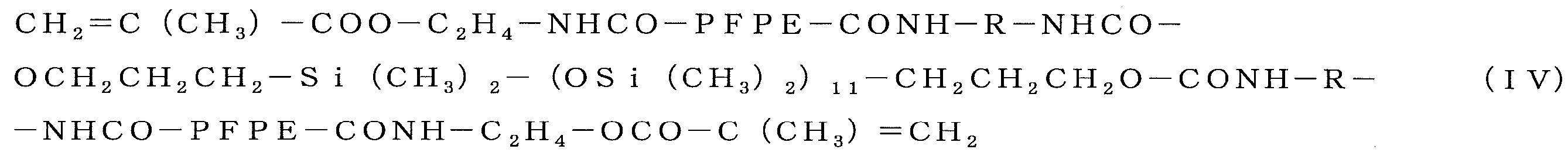
- Example 1 (1) Production of resin In a flask equipped with a stirrer, a nitrogen gas inlet tube, a thermometer and a reflux condenser, 80 parts by weight of methyl methacrylate (trade name: Light Ester M, manufactured by Kyoeisha Chemical Co., Ltd.), Silicone Macromer FM -0711 (molecular weight: 1000) (trade name: Silaplane FM-0711, manufactured by Chisso Corp.) 20 parts by weight and 100 parts by weight of toluene were added.
- methyl methacrylate (trade name: Light Ester M, manufactured by Kyoeisha Chemical Co., Ltd.)
- Silicone Macromer FM -0711 molecular weight: 1000
- Silaplane FM-0711 manufactured by Chisso Corp.
- This silicone macromer FM-0711 is a monofunctional silicone-based macromonomer having a methyl methacrylate group at the end of a molecule piece, and has a structure in which a large number of silicone-based units are bonded by siloxane bonds from the terminal methyl methacrylate group. .
- the resin produced in the above step (1) is diluted 10-fold with toluene to form a PET film (trade name; Lumirror TM , manufactured by Toray Industries, Inc., thickness: 0) 125 mm) and spin-dried at 130 ° C. for 15 minutes using a hot plate to form a resin layer having a thickness of 1.2 ⁇ m. Furthermore, the light transmittance of visible light having a wavelength of 365 nm was measured for this resin-coated PET film (measuring instrument; UV-visible spectrophotometer V-670, manufactured by JASCO Corporation).
- the laminate is cooled to 80 ° C., the master mold is removed, and a resin layer (transfer surface: 576 mm 2 , 150 L / S, period: 300 nm, depth 150 nm) having a pattern formed on one surface is provided.
- a mold was obtained.
- the surface shape was observed using SEM (Hitachi High-Tech Co., Ltd., S-4800), and it was confirmed that there was no defect or shape deformation.
- the contact angle of the obtained nanoimprint resin mold surface with respect to pure water was measured using Kyowa Interface Chemical Co., Ltd., KYOWA CONTACT-ANGLE MATER CA-D type, and it was 110 °.
- the contact angle with respect to pure water was measured in the atmosphere with a minute water droplet of about 1 microliter placed on the sample surface.
- Example 2 In step (1) of Example 1, methyl acrylate; 80 parts by weight, silicone macromer FM-0711 (molecular weight 1000); instead of 20 parts by weight, methyl methacrylate; 99 parts by weight, silicone macromer FM-0711 (molecular weight 1000)
- a resin mold for nanoimprinting was prepared in the same manner as in Example 1 except that the amount was 1 part by weight. Furthermore, 20 shots of continuous light nanoimprinting were performed in the same manner as in Example 1 using the obtained resin mold for nanoimprinting. The obtained resin mold for nanoimprint and the results of nanoimprint are shown in Table 1.
- Example 3 In step (1) of Example 1, methyl acrylate; 80 parts by weight, silicone macromer FM-0711 (molecular weight 1000); instead of 20 parts by weight, methyl methacrylate; 51 parts by weight, silicone macromer FM-0711 (molecular weight 1000)
- a resin mold for nanoimprinting was prepared in the same manner as in Example 1 except that the amount was 49 parts by weight. Furthermore, 20 shots of continuous light nanoimprinting were performed in the same manner as in Example 1 using the obtained resin mold for nanoimprinting. The obtained resin mold for nanoimprint and the results of nanoimprint are shown in Table 1.
- step (1) of Example 1 methyl acrylate; 80 parts by weight, silicone macromer FM-0711 (molecular weight 1000); instead of 20 parts by weight, methyl methacrylate; 99.1 parts by weight, silicone macromer FM-0711 (molecular weight) 1000); a resin mold for nanoimprinting was prepared in the same manner as in Example 1 except that the content was 0.9 parts by weight. The obtained resin mold for nanoimprint and the results of nanoimprint are shown in Table 1.
- step (1) of Example 1 methyl acrylate; 80 parts by weight, silicone macromer FM-0711 (molecular weight 1000); instead of 20 parts by weight, methyl methacrylate; 50 parts by weight, silicone macromer FM-0711 (molecular weight 1000)
- a resin mold for nanoimprinting was prepared in the same manner as in Example 1 except that the amount was 50 parts by weight. However, the resin became cloudy and the light transmittance was lowered, making it impossible to produce a resin mold for optical nanoimprinting. It was. The results are listed in Table 1.
- Example 4 In step (1) of Example 1, silicone macromer FM-0711 (molecular weight 1000); instead of 20 parts by weight, silicone macromer FM-0721 (molecular weight 5000, trade name: Silaplane FM-0721, manufactured by Chisso Corporation) ); A resin mold for nanoimprinting was prepared in the same manner as in Example 1 except that the amount was 20 parts by weight.
- This silicone macromer FM-0721 is a monofunctional silicone-based macromonomer having a methyl methacrylate group at the end of a molecule piece, and has a structure in which a large number of silicone units are bonded via a siloxane bond from the terminal methyl methacrylate group. .
- 20 shots of continuous light nanoimprinting were performed in the same manner as in Example 1 using the obtained resin mold for nanoimprinting.
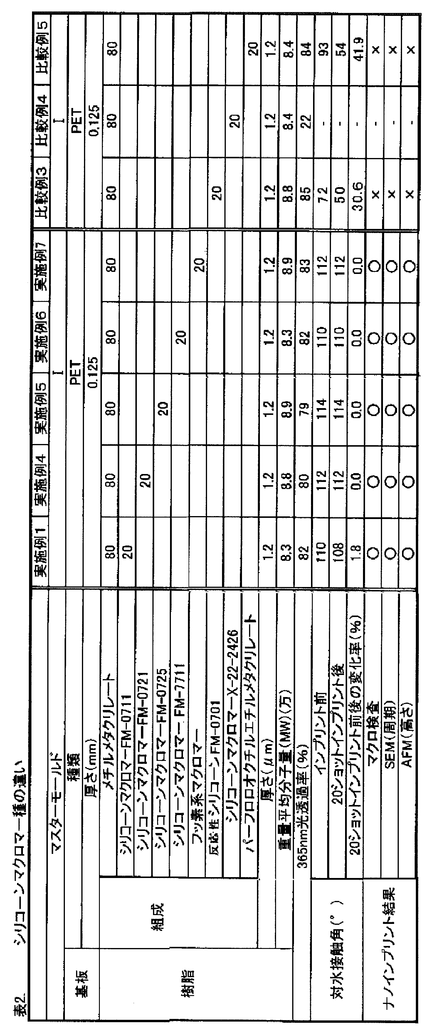
- the obtained resin mold for nanoimprint and the results of nanoimprint are shown in Table 2.
- Example 5 In the step (1) of Example 1, silicone macromer FM-0711 (molecular weight 1000); instead of 20 parts by weight, silicone macromer FM-0725 (molecular weight 10,000, trade name: Silaplane FM-0725, manufactured by Chisso Corporation) ); A resin mold for nanoimprinting was prepared in the same manner as in Example 1 except that the amount was 20 parts by weight.
- This silicone macromer FM-0725 is a monofunctional silicone-based macromonomer having a methyl methacrylate group at the end of a molecular piece, and has a structure in which a large number of silicone-based units are bonded by siloxane bonds from the terminal methyl methacrylate group. .
- 20 shots of continuous light nanoimprinting were performed in the same manner as in Example 1 using the obtained resin mold for nanoimprinting. The obtained resin mold for nanoimprint and the results of nanoimprint are shown in Table 2.
- Example 6 In step (1) of Example 1, silicone macromer FM-0711 (molecular weight 1000); instead of 20 parts by weight, silicone macromer FM-7711 (molecular weight: 1,000, trade name: Silaplane FM-7711, Chisso Corporation) Manufactured); a resin mold for nanoimprinting was prepared in the same manner as in Example 1 except that the amount was 20 parts by weight.
- This silicone macromer FM-7711 is a bifunctional silicone-based macromonomer having methyl methacrylate groups at both ends of the molecule, and has a structure in which a large number of silicone-based units are bonded by siloxane bonds from the terminal methyl methacrylate group. .
- 20 shots of continuous light nanoimprinting were performed in the same manner as in Example 1 using the obtained resin mold for nanoimprinting.
- the obtained resin mold for nanoimprint and the results of nanoimprint are shown in Table 2.
- Example 7 In step (1) of Example 1, instead of silicone macromer FM-0711 (molecular weight 1000); 20 parts by weight, it was prepared by the method described in Example 1 of JP-T-11-503183.
- the molecular mold was 8000; a resin mold for nanoimprinting was prepared in the same manner as in Example 1 except that the amount was 20 parts by weight.
- step (1) of Example 1 instead of 20 parts by weight of silicone macromer FM-0711 (molecular weight 1000); reactive silicone FM-0701 (molecular weight: 423, trade name: Silaplane FM-0701, Chisso Corporation A resin mold for nanoimprinting was prepared in the same manner as in Example 1 except that the amount was 20 parts by weight.
- This reactive silicone FM-0701 is a monofunctional reactive silicone monomer having a methyl methacrylate group at the end of a molecule piece, and has a structure in which a number of silicone units are bonded by a siloxane bond from the terminal methyl methacrylate group. Yes.
- the molecular weight of this FM0701 is 423 and is not a macromonomer.
- Table 2 The obtained resin mold for nanoimprint and the results of nanoimprint are shown in Table 2.
- Example 1 (1) instead of 20 parts by weight of silicone macromer FM-0711 (molecular weight 1000), silicone macromer X-22-2426 20 parts by weight (molecular weight 12,000, trade name: Modified silicone oil X-22-2426 A resin mold for imprinting was produced in the same manner as in Example 1 except that Shin-Etsu Silicone) was used. However, the silicon macromonomer used here has a too high molecular weight and cannot be used as a resin mold for photoimprinting because of the resin cloudiness. The obtained resin mold for imprinting is shown in Table 2.
- step (1) of Example 1 silicone macromer FM-0711 (molecular weight 1000); instead of 20 parts by weight, perfluorooctylethyl methacrylate (molecular weight: 532, trade name; light ester FM-108, Kyoeisha Chemical Co., Ltd.)
- a resin mold for nanoimprinting was prepared in the same manner as in Example 1 except that the amount was 20 parts by weight.
- This perfluorooctylethyl methacrylate has a molecular weight of 532 and is not a macromonomer.
- the obtained resin mold for nanoimprint and the results of nanoimprint are shown in Table 2.
- Example 8 Example 1 except that in the step (1) of Example 1, methyl methacrylate; 80 parts by weight, styrene; 80 parts by weight (trade name: styrene monomer, manufactured by Idemitsu Kosan Co., Ltd.); 80 parts by weight
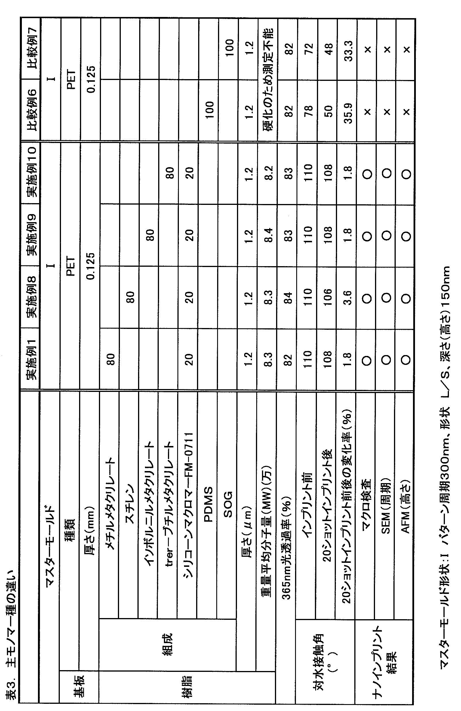
- a resin mold for nanoimprinting was prepared. Furthermore, 20 shots of continuous light nanoimprinting were performed in the same manner as in Example 1 using the obtained resin mold for nanoimprinting. The obtained resin mold for nanoimprinting and the nanoimprinting results are shown in Table 3.
- Example 9 In Step (1) of Example 1, methyl methacrylate; instead of 80 parts by weight, isobornyl methacrylate; 80 parts by weight (trade name: Light Ester IB-X, manufactured by Kyoeisha Chemical Co., Ltd.); 80 parts by weight Except that, a resin mold for nanoimprinting was prepared in the same manner as in Example 1. Furthermore, 20 shots of continuous light nanoimprinting were performed in the same manner as in Example 1 using the obtained resin mold for nanoimprinting. The obtained resin mold for nanoimprinting and the nanoimprinting results are shown in Table 3.
- Example 10 Example 1 except that in the step (1) of Example 1, methyl methacrylate; 80 parts by weight, tert-butyl methacrylate; 80 parts by weight (trade name: Light Ester TB, manufactured by Kyoeisha Chemical Co., Ltd.) was used. In the same manner as in No. 1, a resin mold for nanoimprinting was prepared. Furthermore, 20 shots of continuous light nanoimprinting were performed in the same manner as in Example 1 using the obtained resin mold for nanoimprinting. The obtained resin mold for nanoimprinting and the nanoimprinting results are shown in Table 3.
- the laminate of the film substrate and the resin layer is heated to 40 ° C. using ST-50 manufactured by Toshiba Machine Co., Ltd., and the master mold (exfoliated quartz mold, transfer surface 576 mm 2) is formed on the resin layer surface.
- 150 L / S, period; 300 nm, depth 150 nm) was formed on the resin layer surface.
- the shaped film substrate was cured using a hot plate at 40 ° C. for 12 hours and at 150 ° C. for 30 minutes to form a resin mold for nanoimprinting (transfer surface: 576 mm 2 , 150 L / S, period: 300 nm, depth 150 nm).
- Nanoimprinting was performed in the same manner as in Example 1 (4) using the obtained resin mold for nanoimprinting. Table 3 shows the obtained resin mold for nanoimprint and the results of nanoimprint.
- the shaped film substrate was cured using a hot plate at 40 ° C. for 12 hours and at 150 ° C. for 30 minutes to form a resin mold for nanoimprinting (transfer surface: 576 mm 2 , 150 L / S, period: 300 nm, depth 150 nm).
- Nanoimprinting was performed in the same manner as in Example 1 (4) using the obtained resin mold for nanoimprinting.
- Table 3 shows the obtained resin mold for nanoimprint and the results of nanoimprint.
- Example 11 The resin film thickness in step (2) of Example 1 was changed to 0.4 ⁇ m, and the master mold in step (3) was subjected to a release-treated quartz mold (transfer surface: 576 mm 2 , 25 nmL / S, period: 50 nm, depth) A resin mold for nanoimprinting was prepared in the same manner as in Example 1 except that the thickness was changed to 50 nm). Furthermore, 20-shot continuous light nanoimprinting was performed in the same manner as in Example 1 using the obtained resin mold for nanoimprinting. Table 4 shows the obtained resin mold for nanoimprinting and the results of nanoimprinting.
- Example 12 Except that the master mold in step (3) of Example 1 was changed to a release-treated quartz mold (transfer surface: 576 mm 2 , 75 nmL / S, period: 150 nm, depth: 150 nm), the same as Example 1 A resin mold for nanoimprinting was produced. Furthermore, 20-shot continuous light nanoimprinting was performed in the same manner as in Example 1 using the obtained resin mold for nanoimprinting. Table 4 shows the obtained resin mold for nanoimprinting and the results of nanoimprinting.
- Example 13 Except that the master mold in step (3) of Example 1 was changed to a release-treated quartz mold (transfer surface: 576 mm 2 , 10000 nmL / S, period: 20000 nm, depth: 150 nm), the same as Example 1 A resin mold for nanoimprinting was produced. Furthermore, 20-shot continuous light nanoimprinting was performed in the same manner as in Example 1 using the obtained resin mold for nanoimprinting. Table 4 shows the obtained resin mold for nanoimprinting and the results of nanoimprinting.
- Example 14 Example 1 is the same as Example 1 except that the master mold in the step (3) of Example 1 is changed to a release-treated quartz mold (transfer surface: 576 mm 2 , hole diameter 200 nm, period: 400 nm, depth: 200 nm, cylindrical shape). Similarly, a resin mold for nanoimprinting was produced. Furthermore, 20-shot continuous light nanoimprinting was performed in the same manner as in Example 1 using the obtained resin mold for nanoimprinting. Table 4 shows the obtained resin mold for nanoimprinting and the results of nanoimprinting.
- Example 15 Nanoimprint in the same manner as in Example 1 except that the master mold in step (3) of Example 1 was changed to a release-treated quartz mold (transfer surface: 576 mm 2 , period: 300 nm, depth: 300 nm, moth-eye shape) A resin mold was prepared. Furthermore, 20-shot continuous light nanoimprinting was performed in the same manner as in Example 1 using the obtained resin mold for nanoimprinting. Table 4 shows the obtained resin mold for nanoimprinting and the results of nanoimprinting.
- Example 16 The resin film thickness in the step (2) of Example 1 is 6.4 ⁇ m, and the master mold in the step (3) is a release-treated quartz mold (transfer surface: 576 mm 2 , hole diameter 1000 nm, period 20000 nm, depth: 800 nm, micro A resin mold for nanoimprinting was produced in the same manner as in Example 1 except that the lens shape was changed. Furthermore, 20-shot continuous light nanoimprinting was performed in the same manner as in Example 1 using the obtained resin mold for nanoimprinting. Table 4 shows the obtained resin mold for nanoimprinting and the results of nanoimprinting.
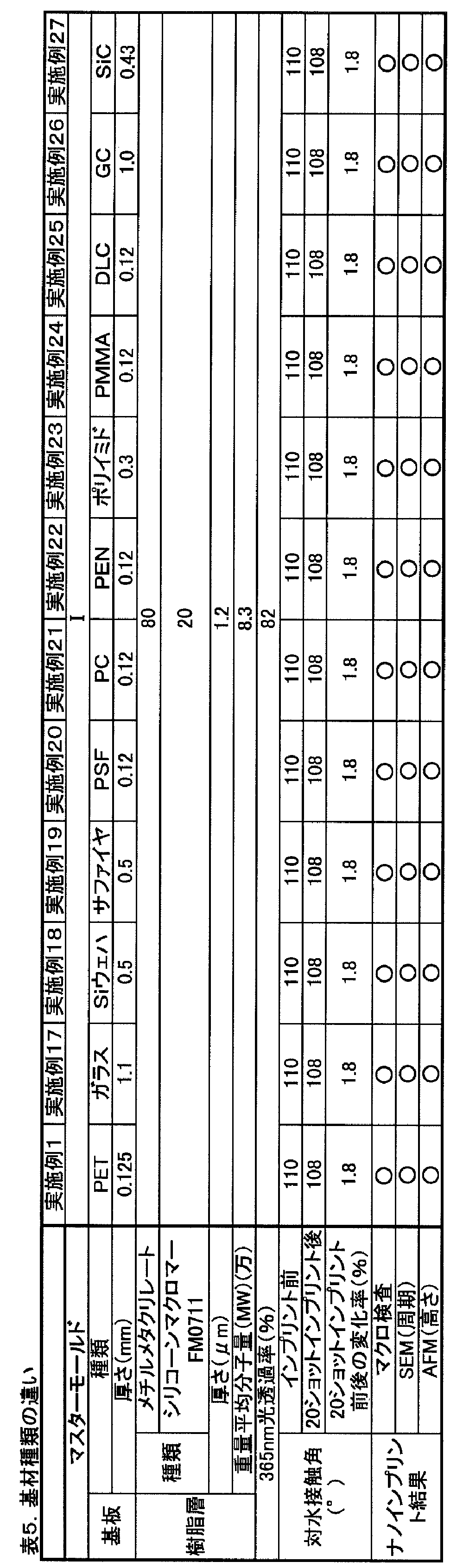
- Example 17 A resin mold for nanoimprinting was prepared in the same manner as in Example 1 except that the PET film as a substrate was changed to soda glass (made by Asahi Glass Co., Ltd., thickness: 1.1 mm) in the step (2) of Example 1. Produced. Using the obtained resin mold for nanoimprinting, 20 shots of continuous light nanoimprinting were performed in the same manner as in Example 1. Table 5 shows the obtained resin mold for nanoimprinting and the nanoimprinting results.
- Example 18 The same procedure as in Example 1 was performed except that the PET film as the substrate was changed to a silicon wafer (Covalent Materials, use grade; polished wafer, thickness: 0.5 mm) in the step (2) of Example 1. Thus, a resin mold for nanoimprinting was produced. Using the obtained resin mold for nanoimprinting, 20 shots of continuous light nanoimprinting were performed in the same manner as in Example 1. Table 5 shows the obtained resin mold for nanoimprinting and the nanoimprinting results.
- Example 19 In the same manner as in Example 1 except that the PET film as the substrate was changed to a sapphire substrate (use grade: semiconductor grade, thickness: 0.5 mm) in the step (2) of Example 1. A resin mold for nanoimprinting was produced. Using the obtained resin mold for nanoimprinting, 20 shots of continuous light nanoimprinting were performed in the same manner as in Example 1. Table 5 shows the obtained resin mold for nanoimprinting and the nanoimprinting results.
- Example 20 Example 1 except that the PET film as a substrate was changed to a PSF film (trade name: Sumilite TM FS-1200, manufactured by Sumitomo Bakelite Co., Ltd., thickness: 0.12 mm) in the step (2) of Example 1.
- a resin mold for nanoimprinting was produced.
- 20 shots of continuous light nanoimprinting were performed in the same manner as in Example 1.
- Table 5 shows the obtained resin mold for nanoimprinting and the nanoimprinting results.
- Example 21 Nanoimprinting in the same manner as in Example 1 except that the PET film as a substrate was changed to a polycarbonate film (trade name: Lexan, manufactured by Asahi Glass Co., Ltd., thickness: 0.12 mm) in the step (2) of Example 1.
- a resin mold was prepared. Using the obtained resin mold for nanoimprinting, 20 shots of continuous light nanoimprinting were performed in the same manner as in Example 1. Table 5 shows the obtained resin mold for nanoimprinting and the nanoimprinting results.
- Example 22 Example except that the PET film as a substrate was changed to a polyethylene naphthalate (PEN) film (trade name: Teonex, manufactured by Teijin Chemicals Ltd., thickness: 0.12 mm) in the step (2) of Example 1.
- PEN polyethylene naphthalate
- a resin mold for nanoimprinting was produced.
- 20 shots of continuous light nanoimprinting were performed in the same manner as in Example 1.
- Table 5 shows the obtained resin mold for nanoimprinting and the nanoimprinting results.
- Example 23 The same procedure as in Example 1 was performed except that the PET film as a substrate was changed to a polyimide film (trade name; Aurum film, manufactured by Mitsui Chemicals, Inc., thickness: 0.3 mm) in the step (2) of Example 1. Thus, a resin mold for nanoimprinting was produced. Using the obtained resin mold for nanoimprinting, 20 shots of continuous light nanoimprinting were performed in the same manner as in Example 1. Table 5 shows the obtained resin mold for nanoimprinting and the nanoimprinting results.
- a polyimide film trade name; Aurum film, manufactured by Mitsui Chemicals, Inc., thickness: 0.3 mm
- Example 24 The same procedure as in Example 1 was performed except that the PET film as a substrate was changed to polymethyl methacrylate (trade name: acrylprene, manufactured by Mitsubishi Rayon Co., Ltd., thickness: 0.12 mm) in the step (2) of Example 1. Thus, a resin mold for nanoimprinting was produced. Using the obtained resin mold for nanoimprinting, 20 shots of continuous light nanoimprinting were performed in the same manner as in Example 1. Table 5 shows the obtained resin mold for nanoimprinting and the nanoimprinting results.
- polymethyl methacrylate trade name: acrylprene, manufactured by Mitsubishi Rayon Co., Ltd., thickness: 0.12 mm
- Example 25 In the step (2) of Example 1, a PET film (film thickness: 1 ⁇ m) was coated with diamond-like carbon (DLC) on the PET film as a substrate (trade name; Genius Coat DLC, Nippon IT F Co., Ltd.) ), Thickness; 0.12 mm).
- DLC diamond-like carbon
- a resin mold for nanoimprinting was produced in the same manner as in Example 1. Using the obtained resin mold for nanoimprinting, 20 shots of continuous light nanoimprinting were performed in the same manner as in Example 1. Table 5 shows the obtained resin mold for nanoimprinting and the nanoimprinting results.
- Example 1 is the same as Example 1 except that the PET film as the substrate was changed to glassy carbon (GC) (use grade: SA-1, manufactured by Tokai Carbon Co., Ltd., thickness: 1 mm) in the step (2) of Example 1. Similarly, a resin mold for nanoimprinting was produced. Using the obtained resin mold for nanoimprinting, 20 shots of continuous light nanoimprinting were performed in the same manner as in Example 1. Table 5 shows the obtained resin mold for nanoimprinting and the nanoimprinting results.
- GC glassy carbon
- Example 27 Same as Example 1 except that the PET film as a substrate was changed to a silicon carbide (SiC) wafer (use grade 6HN-Type, manufactured by TankeBlue, thickness: 0.43 mm) in the step (2) of Example 1. Thus, a resin mold for nanoimprinting was produced. Using the obtained resin mold for nanoimprinting, 20 shots of continuous light nanoimprinting were performed in the same manner as in Example 1. Table 5 shows the obtained resin mold for nanoimprinting and the nanoimprinting results.
- SiC silicon carbide
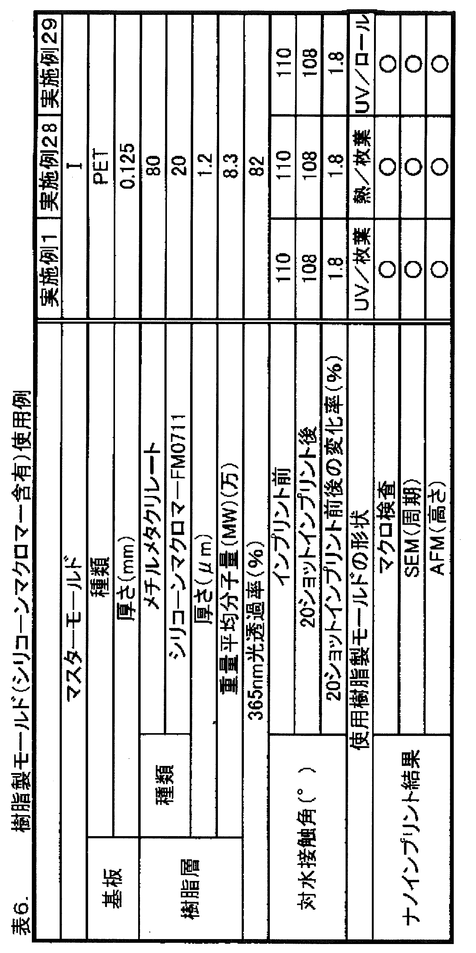
- Example 28 Using the resin mold for nanoimprinting of Example 1, nanoimprinting was performed as follows instead of step (4) of the example.
- a cyclohexyl methacrylate (trade name: Light Ester CH, manufactured by Kyoeisha Chemical Co., Ltd.) polymer prepared in the same step as (1) of Example 1 was spin-coated on a glass substrate in advance, and the resulting resin laminate was heated to 130 ° C.
- a transfer sheet was prepared by heating.
- the resin mold transfer surface 576 mm 2 ⁇ 150 nm L / S ⁇ period 300 nm ⁇ depth 150 nm
- Example 1 was pressed against this transfer sheet and thermally transferred at 80 ° C.
- the press pressure at the time of thermal transfer was 20 MPa, and the holding time was 5 minutes. Thereafter, the laminate was cooled to 65 ° C., the resin mold was removed, and it was confirmed that there were no transfer defects.
- the results are shown in Table 6.
- 20-shot continuous thermal nanoimprinting was performed using this resin mold, imprinting was possible without problems.
- Example 29 Using the resin mold for nanoimprinting of Example 1, nanoimprinting was performed as follows instead of step (4) of Example 1.
- a polycarbonate film (trade name; Lexan film) coated with a photocurable resin PAK-20 (manufactured by Toyo Gosei Co., Ltd.), which is obtained by winding the nanoimprint resin mold obtained in Example 1 around a 6-inch roll. , Thickness: 0.12 mm, manufactured by Asahi Glass Co., Ltd.) at a pressure of 1.0 MPa, the line was moved (feed rate: 1 m / min, the device was made by hand). Thereafter, ultraviolet rays of 70 mW / cm 2 were irradiated while moving the line to cure the resin.
- the resin mold for nanoimprinting was removed from the roll. It was confirmed that there was no missing resin in the mold.
- the resin mold for nanoimprinting was visually checked for the absence of resin after nanoimprinting, and the contact angle was also measured. Further, when the surface state of the nanoimprinted resin was confirmed using SEM and AFM, a pattern having a line width of 150 nm, a period of 300 nm, and a depth of 150 nm was formed. The results are shown in Table 6 as nanoimprint results.
- Resin layer 4 Substrate 5: Resin 6: Substrate 7: Roller type imprint mold 8: Light source
Abstract
Description
該樹脂層は、1~49重量部のシリコーン系マクロモノマーおよび/またはフッ素系マクロモノマーと、99~51重量部の、(メタ)アクリル系モノマー、スチレン系モノマー、エポキシ系モノマー、オレフィン系モノマーおよびポリカーボネート系樹脂形成モノマーよりなる群から選ばれる少なくとも一種類の重合性モノマーとから形成されてなり、
該シリコーン系マクロモノマーおよび/またはフッ素系マクロモノマーの分子量が600~10000の範囲内にあると共に、該マクロモノマーは分子の末端に重合性モノマーと共重合可能な反応性基を有し、該反応性基が上記重合性基と共重合した際に、上記マクロモノマーを構成するシリコーン系ユニットあるいはフッ素系ユニットが重合性モノマーとマクロモノマーとから形成される幹ポリマーに対する側鎖を形成していることを特徴としている。
ただし、上記式(I)において、nは1~15の範囲内の値である。
本発明のモールドは、表面に通常はナノオーダーの微細な凹凸が形成された樹脂層3を有する。この樹脂層3は、基板4の一方の表面に形成されているのが一般的である。
本発明において樹脂層3は、通常は上記のような基板4の表面に形成されている。
本発明において、樹脂層3は、マクロモノマーと、重合性モノマーとの共重合体である。

さらに、オレフィン系モノマーの例としては、エチレン、プロピレン、ヘキセンなどの炭素数2~20の直鎖状オレフィン、環状オレフィンを挙げることができる。
また、エポキシ系モノマーの例としては、グリシジルメタクリレート、4-ヒドロキシブチルアクリレートグリシジルエーテルなどを挙げることができる。
さらにポリカーボネート系樹脂形成モノマーの例としては、ビスフェノールとジフェニルカーボネートあるいはホスゲンとの組み合わせを挙げることができる。
ただし、上記式(I)において、nは通常は1~15の範囲内、好ましくは1~10の範囲内の値である。
このようにロールに本発明のナノインプリント用樹脂製モールドを配置し、光硬化性樹脂を用いることにより、ナノインプリントを連続的に行うことができる。
そして、酸化物層、さらに酸化物の表面に離型剤層を形成することを要しないので、樹脂製モールドを非常に安価に且つ容易に製造することができる。
<重量平均分子量Mw>
ゲルパーミエーションクロマトグラフィー(装置:東ソー株式会社製HLC-8220GPC、溶媒テトラヒドロフラン(THF))により測定し、標準ポリスチレン換算により求められた。
樹脂層の底面と、凹凸パターンを有する表面の中で最も高い面との間を樹脂層の厚さとした。
試料表面に約1μリットルの微少水滴を静置し、協和界面科学社製 KYOWA CONTACT-ANGLE METER CA-D型を用いて、大気中にて測定した。測定条件は、JISR3257に準拠した。
変化率は、(ナノインプリント前剥離剤層接触角―ナノインプリント後剥離剤層接触角)÷ナノインプリント前剥離剤層接触角×100(%)により求めた。
周期及び線幅はSEM(日立ハイテック社製 S―4800)、深さ(高さ)はAFM(SIIナノテクノロジー社製 L-trace)にて評価した。
マクロ評価:光学顕微鏡(ELIPSE LV100 ニコン社製)にてナノインプリントされた樹脂に形成された転写面を×20倍にて観察し、モールドへの樹脂転着の有無を確認した。
○・・・樹脂転着無し
×・・・樹脂転着有り
SEM(周期):ナノインプリントされた樹脂に形成されたパターンをSEMで測定し、ナノインプリント用モールド表面に形成されていたパターンのSEM測定結果を基準とした変化の有無を以下の基準で判断し、評価した。
○・・・変化量が10nm未満
×・・・変化量が10nm以上
AFM(深さ):ナノインプリントされた樹脂に形成されたパターンをAFMで測定し、ナノインプリント用モールド表面に形成されていたパターンのAFM測定結果を基準とした変化の有無を以下の基準で判断し、評価した。
○・・・変化量が10nm未満
×・・・変化量が10nm以上
(1)樹脂の製造
攪拌装置、窒素ガス導入管、温度計および還流冷却管を備えたフラスコに、メチルメタクリレート(商品名:ライトエステルM、共栄社化学(株)製)80重量部、シリコーンマクロマーFM-0711(分子量;1000)(商品名:サイラプレーンFM-0711、チッソ(株)製)20重量部、トルエン100重量部を加えた。このシリコーンマクロマーFM-0711は、分子片末端にメチルメタクリレート基を有する単官能のシリコーン系マクロモノマーであり、末端のメチルメタクリレート基から、シリコーン系ユニットがシロキサン結合で多数結合した構成を有している。
8時間経過後、窒素ガスの導入を止めると共にトルエン100重量部を加えて、内容物の温度を下げることで反応を終了させて、樹脂製モールド用樹脂を得た。
得られた樹脂について、ゲルパーミエーションクロマトグラフィーにより測定した重量平均分子量(MW)は、83,000であった。
上記(1)工程で製造した樹脂を、トルエンを用いて10倍に希釈し、基板となるPETフィルム(商品名;ルミラーTM、東レ(株)製、厚さ;0.125mm)上にスピンコートし、ホットプレートを用いて130℃で15分乾燥させ、膜厚1.2μmの樹脂層を作成した。
さらに、この樹脂塗工済PETフィルムについて、波長365nmの可視光の光透過率を測定した(測定機器;日本分光(株)製、紫外線可視分光光度計V-670)。
上記フィルム基板および樹脂層の積層物を、東芝機械(株)製ST-50を用いて140℃に加熱し、樹脂層表面にマスターモールド(剥離処理済み石英モールド、転写面576mm2、150L/S(Line and Space)、周期;300nm、深さ150nm)を当接し、140℃で熱ナノインプリントを行った。この熱ナノインプリントの際のプレス圧は、20MPa、保持時間は5分間に設定した。
得られたナノインプリント用樹脂製モールドについて、SEM(日立ハイテック(株)製、S-4800)を用いて、表面形状を観察し、欠陥あるいは形状変形がないことを確認した。
また、得られたナノインプリント用樹脂製モールド表面の純水に対する接触角を、協和界面化学(株)製、KYOWA CONTACT-ANGLE MATER CA-D型を用いて測定したところ、110°であった、なお、純水に対する接触角は、試料表面に約1マイクロリットルの微小水滴を静置し、大気中で測定した。
上記のようにして形成したナノインプリント用樹脂製モールドの上に光硬化性樹脂(商品名;PAK-02、東洋合成工業(株)製)を0.2ml滴下し、その上にポリカーボネートフィルム(商品名;レキサン、旭硝子(株)製、厚さ;0.18mm)を静置し、光ナノインプリント装置(エンジニアリング・システム(株)製)を用いて、1.0MPaの圧力で押し付けながら、10mW/cm2の紫外線を2秒間照射した。
上記のような操作を1ショットとして、これを20ショット繰り返した。
その後、ナノインプリント用樹脂製モールドを外した。
また、ナノインプリント済み樹脂について、SEMおよびAFMにより表面形状を確認したところ、線幅;148nm、周期;298nm、深さ148nmのパターンが確認された。
結果を表1にナノインプリント結果として記載する。
実施例1の工程(1)において、メチルアクリレート;80重量部、シリコーンマクロマーFM-0711(分子量1000);20重量部の代わりに、メチルメタクリレート;99重量部、シリコーンマクロマーFM-0711(分子量1000);1重量部とした以外は、実施例1と同様にしてナノインプリント用樹脂製モールドを作成した。
さらに、得られたナノインプリント用樹脂製モールドを用いて実施例1と同様にして20ショットの連続光ナノインプリントを行った。
得られたナノインプリント用樹脂製モールドおよびナノインプリント結果を表1に記載する。
実施例1の工程(1)において、メチルアクリレート;80重量部、シリコーンマクロマーFM-0711(分子量1000);20重量部の代わりに、メチルメタクリレート;51重量部、シリコーンマクロマーFM-0711(分子量1000);49重量部とした以外は、実施例1と同様にしてナノインプリント用樹脂製モールドを作成した。
さらに、得られたナノインプリント用樹脂製モールドを用いて実施例1と同様にして20ショットの連続光ナノインプリントを行った。
得られたナノインプリント用樹脂製モールドおよびナノインプリント結果を表1に記載する。
実施例1の工程(1)において、メチルアクリレート;80重量部、シリコーンマクロマーFM-0711(分子量1000);20重量部の代わりに、メチルメタクリレート;99.1重量部、シリコーンマクロマーFM-0711(分子量1000);0.9重量部とした以外は、実施例1と同様にしてナノインプリント用樹脂製モールドを作成した。
得られたナノインプリント用樹脂製モールドおよびナノインプリント結果を表1に記載する。
実施例1の工程(1)において、メチルアクリレート;80重量部、シリコーンマクロマーFM-0711(分子量1000);20重量部の代わりに、メチルメタクリレート;50重量部、シリコーンマクロマーFM-0711(分子量1000);50重量部とした以外は、実施例1と同様にしてナノインプリント用樹脂製モールドを作成したが、樹脂が白濁して光透過率が下がり、光ナノインプリント用樹脂製モールドを作製することができなかった。
結果を表1に記載する。

実施例1の工程(1)において、シリコーンマクロマーFM-0711(分子量1000);20重量部の代わりに、シリコーンマクロマーFM-0721(分子量5000、商品名;サイラプレーンFM-0721、チッソ(株)製);20重量部とした以外は、実施例1と同様にしてナノインプリント用樹脂製モールドを作成した。このシリコーンマクロマーFM-0721は、分子片末端にメチルメタクリレート基を有する単官能のシリコーン系マクロモノマーであり、末端のメチルメタクリレート基から、シリコーン系ユニットがシロキサン結合で多数結合した構成を有している。
さらに、得られたナノインプリント用樹脂製モールドを用いて実施例1と同様にして20ショットの連続光ナノインプリントを行った。
得られたナノインプリント用樹脂製モールドおよびナノインプリント結果を表2に記載する。
実施例1の工程(1)において、シリコーンマクロマーFM-0711(分子量1000);20重量部の代わりに、シリコーンマクロマーFM-0725(分子量10000、商品名;サイラプレーンFM-0725、チッソ(株)製);20重量部とした以外は、実施例1と同様にしてナノインプリント用樹脂製モールドを作成した。このシリコーンマクロマーFM-0725は、分子片末端にメチルメタクリレート基を有する単官能のシリコーン系マクロモノマーであり、末端のメチルメタクリレート基から、シリコーン系ユニットがシロキサン結合で多数結合した構成を有している。
さらに、得られたナノインプリント用樹脂製モールドを用いて実施例1と同様にして20ショットの連続光ナノインプリントを行った。
得られたナノインプリント用樹脂製モールドおよびナノインプリント結果を表2に記載する。
実施例1の工程(1)において、シリコーンマクロマーFM-0711(分子量1000);20重量部の代わりに、シリコーンマクロマーFM-7711(分子量:1,000、商品名;サイラプレーンFM-7711、チッソ(株)製);20重量部とした以外は、実施例1と同様にしてナノインプリント用樹脂製モールドを作成した。このシリコーンマクロマーFM-7711は、分子の両端にメチルメタクリレート基を有する2官能のシリコーン系マクロモノマーであり、末端のメチルメタクリレート基から、シリコーン系ユニットがシロキサン結合で多数結合した構成を有している。
さらに、得られたナノインプリント用樹脂製モールドを用いて実施例1と同様にして20ショットの連続光ナノインプリントを行った。
得られたナノインプリント用樹脂製モールドおよびナノインプリント結果を表2に記載する。
実施例1の工程(1)において、シリコーンマクロマーFM-0711(分子量1000);20重量部の代わりに、フッ素系マクロマー(特表平11-503183号公報の実施例1に記載の方法で製造したもの、分子量8000);20重量部とした以外は、実施例1と同様にしてナノインプリント用樹脂製モールドを作成した。
得られたナノインプリント用樹脂製モールドおよびナノインプリント結果を表2に記載する。
実施例1の工程(1)において、シリコーンマクロマーFM-0711(分子量1000);20重量部の代わりに、反応性シリコーンFM-0701(分子量:423、商品名;サイラプレーンFM-0701、チッソ(株)製);20重量部とした以外は、実施例1と同様にしてナノインプリント用樹脂製モールドを作成した。この反応性シリコーンFM-0701は、分子片末端にメチルメタクリレート基を有する単官能の反応性シリコーンモノマーであり、末端のメチルメタクリレート基から、シリコーン系ユニットがシロキサン結合で多数結合した構成を有している。このFM0701の分子量は423でありマクロモノマーではない。
得られたナノインプリント用樹脂製モールドおよびナノインプリント結果を表2に記載する。
実施例1の(1)において、シリコーンマクロマーFM-0711(分子量1000) 20重量部の代わりに、シリコーンマクロマー X-22-2426 20重量部(分子量12,000 商品名 変性シリコーンオイル X-22-2426 信越シリコーン社製)を使用した以外は、実施例1と同様にしてインプリント用樹脂製モールドを作製した。しかしながらここで使用したシリコンマクロモノマーは分子量が高すぎて、樹脂白濁のため、光インプリント用樹脂製モールドとして使用することができなかった。得られたインプリント用樹脂製モールドを表2に示す。
実施例1の工程(1)において、シリコーンマクロマーFM-0711(分子量1000);20重量部の代わりに、パーフルオロオクチルエチルメタクリレート(分子量:532、商品名;ライトエステルFM-108、共栄社化学(株)製);20重量部とした以外は、実施例1と同様にしてナノインプリント用樹脂製モールドを作成した。このパーフルオロオクチルエチルメタクリレートは、分子量が532でありマクロモノマーではない。
得られたナノインプリント用樹脂製モールドおよびナノインプリント結果を表2に記載する。
実施例1の工程(1)において、メチルメタクリレート;80重量部の代わりに、スチレン;80重量部(商品名:スチレンモノマー、出光興産(株)製);80重量部とした以外は、実施例1と同様にしてナノインプリント用樹脂製モールドを作成した。
さらに、得られたナノインプリント用樹脂製モールドを用いて実施例1と同様にして20ショットの連続光ナノインプリントを行った。
得られたナノインプリント用樹脂製モールドおよびナノインプリント結果を表3に記載する。
実施例1の工程(1)において、メチルメタクリレート;80重量部の代わりに、イソボルニルメタクリレート;80重量部(商品名:ライトエステルIB-X、共栄社化学(株)製);80重量部とした以外は、実施例1と同様にしてナノインプリント用樹脂製モールドを作成した。
さらに、得られたナノインプリント用樹脂製モールドを用いて実施例1と同様にして20ショットの連続光ナノインプリントを行った。
得られたナノインプリント用樹脂製モールドおよびナノインプリント結果を表3に記載する。
実施例1の工程(1)において、メチルメタクリレート;80重量部の代わりに、tert-ブチルメタクリレート;80重量部(商品名:ライトエステルTB、共栄社化学(株)製)とした以外は、実施例1と同様にしてナノインプリント用樹脂製モールドを作成した。
さらに、得られたナノインプリント用樹脂製モールドを用いて実施例1と同様にして20ショットの連続光ナノインプリントを行った。
得られたナノインプリント用樹脂製モールドおよびナノインプリント結果を表3に記載する。
実施例1の工程(1)~工程(3)の代わりに、以下の操作を行い、ナノインプリント用樹脂製モールドを作成した。
ポリジメチレンシロキサン(PDMS)(商品名;SIM-260,信越シリコーン(株)製);100重量部に、硬化剤(商品名;CAT-260、信越シリコーン(株)製)10重量部を加えてよく攪拌した後、キシレンで10倍に希釈してPETフィルム基板上にスピンコートし、ヒートプレスを用いて、130℃で15分間乾燥させ、膜厚1.3μmの樹脂膜を作製した。このPDMSはシリコーン樹脂硬化体であり、シリコーン系マクロモノマーではない。
次いで、この形状付与済みのフィルム基板をホットプレートを用いて40℃で12時間、150℃で30分間硬化させてナノインプリント用樹脂製モールド(転写面;576mm2、150L/S、周期;300nm、深さ150nm)とした。
得られたナノインプリント用樹脂製モールドを用いて実施例1の(4)と同様にしてナノインプリントを行った。
得られたナノインプリント用樹脂製モールドおよびナノインプリント結果を表3に示す。
スピンオングラス(SOG)(商品名;LHG-NIL-01主剤、LEAP社製);100重量部に、硬化剤(商品名;LHG-NIL-01硬化剤、LEAP社製)10重量部を加えてよく攪拌した後、PETフィルム基板上にスピンコートし、膜厚1.3μmの樹脂膜を作製した。
このスピンオングラスは、スピンコート可能な液状ガラスである。
上記フィルム基板および樹脂層の積層物を、東芝機械(株)製ST-50を用いて40℃に加熱し、樹脂層表面に樹脂層表面にマスターモールド(剥離処理済み石英モールド、転写面576mm2、150L/S、周期;300nm、深さ150nm)を当接し、40℃で熱ナノインプリントを行った。
得られたナノインプリント用樹脂製モールドを用いて実施例1の(4)と同様にしてナノインプリントを行った。
得られたナノインプリント用樹脂製モールドおよびナノインプリント結果を表3に示す。
実施例1の工程(2)の樹脂膜厚を0.4μmに変え、さらに工程(3)におけるマスターモールドを剥離処理済み石英モールド(転写面;576mm2、25nmL/S、周期;50nm、深さ;50nm)に変えた以外は、実施例1と同様にしてナノインプリント用樹脂製モールドを作製した。
さらに得られたナノインプリント用樹脂製モールドを用いて実施例1と同様に20ショットの連続光ナノインプリントを行った。
得られたナノインプリント用樹脂製モールドおよびナノインプリント結果を表4に示す。
実施例1の工程(3)におけるマスターモールドを剥離処理済み石英モールド(転写面;576mm2、75nmL/S、周期;150nm、深さ;150nm)に変えた以外は、実施例1と同様にしてナノインプリント用樹脂製モールドを作製した。
さらに得られたナノインプリント用樹脂製モールドを用いて実施例1と同様に20ショットの連続光ナノインプリントを行った。
得られたナノインプリント用樹脂製モールドおよびナノインプリント結果を表4に示す。
実施例1の工程(3)におけるマスターモールドを剥離処理済み石英モールド(転写面;576mm2、10000nmL/S、周期;20000nm、深さ;150nm)に変えた以外は、実施例1と同様にしてナノインプリント用樹脂製モールドを作製した。
さらに得られたナノインプリント用樹脂製モールドを用いて実施例1と同様に20ショットの連続光ナノインプリントを行った。
得られたナノインプリント用樹脂製モールドおよびナノインプリント結果を表4に示す。
実施例1の工程(3)におけるマスターモールドを剥離処理済み石英モールド(転写面;576mm2、ホール径200nm、周期;400nm、深さ;200nm、円柱形状)に変えた以外は、実施例1と同様にしてナノインプリント用樹脂製モールドを作製した。
さらに得られたナノインプリント用樹脂製モールドを用いて実施例1と同様に20ショットの連続光ナノインプリントを行った。
得られたナノインプリント用樹脂製モールドおよびナノインプリント結果を表4に示す。
実施例1の工程(3)におけるマスターモールドを剥離処理済み石英モールド(転写面;576mm2、周期;300nm、深さ;300nm、モスアイ形状)に変えた以外は、実施例1と同様にしてナノインプリント用樹脂製モールドを作製した。
さらに得られたナノインプリント用樹脂製モールドを用いて実施例1と同様に20ショットの連続光ナノインプリントを行った。
得られたナノインプリント用樹脂製モールドおよびナノインプリント結果を表4に示す。
実施例1の工程(2)の樹脂膜厚を6.4μm、工程(3)におけるマスターモールドを剥離処理済み石英モールド(転写面;576mm2、ホール径1000nm、周期20000nm、深さ;800nm、マイクロレンズ形状)に変えた以外は、実施例1と同様にしてナノインプリント用樹脂製モールドを作製した。
さらに得られたナノインプリント用樹脂製モールドを用いて実施例1と同様に20ショットの連続光ナノインプリントを行った。
得られたナノインプリント用樹脂製モールドおよびナノインプリント結果を表4に示す。

実施例1の工程(2)において、基板であるPETフィルムをソーダガラス(旭硝子(株)製、厚さ;1.1mm)に変更した以外は実施例1と同様にしてナノインプリント用樹脂製モールドを作製した。
得られたナノインプリント用樹脂製モールドを用いて実施例1と同様に20ショットの連続光ナノインプリントを行った。
得られたナノインプリント用樹脂製モールドおよびナノインプリント結果を表5に示す。
実施例1の工程(2)において、基板であるPETフィルムをシリコンウエハ(コバレントマテリアル社製、使用グレード;ポリッシュト・ウェーハ、厚さ;0.5mm)に変更した以外は実施例1と同様にしてナノインプリント用樹脂製モールドを作製した。
得られたナノインプリント用樹脂製モールドを用いて実施例1と同様に20ショットの連続光ナノインプリントを行った。
得られたナノインプリント用樹脂製モールドおよびナノインプリント結果を表5に示す。
実施例1の工程(2)において、基板であるPETフィルムをサファイア基板(オルベパイオニア社製、使用グレード;半導体グレード、厚さ;0.5mm)に変更した以外は実施例1と同様にしてナノインプリント用樹脂製モールドを作製した。
得られたナノインプリント用樹脂製モールドを用いて実施例1と同様に20ショットの連続光ナノインプリントを行った。
得られたナノインプリント用樹脂製モールドおよびナノインプリント結果を表5に示す。
実施例1の工程(2)において、基板であるPETフィルムをPSFフィルム(商品名;スミライトTMFS-1200、住友ベークライト(株)製、厚さ;0.12mm)に変更した以外は実施例1と同様にしてナノインプリント用樹脂製モールドを作製した。
得られたナノインプリント用樹脂製モールドを用いて実施例1と同様に20ショットの連続光ナノインプリントを行った。
得られたナノインプリント用樹脂製モールドおよびナノインプリント結果を表5に示す。
実施例1の工程(2)において、基板であるPETフィルムをポリカーボネートフィルム(商品名;レキサン、旭硝子(株)製、厚さ;0.12mm)に変更した以外は実施例1と同様にしてナノインプリント用樹脂製モールドを作製した。
得られたナノインプリント用樹脂製モールドを用いて実施例1と同様に20ショットの連続光ナノインプリントを行った。
得られたナノインプリント用樹脂製モールドおよびナノインプリント結果を表5に示す。
実施例1の工程(2)において、基板であるPETフィルムをポリエチレンナフタレート(PEN)フィルム(商品名;テオネックス、帝人化成(株)製、厚さ;0.12mm)に変更した以外は実施例1と同様にしてナノインプリント用樹脂製モールドを作製した。
得られたナノインプリント用樹脂製モールドを用いて実施例1と同様に20ショットの連続光ナノインプリントを行った。
得られたナノインプリント用樹脂製モールドおよびナノインプリント結果を表5に示す。
実施例1の工程(2)において、基板であるPETフィルムをポリイミドフィルム(商品名;オーラムフィルム、三井化学(株)製、厚さ;0.3mm)に変更した以外は実施例1と同様にしてナノインプリント用樹脂製モールドを作製した。
得られたナノインプリント用樹脂製モールドを用いて実施例1と同様に20ショットの連続光ナノインプリントを行った。
得られたナノインプリント用樹脂製モールドおよびナノインプリント結果を表5に示す。
実施例1の工程(2)において、基板であるPETフィルムをポリメチルメタクリレート(商品名;アクリプレン、三菱レーヨン(株)製、厚さ;0.12mm)に変更した以外は実施例1と同様にしてナノインプリント用樹脂製モールドを作製した。
得られたナノインプリント用樹脂製モールドを用いて実施例1と同様に20ショットの連続光ナノインプリントを行った。
得られたナノインプリント用樹脂製モールドおよびナノインプリント結果を表5に示す。
実施例1の工程(2)において、基板であるPETフィルムをダイヤモンドライクカーボン(DLC)でコーティング処理(膜厚;1μm)したPETフィルム(商品名;ジニアスコートDLC、日本アイ・ティ・エフ(株)製、厚さ;0.12mm)に変更した以外は実施例1と同様にしてナノインプリント用樹脂製モールドを作製した。
得られたナノインプリント用樹脂製モールドを用いて実施例1と同様に20ショットの連続光ナノインプリントを行った。
得られたナノインプリント用樹脂製モールドおよびナノインプリント結果を表5に示す。
実施例1の工程(2)において、基板であるPETフィルムをグラッシーカーボン(GC)(使用グレード;SA-1、東海カーボン(株)製、厚さ;1mm)に変更した以外は実施例1と同様にしてナノインプリント用樹脂製モールドを作製した。
得られたナノインプリント用樹脂製モールドを用いて実施例1と同様に20ショットの連続光ナノインプリントを行った。
得られたナノインプリント用樹脂製モールドおよびナノインプリント結果を表5に示す。
実施例1の工程(2)において、基板であるPETフィルムを炭化ケイ素(SiC)ウエハ(使用グレード6HN-Type、TankeBlue社製、厚さ;0.43mm)に変更した以外は実施例1と同様にしてナノインプリント用樹脂製モールドを作製した。
得られたナノインプリント用樹脂製モールドを用いて実施例1と同様に20ショットの連続光ナノインプリントを行った。
得られたナノインプリント用樹脂製モールドおよびナノインプリント結果を表5に示す。
実施例1のナノインプリント用樹脂製モールドを用いて、ナノインプリントを実施例の工程(4)の代わりに以下のようにして行った。
実施例1の(1)と同じ工程で作製したシクロヘキシルメタクリレート(商品名ライトエステルCH 共栄社化学(株)製)重合物を予めガラス基板上にスピンコートし、得られた樹脂積層物を130℃に加熱し転写シートを作成した。
この転写シートに実施例1で作製した樹脂製モールド(転写面576mm2・150nmL/S・周期300nm・深さ150nm)を押しつけ80℃で熱転写した。
熱転写時のプレス圧は20MPa、保持時間は5分間であった。
その後、積層物を65℃に冷却し、樹脂製モールドを外し、転写欠陥の無いことを確認した。結果を表6に示す。
また、本樹脂製モールド゛を使用し、20ショットの連続熱ナノインプリントを行ったところ、問題なくインプリントすることができた。
実施例1のナノインプリント用樹脂製モールドを用いて、ナノインプリントを実施例1の工程(4)の代わりに以下のようにして行った。
実施例1で得られたナノインプリント用樹脂製モールドを6インチ径ロールに巻きつけ、光硬化性樹脂PAK-20(東洋合成工業(株)製)が塗布されているポリカーボネートフィルム(商品名;レキサンフィルム、厚さ;0.12mm、旭硝子(株)製)に1.0MPaで押し付けた状態でラインを動かした(送り速度;1m/min、装置は手製)。
その後、ラインを動かしながら70mW/cm2の紫外線を照射し、樹脂を硬化させた。
ナノインプリント用樹脂製モールドのナノインプリント後の樹脂の欠落の有無を目視で確認すると共に接触角についても測定した。
また、ナノインプリント済み樹脂について、SEMおよびAFMを用いて表面状態を確認したところ、線幅;150nm、周期;300nm、深さ;150nmのパターンが形成されていた。
結果を表6中にナノインプリント結果として記載する。
4:基板
5:樹脂
6:基板
7:ローラー式インプリント用モールド
8:光源
Claims (9)
- 基板と、該基板上に形成された樹脂層とからなり、該樹脂層の表面に微細な凹凸が形成されたナノインプリント用樹脂製モールドであって、
該樹脂層は、1~49重量部のシリコーン系マクロモノマーおよび/またはフッ素系マクロモノマーと、99~51重量部の、(メタ)アクリル系モノマー、スチレン系モノマー、エポキシ系モノマー、オレフィン系モノマーおよびポリカーボネート系樹脂形成モノマーよりなる群から選ばれる少なくとも一種類の重合性モノマーとから形成されてなり、
該シリコーン系マクロモノマーおよび/またはフッ素系マクロモノマーの分子量が600~10000の範囲内にあると共に、該マクロモノマーは分子の末端に重合性モノマーと共重合可能な反応性基を有し、該反応性基が上記重合性基と共重合した際に、上記マクロモノマーを構成するシリコーン系ユニットあるいはフッ素系ユニットが重合性モノマーとマクロモノマーとから形成される幹ポリマーに対する側鎖を形成していることを特徴とするナノインプリント用樹脂製モールド。 - 上記樹脂層の厚さをyとし、樹脂層に形成された凸部の高さをxとしたときに、樹脂層は下記式(I)で表わされる関係を有することを特徴とする請求項第1項記載のナノインプリント用樹脂製モールド;
y=n×x ・・・・(I)
(ただし、上記式(I)において、nは1~15の範囲内の値である。)。 - 上記樹脂層の表面に、純水との接触角が100°以上になるようにマクロモノマーの側鎖が存在していることを特徴とする請求項第1項記載のナノインプリント用樹脂製モールド。
- 上記マクロモノマーを構成するシリコーンユニットあるいはフッ素含有ユニットが鎖状構造を形成していることを特徴とする請求項第1項記載のナノインプリント用樹脂製モールド。
- 上記樹脂層を形成する樹脂について、ゲルパーミエーションクロマトグラフィーにより測定された重量平均分子量(MW)が50000~150000の範囲にあることを特徴とする請求項第1項または第2項記載のナノインプリント用樹脂製モールド。
- 上記樹脂層に形成されている表面形状の繰り返し単位が、10~50000nmの範囲内にあることを特徴とする請求項第1項または第2項記載のナノインプリント用樹脂製モールド。
- 上記ナノインプリント用樹脂製モールドにおける365nmの光線透過率が75%以上であることを特徴とする請求項第1項記載のナノインプリント用樹脂製モールド。
- 上記ナノインプリント用樹脂製モールドに配置されている基板が、樹脂基板、ガラス基板、シリコン基板、サファイア基板、炭素基板、および、GaN基板よりなる群から選ばれる一種類の基板であることを特徴とする請求項第1項記載のナノインプリント用樹脂製モールド。
- 上記ナノインプリント用樹脂製モールドが、ローラーの表面に配置されていることを特徴とする請求項第1項記載のナノインプリント用樹脂製モールド。
Priority Applications (7)
| Application Number | Priority Date | Filing Date | Title |
|---|---|---|---|
| KR1020137003986A KR101730577B1 (ko) | 2010-08-06 | 2011-08-03 | 나노 임프린트용 수지제 몰드 |
| DK11814668.7T DK2602088T3 (en) | 2010-08-06 | 2011-08-03 | RESINFORM FOR NANO PREPARATION |
| EP11814668.7A EP2602088B1 (en) | 2010-08-06 | 2011-08-03 | Resin mold for nanoimprinting |
| JP2012527750A JP5292621B2 (ja) | 2010-08-06 | 2011-08-03 | ナノインプリント用樹脂製モールド |
| SG2013008362A SG187701A1 (en) | 2010-08-06 | 2011-08-03 | Resin mold for nanoimprinting |
| CN201180037828.9A CN103052492B (zh) | 2010-08-06 | 2011-08-03 | 纳米压印用树脂制模具 |
| US13/814,298 US9393737B2 (en) | 2010-08-06 | 2011-08-03 | Resin mold for nanoimprinting |
Applications Claiming Priority (2)
| Application Number | Priority Date | Filing Date | Title |
|---|---|---|---|
| JP2010-177600 | 2010-08-06 | ||
| JP2010177600 | 2010-08-06 |
Publications (1)
| Publication Number | Publication Date |
|---|---|
| WO2012018043A1 true WO2012018043A1 (ja) | 2012-02-09 |
Family
ID=45559539
Family Applications (1)
| Application Number | Title | Priority Date | Filing Date |
|---|---|---|---|
| PCT/JP2011/067765 WO2012018043A1 (ja) | 2010-08-06 | 2011-08-03 | ナノインプリント用樹脂製モールド |
Country Status (8)
| Country | Link |
|---|---|
| US (1) | US9393737B2 (ja) |
| EP (1) | EP2602088B1 (ja) |
| JP (1) | JP5292621B2 (ja) |
| KR (1) | KR101730577B1 (ja) |
| CN (1) | CN103052492B (ja) |
| DK (1) | DK2602088T3 (ja) |
| SG (1) | SG187701A1 (ja) |
| WO (1) | WO2012018043A1 (ja) |
Cited By (11)
| Publication number | Priority date | Publication date | Assignee | Title |
|---|---|---|---|---|
| JP2014162016A (ja) * | 2013-02-21 | 2014-09-08 | Toshiba Corp | テンプレート作製方法、テンプレート検査方法、及びテンプレート材料 |
| JP2014228674A (ja) * | 2013-05-22 | 2014-12-08 | セイコーエプソン株式会社 | 回折光学素子、回折光学素子の製造方法、及び電子機器 |
| WO2015012161A1 (ja) * | 2013-07-23 | 2015-01-29 | 旭硝子株式会社 | 第1モールドの凹凸パターンを転写した第2モールド、第2モールドの製造方法、第2モールドを用いた物品の製造方法、光学パネルの製造方法、および光学素子の製造方法 |
| WO2015152310A1 (ja) * | 2014-03-31 | 2015-10-08 | ダイキン工業株式会社 | 成形体およびその製造方法 |
| JP2016094564A (ja) * | 2014-11-17 | 2016-05-26 | 株式会社トクヤマ | インプリント用光硬化性組成物、及び該組成物を用いたレジスト積層体の製造方法 |
| JPWO2016051928A1 (ja) * | 2014-10-04 | 2017-09-28 | 富山県 | インプリント用テンプレート及びその製造方法 |
| JP2018178087A (ja) * | 2017-04-14 | 2018-11-15 | 三星ディスプレイ株式會社Samsung Display Co.,Ltd. | ソフトモールド用組成物、これを利用して製造されたソフトモールド |
| KR20190005821A (ko) | 2016-05-11 | 2019-01-16 | 디아이씨 가부시끼가이샤 | 광 임프린트용 경화성 조성물 및 그것을 사용한 패턴 전사 방법 |
| WO2021009980A1 (ja) | 2019-07-12 | 2021-01-21 | 三井化学株式会社 | 光硬化性組成物、凹凸構造体の製造方法、微細凹凸パターンを形成する方法および凹凸構造体 |
| US11414508B2 (en) | 2017-03-29 | 2022-08-16 | Mitsubishi Chemical Corporation | Resin composition with a (meth)acrylic copolymer, antifouling paint composition, and method for producing same |
| US11643489B2 (en) | 2015-09-25 | 2023-05-09 | Mitsubishi Chemical Corporation | (Meth)acrylic copolymer, polymer solution, polymer-containing composition, anti-fouling coating composition, and method for producing (meth)acrylic copolymer |
Families Citing this family (9)
| Publication number | Priority date | Publication date | Assignee | Title |
|---|---|---|---|---|
| WO2007081876A2 (en) * | 2006-01-04 | 2007-07-19 | Liquidia Technologies, Inc. | Nanostructured surfaces for biomedical/biomaterial applications and processes thereof |
| US20170361523A1 (en) | 2014-12-10 | 2017-12-21 | Inmold A/S | Method and apparatus for producing a nanostructured or microstructured foil by extrusion coating or extrusion casting |
| WO2016145115A1 (en) | 2015-03-09 | 2016-09-15 | Sportsmedia Technology Corporation | Determining and synchronizing live event information |
| US10943435B2 (en) | 2015-03-09 | 2021-03-09 | Sportsmedia Technology Corporation | Systems and methods for providing secure data for wagering for live sports events |
| WO2017156054A1 (en) | 2016-03-09 | 2017-09-14 | Sportsmedia Technology Corporation | Systems and methods for providing secure data for wagering for live sporting events |
| KR20180014287A (ko) | 2016-07-28 | 2018-02-08 | 삼성디스플레이 주식회사 | 패터닝된 경화물의 제조 방법 및 패터닝된 경화물 |
| IL267443B2 (en) * | 2016-12-22 | 2023-10-01 | Illumina Inc | stamping device |
| KR102101344B1 (ko) | 2018-04-16 | 2020-04-16 | 한국화학연구원 | 롤투롤 나노 임프린트 복제 몰드 제작용 광중합성 조성물 및 이를 포함하는 복제 몰드 |
| CN112571687A (zh) * | 2020-12-28 | 2021-03-30 | 上海建工四建集团有限公司 | 一种高开孔率复合硅胶模具 |
Citations (10)
| Publication number | Priority date | Publication date | Assignee | Title |
|---|---|---|---|---|
| JPS58167606A (ja) | 1982-03-27 | 1983-10-03 | Toagosei Chem Ind Co Ltd | ラジカル共重合によるグラフト共重合体の製造方法 |
| JPS5978236A (ja) | 1982-10-28 | 1984-05-07 | Toagosei Chem Ind Co Ltd | ビニル重合反応性直鎖シリコ−ン高分子量モノマ−の製造法 |
| JPS60123518A (ja) | 1983-12-09 | 1985-07-02 | Toagosei Chem Ind Co Ltd | シリコ−ン系グラフト共重合体の製造方法 |
| JPH04353407A (ja) * | 1991-05-30 | 1992-12-08 | Olympus Optical Co Ltd | プラスチック成形型 |
| JPH11503183A (ja) | 1995-04-04 | 1999-03-23 | ノバルティス アクチエンゲゼルシャフト | 重合性ペルフルオロアルキルエーテルシロキサンマクロマー |
| JP2006182011A (ja) | 2004-11-30 | 2006-07-13 | Asahi Glass Co Ltd | 光硬化性樹脂成型用モールドおよび該モールドを用いる硬化物の製造方法 |
| JP2006198883A (ja) | 2005-01-20 | 2006-08-03 | Asahi Glass Co Ltd | モールドおよび表面に微細パターンを有する物品 |
| WO2008096594A1 (ja) * | 2007-02-07 | 2008-08-14 | Asahi Glass Company, Limited | インプリント用モールドおよびその製造方法 |
| JP2009019174A (ja) | 2007-07-13 | 2009-01-29 | Asahi Kasei Corp | 光硬化性樹脂組成物及び、成型体及び、成型体の製造方法 |
| JP2010000612A (ja) | 2008-06-18 | 2010-01-07 | Fujifilm Corp | ナノインプリント用硬化性組成物、パターン形成方法 |
Family Cites Families (12)
| Publication number | Priority date | Publication date | Assignee | Title |
|---|---|---|---|---|
| US5330882A (en) * | 1990-06-05 | 1994-07-19 | Nippon Paint Co., Ltd. | Process for exposing a photosensitive resin composition to light |
| JP3144290B2 (ja) * | 1995-12-15 | 2001-03-12 | 三菱エンジニアリングプラスチックス株式会社 | 熱可塑性樹脂とオイルブリード性シリコーンゴムとの一体成形体 |
| TW574276B (en) * | 2001-05-09 | 2004-02-01 | Mitsubishi Plastics Inc | Porous film and its production process |
| US7420005B2 (en) * | 2001-06-28 | 2008-09-02 | Dai Nippon Printing Co., Ltd. | Photocurable resin composition, finely embossed pattern-forming sheet, finely embossed transfer sheet, optical article, stamper and method of forming finely embossed pattern |
| DE602004015588D1 (de) * | 2003-04-25 | 2008-09-18 | Kaneka Corp | Reaktives modifizierungsmittel |
| JP4655043B2 (ja) | 2004-11-30 | 2011-03-23 | 旭硝子株式会社 | モールド、および転写微細パターンを有する基材の製造方法 |
| US7478791B2 (en) * | 2005-04-15 | 2009-01-20 | 3M Innovative Properties Company | Flexible mold comprising cured polymerizable resin composition |
| JPWO2008015842A1 (ja) * | 2006-08-03 | 2009-12-17 | 旭硝子株式会社 | モールドの製造方法 |
| US8027086B2 (en) | 2007-04-10 | 2011-09-27 | The Regents Of The University Of Michigan | Roll to roll nanoimprint lithography |
| JP5101343B2 (ja) * | 2008-03-03 | 2012-12-19 | 株式会社ダイセル | 微細構造物の製造方法 |
| JP5007827B2 (ja) * | 2008-04-04 | 2012-08-22 | 信越化学工業株式会社 | ダブルパターン形成方法 |
| JP5611519B2 (ja) | 2008-10-29 | 2014-10-22 | 富士フイルム株式会社 | ナノインプリント用組成物、パターンおよびその形成方法 |
-
2011
- 2011-08-03 EP EP11814668.7A patent/EP2602088B1/en not_active Not-in-force
- 2011-08-03 JP JP2012527750A patent/JP5292621B2/ja not_active Expired - Fee Related
- 2011-08-03 KR KR1020137003986A patent/KR101730577B1/ko active IP Right Grant
- 2011-08-03 CN CN201180037828.9A patent/CN103052492B/zh not_active Expired - Fee Related
- 2011-08-03 DK DK11814668.7T patent/DK2602088T3/en active
- 2011-08-03 SG SG2013008362A patent/SG187701A1/en unknown
- 2011-08-03 WO PCT/JP2011/067765 patent/WO2012018043A1/ja active Application Filing
- 2011-08-03 US US13/814,298 patent/US9393737B2/en active Active
Patent Citations (10)
| Publication number | Priority date | Publication date | Assignee | Title |
|---|---|---|---|---|
| JPS58167606A (ja) | 1982-03-27 | 1983-10-03 | Toagosei Chem Ind Co Ltd | ラジカル共重合によるグラフト共重合体の製造方法 |
| JPS5978236A (ja) | 1982-10-28 | 1984-05-07 | Toagosei Chem Ind Co Ltd | ビニル重合反応性直鎖シリコ−ン高分子量モノマ−の製造法 |
| JPS60123518A (ja) | 1983-12-09 | 1985-07-02 | Toagosei Chem Ind Co Ltd | シリコ−ン系グラフト共重合体の製造方法 |
| JPH04353407A (ja) * | 1991-05-30 | 1992-12-08 | Olympus Optical Co Ltd | プラスチック成形型 |
| JPH11503183A (ja) | 1995-04-04 | 1999-03-23 | ノバルティス アクチエンゲゼルシャフト | 重合性ペルフルオロアルキルエーテルシロキサンマクロマー |
| JP2006182011A (ja) | 2004-11-30 | 2006-07-13 | Asahi Glass Co Ltd | 光硬化性樹脂成型用モールドおよび該モールドを用いる硬化物の製造方法 |
| JP2006198883A (ja) | 2005-01-20 | 2006-08-03 | Asahi Glass Co Ltd | モールドおよび表面に微細パターンを有する物品 |
| WO2008096594A1 (ja) * | 2007-02-07 | 2008-08-14 | Asahi Glass Company, Limited | インプリント用モールドおよびその製造方法 |
| JP2009019174A (ja) | 2007-07-13 | 2009-01-29 | Asahi Kasei Corp | 光硬化性樹脂組成物及び、成型体及び、成型体の製造方法 |
| JP2010000612A (ja) | 2008-06-18 | 2010-01-07 | Fujifilm Corp | ナノインプリント用硬化性組成物、パターン形成方法 |
Cited By (18)
| Publication number | Priority date | Publication date | Assignee | Title |
|---|---|---|---|---|
| JP2014162016A (ja) * | 2013-02-21 | 2014-09-08 | Toshiba Corp | テンプレート作製方法、テンプレート検査方法、及びテンプレート材料 |
| JP2014228674A (ja) * | 2013-05-22 | 2014-12-08 | セイコーエプソン株式会社 | 回折光学素子、回折光学素子の製造方法、及び電子機器 |
| WO2015012161A1 (ja) * | 2013-07-23 | 2015-01-29 | 旭硝子株式会社 | 第1モールドの凹凸パターンを転写した第2モールド、第2モールドの製造方法、第2モールドを用いた物品の製造方法、光学パネルの製造方法、および光学素子の製造方法 |
| WO2015152310A1 (ja) * | 2014-03-31 | 2015-10-08 | ダイキン工業株式会社 | 成形体およびその製造方法 |
| JPWO2015152310A1 (ja) * | 2014-03-31 | 2017-04-13 | ダイキン工業株式会社 | 成形体およびその製造方法 |
| JPWO2016051928A1 (ja) * | 2014-10-04 | 2017-09-28 | 富山県 | インプリント用テンプレート及びその製造方法 |
| JP2016094564A (ja) * | 2014-11-17 | 2016-05-26 | 株式会社トクヤマ | インプリント用光硬化性組成物、及び該組成物を用いたレジスト積層体の製造方法 |
| US11643489B2 (en) | 2015-09-25 | 2023-05-09 | Mitsubishi Chemical Corporation | (Meth)acrylic copolymer, polymer solution, polymer-containing composition, anti-fouling coating composition, and method for producing (meth)acrylic copolymer |
| KR20190005821A (ko) | 2016-05-11 | 2019-01-16 | 디아이씨 가부시끼가이샤 | 광 임프린트용 경화성 조성물 및 그것을 사용한 패턴 전사 방법 |
| US11226553B2 (en) | 2016-05-11 | 2022-01-18 | Dic Corporation | Photo-imprinting curable composition and pattern transferring method using the same |
| US11414508B2 (en) | 2017-03-29 | 2022-08-16 | Mitsubishi Chemical Corporation | Resin composition with a (meth)acrylic copolymer, antifouling paint composition, and method for producing same |
| JP7112219B2 (ja) | 2017-04-14 | 2022-08-03 | 三星ディスプレイ株式會社 | ソフトモールド用組成物、これを利用して製造されたソフトモールド |
| JP2018178087A (ja) * | 2017-04-14 | 2018-11-15 | 三星ディスプレイ株式會社Samsung Display Co.,Ltd. | ソフトモールド用組成物、これを利用して製造されたソフトモールド |
| WO2021009980A1 (ja) | 2019-07-12 | 2021-01-21 | 三井化学株式会社 | 光硬化性組成物、凹凸構造体の製造方法、微細凹凸パターンを形成する方法および凹凸構造体 |
| KR20210121127A (ko) | 2019-07-12 | 2021-10-07 | 미쓰이 가가쿠 가부시키가이샤 | 광경화성 조성물, 요철 구조체의 제조 방법, 미세 요철 패턴을 형성하는 방법 및 요철 구조체 |
| JPWO2021009980A1 (ja) * | 2019-07-12 | 2021-11-25 | 三井化学株式会社 | 光硬化性組成物、凹凸構造体の製造方法、微細凹凸パターンを形成する方法および凹凸構造体 |
| JP7284820B2 (ja) | 2019-07-12 | 2023-05-31 | 三井化学株式会社 | 光硬化性組成物、凹凸構造体の製造方法、微細凹凸パターンを形成する方法および凹凸構造体 |
| US11958971B2 (en) | 2019-07-12 | 2024-04-16 | Mitsui Chemicals, Inc. | Photocurable composition, method for producing concave-convex structure, method for forming fine concave-convex pattern, and concave-convex structure |
Also Published As
| Publication number | Publication date |
|---|---|
| EP2602088A1 (en) | 2013-06-12 |
| KR101730577B1 (ko) | 2017-04-26 |
| SG187701A1 (en) | 2013-03-28 |
| JP5292621B2 (ja) | 2013-09-18 |
| DK2602088T3 (en) | 2018-05-07 |
| JPWO2012018043A1 (ja) | 2013-10-03 |
| EP2602088A4 (en) | 2015-10-07 |
| CN103052492B (zh) | 2014-12-31 |
| CN103052492A (zh) | 2013-04-17 |
| US20130136818A1 (en) | 2013-05-30 |
| EP2602088B1 (en) | 2018-03-21 |
| KR20130096242A (ko) | 2013-08-29 |
| US9393737B2 (en) | 2016-07-19 |
Similar Documents
| Publication | Publication Date | Title |
|---|---|---|
| JP5292621B2 (ja) | ナノインプリント用樹脂製モールド | |
| US11079683B2 (en) | Aperture system for preceramic polymer stereolithography | |
| JP5908214B2 (ja) | 樹脂モールド及びその製造方法 | |
| JP4901467B2 (ja) | 有機モールド及びその製造方法 | |
| JP5594147B2 (ja) | 光硬化性組成物および表面に微細パターンを有する成形体の製造方法 | |
| KR101652680B1 (ko) | 광경화성 조성물 및 표면에 미세 패턴을 갖는 성형체의 제조 방법 | |
| JPWO2006059580A1 (ja) | モールド、および転写微細パターンを有する基材の製造方法 | |
| JP2009001002A (ja) | モールド、その製造方法および転写微細パターンを有する基材の製造方法 | |
| JP2006182011A (ja) | 光硬化性樹脂成型用モールドおよび該モールドを用いる硬化物の製造方法 | |
| JP2007245702A (ja) | テンプレートおよび転写微細パターンを有する処理基材の製造方法 | |
| JP6332717B2 (ja) | 光インプリント用硬化性組成物及びそれを用いたパターン転写方法 | |
| JP2007320072A (ja) | モールドおよびその製造方法 | |
| JP5208646B2 (ja) | 成形体、並びに成形体の製造方法、及び成形体を転写した転写体の製造方法 | |
| JP2006137021A (ja) | 転写体の製造方法 | |
| JP4418880B2 (ja) | 表面にミクロな構造を有する微細構造体 | |
| JP2006150741A (ja) | 転写層にパターンを形成する方法 | |
| JP2012116108A (ja) | 樹脂モールド |
Legal Events
| Date | Code | Title | Description |
|---|---|---|---|
| WWE | Wipo information: entry into national phase |
Ref document number: 201180037828.9 Country of ref document: CN |
|
| 121 | Ep: the epo has been informed by wipo that ep was designated in this application |
Ref document number: 11814668 Country of ref document: EP Kind code of ref document: A1 |
|
| WWE | Wipo information: entry into national phase |
Ref document number: 2012527750 Country of ref document: JP |
|
| WWE | Wipo information: entry into national phase |
Ref document number: 13814298 Country of ref document: US |
|
| NENP | Non-entry into the national phase |
Ref country code: DE |
|
| WWE | Wipo information: entry into national phase |
Ref document number: 2011814668 Country of ref document: EP |
|
| ENP | Entry into the national phase |
Ref document number: 20137003986 Country of ref document: KR Kind code of ref document: A |