WO2012018028A1 - 電池劣化検知装置および電池劣化検知方法ならびにそのプログラム - Google Patents
電池劣化検知装置および電池劣化検知方法ならびにそのプログラム Download PDFInfo
- Publication number
- WO2012018028A1 WO2012018028A1 PCT/JP2011/067709 JP2011067709W WO2012018028A1 WO 2012018028 A1 WO2012018028 A1 WO 2012018028A1 JP 2011067709 W JP2011067709 W JP 2011067709W WO 2012018028 A1 WO2012018028 A1 WO 2012018028A1
- Authority
- WO
- WIPO (PCT)
- Prior art keywords
- value
- storage battery
- internal resistance
- battery
- current
- Prior art date
- Legal status (The legal status is an assumption and is not a legal conclusion. Google has not performed a legal analysis and makes no representation as to the accuracy of the status listed.)
- Ceased
Links
Images


Classifications
-
- G—PHYSICS
- G01—MEASURING; TESTING
- G01R—MEASURING ELECTRIC VARIABLES; MEASURING MAGNETIC VARIABLES
- G01R31/00—Arrangements for testing electric properties; Arrangements for locating electric faults; Arrangements for electrical testing characterised by what is being tested not provided for elsewhere
- G01R31/36—Arrangements for testing, measuring or monitoring the electrical condition of accumulators or electric batteries, e.g. capacity or state of charge [SoC]
- G01R31/392—Determining battery ageing or deterioration, e.g. state of health
-
- G—PHYSICS
- G01—MEASURING; TESTING
- G01R—MEASURING ELECTRIC VARIABLES; MEASURING MAGNETIC VARIABLES
- G01R31/00—Arrangements for testing electric properties; Arrangements for locating electric faults; Arrangements for electrical testing characterised by what is being tested not provided for elsewhere
- G01R31/36—Arrangements for testing, measuring or monitoring the electrical condition of accumulators or electric batteries, e.g. capacity or state of charge [SoC]
- G01R31/389—Measuring internal impedance, internal conductance or related variables
Definitions
- the present invention relates to a battery deterioration detection device, a battery deterioration detection method, and a program for detecting deterioration of a storage battery.
- Patent Document 1 is disclosed as a technique for detecting battery deterioration.
- the technique of the above-mentioned patent document 1 shifts to a constant voltage charge that continuously maintains the voltage after the lithium ion secondary battery is charged with constant current and the voltage reaches a specified voltage value. Then, the current behavior is measured from the current flowing through the battery when the charging method is switched to constant voltage charging and the current flowing through the battery after a predetermined time has elapsed, and the degree of deterioration of the battery is estimated.
- Patent Document 1 when the load pattern of the storage battery cannot be assumed, it is understood when a situation occurs in which constant current charging is performed and switching to constant voltage charging can be performed after the voltage reaches a specified voltage value. Therefore, there is a problem that deterioration of the storage battery cannot be detected at a desired time. Moreover, when estimating a deterioration degree from an electric current or a voltage in the environment where the temperature of a storage battery changes, it is necessary to exclude the influence which temperature has on a battery characteristic.
- an object of the present invention is to provide a battery deterioration detection device, a battery deterioration detection method, and a program thereof that can solve the above-described problems.
- the present invention obtains a current value input to and output from a storage battery and a voltage value applied to the storage battery, and a fluctuation range of the current value when the current value fluctuates by a certain value or more.
- An internal resistance value calculation unit that calculates the current internal resistance value of the storage battery using the fluctuation range of the voltage value at that time, and an internal value corresponding to the current temperature of the storage battery
- a battery deterioration information processing unit comprising: a battery deterioration information processing unit that calculates a deterioration rate of the storage battery at a current temperature of the storage battery by dividing by a resistance initial value and outputs the deterioration rate to a monitor device; Device.
- the internal resistance value calculation unit may determine that the fluctuation of the current flowing into and out of the storage battery is not more than a specified value for a predetermined period before the current value fluctuates more than a certain value. When the state continues, the current internal resistance value is calculated.
- the battery deterioration detection device further includes an internal resistance initial value storage unit that stores an internal resistance initial value at each of different temperatures of the storage battery, and the internal resistance value calculation unit acquires the acquired The internal resistance initial value corresponding to the temperature of the storage battery is calculated based on the internal resistance initial value at each of different temperatures recorded in the internal resistance initial value storage unit.
- the battery deterioration information processing unit calculates an average of a plurality of calculated deterioration rates, and outputs the average value of the deterioration rates to the monitor device.
- the above-described battery deterioration detection device has the square root rule indicating the relationship between the operation days of the storage battery and the deterioration rate, and the internal resistance value of the storage battery in a state where the storage battery should be determined to have a life.
- the deterioration rate calculating the life determination days that the storage battery is determined to have a life, subtracting the current operation days from the life determination days, and calculating the remaining life days calculation unit for calculating the remaining life days of the storage battery; It is characterized by providing.
- the present invention provides a battery deterioration detection method for a battery deterioration detection device, wherein a current value input / output to / from a storage battery and a voltage value applied to the storage battery are acquired, and the current value when the current value fluctuates by a certain value or more.
- the current internal resistance value of the storage battery is calculated using the fluctuation range of the current value and the fluctuation range of the voltage value at that time, and the current internal resistance value is an internal value corresponding to the current temperature of the storage battery.
- the deterioration rate of the storage battery at the current temperature of the storage battery is calculated, and the deterioration rate is output to the monitor device.
- the present invention also provides a computer of a battery deterioration detection device for acquiring a current value inputted to and outputted from a storage battery and a voltage value applied to the storage battery, and a fluctuation range of the current value when the current value fluctuates more than a predetermined value. And an internal resistance value calculation process for calculating the current internal resistance value of the storage battery using the fluctuation range of the voltage value at that time, the internal current value corresponding to the current temperature of the storage battery
- the program is characterized in that it is divided by the initial resistance value to calculate a deterioration rate of the storage battery at the current temperature of the storage battery, and functions as battery deterioration information processing for outputting the deterioration rate to the monitor device.
- the current parameter value, voltage parameter value, and temperature parameter value of the storage battery are intermittently obtained, and the internal resistance value at that time is calculated using the parameter values, and the deterioration rate of the storage battery is calculated. At the same time, it is determined whether the deterioration rate is equal to or higher than the limit deterioration rate using the accurate deterioration rate. Therefore, the deterioration state of the battery can be detected regardless of the load pattern of the storage battery.
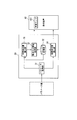
- FIG. 1 is a block diagram showing the configuration of the battery deterioration detection device according to the embodiment.
- the battery deterioration detection device 1 is a new transportation system such as an RTG (Rubber Tired Gantry crane), APM (Automated People Mover), or LRT (Light Rail Transit) that operates based on electric power stored in a storage battery.
- the vehicle is equipped.
- the battery deterioration detection device 1 includes a storage battery 10, a BMS (Battery Management System) 20, a controller (Programmable Logic Controller) 30, a display device 40, and a power load 50.
- BMS Battery Management System
- controller Programmable Logic Controller
- the battery deterioration detection apparatus 1 of the present invention is an airplane in which a propeller or a screw is connected to an electric motor that is an electric vehicle or an industrial vehicle such as an electric vehicle or a forklift, or an electric vehicle, in addition to RTG, APM, and LRT. Alternatively, it may be provided in a moving body such as a ship. Furthermore, the battery deterioration detection device 1 is provided in a stationary system such as a household power storage system or a grid-connected smoothing power storage system combined with a natural energy power generation such as a windmill or sunlight. It may be.
- the storage battery 10 supplies power to the power load 50 of the electric system provided with the battery deterioration detection device 1, and is constituted by the secondary battery 11 in this embodiment.
- the storage battery 10 may be configured by connecting a plurality of secondary batteries 11 in series.
- the storage battery 10 may be a plurality of secondary batteries 11 connected in parallel.
- Various sensors for measuring temperature, voltage, current, etc. are attached to the secondary battery 11 constituting the storage battery 10, and the measurement information measured and output by these sensors is input to the BMS 20 described in detail later. Is done.
- the storage battery 10 is comprised by the several secondary battery 11, the said various sensors are attached to each.
- the controller 30 receives the measurement information of the storage battery 10 transmitted from the BMS 20 and displays the related information (such as the deterioration rate of the storage battery and the remaining life days) calculated based on the measurement information on the display device 40. It controls and makes it display on the said display apparatus 40 suitably. Further, when the controller 30 determines that the related information is an abnormal value, the controller 30 turns on an abnormal lamp 401 built in the display device 40 or the like. In addition, an alarm may be displayed by operating a sound device such as a buzzer built in the display device 40, and a visual and auditory sense is stimulated by light and sound. May be prompted.
- a sound device such as a buzzer built in the display device 40
- the display device 40 is a monitor such as a liquid crystal panel including the acoustic device, for example, and displays the related information of the secondary battery 11 constituting the storage battery 10 based on the control from the controller 30.
- the power load 50 is a power converter such as an electric motor or an inverter connected to a vehicle wheel, for example.
- the power load 50 may be an electric motor that drives a wiper or the like.
- the BMS 20 of the battery deterioration detection device 1 includes a CMU (Cell Monitor Unit) 21 and a BMU (Battery Management Unit) 23.
- the CMU 21 includes an ADC (Analog Digital Converter) (not shown), receives a plurality of the measurement information detected and output by the various sensors as analog signals, and the analog signals correspond to the ADCs, respectively. After being converted into a digital signal, it is output to the BMU 23 as a plurality of parameters for calculating the related information.
- CMU21 is connected with the secondary battery 11 by the signal wire
- the BMU 23 outputs the parameters of the storage battery 10 input from the CMU 21 to the controller 30.
- the storage battery 10 includes a plurality of secondary batteries 11, a plurality of CMUs 21 may be provided, and a plurality of secondary batteries 11 may be connected to each CMU 21.
- the CMU 21 may be provided in a one-to-one relationship. That is, as long as the BMU 23 can acquire a plurality of parameters necessary for performing the deterioration rate calculation process and the remaining life days calculation process from the CMU 21, the number of the CMUs 21 may be any number. If the BMU 23 is configured including the CMU 21, the BMS 20 may be configured only by the BMU 23.
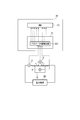
- FIG. 2 is a schematic configuration diagram of a BMS and a storage battery.
- a voltmeter 3 is provided for the secondary battery 11 constituting the storage battery 10.
- the voltmeter 3 is connected between the positive electrode terminal and the negative electrode terminal of the secondary battery 11.
- the CMU 21 includes a parameter value detection unit 211.
- the parameter value detection unit 211 acquires a voltage value as measurement information measured and output by the voltmeter 3 as an analog signal (the analog signal is a parameter value detection unit). 211).
- the ammeter 2 is connected between the storage battery 10 and the power load 50 in order to measure the current flowing through the power load 50.
- the parameter value detection unit 211 acquires a current value as measurement information measured and output by the ammeter 2 as an analog signal (the analog signal is input to the parameter value detection unit 211).
- a thermometer 4 is attached to the housing of the secondary battery 11 that constitutes the storage battery 10. Then, the parameter value detection unit 211 acquires a temperature value as measurement information measured and output by the thermometer 4 as an analog signal (the analog signal is input to the parameter value detection unit 211).
- the parameter value detection unit 211 incorporates the ADC, and converts an analog signal obtained from the ammeter 2, the voltmeter 3, and the thermometer 4 into a digital signal. Then, the parameter value corresponding to each is output to the BMU 23. Further, the BMU 23 outputs the acquired current value, voltage value, and temperature value to the controller 30. Then, the controller 30 performs the deterioration rate calculation process and the remaining life days calculation process using the acquired current value, voltage value, and temperature value.
- FIG. 3 is a functional block diagram of the controller.
- the controller 30 includes a parameter acquisition unit 31, a storage unit 32 (an internal resistance initial value storage unit), a battery deterioration information processing unit 33 that performs a deterioration rate calculation process, and a remaining life that performs a remaining life days calculation process.
- the number of days calculation part 34 and the internal resistance value calculation part 35 which calculates the internal resistance value of the storage battery 10 are provided.
- the parameter acquisition unit 31 has a parameter value (secondary value) corresponding to a voltage value between terminals of a secondary battery 11 provided in the storage battery 10 (voltage value between a positive terminal and a negative terminal in the secondary battery 11).
- the parameter of the voltage of the battery 11 is referred to as an inter-terminal voltage parameter V, and its value is referred to as an inter-terminal voltage parameter value). Further, the parameter acquisition unit 31 obtains a parameter value corresponding to the current value flowing into and out of the storage battery 10 measured by the ammeter 2 (this parameter is referred to as a current parameter I, and this value is referred to as a current parameter value) from the BMS 20. Enter to get. Further, the parameter acquisition unit 31 is a parameter value of the temperature of the casing of the secondary battery 11 constituting the storage battery 10 measured by the thermometer 4 (this parameter is called a temperature parameter T, and this value is called a temperature parameter value). ) Is input from the BMS 20 and acquired. Then, the parameter acquisition unit 31 outputs the acquired current parameter value, voltage parameter value, and temperature parameter value to the internal resistance value calculation unit 35 and records them in the storage unit 32.
- the internal resistance value calculation unit 35 stores the current parameter value, the voltage parameter value, and the temperature parameter value acquired from the parameter acquisition unit 31 before the previous time in a memory or the like. Then, the internal resistance value calculation unit 35 compares the current parameter value acquired last time with the current parameter value acquired from the current parameter acquisition unit 31, and determines whether or not the value has fluctuated by a certain value or more. Then, the internal resistance value calculation unit 35 calculates the internal resistance value of the storage battery 10 when it is determined that the current parameter values of the previous time and the current time fluctuate by a certain value or more. In addition, when the current parameter value of the last time and this time does not fluctuate more than a fixed value, noise may be mixed when calculating the internal resistance of the storage battery 10.
- the internal resistance value calculation unit 35 stops calculating the internal resistance value of the storage battery 10.
- the internal resistance value calculation unit 35 calculates the difference between the current parameter value of the previous time and the current value to obtain the fluctuation value ⁇ I of the current parameter value, and also the voltage parameter of the previous time and the current time. The difference between the values is calculated to obtain a fluctuation value ⁇ V of the voltage parameter value. Then, the internal resistance value calculation unit 35 determines whether the calculated ⁇ I is equal to or greater than a certain value.
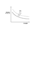
- FIG. 4 is a diagram showing the relationship between the internal resistance value of the storage battery and the temperature.
- the controller 30 stores in advance an initial value Rini of an internal resistance value corresponding to a plurality of temperatures of the storage battery 10 (hereinafter referred to as an internal resistance initial value Rini) in the storage unit 32.
- an internal resistance initial value Rini an initial value of an internal resistance value corresponding to a plurality of temperatures of the storage battery 10
- the internal resistance initial value Rini an initial value of an internal resistance value corresponding to a plurality of temperatures of the storage battery 10
- Rini an initial value of an internal resistance value corresponding to a plurality of temperatures of the storage battery 10
- the internal resistance initial value Rini also changes according to the temperature of the storage battery 10. Therefore, by using the internal resistance initial value Rini of the storage battery 10 at the same temperature as the temperature of the storage battery 10 when the current internal resistance value is calculated, it is possible to calculate the deterioration rate ⁇ with high accuracy.
- the internal resistance value calculation unit 35 immediately before determining that the current and current current parameter values have fluctuated by a predetermined value or more immediately before the internal resistance initial value of the storage battery 10 at the same temperature as the temperature indicated by the newly acquired temperature parameter value.
- the value Rini is calculated.
- the internal resistance value calculation unit 35 reads the internal resistance initial value Rini corresponding to a plurality of temperatures in the vicinity of the temperature indicated by the newly acquired temperature parameter value from the storage unit 32, and newly acquires it by interpolation calculation or the like. The internal resistance initial value Rini corresponding to the temperature parameter is calculated. Then, the internal resistance value calculation unit 35 outputs the calculated internal resistance value R and the internal resistance initial value Rini to the battery deterioration information processing unit 33. Then, the battery deterioration information processing unit 33 calculates the current deterioration rate ⁇ of the storage battery 10 using the above-described deterioration rate value calculation formula.
- the battery deterioration information processing part 33 inputs and acquires the internal resistance value R and the internal resistance initial value Rini calculated by the internal resistance value calculation part 35 from the internal resistance value calculation part 35 every predetermined period, The deterioration rate ⁇ is calculated and output to the display device 40. At this time, when a plurality of deterioration rates ⁇ are calculated within the predetermined period, the battery deterioration information processing unit 33 outputs the average value to the display device 40.
- the display device 40 displays the deterioration rate ⁇ acquired by inputting from the controller 30 on a monitor or the like.
- the battery deterioration information processing unit 33 Is determined to be a lifetime, and warning information is output to the display device 40. Then, the display device 40 informs the user of the storage battery by turning on the abnormal lamp 401 or the like.
- the battery deterioration information processing unit 33 reads the limit deterioration rate ⁇ limit from the storage unit 32 and determines whether the calculated deterioration rate ⁇ and the average value are equal to or higher than the limit deterioration rate ⁇ limit. Compare with the deterioration rate ⁇ and its average value.
- the current parameter value, voltage parameter value, and temperature parameter value of the storage battery 10 are intermittently obtained, and the internal resistance value R at that time is calculated using these parameter values.
- the deterioration rate of 10 is calculated, and it is determined whether the deterioration rate ⁇ is equal to or greater than the limit deterioration rate ⁇ limit. Therefore, the deterioration state of the battery can be detected regardless of the load pattern of the storage battery 10.
- the display device 40 can display a highly accurate deterioration state of the storage battery 10, it is possible to prevent occurrence of excessive cost due to early replacement of the storage battery 10 or malfunction due to replacement delay at a more appropriate timing. Is possible.
- the internal resistance value Rlimit when the storage battery 10 is to be determined to have a lifetime is the open circuit voltage when the storage battery 10 is assumed to have a maximum SOC (state of charge) during operation.
- V_VOCmax the maximum current design value flowing into the storage battery 10 during charging is Icmax
- the voltage value applied to the storage battery 10 during operation V_VOCmax + (Icmax ⁇ Rlimit)
- Idmax the maximum current design value flowing into the storage battery 10 during discharge
- V_VOCmin the open circuit voltage when Id and the maximum current design value flowing into the storage battery 10 during discharge is Idmax
- , where Pcmax is the maximum charge power design value, which is a characteristic of the storage battery 10, and Vmin is the minimum battery voltage design value. Is a value calculated by. Further, the maximum design current value Idmax flowing into the storage battery 10 at the time of discharging is calculated as Icmax
- the battery deterioration information processing unit 33 compares the voltage parameter value acquired by input from the parameter acquisition unit 31 with the allowable voltage value of the storage battery 10 recorded in the storage unit 32 to determine the voltage Even when the parameter value exceeds the allowable voltage value, it is determined that the life of the storage battery is reached, and warning information is output to the display device 40. Also at this time, the display device 40 informs the user that the storage battery is over by, for example, turning on the abnormal lamp 401.
- the battery deterioration information processing unit 33 compares the current parameter value acquired last time with the current parameter value acquired from the current parameter acquisition unit 31, and determines whether or not the value has changed by a certain value or more. When it is determined that the current parameter value fluctuates by a certain value or more, the internal resistance value of the storage battery 10 is calculated. However, the battery deterioration information processing unit 33 further defines the fluctuation of the current parameter value flowing into and out of the secondary battery 11 constituting the storage battery 10 immediately before determining that the current parameter value fluctuates more than a certain value. You may make it calculate the internal resistance value of the storage battery 10 only when the state below a value continues more than the fixed time t.
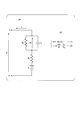
- FIG. 5 is a diagram showing an equivalent circuit of the secondary battery. That is, as shown in this figure, the secondary battery 11 constituting the storage battery 10 includes a capacitor component. Immediately after the current changes, the secondary battery 11 is affected by the voltage Vc of the capacitor component and is detected by ⁇ V / ⁇ I. Variations in internal resistance value increase. Therefore, in order to reduce this variation, the storage battery 10 is configured only when a change in the current parameter value flowing into and out of the secondary battery 11 that constitutes the storage battery 10 continues for a predetermined time t or longer. It is desirable to calculate the internal resistance value of the secondary battery 11. Note that the value of the predetermined time t only needs to be larger than the time constant of the CR circuit shown in FIG. Thereby, the detection accuracy of the internal resistance value R and the deterioration rate ⁇ is further improved, and the accuracy of determination of the deterioration state of the storage battery 10 can be improved.
- FIG. 6 is a graph showing the relationship between the operation days of the storage battery and the deterioration rate.
- the deterioration acceleration coefficient k can be calculated from the above square root law equation, the current operation days N, and the deterioration rate ⁇ . Further, using this deterioration acceleration coefficient k and the limit deterioration rate ⁇ limit, the life determination days Nlimit when the deterioration rate becomes ⁇ limit can be calculated.
- the remaining life days calculation unit 34 of the controller 30 calculates the life determination days Nlimit at a predetermined timing and records it in the storage unit 32. And the remaining life days calculation part 34 records the elapsed days from the time of the operation start of the storage battery 10 at any time, for example in the memory
- the remaining life days calculation unit 34 outputs the calculated remaining life days to the display device 40.
- the display device 40 displays the remaining life on the monitor.
- the deterioration rate is calculated for each secondary battery 11, whether it is a lifetime, or the remaining life days are calculated. You can do it.
- the internal resistance value of the storage battery 10 (each of the two secondary batteries 11 calculated as a group) is calculated. By using the total internal resistance value of the secondary battery 11) and the deterioration rate (average value of the deterioration rate of each secondary battery), it is determined whether or not the battery life is 10 units, and the remaining life days are calculated. Also good.
- the controller 30 and the display device 40 of the battery deterioration detection device 1 described above have a computer system inside.
- Each process described above is stored in a computer-readable recording medium in the form of a program, and the above process is performed by the computer reading and executing the program.
- the computer-readable recording medium means a magnetic disk, a magneto-optical disk, a CD-ROM, a DVD-ROM, a semiconductor memory, or the like.
- the computer program may be distributed to the computer via a communication line, and the computer that has received the distribution may execute the program.
- the program may be for realizing a part of the functions described above. Furthermore, what can implement
- the current parameter value, voltage parameter value, and temperature parameter value of the storage battery are intermittently obtained, and the internal resistance value at that time is calculated using the parameter values, and the deterioration rate of the storage battery is calculated. At the same time, it is determined whether the deterioration rate is equal to or higher than the limit deterioration rate using the accurate deterioration rate. Therefore, the deterioration state of the battery can be detected regardless of the load pattern of the storage battery.
Landscapes
- Physics & Mathematics (AREA)
- General Physics & Mathematics (AREA)
- Tests Of Electric Status Of Batteries (AREA)
- Charge And Discharge Circuits For Batteries Or The Like (AREA)
- Secondary Cells (AREA)
- Electric Propulsion And Braking For Vehicles (AREA)
Abstract
Description
本願は、2010年8月5日に日本出願された特願2010-176565に基づいて優先権を主張し、その内容をここに援用する。
また、蓄電池の温度が変化する環境で電流や電圧から劣化度合いを推定する場合、温度が電池特性に与える影響を排除する必要がある。
図1は、同実施形態による電池劣化検知装置の構成を示すブロック図である。
本実施形態において電池劣化検知装置1は、例えば蓄電池に蓄積された電力に基づいて動作するRTG(Rubber Tired Gantry crane)や、APM(Automated People Mover)、LRT(Light Rail Transit)などの新交通システムの車両等に備えられている。
そして、当該電池劣化検知装置1は、蓄電池10、BMS(Battery Management System)20、コントローラ(Programmable Logic Controller)30、表示装置40、電力負荷50を備えている。
電力負荷50は、例えば車両の車輪に接続された電気モータやインバータ等の電力変換器である。電力負荷50は、ワイパーなどを駆動する電気モータであってもよい。
図1に示すとおり、電池劣化検知装置1のBMS20は、CMU(Cell Monitor Unit)21と、BMU(Battery Management Unit)23を含んで構成される。
ここで、CMU21は、図示しないADC(Analog Digital Converter)を備えており、上記各種センサーが検知して出力する複数の上記計測情報をそれぞれアナログ信号として受け、これらアナログ信号をADCによってそれぞれに対応するデジタル信号に変換した後、上記関連情報を算出するための複数のパラメータとしてBMU23へ出力している。そして、本実施形態においては、図1に示すように、CMU21が二次電池11と信号線により接続されている。
なお、ここでは、CMU21は1つだけ示されているが、この態様に限定されない。例えば蓄電池10が複数の二次電池11によって構成されている場合には、CMU21を複数備えて、各CMU21に複数個ずつ二次電池11を接続してもよいし、複数の二次電池11に対して一対一の関係でCMU21が備わっていてもよい。すなわち、BMU23が劣化率算出処理や残寿命日数算出処理を行うために必要となる複数のパラメータをCMU21から取得できるのであれば、CMU21の個数はいくつであってもよい。CMU21を含んでBMU23が構成されるのであれば、BMS20はBMU23のみで構成されてもよい。
次に、図2を用いてBMS20の内部構成および動作を詳述する。
図2に示すように、蓄電池10を構成する二次電池11に対して電圧計3が設けられている。具体的には、二次電池11の正極端子と負極端子との間に電圧計3が接続されている。そして、CMU21は、パラメータ値検出部211を備え、当該パラメータ値検出部211は電圧計3が計測し且つ出力した計測情報としての電圧値をアナログ信号として取得する(当該アナログ信号がパラメータ値検出部211に入力される)。
また、蓄電池10を構成する二次電池11の筐体には温度計4が取り付けられている。
そして、上記パラメータ値検出部211は、温度計4が計測し且つ出力した計測情報としての温度値をアナログ信号として取得する(当該アナログ信号がパラメータ値検出部211に入力される)。
図3に示すように、コントローラ30は、パラメータ取得部31、記憶部32(内部抵抗初期値記憶部)、劣化率算出処理を行う電池劣化情報処理部33、残寿命日数算出処理を行う残寿命日数算出部34、蓄電池10の内部抵抗値を算出する内部抵抗値算出部35を備えている。
まず、パラメータ取得部31は、蓄電池10内に設けられた二次電池11の端子間電圧値(二次電池11における正極端子と負極端子の間の電圧値)に相当するパラメータの値(二次電池11の当該電圧のパラメータを端子間電圧パラメータVといい、その値を端子間電圧パラメータ値という)を、BMS20から入力して取得する。
また、パラメータ取得部31は、電流計2より計測された蓄電池10に入出流する電流値に相当するパラメータの値(当該パラメータを電流パラメータIといい、この値を電流パラメータ値という)をBMS20から入力して取得する。
また、パラメータ取得部31は、温度計4より計測された蓄電池10を構成する二次電池11の筐体の温度のパラメータの値(当該パラメータを温度パラメータTといい、この値を温度パラメータ値という)をBMS20から入力して取得する。
そして、パラメータ取得部31は、取得した電流パラメータ値、電圧パラメータ値、温度パラメータ値を内部抵抗値算出部35へ出力し、また記憶部32に記録する。
そして、内部抵抗値算出部35は、前回と今回の電流パラメータ値が一定の値以上変動していると判定した場合には、蓄電池10の内部抵抗値を算出する。なお、前回と今回の電流パラメータ値が一定の値以上変動していない場合には、蓄電池10の内部抵抗の算出時にノイズが混入してしまう可能性がある。従って、前回と今回の電流パラメータ値が一定値以上変動していない場合には、内部抵抗値算出部35は、蓄電池10の内部抵抗値の算出を停止する。なおこの内部抵抗値の算出の処理において、内部抵抗値算出部35は、前回と今回の電流パラメータ値の差を算出して電流パラメータ値の変動値ΔIを得、また、前回と今回の電圧パラメータ値の差を算出して電圧パラメータ値の変動値ΔVを得る。そして、内部抵抗値算出部35は、算出したΔIが一定値以上であるかを判定し、一定値以上であれば、蓄電池10の内部抵抗値Rを、電流パラメータ値の変動値ΔIと、当該電流パラメータ値が変動した際の電圧パラメータ値の変動値ΔVとを用いて、R=ΔV÷ΔIにより算出する。
コントローラ30は、予め記憶部32に蓄電池10の複数の温度に応じた内部抵抗値の初期値Rini(以降、内部抵抗初期値Riniと呼ぶこととする)を記憶している。ここで、図4で示すように、蓄電池10の内部抵抗値は、温度が上昇するに従って、反比例的に内部抵抗値が低くなることが知られている。また図4で示すように、蓄電池10の内部抵抗値は、当該蓄電池10が劣化するに従って、矢印方向にその抵抗の特性(内部抵抗値と温度との関係)が変化することが知られている。つまり、蓄電池10が劣化すると、同じ温度であっても、劣化前と比べて内部抵抗値が増加することが知られている。
そして、電池劣化情報処理部33は、所定の期間ごとに、内部抵抗値算出部35から当該内部抵抗値算出部35の算出した内部抵抗値Rと内部抵抗初期値Riniを入力して取得し、劣化率γを算出して表示装置40へ出力する。このとき、当該所定期間内に複数の劣化率γを算出するような場合には、電池劣化情報処理部33は、その平均値を表示装置40へ出力する。表示装置40はコントローラ30から入力して取得した劣化率γをモニタ等に表示する。
また、現在の内部抵抗値を算出した際の蓄電池10の温度と同一の温度であるときの蓄電池10の内部抵抗初期値Riniを用いることにより、精度のよい劣化率γを算出し、その劣化率γを用いて限界劣化率γlimit以上となったかを判定している。従って、温度が蓄電池の内部抵抗に与える影響を排除して劣化状態を検知するため、精度よく劣化状態を判定することができる。
また、蓄電池10の精度の良い劣化状態を表示装置40で表示することが出来るため、蓄電池10の早期交換による過剰コストの発生や、交換遅延による不具合を未然に、より適切なタイミングで防止することが可能となる。
限界劣化率γlimitは、蓄電池10の内部抵抗初期値Riniに対する、蓄電池10が寿命であると判定されるべき状態である時の内部抵抗値Rlimitの割合であり、γlimit=Rrimit÷Riniで計算することが出来る。ここで、蓄電池10が寿命であると判定されるべき状態である時の内部抵抗値Rlimitは、運用時に想定される蓄電池10の最大SOC(state of charge;充電率)であるときの開回路電圧をV_VOCmax、充電時に蓄電池10に流入する最大電流設計値をIcmaxとした場合における、運用時の蓄電池10にかかる電圧値=V_VOCmax+(Icmax×Rlimit)、または、運用時に想定される蓄電池10の最小SOCであるときの開回路電圧をV_VOCmin、放電時に蓄電池10に流入する最大電流設計値をIdmaxとした場合における、運用時の蓄電池10にかかる電圧値=V_VOCmin-(Idmax×Rlimit)の何れかが、蓄電池10の許容電圧値を外れる時の内部抵抗値である。
つまり、この図で示すように蓄電池10を構成する二次電池11はコンデンサ成分を包含しており、電流変化のあった直後はコンデンサ成分の電圧Vcの影響を受け、ΔV/ΔIで検出される内部抵抗値のバラツキが大きくなる。従って、このばらつきを小さくするために、蓄電池10を構成する二次電池11に入出流する電流パラメータ値の変動が規定値以下の状態が一定時間t以上続いた場合にのみ、蓄電池10を構成する二次電池11の内部抵抗値を算出することが望ましい、なお、この一定時間tの値は、図5で示すCR回路の時定数よりも大きければよい。
これにより、さらに、内部抵抗値Rや劣化率γの検知精度が向上し、蓄電池10の劣化状態の判定の精度を向上させることができる。
この図が示すように、蓄電池10の運用日数が増加するにつれて、蓄電池10の劣化率γが、限界劣化率γlimit(寿命判定値)に近づいていく。より具体的には、運用日数と劣化率の関係は、蓄電池10の内部抵抗の上昇が充放電のサイクル数や運用日数の平方根に比例するという平方根則に基づくことが知られており、平方根測式γ=1+k√Nで表される。なお、Nは運用日数、kは劣化加速係数を表し、運用開始時はγ=1.0である。
ここで、上記平方根則式と、現在の運用日数Nと劣化率γとから、劣化加速係数kを算出することができる。またこの劣化加速係数kと限界劣化率γlimitとを用いて、劣化率がγlimitとなる際の寿命判定日数Nlimitを算出することができる。コントローラ30の残寿命日数算出部34は、この寿命判定日数Nlimitを、ある定められたタイミングで算出し、記憶部32に記録する。そして、残寿命日数算出部34は、例えば、蓄電池10の運用開始時からの経過日数を記憶部32に随時記録しており、算出した寿命判定日数Nlimitから、記憶部32に記録されている経過日数を減算して、残寿命日数を算出する。そして、残寿命日数算出部34は、算出した残寿命日数を表示装置40へ出力する。これにより表示装置40は残寿命日数をモニタに表示する。
このような処理により、ユーザに予測算寿命日数を通知することができ、より容易に、蓄電池の早期交換による過剰コストの発生や、交換遅延による不具合を未然に防止することができる。
なお、上述の処理において、ある定められたタイミングで寿命判定日数Nlimitを算出しているが、所定の間隔で、複数の寿命判定日数Nlimitを求め、最新の寿命判定日数Nlimitを用いて、そのときの蓄電池10の状態で示される残寿命日数を算出するようにしてもよい。
さらに、前述した機能をコンピュータシステムにすでに記録されているプログラムとの組み合わせで実現できるもの、いわゆる差分ファイル(差分プログラム)であっても良い。
2・・・電流計、
3・・・電圧計、
4・・・温度計、
10・・・蓄電池、
11・・・二次電池、
20・・・BMS、
21・・・CMU、
23・・・BMU、
30・・・コントローラ、
31・・・パラメータ取得部、
32・・・記憶部、
33・・・電池劣化情報処理部、
34・・・残寿命日数算出部、
35・・・内部抵抗値算出部、
40・・・表示装置、
50・・・電力負荷
Claims (7)
- 蓄電池に入出力する電流値と、前記蓄電池にかかる電圧値とを取得し、前記電流値が一定値以上変動した場合の当該電流値の変動幅と、そのときの前記電圧値の変動幅とを用いて前記蓄電池の現在の内部抵抗値を算出する内部抵抗値算出部と、
前記現在の内部抵抗値を、前記蓄電池の現在の温度に対応する内部抵抗初期値により除して、前記蓄電池の現在の温度における当該蓄電池の劣化率を算出し、当該劣化率をモニタ装置へ出力する電池劣化情報処理部と、
を備えることを特徴とする電池劣化検知装置。 - 前記内部抵抗値算出部は、前記電流値が一定値以上変動する前の所定の期間、前記蓄電池に入出流する電流の変動が規定値以下となる状態が続いた場合に、前記現在の内部抵抗値を算出する
ことを特徴とする請求項1に記載の電池劣化検知装置。 - 前記蓄電池の異なる温度それぞれにおける内部抵抗初期値を記憶する内部抵抗初期値記憶部と、を備え、
前記内部抵抗値算出部は、前記取得した前記蓄電池の温度に対応する内部抵抗初期値を、前記内部抵抗初期値記憶部に記録されている異なる温度それぞれにおける内部抵抗初期値に基づいて算出する
ことを特徴とする請求項1または請求項2に記載の電池劣化検知装置。 - 前記電池劣化情報処理部は、算出した複数の劣化率の平均を算出して、当該劣化率の平均値を前記モニタ装置へ出力する
ことを特徴とする請求項1から請求項3の何れか一項に記載の電池劣化検知装置。 - 前記蓄電池の運用日数と劣化率との関係を示す平方根則と、前記蓄電池が寿命と判定されるべき状態での当該蓄電池の内部抵抗値における前記劣化率とを用いて、前記蓄電池が寿命と判断される寿命判定日数を算出し、当該寿命判定日数から現在の運用日数を減じて、前記蓄電池の残寿命日数を算出する残寿命日数算出部と、
を備えることを特徴とする請求項1から請求項4の何れか一項に記載の電池劣化検知装置。 - 電池劣化検知装置の電池劣化検知方法であって、
蓄電池に入出力する電流値と、前記蓄電池にかかる電圧値とを取得し、前記電流値が一定値以上変動した場合の当該電流値の変動幅と、そのときの前記電圧値の変動幅とを用いて前記蓄電池の現在の内部抵抗値を算出し、
前記現在の内部抵抗値を、前記蓄電池の現在の温度に対応する内部抵抗初期値により除して、前記蓄電池の現在の温度における当該蓄電池の劣化率を算出し、当該劣化率をモニタ装置へ出力する
ことを特徴とする電池劣化検知方法。 - 電池劣化検知装置のコンピュータを、
蓄電池に入出力する電流値と、前記蓄電池にかかる電圧値とを取得し、前記電流値が一定値以上変動した場合の当該電流値の変動幅と、そのときの前記電圧値の変動幅とを用いて前記蓄電池の現在の内部抵抗値を算出する内部抵抗値算出処理、
前記現在の内部抵抗値を、前記蓄電池の現在の温度に対応する内部抵抗初期値により除して、前記蓄電池の現在の温度における当該蓄電池の劣化率を算出し、当該劣化率をモニタ装置へ出力する電池劣化情報処理、
として機能させることを特徴とするプログラム。
Priority Applications (1)
| Application Number | Priority Date | Filing Date | Title |
|---|---|---|---|
| CN201180034365.0A CN103080762B (zh) | 2010-08-05 | 2011-08-02 | 电池劣化检测装置、电池劣化检测方法及其程序 |
Applications Claiming Priority (2)
| Application Number | Priority Date | Filing Date | Title |
|---|---|---|---|
| JP2010176565A JP5777303B2 (ja) | 2010-08-05 | 2010-08-05 | 電池劣化検知装置および電池劣化検知方法ならびにそのプログラム |
| JP2010-176565 | 2010-08-05 |
Publications (1)
| Publication Number | Publication Date |
|---|---|
| WO2012018028A1 true WO2012018028A1 (ja) | 2012-02-09 |
Family
ID=45559525
Family Applications (1)
| Application Number | Title | Priority Date | Filing Date |
|---|---|---|---|
| PCT/JP2011/067709 Ceased WO2012018028A1 (ja) | 2010-08-05 | 2011-08-02 | 電池劣化検知装置および電池劣化検知方法ならびにそのプログラム |
Country Status (3)
| Country | Link |
|---|---|
| JP (1) | JP5777303B2 (ja) |
| CN (1) | CN103080762B (ja) |
| WO (1) | WO2012018028A1 (ja) |
Cited By (4)
| Publication number | Priority date | Publication date | Assignee | Title |
|---|---|---|---|---|
| CN103543407A (zh) * | 2012-07-12 | 2014-01-29 | 丰田自动车株式会社 | 用于固定式蓄电池的剩余寿命确定系统以及确定固定式蓄电池的剩余寿命的方法 |
| CN103576098A (zh) * | 2012-07-19 | 2014-02-12 | 华为技术有限公司 | 一种电源寿命在线监测方法、系统及电源 |
| WO2016079913A1 (ja) * | 2014-11-19 | 2016-05-26 | 株式会社 東芝 | 蓄電池管理システム及び蓄電池管理方法 |
| CN121049758A (zh) * | 2025-08-22 | 2025-12-02 | 东莞市昂跃电子有限公司 | 一种新型大电流电池 |
Families Citing this family (31)
| Publication number | Priority date | Publication date | Assignee | Title |
|---|---|---|---|---|
| KR101498764B1 (ko) * | 2012-05-10 | 2015-03-04 | 주식회사 엘지화학 | 배터리의 저항측정방법 및 장치, 이를 이용한 배터리 관리 시스템 |
| JP5994521B2 (ja) | 2012-09-21 | 2016-09-21 | 株式会社Gsユアサ | 状態推定装置、開放電圧特性生成方法 |
| JP6197479B2 (ja) * | 2013-08-23 | 2017-09-20 | トヨタ自動車株式会社 | 蓄電システム及び蓄電装置の満充電容量推定方法 |
| JP6180249B2 (ja) * | 2013-09-18 | 2017-08-16 | Kyb株式会社 | 電池容量推定装置及び電池容量推定方法 |
| JP6148144B2 (ja) * | 2013-10-03 | 2017-06-14 | 三菱重工業株式会社 | 劣化率特定装置、劣化率特定方法、及びプログラム |
| JP6165620B2 (ja) * | 2013-12-19 | 2017-07-19 | 日立オートモティブシステムズ株式会社 | 二次電池モジュールおよび二次電池監視装置 |
| JP6443656B2 (ja) * | 2014-07-02 | 2018-12-26 | パナソニックIpマネジメント株式会社 | 電池状態判定装置 |
| CN104865445A (zh) * | 2014-08-29 | 2015-08-26 | 北汽福田汽车股份有限公司 | 一种动力电池内阻检测方法及动力电池健康度诊断方法 |
| CN105467324B (zh) | 2014-09-30 | 2020-03-03 | 株式会社杰士汤浅国际 | 电池劣化判定装置、电池劣化判定方法以及电池组 |
| CN104267367A (zh) * | 2014-10-29 | 2015-01-07 | 安徽鑫龙电器股份有限公司 | 一种蓄电池监测装置的误差检测方法 |
| JP6593769B2 (ja) * | 2015-03-09 | 2019-10-23 | 中国電力株式会社 | 蓄電池残寿命推定方法、蓄電池点検日決定方法、蓄電池残寿命推定装置、及び蓄電池残寿命推定システム |
| JP6671016B2 (ja) * | 2015-03-09 | 2020-03-25 | パナソニックIpマネジメント株式会社 | 貸与システムおよび貸与管理方法 |
| WO2016194271A1 (ja) * | 2015-06-05 | 2016-12-08 | パナソニックIpマネジメント株式会社 | 補機用バッテリの状態判定装置、及び、補機用バッテリの状態判定方法 |
| CN106707029B (zh) * | 2015-11-13 | 2020-10-23 | 北京宝沃汽车股份有限公司 | 一种动力电池内阻值计算方法和健康度确定方法及装置 |
| CN105699774B (zh) * | 2016-01-30 | 2020-12-08 | 埃斯倍风电科技(青岛)有限公司 | 一种变桨系统电池组内阻初始值的校准方法 |
| JP2018179733A (ja) * | 2017-04-12 | 2018-11-15 | 日立化成株式会社 | 電池の寿命診断装置及び電池の寿命診断方法 |
| JP6881154B2 (ja) * | 2017-08-23 | 2021-06-02 | トヨタ自動車株式会社 | 二次電池の劣化状態推定方法および二次電池システム |
| JP7006359B2 (ja) * | 2018-02-21 | 2022-01-24 | トヨタ自動車株式会社 | 電池の発煙判定方法および電池システム |
| JP6977687B2 (ja) * | 2018-08-21 | 2021-12-08 | トヨタ自動車株式会社 | 蓄電デバイスの検査方法および製造方法 |
| JP6973334B2 (ja) * | 2018-08-30 | 2021-11-24 | トヨタ自動車株式会社 | 二次電池の劣化状態推定方法および二次電池システム |
| CN109615043B (zh) * | 2018-12-13 | 2022-04-22 | 吴泽忠 | 可监控统计汽车故障情况的管理系统 |
| US12296714B2 (en) * | 2019-06-12 | 2025-05-13 | Mitsubishi Electric Corporation | Charge and discharge control device and charge and discharge control method including first, second, and third charge level ranges |
| CN110261791B (zh) * | 2019-07-22 | 2021-11-30 | 天能电池集团股份有限公司 | 一种蓄电池组循环寿命快速评价方法 |
| CN113125979A (zh) * | 2019-12-31 | 2021-07-16 | 华为技术有限公司 | 一种蓄电池内阻检测装置及方法 |
| WO2021162077A1 (ja) * | 2020-02-12 | 2021-08-19 | 古河電気工業株式会社 | 蓄電池システムの劣化判定装置、蓄電池システムの劣化判定方法、蓄電池システム及び蓄電池監視装置 |
| JP6960488B2 (ja) * | 2020-03-03 | 2021-11-05 | 本田技研工業株式会社 | 電動車両、表示方法 |
| JP7086495B2 (ja) * | 2020-04-09 | 2022-06-20 | 矢崎総業株式会社 | 電池監視装置 |
| JP7314855B2 (ja) | 2020-04-21 | 2023-07-26 | トヨタ自動車株式会社 | 組電池の状態判定装置および状態判定方法 |
| CN111366866B (zh) * | 2020-04-22 | 2023-09-01 | 珠海新金珠电力设备有限公司 | 一种测量蓄电池寿命周期的监控装置及计算方法 |
| JP2023168173A (ja) * | 2022-05-13 | 2023-11-24 | 東芝Itコントロールシステム株式会社 | 電池寿命予告診断装置 |
| JP7816120B2 (ja) * | 2022-12-15 | 2026-02-18 | トヨタ自動車株式会社 | 冗長電源の診断方法およびプログラム |
Citations (5)
| Publication number | Priority date | Publication date | Assignee | Title |
|---|---|---|---|---|
| JP2000223164A (ja) * | 1999-01-29 | 2000-08-11 | Ntt Docomo Inc | 電池パックおよび該電池パックの容量劣化診断方法と装置 |
| JP2005156352A (ja) * | 2003-11-26 | 2005-06-16 | Nissan Motor Co Ltd | バッテリの開放電圧演算方法および充電量演算方法 |
| WO2006022073A1 (ja) * | 2004-08-25 | 2006-03-02 | Nec Corporation | 内部インピーダンス検出装置、内部インピーダンス検出方法、劣化度検出装置および劣化度検出方法 |
| JP2007057434A (ja) * | 2005-08-25 | 2007-03-08 | Fuji Heavy Ind Ltd | 蓄電デバイスの劣化状態推定システム |
| JP2007121030A (ja) * | 2005-10-26 | 2007-05-17 | Denso Corp | 車両用蓄電装置の内部状態検出装置 |
Family Cites Families (2)
| Publication number | Priority date | Publication date | Assignee | Title |
|---|---|---|---|---|
| JP4066732B2 (ja) * | 2002-07-12 | 2008-03-26 | 新神戸電機株式会社 | バッテリ残容量推定方法 |
| JP2010019758A (ja) * | 2008-07-11 | 2010-01-28 | Mitsumi Electric Co Ltd | 電池状態検知装置 |
-
2010
- 2010-08-05 JP JP2010176565A patent/JP5777303B2/ja active Active
-
2011
- 2011-08-02 WO PCT/JP2011/067709 patent/WO2012018028A1/ja not_active Ceased
- 2011-08-02 CN CN201180034365.0A patent/CN103080762B/zh not_active Expired - Fee Related
Patent Citations (5)
| Publication number | Priority date | Publication date | Assignee | Title |
|---|---|---|---|---|
| JP2000223164A (ja) * | 1999-01-29 | 2000-08-11 | Ntt Docomo Inc | 電池パックおよび該電池パックの容量劣化診断方法と装置 |
| JP2005156352A (ja) * | 2003-11-26 | 2005-06-16 | Nissan Motor Co Ltd | バッテリの開放電圧演算方法および充電量演算方法 |
| WO2006022073A1 (ja) * | 2004-08-25 | 2006-03-02 | Nec Corporation | 内部インピーダンス検出装置、内部インピーダンス検出方法、劣化度検出装置および劣化度検出方法 |
| JP2007057434A (ja) * | 2005-08-25 | 2007-03-08 | Fuji Heavy Ind Ltd | 蓄電デバイスの劣化状態推定システム |
| JP2007121030A (ja) * | 2005-10-26 | 2007-05-17 | Denso Corp | 車両用蓄電装置の内部状態検出装置 |
Cited By (4)
| Publication number | Priority date | Publication date | Assignee | Title |
|---|---|---|---|---|
| CN103543407A (zh) * | 2012-07-12 | 2014-01-29 | 丰田自动车株式会社 | 用于固定式蓄电池的剩余寿命确定系统以及确定固定式蓄电池的剩余寿命的方法 |
| CN103576098A (zh) * | 2012-07-19 | 2014-02-12 | 华为技术有限公司 | 一种电源寿命在线监测方法、系统及电源 |
| WO2016079913A1 (ja) * | 2014-11-19 | 2016-05-26 | 株式会社 東芝 | 蓄電池管理システム及び蓄電池管理方法 |
| CN121049758A (zh) * | 2025-08-22 | 2025-12-02 | 东莞市昂跃电子有限公司 | 一种新型大电流电池 |
Also Published As
| Publication number | Publication date |
|---|---|
| JP5777303B2 (ja) | 2015-09-09 |
| CN103080762A (zh) | 2013-05-01 |
| JP2012037337A (ja) | 2012-02-23 |
| CN103080762B (zh) | 2016-01-20 |
Similar Documents
| Publication | Publication Date | Title |
|---|---|---|
| JP5777303B2 (ja) | 電池劣化検知装置および電池劣化検知方法ならびにそのプログラム | |
| JP5174111B2 (ja) | 電池システム | |
| KR101288671B1 (ko) | 전지 시스템 | |
| JP5260695B2 (ja) | 二次電池寿命予測装置、電池システム、及び二次電池寿命予測方法 | |
| JP6317031B2 (ja) | 電池制御装置、および、車両システム | |
| KR101943091B1 (ko) | 전기 화학적 배터리 전지의 건강 상태를 판정하는 시스템 및 방법 | |
| CN106662620B (zh) | 电池状态探测装置、二次电池系统、存储介质、电池状态探测方法 | |
| JP7167062B2 (ja) | 充電可能電池異常検出装置および充電可能電池異常検出方法 | |
| US20080224709A1 (en) | Battery management system and driving method thereof | |
| EP3002597A1 (en) | Battery control device | |
| US20130158917A1 (en) | Battery abnormality prediction system | |
| WO2014027389A1 (ja) | 電池制御装置、二次電池システム | |
| JP5812968B2 (ja) | 電流センサ故障検知装置、電池システム、及び電流センサ故障検知方法 | |
| JP2016023968A (ja) | 電池状態検知装置、二次電池システム、電池状態検知プログラム、電池状態検知方法 | |
| JP2011076746A (ja) | 二次電池異常予見システム | |
| JP2012019577A (ja) | 電池システム | |
| EP3605123B1 (en) | Storage battery control device and control method | |
| JP5911407B2 (ja) | バッテリの健全度算出装置および健全度算出方法 | |
| JP2010281723A (ja) | 蓄電デバイスの状態検知方法及びその装置 | |
| JP2013145198A (ja) | 測定値補正装置 | |
| JP2012095388A (ja) | 電池状態監視装置 | |
| JP2019070622A (ja) | 二次電池システム | |
| RU109922U1 (ru) | Устройство контроля остаточной емкости аккумуляторной батареи транспортного средства | |
| EP4720695A1 (en) | Method and apparatus for measuring the aging state of batteries of electrochemical accumulators |
Legal Events
| Date | Code | Title | Description |
|---|---|---|---|
| WWE | Wipo information: entry into national phase |
Ref document number: 201180034365.0 Country of ref document: CN |
|
| 121 | Ep: the epo has been informed by wipo that ep was designated in this application |
Ref document number: 11814653 Country of ref document: EP Kind code of ref document: A1 |
|
| WWE | Wipo information: entry into national phase |
Ref document number: 10754/CHENP/2012 Country of ref document: IN |
|
| NENP | Non-entry into the national phase |
Ref country code: DE |
|
| 122 | Ep: pct application non-entry in european phase |
Ref document number: 11814653 Country of ref document: EP Kind code of ref document: A1 |