WO2012017886A1 - ステアバイワイヤ式操舵装置の反力トルクアクチュエータ - Google Patents
ステアバイワイヤ式操舵装置の反力トルクアクチュエータ Download PDFInfo
- Publication number
- WO2012017886A1 WO2012017886A1 PCT/JP2011/067054 JP2011067054W WO2012017886A1 WO 2012017886 A1 WO2012017886 A1 WO 2012017886A1 JP 2011067054 W JP2011067054 W JP 2011067054W WO 2012017886 A1 WO2012017886 A1 WO 2012017886A1
- Authority
- WO
- WIPO (PCT)
- Prior art keywords
- steering
- reaction force
- rotation
- steer
- shaft
- Prior art date
- Legal status (The legal status is an assumption and is not a legal conclusion. Google has not performed a legal analysis and makes no representation as to the accuracy of the status listed.)
- Ceased
Links
Images




Classifications
-
- B—PERFORMING OPERATIONS; TRANSPORTING
- B62—LAND VEHICLES FOR TRAVELLING OTHERWISE THAN ON RAILS
- B62D—MOTOR VEHICLES; TRAILERS
- B62D5/00—Power-assisted or power-driven steering
- B62D5/001—Mechanical components or aspects of steer-by-wire systems, not otherwise provided for in this maingroup
- B62D5/005—Mechanical components or aspects of steer-by-wire systems, not otherwise provided for in this maingroup means for generating torque on steering wheel or input member, e.g. feedback
- B62D5/006—Mechanical components or aspects of steer-by-wire systems, not otherwise provided for in this maingroup means for generating torque on steering wheel or input member, e.g. feedback power actuated
Definitions
- the present invention relates to a reaction force torque actuator of a steer-by-wire type steering apparatus that is steered by a steering wheel that is not mechanically connected to a steering shaft for turning.
- reaction force torque acts on the rotation operation of the operation shaft of the steering wheel so that the operator who operates the steering wheel feels an appropriate response.
- a reaction force torque actuator that generates torque is provided.
- reaction force torque actuators those directly connected to a motor (for example, Patent Document 1), those using a speed reduction mechanism in which gears are arranged on a plurality of axes (for example, Patent Document 2), and those using a cycloid speed reduction mechanism (For example, patent document 3) etc. are proposed.
- the direct-coupled type reaction force torque actuator disclosed in Patent Document 1 is obtained by directly connecting a motor that is a reaction force generation source to an operation shaft of a steering wheel. In order to generate the same steering reaction force, there is a problem that a large motor must be used at high cost.
- reaction force torque actuator does not require high rotation and high torque is sufficient, it is sufficient to operate the steering wheel from a motor that is a reaction force generation source, like the reaction force torque actuator disclosed in Patent Document 2. It is effective to use a speed reduction mechanism for transmitting torque to the shaft.
- the reaction force torque actuator disclosed in Patent Document 2 uses a speed reduction mechanism in which gears are arranged on a plurality of axes, the size of the actuator increases, and the space occupied by the steering mechanism in the steer-by-wire steering device increases. There is a problem of doing.
- the reaction force torque actuator disclosed in Patent Document 3 uses a cycloid reduction mechanism as a reduction mechanism, so that space can be saved.
- vibration due to gear noise or backlash of the speed reduction mechanism, and motor cogging are amplified through the speed reduction mechanism, resulting in a problem that the steering feeling is lowered.
- a torque damper like the reaction force torque actuator disclosed in Patent Document 1.
- An object of the present invention is to provide a reaction force torque actuator for a steer-by-wire type steering apparatus that can be reduced in size and weight and can realize a steering feeling without a sense of incongruity.
- a reaction force torque actuator in a steer-by-wire type steering device is a reaction force torque actuator that performs steering with a steering wheel that is not mechanically connected to a steering shaft for turning and generates a steering reaction force on the steering wheel.
- a motor that is a source of the steering reaction force, a speed reduction mechanism that transmits the output of the motor as a reaction torque to the operation shaft of the steering wheel, and a variation in the reaction force torque transmitted to the operation shaft.
- a torque damper to be reduced, and the motor, the speed reduction mechanism, and the torque damper are arranged on the same axis as the operation shaft and connected in the arrangement order.
- the output of the motor is transmitted to the steering wheel operation shaft as a reaction force torque at a predetermined reduction ratio through the speed reduction mechanism, so that the steering reaction according to the steering angle is transmitted to the steering wheel.
- the motor, the speed reduction mechanism, and the torque damper are arranged and connected in the arrangement order on the same axis as the operation shaft of the steering wheel. And weight reduction is possible.
- a torque damper is provided to reduce fluctuations in the reaction torque transmitted to the steering wheel operating shaft. This reduces vibration due to motor cogging and gear noise in the speed reduction mechanism, and reduces steering force on the steering wheel.
- the ring can be prevented from lowering, and a steering feeling without discomfort can be realized.
- the speed reduction mechanism may be any one of a planetary gear speed reducer, a wave gear speed reducer, and a planetary roller speed reducer. These planetary gear reducers, wave gear reducers, and planetary roller reducers all provide a large reduction ratio and can be further reduced in size.
- a rotation limiting mechanism for limiting the range of rotation angle of the operation shaft of the steering wheel that can rotate may be provided on the same axis as the operation shaft.
- the steering wheel rotation limiting mechanism can be further reduced in size by being provided on the same axis as the operation shaft.
- the rotation limiting mechanism may be a planetary gear reducer, and the rotation limitation of the operation shaft may be performed at a rotating portion that is decelerated with respect to the rotation of the input shaft to which rotation is input from the operation shaft.
- the rotation limiting mechanism may be configured so that the rotation decelerated with respect to the rotation of the input shaft is used only for limiting the rotation of the operation shaft, and the rotation speed of the output shaft is the same as the rotation speed of the input shaft. good. If the decelerated rotation is used only for rotation limitation and the rotation speed of the output shaft is the same as the rotation speed of the input shaft, a single shaft can be used for the output shaft and the input shaft. Thereby, it becomes easy to provide the rotation limiting mechanism on the same axis as the operation shaft.
- the torque damper may be one in which a viscous fluid is sealed in a space of a housing that is sealed with an oil seal and through which an operation shaft of the steering wheel passes.
- the viscous fluid may be any one of silicon grease, silicon oil, and silicon gel. The torque damper using the viscous fluid is excellent in the effect of reducing the vibration caused by the cogging of the motor and the gear noise of the speed reduction mechanism, and can more effectively prevent the steering feeling from being lowered in the steering wheel.
- the outer diameter portion of the housing penetration portion of the operation shaft or the inner wall portion of the housing may be formed in a toothed shape.
- the “tooth cutting shape” refers to a shape divided into a plurality of tooth portions on which a plurality of surfaces are arranged. In this case, the frictional resistance between the operating shaft and the viscous fluid or the frictional resistance between the viscous fluid and the inner wall of the housing increases, so that the damper effect of the torque damper can be improved accordingly.
- a steering angle sensor for detecting the rotation angle of the operation shaft of the steering wheel may be provided.
- two or more systems of the steering angle sensors may be provided, and the failure mode may be detected by comparing the detection values of the steering angle sensors with each other.
- the motor, the speed reduction mechanism, and the torque damper may be covered with a sealed housing.
- FIG. 4 is a sectional view taken along line IV-IV in FIG. 1. It is a graph which shows the fluctuation
- FIG. 1 shows a schematic diagram of a reaction torque actuator of this embodiment
- FIG. 2 shows an external perspective view thereof.
- This reaction torque actuator is a steering reaction force applied to the steering wheel 1 in a steer-by-wire type steering apparatus that is steered by a steering wheel 1 that is not mechanically connected to a steering shaft (not shown) for turning.
- a device that generates The steering wheel 1 includes a handle 1a that is rotated by the driver and an operation shaft 1b that is positioned at the center of rotation and rotates integrally with the handle 1a.
- the operation shaft 1b is inserted into a sealed housing 9 formed by connecting four housing pieces 9a to 9d arranged in the axial direction, and is rotatably supported by the first housing piece 9a via bearings 21 and 22.
- the reaction force torque actuator includes a motor 2 that is a generation source of a steering reaction force, a speed reduction mechanism 3 that transmits an output of the motor 2 to the operation shaft 1b of the steering wheel 1 as a reaction force torque, and an operation shaft of the steering wheel 1.
- a rotation limiting mechanism 4 that limits the rotation of 1b and a torque damper 5 that reduces fluctuations in the reaction torque transmitted to the operation shaft 1b are provided.
- the motor 2, the speed reduction mechanism 3, the rotation limiting mechanism 4, and the torque damper 5 are connected in the arrangement order on the same axis as the operation shaft 1 b of the steering wheel 1 and covered with the sealed housing 9. Yes. That is, the motor 2 is disposed on the extension of the operation shaft 1b in the axial direction so that the rotation shaft 6 is aligned with the operation shaft 1b of the steering wheel 1, and is covered with the fourth housing piece 9d.
- the shaft 6 is supported by the fourth housing piece 9d through bearings 7 and 8.
- the speed reduction mechanism 3 is covered with a cylindrical third housing piece 9c, and the rotation limiting mechanism 4 is covered with a cylindrical second housing piece 9b.
- the torque damper 5 is covered with a cylindrical first housing piece 9a, like the operation shaft 1b.
- the speed reduction mechanism 3 is composed of a two-stage planetary gear speed reducer including two planetary gear speed reducers 10 and 11, and this is also arranged on the output side of the motor 2 so that the center of rotation is the same axis as the operation shaft 1 b. Be placed.
- Each of the two-stage planetary gear reducers 10 and 11 is configured such that the sun gear is the input stage, the internal gear is fixed, and the planet carrier is the output stage.
- the rotating shaft 6 of the motor 2 is connected to the axis of the sun gear which is the input stage. In this way, by configuring the speed reduction mechanism 3 with the two-stage planetary gear speed reducers 10 and 11, the optimum speed reduction ratio can be set.
- the number of stages of the planetary gear reducer may be one or more.
- the speed reduction mechanism 3 may be constituted by a wave gear speed reducer or a planetary roller speed reducer instead of the planetary gear speed reducers 10 and 11.
- the rotation limiting mechanism 4 includes a planetary gear speed reducer 12, and is adjacent to the output side of the speed reducing mechanism 3, that is, adjacent to the second stage planetary gear speed reducer 12 of the speed reducing mechanism 3, so as to have the same axis as the operation shaft 1 b.
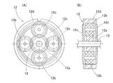
- 3A and 3B show a front view and a longitudinal sectional view of the planetary gear speed reducer 12 constituting the rotation limiting mechanism 4.
- the planetary gear speed reducer 12 is configured such that the sun gear 12a is an input stage, the planet carrier 12c that supports a plurality of planetary gears 12b is fixed, and the internal gear 12d is an output stage.
- the rotating shaft 13 of the planet carrier that is the output stage of the planetary gear reducer 11 of the eye passes through the axis of the sun gear 12a and is directly connected to the operation shaft 1b of the steering wheel 1 that is the final output end of the reaction force torque actuator. Yes.
- a stopper pin 14 as an engaging portion protrudes from one side of the internal gear 12d of the planetary gear speed reducer 12 constituting the rotation limiting mechanism 4 as shown in FIG.
- the stopper pin 14 comes into contact with the stopper 15 fixed to the inner wall portion of the housing 9, the rotatable angle range of the operation shaft 1 b of the steering wheel 1 is limited to a predetermined angle.
- the rotation limiting mechanism 4 it is possible to arbitrarily limit the rotation angle of the operation shaft 1b by changing the reduction ratio of the planetary gear speed reducer 12.
- the rotation of the internal gear 12d decelerated with respect to the rotation of the rotation shaft of the sun gear 12a as the input stage is used to limit the rotation of the operation shaft 1b. Yes.
- the planetary carrier 12c of the planetary gear speed reducer 12 is fixed and the output of the internal gear 12d is used for rotation limitation.
- the internal gear 12d is fixed and the output of the planetary carrier 12c is rotation limited. You may use for.
- the rotation reduced with respect to the rotation of the input shaft is used only for limiting the rotation of the operation shaft 1b, and the rotation speed of the output shaft is defined as the rotation speed of the input shaft. It may be the same.
- the rotation of the rotary shaft 13 at the output stage of the speed reduction mechanism 3 can be transmitted as it is to the operation shaft 1b via the rotation restriction mechanism 4, and the rotation restriction mechanism 4 is interposed between the speed reduction mechanism 3 and the operation shaft 1b.
- the reaction torque that is the output of the motor 2 can be transmitted to the operation shaft 1b by the reduction ratio of the speed reduction mechanism 3.
- the rotation limiting mechanism 4 is disposed on the output side of the speed reduction mechanism 3, but the present invention is not limited to this, and may be disposed on the input side of the speed reduction mechanism 3.
- the torque damper 5 is configured by sealing a viscous fluid 17 in a space inside the housing 9 that is sealed with an oil seal 16 and through which the operation shaft 1b of the steering wheel 1 passes.
- a viscous fluid 17 for example, silicon grease is enclosed as the viscous fluid 17 in this case, but silicon oil or silicon gel may be used as the viscous fluid 17.
- the outer diameter portion of the housing penetration portion of the operation shaft 1b is formed in a gear-cut shape as shown in FIG. 4 as a sectional view taken along line IV-IV in FIG. By setting it as this gear cutting shape, the frictional resistance between the operating shaft 1b and the viscous fluid 17 increases, and a damper effect can be raised.
- the gear cutting shape may be any shape as long as it increases the frictional resistance, such as a gear shape or a spline, serration or spiral.
- gear cutting is performed on the operation shaft 1b side, but the same effect can be obtained even if gear cutting is performed on the inner wall surface of the housing 9.
- the motor 2 is provided with two systems of steering angle sensors 18 and 19 for detecting the rotation angle of the operation shaft 1b of the steering wheel 1.
- These steering angle sensors 18, 19 are configured to detect the rotation angle of the rotation shaft 6 of the motor 2, but the rotation of the rotation shaft 6 of the motor 2 is steered at a predetermined reduction ratio set by the reduction mechanism 3. Since it is transmitted to the operation shaft 1 b of the wheel 1, the steering angle can be determined from the rotation angle of the rotation shaft 6 of the motor 2 detected by the steering angle sensors 18 and 19.
- the steering angle detected by the steering angle sensors 18 and 19 is input to an ECU (electric control unit) 20 that controls the entire steer-by-wire steering device, and the ECU 20 generates a steering reaction force according to the detected steering angle.
- the ECU 20 includes a microcomputer and an electronic circuit including a control program for the microcomputer.
- the failure mode can be detected by comparing these detected values with each other. Is possible.
- the ECU 20 controls the output of the motor 2 in accordance with the steering angle detected by the steering angle sensors 18 and 19.
- the output of the motor 2 is transmitted to the operation shaft 1b of the steering wheel 1 as a reaction torque with a predetermined reduction ratio through the speed reduction mechanism 3.
- a steering reaction force corresponding to the steering angle is generated in the steering wheel 1. Since the output of the motor 2 is transmitted to the operation shaft 1b of the steering wheel 1 by the reduction ratio of the speed reduction mechanism 3, even if a small motor 2 is used, a sufficiently large steering reaction force can be generated in the steering wheel.
- the motor 2, the speed reduction mechanism 3, the rotation limiting mechanism 4 and the torque damper 5 are arranged on the same axis as the operation shaft 1b of the steering wheel 1 and are connected in the arrangement order. Combined with the miniaturization of the motor 2, the entire apparatus can be miniaturized and lightened.
- the torque damper 5 is provided at the final output stage of the reaction force torque actuator so as to reduce the variation of the reaction force torque transmitted to the operation shaft 1 b of the steering wheel 1, the cogging of the motor 2 and the reduction mechanism 3 By reducing the vibration due to the gear noise, it is possible to prevent the steering feeling at the steering wheel 1 from being lowered and to realize a steering feeling without a sense of incongruity.
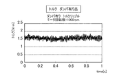
- 5 and 6 show the torque ripple of the reaction torque transmitted from the motor 2 to the operation shaft 1b of the steering wheel 1 in the reaction force torque actuator of this embodiment, with and without the torque damper 5 being omitted. It is the graph which compared and showed. In the graph of FIG. 6 showing the case where the torque damper 5 is not omitted, the torque ripple is reduced by about 50% compared to the graph of FIG. 5 showing the case where the torque damper 5 is omitted. That is, it can be seen that the torque damper 5 is highly effective in reducing the reaction force torque fluctuation.
Landscapes
- Engineering & Computer Science (AREA)
- Chemical & Material Sciences (AREA)
- Combustion & Propulsion (AREA)
- Transportation (AREA)
- Mechanical Engineering (AREA)
- Power Steering Mechanism (AREA)
Abstract
小型化および軽量化が可能で、違和感のない操舵フィーリングを実現できるステアバイワイヤ式操舵装置の反力トルクアクチュエータを提供する。この反力トルクアクチュエータは、転舵用の操舵軸と機械的に連結されていないステアリングホイールで操舵を行うようにしたステアバイワイヤ式操舵装置であって、ステアリングホイールに操舵反力を発生させるものである。操舵反力の発生源であるモータ(2)と、このモータ(2)の出力を反力トルクとしてステアリングホイール(1)の操作軸(1b)に伝達する減速機構(3)と、操作軸(1b)に伝達される反力トルクの変動を低減するトルクダンパ(5)とを備える。モータ(2)、減速機構(3)およびトルクダンパ(5)を操作軸(1b)と同一軸心上に配置して配置順に連結する。
Description
本出願は、2010年8月6日出願の特願2010-177307の優先権を主張するものであり、その全体を参照により本願の一部をなすものとして引用する。
この発明は、転舵用の操舵軸と機械的に連結されていないステアリングホイールで操舵を行うようにしたステアバイワイヤ式操舵装置の反力トルクアクチュエータに関する。
ステアバイワイヤ式操舵装置では、ステアリングホイールを操作する運連者が適度な手応えを感じるように、ステアリングホイールの操作軸の回転動作に対して反力トルク(ステアリングホイールの回転方向と逆方向に作用するトルク)を発生させる反力トルクアクチュエータが設けられる。
このような反力トルクアクチュエータとして、モータ直結型のもの(例えば特許文献1)や、複数軸に歯車を配置した減速機構を使用したもの(例えば特許文献2)や、サイクロイド減速機構を用いたもの(例えば特許文献3)などが提案されている。
特許文献1に開示されているモータ直結型の反力トルクアクチュエータは、その反力発生源であるモータをステアリングホイールの操作軸に直結させたものであるが、ステアバイワイヤ式でない操舵装置の場合と同様の操舵反力を発生させるためには、高コストで大型なモータを使用しなければならないという課題がある。
反力トルクアクチュエータにおいては、高回転は必要とせず高トルクが得られれば十分であるため、特許文献2に開示の反力トルクアクチュエータのように、反力発生源であるモータからステアリングホイールの操作軸へのトルク伝達に減速機構を使用することが有効である。しかし、特許文献2に開示の反力トルクアクチュエータでは、歯車を複数軸に配した減速機構を使用しているため、アクチュエータが大型化してしまい、ステアバイワイヤ式操舵装置における操舵機構の占めるスペースが増大するという課題がある。
これに対して、特許文献3に開示の反力トルクアクチュエータでは、減速機構としてサイクロイド減速機構を用いているので省スペース化が可能である。しかし、この場合、減速機構のギヤノイズやバックラッシによる振動、およびモータコギングが減速機構を介して増幅されてしまい、結果として操舵フィーリングの低下を招くといった課題が残る。なお、モータのコギングトルクの変動による操舵フィーリングの低下を低減するために、特許文献1に開示の反力トルクアクチュエータのように、トルクダンパが付与されたものもある。
この発明の目的は、小型化および軽量化が可能で、かつ違和感のない操舵フィーリングを実現できるステアバイワイヤ式操舵装置の反力トルクアクチュエータを提供することである。
この発明のステアバイワイヤ式操舵装置における反力トルクアクチュエータは、転舵用の操舵軸と機械的に連結されていないステアリングホイールで操舵を行い、前記ステアリングホイールに操舵反力を発生させる反力トルクアクチュエータであって、操舵反力の発生源であるモータと、このモータの出力を反力トルクとして前記ステアリングホイールの操作軸に伝達する減速機構と、前記操作軸に伝達される反力トルクの変動を低減するトルクダンパとを備え、前記モータ、減速機構、およびトルクダンパを、前記操作軸と同一軸心上に配置して配置順に連結したものである。
この構成の反力トルクアクチュエータによると、モータの出力を減速機構を経て所定の減速比で反力トルクとしてステアリングホイールの操作軸に伝達することで、ステアリングホイールに、その操舵角に応じた操舵反力を発生させる。モータの出力は減速機構の減速比でステアリングホイールの操作軸に伝達されるので、モータとして小型のものを用いてもステアリングホイールに十分大きい操舵反力を発生させることができる。
特に、この反力トルクアクチュエータでは、モータ、減速機構およびトルクダンパを、ステアリングホイールの操作軸と同一軸心上に配置順に配置して連結しているので、モータの小型化と相まって、装置全体の小型化および軽量化が可能である。また、トルクダンパを設けて、ステアリングホイールの操作軸に伝達される反力トルクの変動を低減するようにしたので、モータのコギングと減速機構のギヤノイズによる振動を低減して、ステアリングホイールでの操舵フィーリングの低下を防止でき、違和感のない操舵フィーリングを実現できる。
この発明において、前記減速機構は、遊星歯車減速機、波動歯車減速機、および遊星ローラ減速機のうちのいずれかからなるものであっても良い。これら遊星歯車減速機、波動歯車減速機、および遊星ローラ減速機であると、いずれも大きな減速比が得られ、より一層の小型化が図れる。
この発明において、前記ステアリングホイールの操作軸の回転可能な回転角の範囲を制限する回転制限機構を、前記操作軸と同一軸心上に設けても良い。ステアリングホイールの回転制限機構についても、操作軸と同一軸心上に設けることで、より一層の小型化が図れる。
前記回転制限機構が遊星歯車減速機からなり、前記操作軸から回転が入力される入力軸の回転に対して減速される回転部分で前記操作軸の回転制限を行うものとしても良い。
この場合に、前記回転制限機構は、前記入力軸の回転に対して減速した回転を前記操作軸の回転制限のみに用い、出力軸の回転数が入力軸の回転数と同一となる構造としても良い。減速した回転を回転制限のみに用い、また出力軸の回転数が入力軸の回転数と同一となる構造であると、出力軸と入力軸に一体の軸を用いることができる。これにより、回転制限機構を操作軸と同一軸心上に設けることが容易となる。
この発明において、前記トルクダンパは、オイルシールで密閉され前記ステアリングホイールの操作軸が貫通するハウジングの空間内に、粘性流体を封入したものであっても良い。この場合に、前記粘性流体が、シリコングリス、シリコンオイル、およびシリコンゲルのうちのいずれかであっても良い。粘性流体を用いたトルクダンパであると、モータのコギングと減速機構のギヤノイズによる振動の低減の効果に優れ、ステアリングホイールでの操舵フィーリングの低下をより効果的に防止することができる。
また、前記トルクダンパの構造において、前記操作軸の前記ハウジング貫通部の外径部分、または前記ハウジングの内壁部を歯切り形状としても良い。なお、この明細書で「歯切り形状」とは、表面が複数並ぶ歯部に分割された形状を言う。この場合、操作軸と粘性流体との間の摩擦抵抗、または粘性流体とハウジング内壁部との間の摩擦抵抗が増大するので、それだけトルクダンパのダンパ効果を向上させることができる。
この発明において、前記ステアリングホイールの操作軸の回転角度を検出する操舵角センサを設けても良い。この場合に、前記操舵角センサを2系統以上設け、各操舵角センサの検出値を相互に比較することで故障モードの検出を可能としても良い。
この発明において、前記モータ、減速機構、およびトルクダンパが、密閉されたハウジングで覆われていても良い。
請求の範囲および/または明細書および/または図面に開示された少なくとも2つの構成のどのような組合せも、本発明に含まれる。特に、請求の範囲の各請求項の2つ以上のどのような組合せも、本発明に含まれる。
この発明は、添付の図面を参考にした以下の好適な実施形態の説明から、より明瞭に理解されるであろう。しかしながら、実施形態および図面は単なる図示および説明のためのものであり、この発明の範囲を定めるために利用されるべきものではない。この発明の範囲は添付の請求の範囲によって定まる。添付図面において、複数の図面における同一の符号は、同一または相当する部分を示す。
この発明の一実施形態にかかるステアバイワイヤ式操舵装置の反力トルクアクチュエータの概略構成を示す縦断面図である。
同反力トルクアクチュエータの外観斜視図である
(A)は同反力トルクアクチュエータにおける減速機の正面図、(B)は同縦断面図である。
図1におけるIV-IV線断面図である。
同反力トルクアクチュエータにおけるトルクダンパを省略した場合の反力トルクの変動を示すグラフである。
同反力トルクアクチュエータにおけるトルクダンパを省略しない場合の反力トルクの変動を示すグラフである。
この発明の一実施形態を図1ないし図6と共に説明する。図1はこの実施形態の反力トルクアクチュエータの概略図を示し、図2はその外観斜視図を示す。この反力トルクアクチュエータは、転舵用の操舵軸(図示せず)と機械的に連結されていないステアリングホイール1で操舵を行うようにしたステアバイワイヤ式操舵装置において、ステアリングホイール1に操舵反力を発生させる装置である。ステアリングホイール1は、運転者が回転操作するハンドル1aと、その回転中心に位置してハンドル1aと一体に回転する操作軸1bとでなる。操作軸1bは4つのハウジング片9a~9dを軸方向に並べて連結してなる密閉されたハウジング9に挿入され、軸受21,22を介して第1ハウジング片9aに回転自在に支持されている。この反力トルクアクチュエータは、操舵反力の発生源であるモータ2と、このモータ2の出力を反力トルクとしてステアリングホイール1の操作軸1bに伝達する減速機構3と、ステアリングホイール1の操作軸1bの回転を制限する回転制限機構4と、前記操作軸1bに伝達される反力トルクの変動を低減するトルクダンパ5とを備える。
前記モータ2、減速機構3、回転制限機構4およびトルクダンパ5は、ステアリングホイール1の操作軸1bと同一軸心上でこの配列順序に並べられて連結され、密閉された前記ハウジング9で覆われている。すなわち、モータ2は、その回転軸6がステアリングホイール1の操作軸1bと同一軸心上に並ぶように、操作軸1bの軸方向延長上に配置されて第4ハウジング片9dで覆われ、回転軸6が軸受7,8を介して前記第4ハウジング片9dに支持されている。また、減速機構3は筒状の第3ハウジング片9cで、回転制限機構4は筒状の第2ハウジング片9bでそれぞれ覆われている。トルクダンパ5は操作軸1bと同様、筒状の第1ハウジング片9aで覆われている。
減速機構3は、2つの遊星歯車減速機10,11を備える2段の遊星歯車減速機からなり、これもその回転中心が操作軸1bと同一軸心となるように、モータ2の出力側に配置される。これら2段の遊星歯車減速機10,11は、いずれも、サンギヤが入力段、インターナルギヤが固定、遊星キャリアが出力段となるように構成されており、1段目の遊星歯車減速機10の入力段であるサンギヤの軸心にモータ2の回転軸6が連結される。このように、減速機構3を2段の遊星歯車減速機10,11で構成することにより、最適な減速比に設定することができる。なお、最適な減速比が設定できれば、遊星歯車減速機の段数は1段でも多段でも良い。減速機構3を遊星歯車減速機10,11で構成する代わりに、波動歯車減速機や遊星ローラ減速機で構成しても良い。
回転制限機構4は遊星歯車減速機12からなり、減速機構3の出力側、つまり減速機構3の2段目の遊星歯車減速機12に隣接して、操作軸1bと同一軸心となるように配置される。図3(A),(B)は、回転制限機構4を構成する遊星歯車減速機12の正面図および縦断面図を示す。この遊星歯車減速機12では、サンギヤ12aが入力段、複数の遊星ギヤ12bを支持する遊星キャリア12cが固定、インターナルギヤ12dが出力段となるように構成されており、減速機構3における2段目の遊星歯車減速機11の出力段となる遊星キャリアの回転軸13がサンギヤ12aの軸心を貫通して、反力トルクアクチュエータの最終出力端となるステアリングホイール1の操作軸1bに直結されている。
回転制限機構4を構成する遊星歯車減速機12のインターナルギヤ12dの片面には、図1のように係合部であるストッパピン14が突設されている。このストッパピン14がハウジング9の内壁部に固定されたストッパ15に当接することで、ステアリングホイール1の操作軸1bの回転可能な角度範囲が所定角度に制限される。
この回転制限機構4では、遊星歯車減速機12の減速比を変更することにより、操作軸1bの回転角を任意に制限することが可能となる。ここでは、入力段であるサンギヤ12aの回転軸(減速機構3における出力段の回転軸13に等しい)の回転に対して減速したインターナルギヤ12dの回転が操作軸1bの回転制限に用いられている。
なお、ここでは、遊星歯車減速機12の遊星キャリア12cを固定し、インターナルギヤ12dの出力を回転制限に用いているが、インターナルギヤ12dを固定して、遊星キャリア12cの出力を回転制限に用いても良い。このほか、回転制限機構4を構成する遊星歯車減速機において、その入力軸の回転に対して減速した回転を操作軸1bの回転制限にのみ用い、出力軸の回転数を入力軸の回転数と同一にしても良い。この場合、減速機構3の出力段の回転軸13の回転を、回転制限機構4を経てそのまま操作軸1bに伝達でき、減速機構3と操作軸1bとの間に回転制限機構4が介在しても、モータ2の出力である反力トルクを減速機構3の減速比で操作軸1bに伝達できる。また、ここでは、回転制限機構4を減速機構3の出力側に配置しているが、これに限らず減速機構3の入力側に配置しても良い。
トルクダンパ5は、ハウジング9内において、オイルシール16で密閉されステアリングホイール1の操作軸1bが貫通する空間に粘性流体17を封入して構成される。この場合の粘性流体17として例えばシリコングリスが封入されるが、粘性流体17として、そのほかシリコンオイルやシリコンゲルを使用しても良い。操作軸1bの前記ハウジング貫通部の外径部分は、図4に図1におけるIV-IV線断面図として示すように歯切り形状とされている。この歯切り形状とすることで、操作軸1bと粘性流体17の間の摩擦抵抗が増大して、ダンパ効果を上げることができる。歯切り形状は、歯車状の形状や、スプライン、セレーション、スパイラルなど、摩擦抵抗を増大させる形状であれば何れの形状でも良い。なお、この実施形態では、操作軸1b側に歯切り加工を行っているが、ハウジング9の内壁面に歯切り加工を行っても同様の効果を得ることができる。
また、モータ2には、ステアリングホイール1の操作軸1bの回転角度を検出する2系統の操舵角センサ18,19が設けられている。これらの操舵角センサ18,19はモータ2の回転軸6の回転角度を検出する構成となっているが、モータ2の回転軸6の回転は減速機構3で設定される所定の減速比でステアリングホイール1の操作軸1bに伝達されるので、操舵角センサ18,19が検出するモータ2の回転軸6の回転角度から、操舵角を割り出すことができる。操舵角センサ18,19によって検出された操舵角は、ステアバイワイヤ式操舵装置の全体を制御するECU(電気制御ユニット)20に入力され、ECU20は検出された操舵角に応じた操舵反力を発生するようにモータ2の出力を制御する。ECU20は、マイクロコンピュータおよびその制御プログラムを含む電子回路等により構成される。
この実施形態では、ステアリングホイール1の操作軸1bの回転角度を検出する2系統の操舵角センサ18,19が設けられているので、これらの検出値を相互に比較することにより故障モードの検出が可能である。
この構成の反力トルクアクチュエータによると、操舵角センサ18,19の検出する操舵角に応じてECU20がモータ2の出力を制御する。モータ2の出力は減速機構3を経て所定の減速比で反力トルクとしてステアリングホイール1の操作軸1bに伝達される。これにより、ステアリングホイール1には、その操舵角に応じた操舵反力が発生する。モータ2の出力は減速機構3の減速比でステアリングホイール1の操作軸1bに伝達されるので、モータ2として小型のものを用いてもステアリングホイールに十分大きい操舵反力を発生させることができる。
特に、この反力トルクアクチュエータでは、モータ2、減速機構3、回転制限機構4およびトルクダンパ5を、ステアリグホイール1の操作軸1bと同一軸心上に配置してその配置順に連結しているので、モータ2の小型化と相まって、装置全体の小型化および軽量化が可能である。また、トルクダンパ5を反力トルクアクチュエータの最終出力段に設けて、ステアリングホイール1の操作軸1bに伝達される反力トルクの変動を低減するようにしているので、モータ2のコギングと減速機構3のギヤノイズによる振動を低減して、ステアリングホイール1での操舵フィーリングの低下を防止でき、違和感のない操舵フィーリングを実現できる。
図5および図6は、この実施形態の反力トルクアクチュエータにおいて、トルクダンパ5を省略した場合と省略しない場合とで、モータ2からステアリングホイール1の操作軸1bに伝達される反力トルクのトルクリップルを比較して示したグラフである。トルクダンパ5を省略しない場合を示す図6のグラフでは、トルクダンパ5を省略した場合を示す図5のグラフに比べて、およそ50%程度トルクリップルが低減している。つまり、トルクダンパ5による反力トルクの変動低減効果が高いことが分かる。
以上のとおり、図面を参照しながら好適な実施形態を説明したが、当業者であれば、本件明細書を見て、自明な範囲内で種々の変更および修正を容易に想定するであろう。したがって、そのような変更および修正は、請求の範囲から定まる発明の範囲内のものと解釈される。
1…ステアリングホイール
1b…ステアリングホイールの操作軸
2…モータ
3…減速機構
4…回転制限機構
5…トルクダンパ
9…ハウジング
10,11…減速機構の遊星歯車減速機
12…回転制限機構の遊星歯車減速機
14…ストッパピン
15…ストッパ
17…粘性流体
18,19…操舵角センサ
1b…ステアリングホイールの操作軸
2…モータ
3…減速機構
4…回転制限機構
5…トルクダンパ
9…ハウジング
10,11…減速機構の遊星歯車減速機
12…回転制限機構の遊星歯車減速機
14…ストッパピン
15…ストッパ
17…粘性流体
18,19…操舵角センサ
Claims (11)
- 転舵用の操舵軸と機械的に連結されていないステアリングホイールで操舵を行い、前記ステアリングホイールに操舵反力を発生させるステアバイワイヤ式操舵装置における反力トルクアクチュエータであって、
操舵反力の発生源であるモータと、
このモータの出力を反力トルクとして前記ステアリングホイールの操作軸に伝達する減速機構と、
前記操作軸に伝達される反力トルクの変動を低減するトルクダンパとを備え、
前記モータ、減速機構、およびトルクダンパを、前記操作軸と同一軸心上に配置して配置順に連結したステアバイワイヤ式操舵装置の反力トルクアクチュエータ。 - 請求項1において、前記減速機構が、遊星歯車減速機、波動歯車減速機、および遊星ローラ減速機のうちのいずれかからなるステアバイワイヤ式操舵装置の反力トルクアクチュエータ。
- 請求項1において、前記ステアリングホイールの操作軸の回転可能な回転角の範囲を制限する回転制限機構を、前記操作軸と同一軸心上に設けたステアバイワイヤ式操舵装置の反力トルクアクチュエータ。
- 請求項3において、前記回転制限機構が遊星歯車減速機からなり、前記操作軸から回転が入力される入力軸の回転に対して減速される回転部分で前記操作軸の回転制限を行うものとしたステアバイワイヤ式操舵装置の反力トルクアクチュエータ。
- 請求項4において、前記回転制限機構は、前記入力軸の回転に対して減速した回転を前記操作軸の回転制限のみに用い、出力軸の回転数が入力軸の回転数と同一となる構造であるステアバイワイヤ式操舵装置の反力トルクアクチュエータ。
- 請求項1において、前記トルクダンパは、オイルシールで密閉され前記ステアリングホイールの操作軸が貫通するハウジングの空間内に、粘性流体を封入したものであるステアバイワイヤ式操舵装置の反力トルクアクチュエータ。
- 請求項6において、前記粘性流体が、シリコングリス、シリコンオイル、およびシリコンゲルのうちのいずれかであるステアバイワイヤ式操舵装置の反力トルクアクチュエータ。
- 請求項6において、前記操作軸の前記ハウジング貫通部の外径部分、または前記ハウジングの内壁部を歯切り形状としたステアバイワイヤ式操舵装置の反力トルクアクチュエータ。
- 請求項1において、前記ステアリングホイールの操作軸の回転角度を検出する操舵角センサを設けたステアバイワイヤ式操舵装置の反力トルクアクチュエータ。
- 請求項9において、前記操舵角センサを2系統以上設け、各操舵角センサの検出値を相互に比較することで故障モードの検出を可能としたステアバイワイヤ式操舵装置の反力トルクアクチュエータ。
- 請求項1において、前記モータ、減速機構、およびトルクダンパが、密閉されたハウジングで覆われているステアバイワイヤ式操舵装置の反力トルクアクチュエータ。
Applications Claiming Priority (2)
| Application Number | Priority Date | Filing Date | Title |
|---|---|---|---|
| JP2010177307A JP5675207B2 (ja) | 2010-08-06 | 2010-08-06 | ステアバイワイヤ式操舵装置の反力トルクアクチュエータ |
| JP2010-177307 | 2010-08-06 |
Publications (1)
| Publication Number | Publication Date |
|---|---|
| WO2012017886A1 true WO2012017886A1 (ja) | 2012-02-09 |
Family
ID=45559387
Family Applications (1)
| Application Number | Title | Priority Date | Filing Date |
|---|---|---|---|
| PCT/JP2011/067054 Ceased WO2012017886A1 (ja) | 2010-08-06 | 2011-07-27 | ステアバイワイヤ式操舵装置の反力トルクアクチュエータ |
Country Status (2)
| Country | Link |
|---|---|
| JP (1) | JP5675207B2 (ja) |
| WO (1) | WO2012017886A1 (ja) |
Cited By (8)
| Publication number | Priority date | Publication date | Assignee | Title |
|---|---|---|---|---|
| EP3064413A1 (en) * | 2015-03-05 | 2016-09-07 | Showa Corporation | Reaction force actuator and steering device |
| WO2017009125A1 (de) * | 2015-07-15 | 2017-01-19 | Thyssenkrupp Presta Ag | Feedback-aktuator für eine lenkeinrichtung |
| DE102017008672A1 (de) | 2017-09-14 | 2018-06-07 | Daimler Ag | Dynamischer Anschlag für ein Steer-by-wire Lenksystem |
| WO2020184857A1 (ko) * | 2019-03-08 | 2020-09-17 | 주식회사 만도 | 스티어 바이 와이어식 조향장치 |
| WO2022049249A1 (de) * | 2020-09-07 | 2022-03-10 | Thyssenkrupp Presta Ag | Feedback-aktuator für ein lenksystem |
| CN116788350A (zh) * | 2023-07-21 | 2023-09-22 | 浙江极氪智能科技有限公司 | 一种新型线控转向管柱手感模拟器 |
| WO2024251395A1 (de) * | 2023-06-08 | 2024-12-12 | Volkswagen Aktiengesellschaft | Ringförmiges dichtungssystem zur abdichtung von verbindungsstellen innerhalb eines steer-by-wire lenksystems eines kraftfahrzeugs |
| DE102024136604A1 (de) * | 2024-11-29 | 2026-06-03 | Schaeffler Technologies AG & Co. KG | Bedienvorrichtung mit einer Rückmeldungseinheit |
Families Citing this family (5)
| Publication number | Priority date | Publication date | Assignee | Title |
|---|---|---|---|---|
| KR102238980B1 (ko) * | 2017-03-16 | 2021-04-13 | 현대모비스 주식회사 | 스티어 바이 와이어 장치 |
| DE102017207272A1 (de) * | 2017-04-28 | 2018-10-31 | Volkswagen Aktiengesellschaft | Lenkungshandhabe |
| US11124220B2 (en) | 2017-12-19 | 2021-09-21 | Mando Corporation | Steer-by-wire type steering apparatus |
| KR102548805B1 (ko) * | 2018-04-04 | 2023-06-29 | 에이치엘만도 주식회사 | 스티어 바이 와이어식 조향장치 |
| KR102167450B1 (ko) * | 2019-03-14 | 2020-10-19 | 주식회사 만도 | 스티어 바이 와이어용 조향장치 |
Citations (7)
| Publication number | Priority date | Publication date | Assignee | Title |
|---|---|---|---|---|
| JPH02175465A (ja) * | 1988-12-28 | 1990-07-06 | Honda Motor Co Ltd | 車両用操舵機構 |
| JP2002166839A (ja) * | 2000-11-22 | 2002-06-11 | Visteon Global Technologies Inc | 磁性−レオロジー疑似操舵感装置 |
| JP2004175257A (ja) * | 2002-11-28 | 2004-06-24 | Toyota Motor Corp | 車両の操舵装置 |
| JP2005324774A (ja) * | 2004-04-12 | 2005-11-24 | Toyota Motor Corp | ダンピングフォース発生装置およびそれを備えたステアリングシステム |
| JP2006188081A (ja) * | 2004-12-28 | 2006-07-20 | Toyota Motor Corp | 車両用ステアリングシステム |
| JP2008126685A (ja) * | 2006-11-16 | 2008-06-05 | Nsk Ltd | 操舵装置 |
| JP2010052672A (ja) * | 2008-08-29 | 2010-03-11 | Toyota Motor Corp | 車両の操舵装置 |
Family Cites Families (4)
| Publication number | Priority date | Publication date | Assignee | Title |
|---|---|---|---|---|
| JPH0187334U (ja) * | 1987-12-02 | 1989-06-09 | ||
| JPH10211885A (ja) * | 1997-01-30 | 1998-08-11 | Koyo Seiko Co Ltd | 自動車の舵取装置 |
| JP2004322808A (ja) * | 2003-04-24 | 2004-11-18 | Honda Motor Co Ltd | ステア・バイ・ワイヤ式操舵装置 |
| JP2007245819A (ja) * | 2006-03-14 | 2007-09-27 | Nsk Ltd | ステアバイワイヤシステムの入力装置 |
-
2010
- 2010-08-06 JP JP2010177307A patent/JP5675207B2/ja active Active
-
2011
- 2011-07-27 WO PCT/JP2011/067054 patent/WO2012017886A1/ja not_active Ceased
Patent Citations (7)
| Publication number | Priority date | Publication date | Assignee | Title |
|---|---|---|---|---|
| JPH02175465A (ja) * | 1988-12-28 | 1990-07-06 | Honda Motor Co Ltd | 車両用操舵機構 |
| JP2002166839A (ja) * | 2000-11-22 | 2002-06-11 | Visteon Global Technologies Inc | 磁性−レオロジー疑似操舵感装置 |
| JP2004175257A (ja) * | 2002-11-28 | 2004-06-24 | Toyota Motor Corp | 車両の操舵装置 |
| JP2005324774A (ja) * | 2004-04-12 | 2005-11-24 | Toyota Motor Corp | ダンピングフォース発生装置およびそれを備えたステアリングシステム |
| JP2006188081A (ja) * | 2004-12-28 | 2006-07-20 | Toyota Motor Corp | 車両用ステアリングシステム |
| JP2008126685A (ja) * | 2006-11-16 | 2008-06-05 | Nsk Ltd | 操舵装置 |
| JP2010052672A (ja) * | 2008-08-29 | 2010-03-11 | Toyota Motor Corp | 車両の操舵装置 |
Cited By (11)
| Publication number | Priority date | Publication date | Assignee | Title |
|---|---|---|---|---|
| EP3064413A1 (en) * | 2015-03-05 | 2016-09-07 | Showa Corporation | Reaction force actuator and steering device |
| CN105936292A (zh) * | 2015-03-05 | 2016-09-14 | 株式会社昭和 | 反作用力致动器和转向装置 |
| US9683639B2 (en) | 2015-03-05 | 2017-06-20 | Showa Corporation | Reaction force actuator and steering device |
| WO2017009125A1 (de) * | 2015-07-15 | 2017-01-19 | Thyssenkrupp Presta Ag | Feedback-aktuator für eine lenkeinrichtung |
| DE102017008672A1 (de) | 2017-09-14 | 2018-06-07 | Daimler Ag | Dynamischer Anschlag für ein Steer-by-wire Lenksystem |
| WO2020184857A1 (ko) * | 2019-03-08 | 2020-09-17 | 주식회사 만도 | 스티어 바이 와이어식 조향장치 |
| US12208842B2 (en) | 2019-03-08 | 2025-01-28 | Hl Mando Corporation | Steer-by-wire steering apparatus |
| WO2022049249A1 (de) * | 2020-09-07 | 2022-03-10 | Thyssenkrupp Presta Ag | Feedback-aktuator für ein lenksystem |
| WO2024251395A1 (de) * | 2023-06-08 | 2024-12-12 | Volkswagen Aktiengesellschaft | Ringförmiges dichtungssystem zur abdichtung von verbindungsstellen innerhalb eines steer-by-wire lenksystems eines kraftfahrzeugs |
| CN116788350A (zh) * | 2023-07-21 | 2023-09-22 | 浙江极氪智能科技有限公司 | 一种新型线控转向管柱手感模拟器 |
| DE102024136604A1 (de) * | 2024-11-29 | 2026-06-03 | Schaeffler Technologies AG & Co. KG | Bedienvorrichtung mit einer Rückmeldungseinheit |
Also Published As
| Publication number | Publication date |
|---|---|
| JP2012035738A (ja) | 2012-02-23 |
| JP5675207B2 (ja) | 2015-02-25 |
Similar Documents
| Publication | Publication Date | Title |
|---|---|---|
| JP5675207B2 (ja) | ステアバイワイヤ式操舵装置の反力トルクアクチュエータ | |
| KR102617234B1 (ko) | 보조 디바이스 | |
| EP2559607B1 (en) | Electric power steering device | |
| US7735597B2 (en) | Steering apparatus for vehicle | |
| JP2009061836A (ja) | 舵角可変式ステアリング装置 | |
| JP4930751B2 (ja) | ステアリング装置 | |
| JP2009132306A (ja) | 操舵装置 | |
| WO2007049444A1 (en) | Steering apparatus for vehicle | |
| WO2016203960A1 (ja) | ステアリング装置 | |
| KR20190082471A (ko) | 자결 기능을 가지는 양축 볼 감속 장치 | |
| JP2010144762A (ja) | 駆動力配分装置 | |
| EP1900969B1 (en) | Reduction Gear Mechanism and Electric Power Steering Apparatus | |
| JP5989148B2 (ja) | 減速機、及びこれを具えた直交型ギアモータ | |
| JP4871644B2 (ja) | バックラッシュ除去方法及び装置 | |
| JP3979318B2 (ja) | 車両用操舵装置 | |
| KR102111294B1 (ko) | 스티어 바이 와이어식 조향장치 | |
| JP2007245819A (ja) | ステアバイワイヤシステムの入力装置 | |
| CN112664637A (zh) | 车辆驱动装置 | |
| JP2009293789A (ja) | スタビライザ制御装置 | |
| JP2006275274A (ja) | 回転伝動装置 | |
| JP2019214232A (ja) | 車両用ステアリング装置 | |
| JP5397662B2 (ja) | 車両用操舵装置 | |
| JP2014101050A (ja) | 伝達比可変装置 | |
| JP2009132305A (ja) | 操舵装置 | |
| KR102261572B1 (ko) | 차량용 조향 장치 |
Legal Events
| Date | Code | Title | Description |
|---|---|---|---|
| 121 | Ep: the epo has been informed by wipo that ep was designated in this application |
Ref document number: 11814513 Country of ref document: EP Kind code of ref document: A1 |
|
| NENP | Non-entry into the national phase |
Ref country code: DE |
|
| 122 | Ep: pct application non-entry in european phase |
Ref document number: 11814513 Country of ref document: EP Kind code of ref document: A1 |