WO2012017764A1 - 光ファイバ - Google Patents
光ファイバ Download PDFInfo
- Publication number
- WO2012017764A1 WO2012017764A1 PCT/JP2011/065301 JP2011065301W WO2012017764A1 WO 2012017764 A1 WO2012017764 A1 WO 2012017764A1 JP 2011065301 W JP2011065301 W JP 2011065301W WO 2012017764 A1 WO2012017764 A1 WO 2012017764A1
- Authority
- WO
- WIPO (PCT)
- Prior art keywords
- optical fiber
- core
- refractive index
- holes
- core portion
- Prior art date
- Legal status (The legal status is an assumption and is not a legal conclusion. Google has not performed a legal analysis and makes no representation as to the accuracy of the status listed.)
- Ceased
Links
Images










Classifications
-
- G—PHYSICS
- G02—OPTICS
- G02B—OPTICAL ELEMENTS, SYSTEMS OR APPARATUS
- G02B6/00—Light guides; Structural details of arrangements comprising light guides and other optical elements, e.g. couplings
- G02B6/02—Optical fibres with cladding with or without a coating
- G02B6/02004—Optical fibres with cladding with or without a coating characterised by the core effective area or mode field radius
- G02B6/02009—Large effective area or mode field radius, e.g. to reduce nonlinear effects in single mode fibres
- G02B6/02014—Effective area greater than 60 square microns in the C band, i.e. 1530-1565 nm
- G02B6/02019—Effective area greater than 90 square microns in the C band, i.e. 1530-1565 nm
-
- G—PHYSICS
- G02—OPTICS
- G02B—OPTICAL ELEMENTS, SYSTEMS OR APPARATUS
- G02B6/00—Light guides; Structural details of arrangements comprising light guides and other optical elements, e.g. couplings
- G02B6/02—Optical fibres with cladding with or without a coating
- G02B6/02295—Microstructured optical fibre
- G02B6/02314—Plurality of longitudinal structures extending along optical fibre axis, e.g. holes
- G02B6/02342—Plurality of longitudinal structures extending along optical fibre axis, e.g. holes characterised by cladding features, i.e. light confining region
- G02B6/02366—Single ring of structures, e.g. "air clad"
-
- G—PHYSICS
- G02—OPTICS
- G02B—OPTICAL ELEMENTS, SYSTEMS OR APPARATUS
- G02B6/00—Light guides; Structural details of arrangements comprising light guides and other optical elements, e.g. couplings
- G02B6/02—Optical fibres with cladding with or without a coating
- G02B6/028—Optical fibres with cladding with or without a coating with core or cladding having graded refractive index
- G02B6/0281—Graded index region forming part of the central core segment, e.g. alpha profile, triangular, trapezoidal core
-
- G—PHYSICS
- G02—OPTICS
- G02B—OPTICAL ELEMENTS, SYSTEMS OR APPARATUS
- G02B6/00—Light guides; Structural details of arrangements comprising light guides and other optical elements, e.g. couplings
- G02B6/02—Optical fibres with cladding with or without a coating
- G02B6/036—Optical fibres with cladding with or without a coating core or cladding comprising multiple layers
- G02B6/03605—Highest refractive index not on central axis
- G02B6/03611—Highest index adjacent to central axis region, e.g. annular core, coaxial ring, centreline depression affecting waveguiding
-
- G—PHYSICS
- G02—OPTICS
- G02B—OPTICAL ELEMENTS, SYSTEMS OR APPARATUS
- G02B6/00—Light guides; Structural details of arrangements comprising light guides and other optical elements, e.g. couplings
- G02B6/02—Optical fibres with cladding with or without a coating
- G02B6/036—Optical fibres with cladding with or without a coating core or cladding comprising multiple layers
- G02B6/03616—Optical fibres characterised both by the number of different refractive index layers around the central core segment, i.e. around the innermost high index core layer, and their relative refractive index difference
- G02B6/03622—Optical fibres characterised both by the number of different refractive index layers around the central core segment, i.e. around the innermost high index core layer, and their relative refractive index difference having 2 layers only
- G02B6/03633—Optical fibres characterised both by the number of different refractive index layers around the central core segment, i.e. around the innermost high index core layer, and their relative refractive index difference having 2 layers only arranged - -
-
- G—PHYSICS
- G02—OPTICS
- G02B—OPTICAL ELEMENTS, SYSTEMS OR APPARATUS
- G02B6/00—Light guides; Structural details of arrangements comprising light guides and other optical elements, e.g. couplings
- G02B6/02—Optical fibres with cladding with or without a coating
- G02B6/036—Optical fibres with cladding with or without a coating core or cladding comprising multiple layers
- G02B6/03616—Optical fibres characterised both by the number of different refractive index layers around the central core segment, i.e. around the innermost high index core layer, and their relative refractive index difference
- G02B6/03638—Optical fibres characterised both by the number of different refractive index layers around the central core segment, i.e. around the innermost high index core layer, and their relative refractive index difference having 3 layers only
- G02B6/03644—Optical fibres characterised both by the number of different refractive index layers around the central core segment, i.e. around the innermost high index core layer, and their relative refractive index difference having 3 layers only arranged - + -
-
- G—PHYSICS
- G02—OPTICS
- G02B—OPTICAL ELEMENTS, SYSTEMS OR APPARATUS
- G02B6/00—Light guides; Structural details of arrangements comprising light guides and other optical elements, e.g. couplings
- G02B6/02—Optical fibres with cladding with or without a coating
- G02B6/036—Optical fibres with cladding with or without a coating core or cladding comprising multiple layers
- G02B6/03616—Optical fibres characterised both by the number of different refractive index layers around the central core segment, i.e. around the innermost high index core layer, and their relative refractive index difference
- G02B6/03638—Optical fibres characterised both by the number of different refractive index layers around the central core segment, i.e. around the innermost high index core layer, and their relative refractive index difference having 3 layers only
- G02B6/0365—Optical fibres characterised both by the number of different refractive index layers around the central core segment, i.e. around the innermost high index core layer, and their relative refractive index difference having 3 layers only arranged - - +
Definitions
- the present invention relates to an optical fiber.
- the power of light propagating through a single optical fiber has increased, and nonlinear optical phenomena and fiber fuses in optical fibers have become major problems.
- it is effective to increase the effective core area (Aeff) of the optical fiber.
- the macro bending loss and the microbend loss are increased.
- the microbend loss is defined as an increase in transmission loss due to a slight bending applied to the optical fiber when a lateral pressure is applied to the optical fiber.
- Non-Patent Document 1 proposes an optical fiber in which the effective core area is expanded to 120 ⁇ m 2 by optimizing the trench type refractive index distribution.
- Non-Patent Document 2 reports a result of expanding the effective core area to 134 ⁇ m 2 by optimizing the W-type refractive index distribution.
- Non-Patent Document 2 shows that an increase in microbend loss is the greatest barrier for further expanding the effective core area. Further, the increase in the microbend loss is not limited to the increase in the effective core area, but is a factor that limits the degree of freedom in designing the optical characteristics of the optical fiber.
- Non-Patent Document 3 shows that microbending loss can be suppressed by providing a hole structure in the fiber cross section.
- an optical fiber for example, a holey fiber: HF
- HF holey fiber
- the present invention has been made in view of the above, and an object thereof is to provide an optical fiber having high manufacturability and high degree of freedom in optical design.
- an optical fiber according to the present invention includes a core portion that confines and guides light, and a clad portion formed on an outer periphery of the core portion, and The cladding part is formed at a position spaced from the core part by a distance that does not substantially affect the effective core cross-sectional area or wavelength dispersion characteristics in the core part, and reduces the microbend loss in the core part. It is characterized by having.
- the optical fiber according to the present invention is the optical fiber according to the above-mentioned invention, wherein the effective core area or wavelength dispersion characteristic value of the optical fiber and the effective core area or wavelength dispersion when the optical fiber is free of the holes.
- the ratio between the difference between the characteristic value and the effective core area or the chromatic dispersion characteristic value when there is no hole is within ⁇ 10%, respectively.
- the optical fiber according to the present invention is characterized in that, in the above-mentioned invention, the center of the hole is separated from the center of the core part by 25 ⁇ m or more.
- the optical fiber according to the present invention is characterized in that, in the above-mentioned invention, the clad portion has 36 or less holes, and the hole diameter is 10 ⁇ m or less.
- the effective core area at a wavelength of 1550 nm is 100 ⁇ m 2 or more.
- the optical fiber according to the present invention is the optical fiber according to the above invention, wherein the core portion is located at a center core portion having a higher refractive index than the cladding portion and an outer periphery of the center core portion, and is refracted more than the cladding portion.
- a relative refractive index difference of the central core portion relative to the cladding portion is 0.1% to 0.3%
- a relative refractive index difference of the outer peripheral core portion relative to the cladding portion is -0.2% to -0.05%
- the diameter of the central core portion is 11.2 ⁇ m to 23.9 ⁇ m
- the ratio of the outer diameter of the outer peripheral core portion to the diameter of the central core portion is 2. It is 0 to 4.0.
- the core portion has a refractive index distribution of the unimodal, characterized in that the effective core area at the wavelength of 1550nm is 100 ⁇ m 2 ⁇ 185 ⁇ m 2 And
- the cladding portion has twelve or more holes arranged in a circle around the core portion, and the hole diameter is 2. It is 5 ⁇ 0.5 ⁇ m, and the center of the hole is separated from the center of the core part by 40 ⁇ m or more and is separated from the outer edge of the cladding part by 2.5 ⁇ m or more.
- a relative refractive index difference of the core portion with respect to the cladding portion is 0.16% to 0.33%, and a diameter of the core portion is 10 ⁇ m to 14 ⁇ m. It is characterized by being.
- the microbend loss of the optical fiber at a wavelength of 1550 nm is 80% or less of the microbend loss in the case where the optical fiber does not have the holes. It is characterized by.
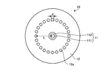
- FIG. 1 is a schematic cross-sectional view of an optical fiber according to the first embodiment.
- FIG. 2 is a diagram showing a refractive index distribution in the vicinity of the core portion of the optical fiber shown in FIG.
- FIG. 3 is a diagram showing design parameters and optical characteristics of a W-type refractive index distribution set so that the cutoff wavelength is 1500 nm.
- FIG. 4 is a diagram showing design parameters and optical characteristics of a W-type refractive index distribution set so that the cutoff wavelength is 1500 nm.
- FIG. 5 is a diagram showing design parameters and optical characteristics of a W-type refractive index distribution set so that the cutoff wavelength is 1500 nm.
- FIG. 1 is a schematic cross-sectional view of an optical fiber according to the first embodiment.
- FIG. 2 is a diagram showing a refractive index distribution in the vicinity of the core portion of the optical fiber shown in FIG.
- FIG. 3 is a diagram showing design parameters and optical characteristics of a W-type refractive index distribution set
- FIG. 6 is a diagram showing design parameters and optical characteristics of a W-type refractive index distribution set so that the cutoff wavelength is 1500 nm.
- FIG. 7 is a diagram showing design parameters and optical characteristics of a W-type refractive index distribution set so that the cutoff wavelength is 1400 nm.
- FIG. 8 is a diagram showing design parameters and optical characteristics of a W-type refractive index distribution set so that the cutoff wavelength is 1300 nm.
- FIG. 9 is a schematic cross-sectional view of a clad portion in which 12, 18, or 24 holes are arranged.
- FIG. 10 is a diagram showing design parameters and optical characteristics of a clad portion having only a hole without having a core portion.
- FIG. 11 is a diagram showing design parameters and optical characteristics of the W-type refractive index distribution selected from FIGS.
- FIG. 12 is a diagram showing design parameters and optical characteristics of the hole structure selected from FIG.
- FIG. 13 is a diagram showing design parameters of an optical fiber configured by combining the W-type refractive index distribution and the hole structure shown in FIGS.
- FIG. 14 is a diagram showing optical characteristics of the optical fiber having the design parameters shown in FIG.
- FIG. 15 is a schematic cross-sectional view of an optical fiber according to the second embodiment.
- FIG. 16 is a view showing a refractive index distribution in the vicinity of the core portion of the optical fiber shown in FIG. FIG.
- FIG. 17 is a diagram showing design parameters, a cross-sectional structure, and optical characteristics of an optical fiber having a single-peak type refractive index distribution but having no holes, and an optical fiber configured by combining this with a hole structure. It is.
- FIG. 18 is a diagram illustrating optical characteristics of optical fibers of Examples and Comparative Examples.
- FIG. 19 is a diagram illustrating the wavelength dependence of the microbend loss of the optical fibers of the example and the comparative example.
- FIG. 20 is a schematic cross-sectional view of an optical fiber according to a modification of the second embodiment.
- FIG. 21 is a diagram for explaining an example of a method for manufacturing an optical fiber according to the present invention.
- FIG. 22 is a diagram illustrating a refractive index profile that can be used in the present invention.
- the cutoff wavelength is ITU-T (International Telecommunication Union) G. unless otherwise specified. It means the fiber cutoff wavelength defined by 650.1.
- the bending loss means a macro bending loss at a diameter of 20 mm.
- ITU-TG International Telecommunication Union
- FIG. 1 is a schematic cross-sectional view of an optical fiber according to Embodiment 1 of the present invention.
- the optical fiber 10 includes a core part 11 located at the center and a clad part 12 located on the outer periphery of the core part 11.
- the core part 11 includes a central core part 111 and an outer peripheral core part 112 located on the outer periphery of the central core part 111.
- the clad portion 12 is formed at a position separated from the core portion 11 by a predetermined distance, and has 24 holes 12a arranged in a circle at an equal angle with the core portion 11 as the center.
- the number of holes is an example, and is not limited to 24.
- the central core 111 is made of quartz glass containing a dopant that increases the refractive index, such as germanium (Ge).
- the outer core portion 112 is made of quartz glass containing a dopant that lowers the refractive index, such as fluorine (F).
- the clad portion 12 is made of pure quartz glass that does not contain a dopant that adjusts the refractive index. As a result, the central core portion 111 has a higher refractive index than the clad portion 12, and the outer peripheral core portion 112 has a lower refractive index than the clad portion 12.
- FIG. 2 is a diagram showing a refractive index distribution in the vicinity of the core portion 11 of the optical fiber shown in FIG.
- the distribution profile P ⁇ b> 1 indicates the refractive index distribution of the central core portion 111.
- a distribution profile P ⁇ b> 2 indicates the refractive index distribution of the outer peripheral core portion 112.
- the distribution profile P3 indicates the refractive index distribution of the cladding part 12.
- the optical fiber 10 has a so-called W-type refractive index distribution in which the refractive index of the outer core portion 112 is lower than the refractive index of the cladding portion 12.
- FIG. 1 indicates the refractive index distribution of the central core portion 111.
- a distribution profile P ⁇ b> 2 indicates the refractive index distribution of the outer peripheral core portion 112.
- the distribution profile P3 indicates the refractive index distribution of the cladding part 12.
- the optical fiber 10 has a so-called W-type refractive index distribution in which the refractive index of the outer core portion 112
- the relative refractive index difference of the central core portion 111 with respect to the cladding portion 12 is ⁇ 1, and the relative refractive index difference of the outer core portion 112 with respect to the cladding portion 12 is ⁇ 2.
- the diameter of the central core portion 111 is 2a
- the outer diameter of the outer core portion 112 is 2b.
- the central core portion diameter 2a is a diameter at a position where the relative refractive index difference ⁇ 1 is 0% at the boundary between the central core portion 111 and the outer peripheral core portion 112.
- the outer peripheral core portion outer diameter 2b is a diameter at a position where the relative refractive index difference becomes a half value of the relative refractive index difference ⁇ 2 at the boundary between the outer peripheral core portion 112 and the cladding portion 12.
- the optical fiber 10 confines light in the core portion 11 so that most of the light field is distributed in the core portion 11 by the W-type refractive index distribution formed by the core portion 11 and the cladding portion 12. Waveguide.
- the hole 12a has a hole diameter of d, and is formed at a position spaced from the core part 11 by a distance that does not substantially affect the effective core cross-sectional area or wavelength dispersion characteristics of the core part 11. Note that the distance from the center of the core portion 11 at the center of the hole 12a is L.
- the air holes 12 a do not substantially affect the effective core cross-sectional area or the wavelength dispersion characteristic in the core portion 11.
- the air holes 12a serve as a buffer layer for the side pressure received by the optical fiber 10 and have the function of absorbing and dispersing the side pressure in the same manner as the primary coating of the optical fiber. It has the effect of reducing bend loss.
- this optical fiber 10 has a high degree of freedom in design because the increase in microbend loss, which has been a limiting factor in the degree of freedom in designing optical characteristics of conventional optical fibers, is suppressed.
- the effective core cross-sectional area can be realized.
- the holes 12a do not substantially contribute to the light guiding in the core portion 11, the accuracy of the number, position, and size of the necessary holes 12a is relaxed, Manufacturability is high.
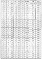
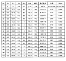
- (W-type refractive index distribution design parameters) 3 to 6 are diagrams showing design parameters and optical characteristics of the W-type refractive index distribution set so that the cutoff wavelength is 1500 nm.
- FIG. 7 is a diagram showing design parameters and optical characteristics of a W-type refractive index distribution set so that the cutoff wavelength is 1400 nm.
- FIG. 8 is a diagram showing design parameters and optical characteristics of a W-type refractive index distribution set so that the cutoff wavelength is 1300 nm. In each figure, the optical characteristics are values at a wavelength of 1550 nm.
- Ra2 means b / a, which is the ratio of the outer diameter 2b of the outer peripheral core portion to the diameter 2a of the central core portion
- Aeff means the effective core sectional area
- MFD means the mode field diameter.
- dispersion means chromatic dispersion
- Slope means dispersion slope.
- E is a symbol representing a power of 10, for example, “6.21E-3” means “6.21 ⁇ 10 ⁇ 3 ”.
- the central core diameter 2a is 11.2 ⁇ m to 23.9 ⁇ m
- the relative refractive index difference ⁇ 1 is 0.1% to 0.3%
- the relative refractive index difference ⁇ 2 is set.
- the optical characteristics are such that the cutoff wavelength is 1300 nm to 1500 nm, and the light is single mode at a wavelength of 1550 nm.
- W-type refractive index having an effective core area of 100 ⁇ m 2 or more, preferably 300 ⁇ m 2 or more, and a bending loss of 30 dB / m or less, preferably 10 dB / m or less, more preferably 1 dB / m or less. Distribution can be realized.
- the holes do not substantially contribute to light confinement and wave guide in the core portion, and do not substantially affect the effective core cross-sectional area or wavelength dispersion characteristics. That is, the confinement loss in the fundamental mode of the waveguide mode of light generated by the presence of the holes is sufficiently increased.
- FIGS. 9A to 9C are schematic cross-sectional views of a clad portion in which 12, 18, or 24 holes are arranged.
- the hole diameter is d
- the distance of the center of the hole from the center of the cladding is L.
- FIG. 10 is a diagram showing design parameters and optical characteristics of a clad portion having only a hole without having a core portion.
- the optical characteristics are 3 dB / m or more,
- a sufficiently large fundamental mode confinement loss of 20 dB / m or more can be realized.
- a very large fundamental mode confinement loss of 100 dB / m or more is realized.
- the effective core area (Aeff) is as large as 1000 ⁇ m 2 or more. From this point, it is considered that the waveguide mode of light is an extremely leaky mode.
- the separation distance L is up to 50 ⁇ m, but the separation distance L is not limited to this. That is, as shown in FIG. 10, the greater the separation distance L, the greater the confinement loss. Therefore, when the clad diameter is larger than 125 ⁇ m, the separation distance L may be set larger.
- the separation distance L and the number of holes are the same, the smaller the hole diameter d, the greater the confinement loss, which is preferable.
- the pore diameter is at least a size that can exert the effect of reducing the microbend loss, for example, 2 ⁇ m or more.
- the distance L and the hole diameter d are the same, the smaller the number of holes, the greater the confinement loss, which is preferable.
- the number of holes is at least an effect of reducing the microbend loss. For example, 12 or more.
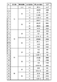
- FIG. 11 is a diagram showing design parameters and optical characteristics of the W-type refractive index distribution selected from FIGS.
- FIG. 12 is a diagram showing design parameters and optical characteristics of the hole structure selected from FIG.
- optical characteristics of an optical fiber configured by combining the W-type refractive index distribution and the hole structure shown in FIGS. 11 and 12 will be described.
- FIG. 13 is a diagram showing design parameters of an optical fiber configured by combining the W-type refractive index distribution and the hole structure shown in FIGS.
- “No. 43-5” means that the design parameter “No. 43” in FIG. 11 is combined with the design parameter “No. 5” in FIG. To do.
- FIG. 14 is a diagram showing optical characteristics of the optical fiber having the design parameters shown in FIG.
- the optical fibers shown in FIG. 14 each have “Aeff change rate”, “dispersion change rate”, and “Slope change rate” of ⁇ 1% or less. Therefore, in the optical fiber shown in FIG. 14, the holes do not substantially affect the effective core area or the wavelength dispersion characteristics of the core portion.
- the optical fiber shown in FIG. 14 has “Aeff change rate”, “dispersion change rate”, and “Slope change rate” of ⁇ 1% or less, but these are ⁇ 10% or less, preferably ⁇ 5% or less.
- the holes do not substantially affect the effective core cross-sectional area or wavelength dispersion characteristics of the core portion.
- the optical fiber according to the first embodiment has a W-type refractive index distribution, but the optical fiber according to the second embodiment has a single-peak type refractive index distribution. It is.
- FIG. 15 is a schematic cross-sectional view of an optical fiber according to the second embodiment.
- the optical fiber 20 includes a core portion 21 located at the center and a clad portion 22 located on the outer periphery of the core portion 21.
- the clad portion 22 is formed at a position separated from the core portion 21 by a predetermined distance, and has twelve holes 22a arranged in a circle at an equal angle with the core portion 21 as the center.
- the number of holes is an example, and is not limited to twelve.
- the core portion 21 is made of quartz glass containing a dopant that increases the refractive index.
- the clad portion 22 is made of pure quartz glass.
- FIG. 16 is a diagram showing a refractive index distribution in the vicinity of the core portion 21 of the optical fiber shown in FIG.
- the distribution profile P ⁇ b> 4 indicates the refractive index distribution of the core portion 21.
- the distribution profile P5 indicates the refractive index distribution of the cladding part 22.
- the relative refractive index difference of the core portion 21 with respect to the cladding portion 22 is assumed to be ⁇ .
- the optical fiber 20 has a so-called unimodal refractive index distribution in which the refractive index distribution has a single peak.
- the diameter of the core portion 21 is 2a.
- the core part diameter 2a is a diameter at a position where the relative refractive index difference is 0% at the boundary between the core part 21 and the clad part 22.
- the optical fiber 20 confines light in the core portion 21 so that most of the light field is distributed in the core portion 21 by a single-peak refractive index distribution formed by the core portion 21 and the cladding portion 22. To guide.
- the hole 22a of the cladding part 22 has a hole diameter of d, and is spaced from the core part 21 by a distance that does not substantially affect the effective core cross-sectional area or wavelength dispersion characteristics in the core part 21. Is formed. Let L be the distance from the center of the core portion 21 at the center of the hole 22a.
- the air holes 22 a do not substantially affect the effective core cross-sectional area or the wavelength dispersion characteristic in the core portion 21, and the core portion 21 has the effect of reducing the microbend loss at 21.
- the optical fiber 20 has high design freedom and high manufacturability.
- the optical fiber according to the second embodiment will be described more specifically with reference to a calculation result using a simulation by a finite element method.
- the optical characteristics of an optical fiber having a single-peaked refractive index profile but no holes will be compared with the optical characteristics of an optical fiber configured by combining this with a hole structure.
- FIG. 17 is a diagram showing design parameters, a cross-sectional structure, and optical characteristics of an optical fiber having a single-peak type refractive index distribution but having no holes, and an optical fiber configured by combining this with a hole structure. It is.
- “No. 1” is an optical fiber having a single-peak type refractive index distribution but no voids
- the core portion diameter 2a is 12.2 ⁇ m
- the relative refractive index difference ⁇ is 0. .22%.
- “No. 2” is a combination of “No. 1” optical fiber with a hole structure having a hole diameter d of 2.5 ⁇ m, a separation distance L of 50 ⁇ m, and 12 holes.
- “No. 3” is a combination of “No.
- optical fiber with a hole structure having a hole diameter d of 2.5 ⁇ m, a separation distance L of 50 ⁇ m, and a number of holes of 24. Further, the optical characteristics are values at a wavelength of 1550 nm unless otherwise specified.
- FIG. 17 shows the confinement loss of the first higher-order mode at wavelengths of 1550 nm and 1530 nm.
- the confinement loss of the first higher-order mode is high in order to prevent the double clad structure from being formed by the holes and the multimode operation.
- the confinement loss cannot be defined when the optical fiber is in a straight state, so that the diameter of the optical fiber is very high, ie, 60 m. The bending loss when bending with a large diameter is calculated, and this is taken as the confinement loss.
- the combination of the hole structures is effective.
- the core cross-sectional area, chromatic dispersion, and dispersion slope are almost unchanged. That is, when calculating the Aeff change rate, the dispersion change rate, and the slope change rate in the same manner as in FIG. 14, all are ⁇ 5% or less, and the void structure substantially affects the effective core cross-sectional area or wavelength dispersion characteristics. Not given.
- the microbend loss is reduced by the action effect of the holes, as in the optical fiber according to the first embodiment.
- the confinement loss of the first higher-order mode is 1 dB / m.
- the rule that the wavelength is the cutoff wavelength is adopted.
- the optical fiber of “No. 2” shown in FIG. 17 has a confinement loss of 2.51 dB / m in the first higher-order mode at a wavelength of 1530 nm.
- the optical fiber of “No. 3” has a confinement loss of the first higher-order mode at a wavelength of 1530 nm of 1.67 dB / m. Accordingly, since the optical fibers of “No. 2” and “No. 3” both have a cutoff wavelength shorter than 1530 nm, it is sufficient in the most frequently used C band and L band (1530 to 1630 nm). It operates in single mode.
- a relative refractive index difference ⁇ is 0.16% ⁇ 0.33%, if the core section diameter of 10 [mu] m-14 [mu] m, satisfies the property that the effective core area at the wavelength of 1550nm is 100 [mu] m 2 - 185 .mu.m 2
- the number of holes is 12 or more, the hole diameter is 2.5 ⁇ 0.5 ⁇ m, and the separation distance is 40 ⁇ m or more, the single mode operation is performed in the C band and the L band, and the micro wave at the wavelength of 1550 nm is obtained. It satisfies the characteristic that the bend loss is reduced to 80% or less of the microbend loss when there is no void.
- the center of the hole is separated from the outer edge of the cladding part by 2.5 ⁇ m or more in order to ensure the mechanical strength of the optical fiber.
- FIG. 18 is a diagram showing optical characteristics of optical fibers of Examples and Comparative Examples.
- FIG. 19 is a diagram showing the wavelength dependence of the microbend loss of the optical fibers of the example and the comparative example.
- the optical characteristics shown in FIG. 18 are values at a wavelength of 1550 nm excluding the cutoff wavelength.
- the microbend loss is the transmission loss when each optical fiber is wound around a bobbin wound with # 1000 sandpaper on the surface, and when each optical fiber is unwound from the bobbin to form a bundle. The difference between these transmission losses was adopted as the microbend loss.
- the ratio of the difference in effective core cross-sectional area of the example with respect to the comparative example was extremely small, about -1.4%.
- the cut-off wavelength was the same.
- the optical fibers according to the first and second embodiments are made of pure silica glass containing a dopant that increases the refractive index such as germanium (Ge) in the W-shaped central core portion or the single-peak core portion, and the cladding portion is
- pure silica glass does not contain a dopant for adjusting the refractive index, it is not particularly limited as long as a desired refractive index distribution shape can be realized.
- FIG. 20 is a schematic cross-sectional view of an optical fiber according to a modification of the second embodiment of the present invention.
- the optical fiber 30 includes a core portion 31 located at the center and a clad portion 32 located on the outer periphery of the core portion 31.
- the clad part 32 is formed at a position separated from the core part 31 by a predetermined distance, and has twelve holes 32a arranged in a circle at an equal angle around the core part 31.
- the clad portion 32 includes an inner circumference clad portion 321 located on the outer circumference of the core portion 31 and an outer circumference clad portion 322 located on the outer circumference of the inner circumference clad portion 321.
- the air holes 32 a are formed in the outer peripheral cladding portion 322, but may be formed in the inner peripheral cladding portion 321.
- the core portion 31 has a step index type single-peaked refractive index profile and is made of pure silica glass.
- the inner peripheral cladding part 321 is made of quartz glass containing fluorine
- the outer peripheral cladding part 322 is made of pure silica glass.
- the core part diameter 2a and the relative refractive index difference ⁇ are defined similarly to the optical fiber 20 according to the second embodiment, and can be set to desired values.
- the optical fiber 30 has a lower transmission loss because the core portion 31 is made of pure silica glass that does not contain a dopant for adjusting the refractive index. .
- the outer peripheral cladding part 322 is made of pure silica glass like the core part 31. For this reason, when the optical fiber 30 is manufactured by drawing, the outer clad portion 322 having higher viscosity than the inner clad portion 321 containing fluorine is present, so that stress applied to the base material during drawing is caused by the core portion 31. Concentrating on is prevented. As a result, since the distortion remaining in the core portion 31 is reduced, the transmission loss is further reduced.
- FIG. 21 is a diagram for explaining an example of the optical fiber manufacturing method according to the present invention.
- the glass base material 41 is formed using a known VAD method or the like.
- the glass base material 41 includes a core forming portion 411 for forming the core portion 21 and a clad forming portion 412 located on the outer periphery of the core forming portion 411 and forming a part of the cladding portion 32. Is done.
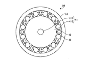
- a hollow glass capillary 42 for forming the holes 32a and a solid glass rod 43 for arranging the glass capillaries 42 at a desired interval are arranged.
- the optical fiber 20 shown in FIG. 15 can be manufactured.
- optical fiber manufacturing method is not limited to the above-described method.
- a hole may be drilled in the glass base material 41 with a drill or the like, and the optical fiber may be manufactured by drawing the hole. .
- FIG. 22 is a diagram illustrating a refractive index profile that can be used in the present invention.
- 22A to 22E show refractive index distributions called a staircase profile, a segment core profile, a trench profile, a W + side core profile, and a ring profile, respectively.
- These refractive index distributions can be designed so as to realize desired optical characteristics using ⁇ 1, ⁇ 2, ⁇ 3, 2a, 2b, and 2c shown in the figure as design parameters.
- a refractive index distribution obtained by appropriately combining the refractive index distributions shown in FIG. 22 may be used.
- the optical fiber according to the present invention is formed at a position separated by a distance that does not substantially affect the effective core cross-sectional area or chromatic dispersion characteristics in the core portion, and reduces the microbend loss in the core portion.
- a hole having a function it has a hole (a hole for light confinement assist) provided in the vicinity of the core part in order to assist light confinement in the core part like a known hole assist optical fiber. It can also be configured. That is, as described above, since the optical fiber according to the present invention can use any refractive index distribution as a refractive index distribution that realizes light confinement, the refraction formed by the contribution of light confinement assist holes. Of course, rate distribution is also available.
- the optical fiber is made of a silica-based glass material.
- the constituent material of the optical fiber according to the present invention is not limited to this, and an optical fiber such as another glass material or a plastic material is used.
- the optical material which can be used can be utilized suitably.
- the optical fiber according to the present invention is suitable mainly for use in optical communication.
Landscapes
- Physics & Mathematics (AREA)
- General Physics & Mathematics (AREA)
- Optics & Photonics (AREA)
- Optical Fibers, Optical Fiber Cores, And Optical Fiber Bundles (AREA)
Abstract
光を閉じ込めて導波するコア部と、前記コア部の外周に形成されたクラッド部と、を備え、前記クラッド部は、前記コア部から、前記コア部における有効コア断面積または波長分散特性に実質的に影響を与えない距離だけ離間した位置に形成され、前記コア部におけるマイクロベンド損失を低減する空孔を有する。好ましくは、当該光ファイバの有効コア断面積または波長分散特性の値と当該光ファイバにおいて前記空孔が無いとした場合の有効コア断面積または波長分散特性の値との差分と、前記空孔が無いとした場合の有効コア断面積または波長分散特性の値との比がそれぞれ±10%以内である。これによって、製造性と光学設計の自由度とが高い光ファイバが提供される。
Description
本発明は、光ファイバに関するものである。
近年のインターネットトラヒックの劇的な増大に伴い、一本の光ファイバを伝搬する光のパワーも増大していることから、光ファイバ内の非線形光学現象やファイバヒューズが大きな問題となってきている。これらを解決する方法としては、光ファイバの有効コア断面積(Aeff)を拡大することが有効である。しかしながら、従来のソリッド型光ファイバにおいては、有効コア断面積を拡大しつつ、通信波長帯において単一モード伝送を実現しようとした場合、マクロの曲げ損失や、マイクロベンド損失が大きくなってしまうという問題がある。なお、マイクロベンド損失は、光ファイバに側圧が加えられたときに、光ファイバに微小な曲げが加えられることによる伝送損失の増加量として定義される。
有効コア断面積を拡大しながら単一モード伝送を実現したときの、マクロの曲げ損失を低減する手法としては、屈折率分布の最適化が提案されている。例えば、非特許文献1では、トレンチ型の屈折率分布を最適化することで有効コア断面積を120μm2まで拡大した光ファイバが提案されている。また、非特許文献2では、W型の屈折率分布を最適化することで有効コア断面積を134μm2まで拡大した結果が報告されている。
Marianne Bigot-Astruc, Frans Gooijer, Nelly Montaigne, Pierre Sillard, "Trench-Assisted Profiles for Large-Effective-Area Single-Mode Fibers," ECOC2008、Mo.4.B.1
Yoshinori Yamamoto, Masaaki Hirano, Kazuya Kuwahara, Takashi Sasaki "OSNR-Enhancing Pure-Silica-Core Fiber with Large Effective Area and Low Attenuation," OFC/NFOEC2010、OTuI2
Yukihiro Tsuchida, Kazunori Mukasa, Takeshi Yagi, "Comparison of microbending loss characteristics between LMA holey fibers and conventional LMA fibers," OFC/NFOEC2010、OTuI7
Takashi Matsui, Taiji Sakamoto, Kyozo Tsujikawa, and Shigeru Tomita, "Single-mode photonic crystal fiber with low bending loss and Aeff of > 200 μm2 for ultra high-speed WDM transmission," PDPA2 OFC/NFOEC 2010
しかしながら、非特許文献2中にも記載されているように、更なる有効コア断面積の拡大のためには、マイクロベンド損失の増大が最大の障壁となっている。また、マイクロベンド損失の増大は、有効コア断面積の拡大に限らず、光ファイバの光学特性の設計の自由度を制限する要因となっている。一方で、非特許文献3では、ファイバ断面中に空孔構造を設けることで、マイクロベンド損失の抑制が可能である事が示されている。しかしながら、現状の技術では、ガラス中に配置された多数の空孔からなる空孔構造によって光の導波を実現する光ファイバ(例えばホーリーファイバ:HF)は、多数の空孔を高精度に形成する際の製造上の困難性のため、安定した量産が難しいと言う課題がある。
本発明は、上記に鑑みてなされたものであって、製造性と光学設計の自由度とが高い光ファイバを提供することを目的とする。
上述した課題を解決し、目的を達成するために、本発明に係る光ファイバは、光を閉じ込めて導波するコア部と、前記コア部の外周に形成されたクラッド部と、を備え、前記クラッド部は、前記コア部から、前記コア部における有効コア断面積または波長分散特性に実質的に影響を与えない距離だけ離間した位置に形成され、前記コア部におけるマイクロベンド損失を低減する空孔を有することを特徴とする。
また、本発明に係る光ファイバは、上記の発明において、当該光ファイバの有効コア断面積または波長分散特性の値と当該光ファイバにおいて前記空孔が無いとした場合の有効コア断面積または波長分散特性の値との差分と、前記空孔が無いとした場合の有効コア断面積または波長分散特性の値との比がそれぞれ±10%以内であることを特徴とする。
また、本発明に係る光ファイバは、上記の発明において、前記空孔の中心が、前記コア部の中心から25μm以上離間していることを特徴とする。
また、本発明に係る光ファイバは、上記の発明において、前記クラッド部は、36個以下の前記空孔を有し、前記空孔の空孔直径が10μm以下であることを特徴とする。
また、本発明に係る光ファイバは、上記の発明において、波長1550nmにおける前記有効コア断面積が100μm2以上であることを特徴とする。
また、本発明に係る光ファイバは、上記の発明において、前記コア部は、前記クラッド部よりも屈折率が高い中心コア部と、前記中心コア部の外周に位置し、前記クラッド部よりも屈折率が低い外周コア部とからなり、前記クラッド部に対する前記中心コア部の比屈折率差が0.1%~0.3%であり、前記クラッド部に対する前記外周コア部の比屈折率差が-0.2%~-0.05%であり、前記中心コア部の直径が11.2μm~23.9μmであり、前記中心コア部の直径に対する前記外周コア部の外径の比が2.0~4.0であることを特徴とする。
また、本発明に係る光ファイバは、上記の発明において、前記コア部は、単峰型の屈折率分布を有し、波長1550nmにおける前記有効コア断面積が100μm2~185μm2であることを特徴とする。
また、本発明に係る光ファイバは、上記の発明において、前記クラッド部は、前記コア部を中心として円形に配列した前記空孔を12個以上有し、前記空孔の空孔直径が2.5±0.5μmであり、前記空孔の中心が、前記コア部の中心から40μm以上離間しているとともに当該クラッド部の外縁から2.5μm以上離間していることを特徴とする。
また、本発明に係る光ファイバは、上記の発明において、前記クラッド部に対する前記コア部の比屈折率差が0.16%~0.33%であり、前記コア部の直径が10μm~14μmであることを特徴とする。
また、本発明に係る光ファイバは、上記の発明において、波長1550nmにおける当該光ファイバのマイクロベンド損失は、当該光ファイバにおいて前記空孔が無いとした場合のマイクロベンド損失の80%以下であることを特徴とする。
本発明によれば、製造性と光学設計の自由度とが高い光ファイバを実現できるという効果を奏する。
以下に、図面を参照して本発明に係るホーリーファイバの実施の形態を詳細に説明する。なお、この実施の形態によりこの発明が限定されるものではない。また、本明細書においては、カットオフ波長とは、特に言及しない限り、ITU-T(国際電気通信連合)G.650.1で定義するファイバカットオフ波長を意味する。また、曲げ損失とは、直径20mmにおけるマクロの曲げ損失を意味する。また、本明細書において特に定義しない用語については、ITU-TG.650.1における定義、測定方法に従うものとする。
(実施の形態1)
図1は、本発明の実施の形態1に係る光ファイバの模式的な断面図である。図1に示すように、この光ファイバ10は、中心に位置するコア部11と、コア部11の外周に位置するクラッド部12とを備える。
図1は、本発明の実施の形態1に係る光ファイバの模式的な断面図である。図1に示すように、この光ファイバ10は、中心に位置するコア部11と、コア部11の外周に位置するクラッド部12とを備える。
コア部11は、中心コア部111と、中心コア部111の外周に位置する外周コア部112とからなる。また、クラッド部12は、コア部11から所定の距離だけ離間した位置に形成され、コア部11を中心として等角度で円形に配置された24個の空孔12aを有する。なお、空孔の数は一例であって、24個に限定はされない。
また、中心コア部111は、ゲルマニウム(Ge)等の屈折率を高めるドーパントを含む石英ガラスからなる。外周コア部112は、フッ素(F)等の屈折率を低めるドーパントを含む石英ガラスからなる。クラッド部12は、屈折率を調整するドーパントを含まない純石英ガラスからなる。その結果、中心コア部111はクラッド部12よりも屈折率が高く、外周コア部112はクラッド部12よりも屈折率が低くなっている。
図2は、図1に示す光ファイバのコア部11近傍の屈折率分布を示す図である。図2において、分布プロファイルP1は中心コア部111の屈折率分布を示している。分布プロファイルP2は外周コア部112の屈折率分布を示している。分布プロファイルP3はクラッド部12の屈折率分布を示している。このように、この光ファイバ10は、外周コア部112の屈折率がクラッド部12の屈折率よりも低い、いわゆるW型の屈折率分布を有している。ここで、図2に示すように、クラッド部12に対する中心コア部111の比屈折率差をΔ1とし、クラッド部12に対する外周コア部112の比屈折率差をΔ2とする。また、中心コア部111の直径を2a、外周コア部112の外径を2bとする。なお、中心コア部直径2aは、中心コア部111と外周コア部112との境界において比屈折率差Δ1が0%となる位置での径とする。また、外周コア部外径2bは、外周コア部112とクラッド部12との境界において、比屈折率差が比屈折率差Δ2の1/2の値となる位置での径とする。
この光ファイバ10は、コア部11とクラッド部12とが形成するW型の屈折率分布によって、光のフィールドの殆どがコア部11内に分布するようにして、コア部11に光を閉じ込めて導波する。
つぎに、クラッド部12の空孔12aについて説明する。空孔12aは、空孔直径がdであり、コア部11から、コア部11における有効コア断面積または波長分散特性に実質的に影響を与えない距離だけ離間した位置に形成されている。なお、空孔12aの中心のコア部11の中心からの離間距離をLとする。
このように、光ファイバ10では、空孔12aが、コア部11における有効コア断面積または波長分散特性に実質的に影響を与えない。それとともに、空孔12aが、光ファイバ10が受ける側圧に対するバッファ層としての役割を果たし、光ファイバのプライマリ被覆と同様に側圧を吸収、分散させる機能を有することとなるため、コア部11におけるマイクロベンド損失を低減する効果を奏する。その結果、この光ファイバ10は、従来光ファイバの光学特性の設計の自由度の制限要因となっていたマイクロベンド損失の増大が抑制されているため、設計の自由度が高いものとなり、たとえば拡大された有効コア断面積を実現できる。これととともに、光ファイバ10では、空孔12aはコア部11における光の導波には実質的に寄与していないため、必要な空孔12aの数や位置、大きさの精度が緩和され、製造性が高いものとなる。
つぎに、有限要素法によるシミュレーションを用いた計算結果を参照して、本実施の形態1に係る光ファイバの好ましい設計についてより具体的に説明する。以下では、はじめに、図2に示したW型屈折率分布の設計パラメータの好ましい値を説明する。つぎに、空孔の好ましい構造と設計パラメータとについて説明する。最後に、これらの好ましいW型屈折率分布と空孔構造とを組み合わせて構成された光ファイバの光学特性について説明する。
(W型屈折率分布の設計パラメータ)
図3~図6は、カットオフ波長が1500nmになるように設定したW型屈折率分布の設計パラメータおよび光学特性を示す図である。図7は、カットオフ波長が1400nmになるように設定したW型屈折率分布の設計パラメータおよび光学特性を示す図である。図8は、カットオフ波長が1300nmになるように設定したW型屈折率分布の設計パラメータおよび光学特性を示す図である。なお、各図において、光学特性は、波長1550nmにおける値である。また、「Ra2」は外周コア部外径2bと中心コア部直径2aとの比であるb/aを意味し、「Aeff」は有効コア断面積を意味し、「MFD」はモードフィールド径を意味し、「分散」は波長分散を意味し、「Slope」は分散スロープを意味する。また、曲げ損失の値において、「E」は10のべき乗を表す記号であり、たとえば「6.21E-3」は「6.21×10-3」を意味する。
図3~図6は、カットオフ波長が1500nmになるように設定したW型屈折率分布の設計パラメータおよび光学特性を示す図である。図7は、カットオフ波長が1400nmになるように設定したW型屈折率分布の設計パラメータおよび光学特性を示す図である。図8は、カットオフ波長が1300nmになるように設定したW型屈折率分布の設計パラメータおよび光学特性を示す図である。なお、各図において、光学特性は、波長1550nmにおける値である。また、「Ra2」は外周コア部外径2bと中心コア部直径2aとの比であるb/aを意味し、「Aeff」は有効コア断面積を意味し、「MFD」はモードフィールド径を意味し、「分散」は波長分散を意味し、「Slope」は分散スロープを意味する。また、曲げ損失の値において、「E」は10のべき乗を表す記号であり、たとえば「6.21E-3」は「6.21×10-3」を意味する。
図3~図8に示すように、設計パラメータとして、中心コア部直径2aを11.2μm~23.9μm、比屈折率差Δ1を0.1%~0.3%、比屈折率差Δ2を-0.2%~-0.05%、比Ra2を2.0~4.0に設定することによって、光学特性として、カットオフ波長が1300nm~1500nmであることによって波長1550nmでシングルモードで光を導波でき、有効コア断面積が100μm2以上、好ましくは300μm2以上であり、曲げ損失が30dB/m以下、好ましくは10dB/m以下、さらに好ましくは1dB/m以下であるW型屈折率分布を実現することができる。
(空孔の構造と設計パラメータ)
つぎに、空孔の好ましい構造と設計パラメータとについて説明する。上述したように、空孔は、コア部における光の閉じ込め、導波には実質的に寄与せず、有効コア断面積または波長分散特性に実質的に影響を与えないようにする。すなわち、空孔の存在により発生する光の導波モードの基底モードの閉じ込め損失を十分に大きくする。
つぎに、空孔の好ましい構造と設計パラメータとについて説明する。上述したように、空孔は、コア部における光の閉じ込め、導波には実質的に寄与せず、有効コア断面積または波長分散特性に実質的に影響を与えないようにする。すなわち、空孔の存在により発生する光の導波モードの基底モードの閉じ込め損失を十分に大きくする。
ここでは、純石英ガラスからなり、コア部を有さないクラッド部だけの構造に、空孔のみをクラッド部の中心に対して等角度で円形に12~36個だけ配置したものについての光学特性の計算結果を説明する。なお、空孔の数が36個以下であれば、空孔の形成が容易であり、製造性が高く好ましい。また、図9(a)~(c)は、空孔を12個、18個、または24個配置したクラッド部の模式的な断面図である。ここで、空孔直径をd、クラッド部の中心からの空孔の中心の離間距離をLとする。
図10は、コア部を有さず空孔のみを有するクラッド部の設計パラメータおよび光学特性を示す図である。図10に示すように、設計パラメータとして、空孔数を12~36、離間距離Lを25μm~50μm、空孔直径dを2μm~10μmに設定することによって、光学特性として、3dB/m以上、好ましくは20dB/m以上の十分に大きい基底モードの閉じ込め損失を実現できる。特に、図中で下線を付した例では、100dB/m以上のきわめて大きい基底モードの閉じ込め損失を実現している。また、その場合の有効コア断面積(Aeff)は1000μm2以上ときわめて大きくなっており、この点からも、光の導波モードが極めてリーキーなモードになっていると考えられる。
なお、図10では、通常の光ファイバのクラッド径が125μmであることを考慮して、離間距離Lの設定を50μmまでとしているが、離間距離Lはこれに限定されない。すなわち、図10に示すように、離間距離Lが大きい程閉じ込め損失は大きくなる。したがって、クラッド径を125μmより大きくする場合には、離間距離Lをさらに大きく設定してもよい。
また、図10に示すように、離間距離Lと空孔数とが同じであれば、空孔直径dが小さいほど閉じ込め損失が大きいので好ましい。ただし、空孔直径は、少なくともマイクロベンド損失を低減する効果が発揮できる程度の大きさ、たとえば2μm以上とすることが好ましい。同様に、離間距離Lと空孔直径dとが同じであれば、空孔数が少ないほど閉じ込め損失が大きいので好ましいが、空孔数については、少なくともマイクロベンド損失を低減する効果が発揮できる程度の数、たとえば12個以上とする。
(光ファイバの光学特性)
つぎに、上述したW型屈折率分布と空孔構造とを組み合わせて構成された光ファイバの光学特性について説明する。図11は、図4、5から選択したW型屈折率分布の設計パラメータおよび光学特性を示す図である。図12は、図10から選択した空孔構造の設計パラメータおよび光学特性を示す図である。以下では、図11、12に示すW型屈折率分布と空孔構造とを組み合わせて構成された光ファイバの光学特性について説明する。
つぎに、上述したW型屈折率分布と空孔構造とを組み合わせて構成された光ファイバの光学特性について説明する。図11は、図4、5から選択したW型屈折率分布の設計パラメータおよび光学特性を示す図である。図12は、図10から選択した空孔構造の設計パラメータおよび光学特性を示す図である。以下では、図11、12に示すW型屈折率分布と空孔構造とを組み合わせて構成された光ファイバの光学特性について説明する。
図13は、図11、12に示すW型屈折率分布と空孔構造とを組み合わせて構成された光ファイバの設計パラメータを示す図である。なお、図13において、たとえば「No.43-5」とは、図11の「No.43」の設計パラメータと図12の「No.5」の設計パラメータとを組み合わせて構成されることを意味する。
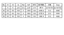
図14は、図13に示した設計パラメータの光ファイバの光学特性を示す図である。図14において、「Aeff変化率」とは、図14に示す「Aeff」の値と図11に示す空孔構造が無い場合の「Aeff」の値との差分と、空孔構造が無い場合の「Aeff」の値との比を示す値である。すなわち、たとえば、「No.43-5」の「Aeff変化率」は、図14の「No.43-5」の「Aeff」の値である154.5と、図11の「No.43」の「Aeff」の値である154.4との差分と、154.4との比、すなわち(154.5-154.4)/154.4=0.065%である。
また、「分散変化率」、「Slope変化率」についても、図14に示す値と図11に示す空孔構造が無い場合の値との差分と、空孔構造が無い場合の値の比を示す値である。
図14に示す光ファイバは、いずれも「Aeff変化率」、「分散変化率」、「Slope変化率」が±1%以下である。したがって、図14に示す光ファイバは、空孔がコア部の有効コア断面積または波長分散特性に実質的に影響を与えていないものとなっている。
なお、図14に示す光ファイバは、「Aeff変化率」、「分散変化率」、「Slope変化率」が±1%以下であるが、これらが±10%以下、好ましくは±5%以下の光ファイバであれば、空孔がコア部の有効コア断面積または波長分散特性に実質的に影響を与えていないと考えることができる。
(実施の形態2)
つぎに、本発明の実施の形態2について説明する。実施の形態1に係る光ファイバは、W型の屈折率分布を有しているものであるが、本実施の形態2に係る光ファイバは、単峰型の屈折率分布を有しているものである。
つぎに、本発明の実施の形態2について説明する。実施の形態1に係る光ファイバは、W型の屈折率分布を有しているものであるが、本実施の形態2に係る光ファイバは、単峰型の屈折率分布を有しているものである。
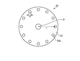
図15は、本実施の形態2に係る光ファイバの模式的な断面図である。図15に示すように、この光ファイバ20は、中心に位置するコア部21と、コア部21の外周に位置するクラッド部22とを備える。クラッド部22は、コア部21から所定の距離だけ離間した位置に形成され、コア部21を中心として等角度で円形に配置された12個の空孔22aを有する。なお、空孔の数は一例であって、12個に限定はされない。
また、コア部21は、屈折率を高めるドーパントを含む石英ガラスからなる。クラッド部22は、純石英ガラスからなる。
図16は、図15に示す光ファイバのコア部21近傍の屈折率分布を示す図である。図16において、分布プロファイルP4はコア部21の屈折率分布を示している。分布プロファイルP5はクラッド部22の屈折率分布を示している。ここで、クラッド部22に対するコア部21の比屈折率差をΔとする。このように、この光ファイバ20は、屈折率分布が単一のピークを有するいわゆる単峰型の屈折率分布を有している。また、コア部21の直径を2aとする。コア部直径2aは、コア部21とクラッド部22との境界において、比屈折率差が0%の値となる位置での径とする。
この光ファイバ20は、コア部21とクラッド部22とが形成する単峰型の屈折率分布によって、光のフィールドの殆どがコア部21内に分布するようにして、コア部21に光を閉じ込めて導波する。
また、クラッド部22の空孔22aについては、空孔直径がdであり、コア部21から、コア部21における有効コア断面積または波長分散特性に実質的に影響を与えない距離だけ離間した位置に形成されている。空孔22aの中心のコア部21の中心からの離間距離をLとする。
このように、光ファイバ20は、実施の形態1に係る光ファイバと同様に、空孔22aが、コア部21における有効コア断面積または波長分散特性に実質的に影響を与えないとともに、コア部21におけるマイクロベンド損失を低減する効果を奏する。その結果、この光ファイバ20は、設計の自由度が高いととともに、製造性が高いものとなる。
つぎに、有限要素法によるシミュレーションを用いた計算結果を参照して、本実施の形態2に係る光ファイバについてより具体的に説明する。以下では、単峰型屈折率分布を有するが空孔の無い構造の光ファイバの光学特性と、これに空孔構造を組み合わせて構成された光ファイバの光学特性とを比較して説明する。
図17は、単峰型屈折率分布を有するが空孔の無い構造の光ファイバとこれに空孔構造を組み合わせて構成された光ファイバとの設計パラメータおよび断面構造と、光学特性とを示す図である。図17に示すように、「No.1」は単峰型屈折率分布を有するが空孔の無い構造の光ファイバであり、そのコア部直径2aは12.2μm、比屈折率差Δは0.22%である。また、「No.2」は、「No.1」の光ファイバに空孔直径dが2.5μm、離間距離Lが50μm、空孔数が12個の空孔構造を組み合わせたものである。また、「No.3」は、「No.1」の光ファイバに空孔直径dが2.5μm、離間距離Lが50μm、空孔数が24個の空孔構造を組み合わせたものである。また、光学特性は、特に言及しない限り波長1550nmにおける値である。
なお、図17には、波長1550nmおよび1530nmにおける第一高次モードの閉じ込め損失を示している。本発明に係る光ファイバでは、空孔によってダブルクラッド構造が形成されて多モード動作することを防止するために、第一高次モードの閉じ込め損失が高いほうが好ましい。なお、「No.1」のように単峰型屈折率分布を有するが空孔の無い構造の光ファイバにおいては、光ファイバが直線状態の場合は閉じ込め損失が定義できないので、直径60mという非常に大きい径で曲げた場合の曲げ損失を計算し、これを閉じ込め損失としている。
図17に示すように、「No.2」、「No.3」の空孔構造を組み合わせた光ファイバと、「No.1」の光ファイバとを比較すると、空孔構造の組み合わせによって、有効コア断面積、波長分散、分散スロープは殆ど変化していない。すなわち、図14と同様にAeff変化率、分散変化率、およびSlope変化率を計算すると、いずれも±5%以下であり、空孔構造が有効コア断面積または波長分散特性に実質的に影響を与えていない。一方、マイクロベンド損失については、実施の形態1に係る光ファイバと同様に、空孔の作用効果によって低減されていると考えられる。
また、空孔構造を有する光ファイバは、厳密なカットオフ波長の定義が難しいが、ここでは、非特許文献4に開示されるように、第一高次モードの閉じ込め損失が1dB/mとなる波長をカットオフ波長であるという規定を採用する。すると、図17に示す「No.2」の光ファイバは、波長1530nmにおける第一高次モードの閉じ込め損失が2.51dB/mである。また、「No.3」の光ファイバは、波長1530nmにおける第一高次モードの閉じ込め損失が1.67dB/mである。したがって、「No.2」、「No.3」の光ファイバは、いずれもカットオフ波長が1530nmより短いことになるので、最も多く使用されているCバンドおよびLバンド(1530~1630nm)において十分にシングルモードで動作するものである。
なお、本実施の形態2に係る光ファイバの設計パラメータは、上記のものに限られない。たとえば、比屈折率差Δが0.16%~0.33%であり、コア部直径が10μm~14μmであれば、波長1550nmにおける有効コア断面積が100μm2~185μm2であるという特性を満たし、空孔数が12個以上であり、空孔直径が2.5±0.5μmであり、離間距離が40μm以上であれば、CバンドおよびLバンドにおいてシングルモード動作し、かつ波長1550nmにおけるマイクロベンド損失が、空孔が無いとした場合のマイクロベンド損失の80%以下に低減されるという特性を満たす。
また、空孔の中心がクラッド部の外縁から2.5μm以上離間していることが、光ファイバの機械的強度を確保するために好ましい。
(実施例、比較例)
つぎに、本発明の実施例、比較例により、本発明をより具体的に説明する。本発明の実施例、比較例として、図17に示した空孔構造を有する「No.2」、空孔構造の無い「No.1」の光ファイバを後述する方法にて製造した。
つぎに、本発明の実施例、比較例により、本発明をより具体的に説明する。本発明の実施例、比較例として、図17に示した空孔構造を有する「No.2」、空孔構造の無い「No.1」の光ファイバを後述する方法にて製造した。
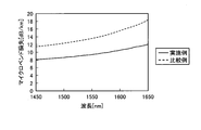
図18は、実施例および比較例の光ファイバの光学特性を示す図である。また、図19は、実施例および比較例の光ファイバのマイクロベンド損失の波長依存性を示す図である。なお、図18に示す光学特性は、カットオフ波長を除き波長1550nmにおける値である。また、マイクロベンド損失については、番手が♯1000のサンドペーパが表面に巻かれたボビンに各光ファイバを巻きつけたときの伝送損失と、各光ファイバをボビンから解いて巻き束の状態としたときの伝送損失とを測定し、これらの伝送損失の差をマイクロベンド損失として採用した。
図18に示すように、比較例に対する実施例の有効コア断面積の差分の比は-1.4%程度ときわめて小さかった。また、カットオフ波長については同一であった。これに対して、図19に示すように、実施例のマイクロベンド損失は、比較例に対して広い波長帯域にわたって大きく低減されており、たとえば波長1550nmでは13.6dB/kmから9.4dB/kmへと低減された。すなわち、差分としては13.6-9.4=4.2dB/kmだけ低減され、割合としては9.4/13.6=約69%に低減された。また、曲げ損失についても大きく低減された。
なお、上記実施の形態1、2に係る光ファイバは、W型の中心コア部または単峰型のコア部にゲルマニウム(Ge)等の屈折率を高めるドーパントを含む純石英ガラスとし、クラッド部は屈折率を調整するドーパントを含まない純石英ガラスとしているが、所望の屈折率分布の形状を実現できるものであれば特に限定されない。
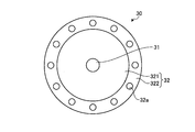
図20は、本発明の実施の形態2の変形例に係る光ファイバの模式的な断面図である。図20に示すように、この光ファイバ30は、中心に位置するコア部31と、コア部31の外周に位置するクラッド部32とを備える。クラッド部32は、コア部31から所定の距離だけ離間した位置に形成され、コア部31を中心として等角度で円形に配置された12個の空孔32aを有する。また、クラッド部32は、コア部31の外周に位置する内周クラッド部321と、内周クラッド部321の外周に位置する外周クラッド部322とからなる。なお、図20では空孔32aは外周クラッド部322に形成されているが、内周クラッド部321に形成されていてもよい。
ここで、この光ファイバ30では、コア部31は、ステップインデックス型の単峰型屈折率分布を有し、純石英ガラスからなる。一方、クラッド部32については、内周クラッド部321がフッ素を含む石英ガラスからなり、外周クラッド部322が純石英ガラスからなる。なお、コア部直径2aや比屈折率差Δについては、実施の形態2に係る光ファイバ20と同様に規定され、所望の値に設定することができる。
この光ファイバ30は、実施の形態2に係る光ファイバ20において得られる効果に加え、コア部31が屈折率調整用のドーパントを含まない純石英ガラスからなるため、伝送損失がより低いものとなる。さらに、この光ファイバ30は、外周クラッド部322がコア部31と同じく純石英ガラスからなる。そのため、この光ファイバ30を線引きして製造する場合には、フッ素を含む内周クラッド部321よりも粘性が高い外周クラッド部322が存在するために、線引き時に母材に掛かる応力がコア部31に集中することが防止される。その結果、コア部31に残留する歪みがより少なくなるので、伝送損失がより一層低いものとなる。
(製造方法)
つぎに、本発明に係る光ファイバの製造方法の一例を、実施の形態2に係る光ファイバ20を製造する場合について説明する。
つぎに、本発明に係る光ファイバの製造方法の一例を、実施の形態2に係る光ファイバ20を製造する場合について説明する。
図21は、本発明に係る光ファイバの製造方法の一例を説明する図である。本製造方法では、はじめにガラス母材41を公知のVAD法等を用いて形成する。このガラス母材41は、コア部21を形成するためのコア形成部411と、コア形成部411の外周に位置し、クラッド部32の一部を形成するためのクラッド形成部412と、から構成される。つぎに、このガラス母材41の外周に、空孔32aを形成するための中空のガラスキャピラリ42と、ガラスキャピラリ42を所望の間隔で配置するための中実のガラスロッド43とを配置する。つぎに、これらのガラス母材41、ガラスキャピラリ42、ガラスロッド43の束をガラス管44に挿入してガラス母材50を形成する。その後、ガラス母材50を公知の線引き装置にて線引きすれば、図15に示す光ファイバ20を製造することができる。
なお、本発明に係る光ファイバの製造方法は、上記のものに限定されず、たとえばガラス母材41にドリル等で空孔を穿設し、これを線引きして光ファイバを製造してもよい。
また、上記実施の形態では、光の閉じ込めを実現する屈折率分布はW型または単峰型であるが、本発明に係る光ファイバの屈折率分布はこれに限定されず、あらゆる屈折率分布を利用できる。図22は、本発明において利用できる屈折率分布を例示する図である。図22(a)~(e)は、それぞれ階段型プロファイル、セグメントコアプロファイル、トレンチ型プロフィル、W+サイドコア型プロフィル、リング型プロファイルと呼ばれる屈折率分布である。これらの屈折率分布は、図示するΔ1、Δ2、Δ3、2a、2b、2cを設計パラメータとして、所望の光学特性を実現するように設計することができる。さらに、図22に示す屈折率分布を適宜組み合わせた屈折率分布を利用してもよい。
また、さらには、本発明に係る光ファイバは、コア部における有効コア断面積または波長分散特性に実質的に影響を与えない距離だけ離間した位置に形成され、コア部におけるマイクロベンド損失を低減する機能を有する空孔の他に、公知の空孔アシスト光ファイバのように、コア部における光の閉じ込めをアシストするためにコア部の近傍に設けた空孔(光閉じ込めアシスト用空孔)を有する構成とすることもできる。すなわち、上述したように、本発明に係る光ファイバは、光の閉じ込めを実現する屈折率分布としてあらゆる屈折率分布を利用できるのであるから、光閉じ込めアシスト用空孔が寄与して形成された屈折率分布も当然利用できるものである。
また、上記実施の形態では、光ファイバは石英系ガラス材料からなるが、本発明に係る光ファイバの構成材料はこれに限定されず、他のガラス材料やプラスチック材料等の光ファイバを構成することができる光学材料を適宜利用できる。
以上のように、本発明に係る光ファイバは、主に光通信の用途に利用して好適なものである。
10~30 光ファイバ
11~31 コア部
12~32 クラッド部
12a~32a 空孔
41 ガラス母材
42 ガラスキャピラリ
43 ガラスロッド
44 ガラス管
50 ガラス母材
111 中心コア部
112 外周コア部
321 内周クラッド部
322 外周クラッド部
411 コア形成部
412 クラッド形成部
P1~P5 分布プロファイル
11~31 コア部
12~32 クラッド部
12a~32a 空孔
41 ガラス母材
42 ガラスキャピラリ
43 ガラスロッド
44 ガラス管
50 ガラス母材
111 中心コア部
112 外周コア部
321 内周クラッド部
322 外周クラッド部
411 コア形成部
412 クラッド形成部
P1~P5 分布プロファイル
Claims (10)
- 光を閉じ込めて導波するコア部と、
前記コア部の外周に形成されたクラッド部と、
を備え、前記クラッド部は、前記コア部から、前記コア部における有効コア断面積または波長分散特性に実質的に影響を与えない距離だけ離間した位置に形成され、前記コア部におけるマイクロベンド損失を低減する空孔を有することを特徴とする光ファイバ。 - 当該光ファイバの有効コア断面積または波長分散特性の値と当該光ファイバにおいて前記空孔が無いとした場合の有効コア断面積または波長分散特性の値との差分と、前記空孔が無いとした場合の有効コア断面積または波長分散特性の値との比がそれぞれ±10%以内であることを特徴とする請求項1に記載の光ファイバ。
- 前記空孔の中心が、前記コア部の中心から25μm以上離間していることを特徴とする請求項1または2に記載の光ファイバ。
- 前記クラッド部は、36個以下の前記空孔を有し、前記空孔の空孔直径が10μm以下であることを特徴とする請求項1~3のいずれか一つに記載の光ファイバ。
- 波長1550nmにおける前記有効コア断面積が100μm2以上であることを特徴とする請求項1~4のいずれか一つに記載の光ファイバ。
- 前記コア部は、前記クラッド部よりも屈折率が高い中心コア部と、前記中心コア部の外周に位置し、前記クラッド部よりも屈折率が低い外周コア部とからなり、前記クラッド部に対する前記中心コア部の比屈折率差が0.1%~0.3%であり、前記クラッド部に対する前記外周コア部の比屈折率差が-0.2%~-0.05%であり、前記中心コア部の直径が11.2μm~23.9μmであり、前記中心コア部の直径に対する前記外周コア部の外径の比が2.0~4.0であることを特徴とする請求項1~5のいずれか一つに記載の光ファイバ。
- 前記コア部は、単峰型の屈折率分布を有し、波長1550nmにおける前記有効コア断面積が100μm2~185μm2であることを特徴とする請求項1または2に記載の光ファイバ。
- 前記クラッド部は、前記コア部を中心として円形に配列した前記空孔を12個以上有し、前記空孔の空孔直径が2.5±0.5μmであり、前記空孔の中心が、前記コア部の中心から40μm以上離間しているとともに当該クラッド部の外縁から2.5μm以上離間していることを特徴とする請求項7に記載の光ファイバ。
- 前記クラッド部に対する前記コア部の比屈折率差が0.16%~0.33%であり、前記コア部の直径が10μm~14μmであることを特徴とする請求項7または8に記載の光ファイバ。
- 波長1550nmにおける当該光ファイバのマイクロベンド損失は、当該光ファイバにおいて前記空孔が無いとした場合のマイクロベンド損失の80%以下であることを特徴とする請求項1~9のいずれか一つに記載の光ファイバ。
Priority Applications (1)
| Application Number | Priority Date | Filing Date | Title |
|---|---|---|---|
| US13/372,044 US8787720B2 (en) | 2010-08-04 | 2012-02-13 | Optical fiber |
Applications Claiming Priority (2)
| Application Number | Priority Date | Filing Date | Title |
|---|---|---|---|
| JP2010-175624 | 2010-08-04 | ||
| JP2010175624A JP5619516B2 (ja) | 2010-08-04 | 2010-08-04 | 光ファイバ |
Related Child Applications (1)
| Application Number | Title | Priority Date | Filing Date |
|---|---|---|---|
| US13/372,044 Continuation US8787720B2 (en) | 2010-08-04 | 2012-02-13 | Optical fiber |
Publications (1)
| Publication Number | Publication Date |
|---|---|
| WO2012017764A1 true WO2012017764A1 (ja) | 2012-02-09 |
Family
ID=45559277
Family Applications (1)
| Application Number | Title | Priority Date | Filing Date |
|---|---|---|---|
| PCT/JP2011/065301 Ceased WO2012017764A1 (ja) | 2010-08-04 | 2011-07-04 | 光ファイバ |
Country Status (3)
| Country | Link |
|---|---|
| US (1) | US8787720B2 (ja) |
| JP (1) | JP5619516B2 (ja) |
| WO (1) | WO2012017764A1 (ja) |
Cited By (2)
| Publication number | Priority date | Publication date | Assignee | Title |
|---|---|---|---|---|
| US11154437B2 (en) | 2013-09-19 | 2021-10-26 | The Procter & Gamble Company | Absorbent cores having material free areas |
| CN115079354A (zh) * | 2022-06-13 | 2022-09-20 | 武汉钧恒科技有限公司 | 一种光模块 |
Families Citing this family (13)
| Publication number | Priority date | Publication date | Assignee | Title |
|---|---|---|---|---|
| JP2011033899A (ja) * | 2009-08-03 | 2011-02-17 | Furukawa Electric Co Ltd:The | ホーリーファイバ |
| US20110091176A1 (en) * | 2009-08-03 | 2011-04-21 | Furukawa Electric Co., Ltd. | Holey fibers |
| JP2011095332A (ja) * | 2009-10-27 | 2011-05-12 | Furukawa Electric Co Ltd:The | 光ファイバの製造方法 |
| JP5520622B2 (ja) * | 2010-01-29 | 2014-06-11 | 古河電気工業株式会社 | フォトニックバンドギャップファイバの製造方法およびフォトニックバンドギャップファイバ |
| JP5416059B2 (ja) | 2010-09-03 | 2014-02-12 | 古河電気工業株式会社 | 光ファイバ |
| JP6035780B2 (ja) * | 2011-08-25 | 2016-11-30 | 住友電気工業株式会社 | 光ファイバ |
| JP6269782B2 (ja) * | 2011-08-25 | 2018-01-31 | 住友電気工業株式会社 | 光ファイバ |
| US10578796B2 (en) | 2016-04-01 | 2020-03-03 | Fujikura Ltd. | Optical fiber and method for manufacturing same |
| JP7228429B2 (ja) * | 2019-03-20 | 2023-02-24 | 三菱電線工業株式会社 | レーザ光伝送用光ファイバ |
| EP3766850B1 (de) * | 2019-07-17 | 2026-02-11 | Heraeus Quarzglas GmbH & Co. KG | Verfahren zur herstellung einer hohlkernfaser und zur herstellung einer vorform für eine hohlkernfaser |
| CN111960660A (zh) * | 2020-08-28 | 2020-11-20 | 烽火通信科技股份有限公司 | 一种抗弯耐辐照单模光纤、光纤预制棒及制备方法 |
| WO2022075118A1 (ja) * | 2020-10-06 | 2022-04-14 | 古河電気工業株式会社 | 光ファイバ |
| EP4266098A4 (en) * | 2020-12-15 | 2024-10-30 | Furukawa Electric Co., Ltd. | OPTICAL FIBER, METHOD FOR DESIGNING AN OPTICAL FIBER AND METHOD FOR MANUFACTURING AN OPTICAL FIBER |
Citations (4)
| Publication number | Priority date | Publication date | Assignee | Title |
|---|---|---|---|---|
| JP2001159721A (ja) * | 1999-12-02 | 2001-06-12 | Fujikura Ltd | 分散補償光ファイバ |
| JP2005208268A (ja) * | 2004-01-22 | 2005-08-04 | Nippon Telegr & Teleph Corp <Ntt> | 光ファイバ |
| JP2009122277A (ja) * | 2007-11-13 | 2009-06-04 | Furukawa Electric Co Ltd:The | 光ファイバおよび光伝送システム |
| JP2009151253A (ja) * | 2007-12-25 | 2009-07-09 | Nippon Telegr & Teleph Corp <Ntt> | 誘導ブリルアン散乱抑圧方法及び光ファイバケーブル |
Family Cites Families (41)
| Publication number | Priority date | Publication date | Assignee | Title |
|---|---|---|---|---|
| JPH10253847A (ja) | 1997-03-11 | 1998-09-25 | Furukawa Electric Co Ltd:The | 分散補償光ファイバ |
| CA2232101A1 (en) | 1997-03-25 | 1998-09-25 | Kazunori Mukasa | Dispersion compensating optical fiber, and wavelength division multiplex light transmission line using the same |
| JPH1184158A (ja) | 1997-09-10 | 1999-03-26 | Furukawa Electric Co Ltd:The | 波長分割多重伝送用の光伝送リンクおよびそのリンクを構成する光ファイバ |
| BR9907052A (pt) | 1998-10-23 | 2000-10-17 | Furukawa Electric Co Ltd | Fibra ótica compensadora de dispersão e linha de transmissão ótica com comprimento de onda multiplexado compreendendo fibra ótica compensadora de dispersão |
| AU2577000A (en) | 1999-02-22 | 2000-09-14 | Furukawa Electric Co. Ltd., The | Optical transmission line, negative dispersion optical fiber used for the optical transmission line, and optical transmission system comprising optical transmission line |
| BR0006845A (pt) | 1999-06-25 | 2001-07-03 | Furukawa Electric Co Ltd | Fibra óptica de compensação de dispersão e linha de transmissão óptica usando a fibra óptica |
| WO2001001179A1 (en) | 1999-06-28 | 2001-01-04 | The Furukawa Electric Co., Ltd. | Optical transmission line |
| EP1124145A1 (en) | 1999-08-20 | 2001-08-16 | The Furukawa Electric Co., Ltd. | Optical fiber and optical transmission line including the same |
| US6766088B2 (en) * | 2000-05-01 | 2004-07-20 | Sumitomo Electric Industries, Ltd. | Optical fiber and method for making the same |
| JP4531954B2 (ja) | 2000-09-01 | 2010-08-25 | 古河電気工業株式会社 | 光ファイバおよびその光ファイバを用いた光伝送路 |
| CA2371285A1 (en) | 2001-03-16 | 2002-09-16 | The Furukawa Electric Co., Ltd | Optical fiber and wavelength division multiplex transmission line |
| CA2380342A1 (en) | 2001-04-13 | 2002-10-13 | The Furukawa Electric Co., Ltd | Dispersion management optical transmission system and optical transmission line |
| JP3869305B2 (ja) | 2001-07-26 | 2007-01-17 | 古河電気工業株式会社 | 光伝送路 |
| JP4413456B2 (ja) | 2001-08-27 | 2010-02-10 | 古河電気工業株式会社 | 負分散光ファイバおよび該負分散光ファイバを用いた光伝送路 |
| JP2003188822A (ja) | 2001-10-10 | 2003-07-04 | Furukawa Electric Co Ltd:The | 光伝送路およびその光伝送路を用いた光伝送システム |
| US7085462B2 (en) | 2001-12-05 | 2006-08-01 | The Furukawa Electric Co., Ltd. | Optical fiber, optical fiber module and optical amplifier |
| AUPR949901A0 (en) * | 2001-12-17 | 2002-01-24 | University Of Sydney, The | Ring structures in optical fibres |
| JP2003241000A (ja) | 2002-02-19 | 2003-08-27 | Furukawa Electric Co Ltd:The | 光ファイバおよびその光ファイバを用いた光増幅器ならびに光伝送システム |
| JP2004012685A (ja) | 2002-06-05 | 2004-01-15 | Furukawa Electric Co Ltd:The | 正分散光ファイバ、それを用いた光伝送路 |
| CN1310047C (zh) | 2002-12-18 | 2007-04-11 | 古河电气工业株式会社 | 光纤和使用它的光传送路 |
| EP2469314B1 (en) * | 2003-04-17 | 2015-07-29 | Nippon Telegraph And Telephone Corporation | Hole-assisted single mode optical fiber |
| US20060133753A1 (en) * | 2004-12-22 | 2006-06-22 | Nelson Brian K | Hole assisted fiber device and fiber preform |
| JP2006317692A (ja) * | 2005-05-12 | 2006-11-24 | Swcc Showa Device Technology Co Ltd | 光ファイバ |
| JP5170852B2 (ja) * | 2005-09-29 | 2013-03-27 | 古河電気工業株式会社 | 光ファイバおよび光伝送媒体 |
| EP2051115A1 (en) | 2007-02-02 | 2009-04-22 | The Furukawa Electric Co., Ltd. | Optical transmission system and dispersion-compensated optical fiber |
| JP2008209654A (ja) | 2007-02-26 | 2008-09-11 | Furukawa Electric Co Ltd:The | 光通信システム |
| JP2009015294A (ja) | 2007-06-05 | 2009-01-22 | Furukawa Electric Co Ltd:The | ホーリーファイバおよびホーリーファイバの製造方法 |
| JP5170863B2 (ja) | 2007-06-14 | 2013-03-27 | 古河電気工業株式会社 | ホーリーファイバの製造方法 |
| JP5117131B2 (ja) | 2007-07-19 | 2013-01-09 | 古河電気工業株式会社 | ホーリーファイバおよびホーリーファイバの製造方法 |
| JP5137492B2 (ja) | 2007-08-09 | 2013-02-06 | 古河電気工業株式会社 | 光伝送路および光伝送システム |
| JP5379689B2 (ja) | 2007-09-10 | 2013-12-25 | 古河電気工業株式会社 | ホーリーファイバ |
| US7903919B2 (en) | 2007-09-10 | 2011-03-08 | Furukawa Electric Co., Ltd. | Holey fiber |
| US7978949B2 (en) | 2007-11-13 | 2011-07-12 | The Furukawa Electric Co., Ltd. | Optical fibers and optical transmission systems |
| WO2009133634A1 (ja) | 2008-04-30 | 2009-11-05 | 古河電気工業株式会社 | 光ファイバおよび光学デバイス |
| JP2010014893A (ja) | 2008-07-02 | 2010-01-21 | Furukawa Electric Co Ltd:The | ホーリーファイバ |
| US20100150507A1 (en) * | 2008-12-15 | 2010-06-17 | Furukawa Electric Co., Ltd. | Holey fiber |
| JP5396468B2 (ja) * | 2009-04-21 | 2014-01-22 | 株式会社フジクラ | 空孔付き単一モード光ファイバ及びこれを用いた光伝送システム |
| JP2011033899A (ja) | 2009-08-03 | 2011-02-17 | Furukawa Electric Co Ltd:The | ホーリーファイバ |
| US20110091176A1 (en) | 2009-08-03 | 2011-04-21 | Furukawa Electric Co., Ltd. | Holey fibers |
| JP2011095332A (ja) | 2009-10-27 | 2011-05-12 | Furukawa Electric Co Ltd:The | 光ファイバの製造方法 |
| JP5520622B2 (ja) | 2010-01-29 | 2014-06-11 | 古河電気工業株式会社 | フォトニックバンドギャップファイバの製造方法およびフォトニックバンドギャップファイバ |
-
2010
- 2010-08-04 JP JP2010175624A patent/JP5619516B2/ja not_active Expired - Fee Related
-
2011
- 2011-07-04 WO PCT/JP2011/065301 patent/WO2012017764A1/ja not_active Ceased
-
2012
- 2012-02-13 US US13/372,044 patent/US8787720B2/en active Active
Patent Citations (4)
| Publication number | Priority date | Publication date | Assignee | Title |
|---|---|---|---|---|
| JP2001159721A (ja) * | 1999-12-02 | 2001-06-12 | Fujikura Ltd | 分散補償光ファイバ |
| JP2005208268A (ja) * | 2004-01-22 | 2005-08-04 | Nippon Telegr & Teleph Corp <Ntt> | 光ファイバ |
| JP2009122277A (ja) * | 2007-11-13 | 2009-06-04 | Furukawa Electric Co Ltd:The | 光ファイバおよび光伝送システム |
| JP2009151253A (ja) * | 2007-12-25 | 2009-07-09 | Nippon Telegr & Teleph Corp <Ntt> | 誘導ブリルアン散乱抑圧方法及び光ファイバケーブル |
Non-Patent Citations (1)
| Title |
|---|
| BING YAO ET AL.: "Improvement of Microbending loss by Hole-Assisted Fiber", THE INSTITUTE OF ELECTRONICS, INFORMATION AND COMMUNICATION ENGINEERS SOGO TAIKAI KOEN RONBUNSHU 2010 NEN, TSUSHIN (2), 2 March 2010 (2010-03-02), pages 359 * |
Cited By (4)
| Publication number | Priority date | Publication date | Assignee | Title |
|---|---|---|---|---|
| US11154437B2 (en) | 2013-09-19 | 2021-10-26 | The Procter & Gamble Company | Absorbent cores having material free areas |
| US11944526B2 (en) | 2013-09-19 | 2024-04-02 | The Procter & Gamble Company | Absorbent cores having material free areas |
| US12558274B2 (en) | 2013-09-19 | 2026-02-24 | The Procter & Gamble Company | Absorbent cores having material free areas |
| CN115079354A (zh) * | 2022-06-13 | 2022-09-20 | 武汉钧恒科技有限公司 | 一种光模块 |
Also Published As
| Publication number | Publication date |
|---|---|
| JP5619516B2 (ja) | 2014-11-05 |
| US8787720B2 (en) | 2014-07-22 |
| JP2012037621A (ja) | 2012-02-23 |
| US20120141078A1 (en) | 2012-06-07 |
Similar Documents
| Publication | Publication Date | Title |
|---|---|---|
| JP5619516B2 (ja) | 光ファイバ | |
| CN102449514B (zh) | 抗弯曲多模光纤 | |
| JP5416059B2 (ja) | 光ファイバ | |
| CN104254793B (zh) | 低弯曲损耗光纤 | |
| CN104169761B (zh) | 低弯曲损耗光纤 | |
| JP3786010B2 (ja) | 光ファイバ | |
| JP5684109B2 (ja) | マルチコア光ファイバ | |
| WO2011114795A1 (ja) | マルチコア光ファイバおよびその製造方法 | |
| JP2011507028A (ja) | 耐曲げ性マルチモード光ファイバ | |
| CN102692674A (zh) | 抗弯曲的多模光纤和光学系统 | |
| US10107957B2 (en) | Multimode optical fibers operating over an extended wavelength range and system incorporating such | |
| KR20140088151A (ko) | 게르마늄-인 공동-도핑 다중모드 광섬유 | |
| US20240004126A1 (en) | Optical fiber | |
| JP7121023B2 (ja) | 減衰器用マルチモード光ファイバー | |
| JPWO2011115146A1 (ja) | ホーリーファイバ | |
| WO2017170652A1 (ja) | 光ファイバ、及び、その製造方法 | |
| US20100150507A1 (en) | Holey fiber | |
| JP2017510832A (ja) | マルチモード光ファイバの設計及び製造 | |
| JP5306898B2 (ja) | 光ファイバ | |
| EP2642322A1 (en) | Bend-resistant multimode optical fiber | |
| CN101226258B (zh) | 低弯曲损耗、低非线性效应的单模光纤 | |
| JP6048890B2 (ja) | 光ファイバ | |
| JP5356466B2 (ja) | ホーリーファイバ | |
| US20210373228A1 (en) | Optical fiber and method of manufacturing optical fiber | |
| JP5228063B2 (ja) | ホーリーファイバ |
Legal Events
| Date | Code | Title | Description |
|---|---|---|---|
| 121 | Ep: the epo has been informed by wipo that ep was designated in this application |
Ref document number: 11814394 Country of ref document: EP Kind code of ref document: A1 |
|
| NENP | Non-entry into the national phase |
Ref country code: DE |
|
| 122 | Ep: pct application non-entry in european phase |
Ref document number: 11814394 Country of ref document: EP Kind code of ref document: A1 |