EP2642322A1 - Bend-resistant multimode optical fiber - Google Patents
Bend-resistant multimode optical fiber Download PDFInfo
- Publication number
- EP2642322A1 EP2642322A1 EP12166927.9A EP12166927A EP2642322A1 EP 2642322 A1 EP2642322 A1 EP 2642322A1 EP 12166927 A EP12166927 A EP 12166927A EP 2642322 A1 EP2642322 A1 EP 2642322A1
- Authority
- EP
- European Patent Office
- Prior art keywords
- microns
- cladding
- optical fiber
- central core
- refractive index
- Prior art date
- Legal status (The legal status is an assumption and is not a legal conclusion. Google has not performed a legal analysis and makes no representation as to the accuracy of the status listed.)
- Granted
Links
Images


Classifications
-
- G—PHYSICS
- G02—OPTICS
- G02B—OPTICAL ELEMENTS, SYSTEMS OR APPARATUS
- G02B6/00—Light guides; Structural details of arrangements comprising light guides and other optical elements, e.g. couplings
- G02B6/02—Optical fibres with cladding with or without a coating
- G02B6/028—Optical fibres with cladding with or without a coating with core or cladding having graded refractive index
- G02B6/0288—Multimode fibre, e.g. graded index core for compensating modal dispersion
-
- G—PHYSICS
- G02—OPTICS
- G02B—OPTICAL ELEMENTS, SYSTEMS OR APPARATUS
- G02B6/00—Light guides; Structural details of arrangements comprising light guides and other optical elements, e.g. couplings
- G02B6/02—Optical fibres with cladding with or without a coating
- G02B6/036—Optical fibres with cladding with or without a coating core or cladding comprising multiple layers
- G02B6/03616—Optical fibres characterised both by the number of different refractive index layers around the central core segment, i.e. around the innermost high index core layer, and their relative refractive index difference
- G02B6/03638—Optical fibres characterised both by the number of different refractive index layers around the central core segment, i.e. around the innermost high index core layer, and their relative refractive index difference having 3 layers only
- G02B6/0365—Optical fibres characterised both by the number of different refractive index layers around the central core segment, i.e. around the innermost high index core layer, and their relative refractive index difference having 3 layers only arranged - - +
-
- G—PHYSICS
- G02—OPTICS
- G02B—OPTICAL ELEMENTS, SYSTEMS OR APPARATUS
- G02B6/00—Light guides; Structural details of arrangements comprising light guides and other optical elements, e.g. couplings
- G02B6/02—Optical fibres with cladding with or without a coating
- G02B6/028—Optical fibres with cladding with or without a coating with core or cladding having graded refractive index
- G02B6/0281—Graded index region forming part of the central core segment, e.g. alpha profile, triangular, trapezoidal core
Definitions
- the present invention relates to the field of fiber optic transmission and, more specifically, to a multimode optical fiber having reduced bending losses.
- An optical fiber i.e ., a glass fiber typically surrounded by one or more coating layers
- An optical fiber conventionally includes an optical fiber core, which transmits and/or amplifies an optical signal, and an optical cladding, which confines the optical signal within the core.
- the refractive index of the core n c is typically greater than the refractive index of the optical cladding ng ( i.e ., n c > ng).
- Multimode optical fibers are commonly used for short-distance applications requiring a broad bandwidth, such as local networks or LAN (local area network).
- the core of a multimode optical fiber typically has a diameter of between about 50 microns and 62.5 microns, whereas the core of a single-mode optical fiber typically has a diameter of between about 6 microns and 9 microns.
- a multimode optical fiber for a given wavelength, several optical modes are propagated simultaneously along the optical fiber.
- Multimode optical fibers have been the subject of international standardization under the ITU-T G.651.1 recommendations (July 2007), which, in particular, define criteria (e.g ., bandwidth, numerical aperture, and core diameter) that relate to the requirements for optical fiber compatibility.
- criteria e.g ., bandwidth, numerical aperture, and core diameter
- NA numerical aperture
- the refractive index profile is generally classified according to the graphical appearance of the function that associates the refractive index with the radius of the optical fiber. Conventionally, the distance r to the center of the optical fiber is shown on the x-axis, and the difference between the refractive index (at radius r) and the refractive index of the optical fiber's outer cladding ( e.g ., an outer optical cladding) is shown on the y-axis.
- the refractive index profile is referred to as a "step" profile, "trapezoidal” profile, “parabolic” profile, or “triangular” profile for graphs having the respective shapes of a step, a trapezoid, a parabola, or a triangle. These curves are generally representative of the optical fiber's theoretical or set profile. Constraints in the manufacture of the optical fiber, however, may result in a slightly different actual profile.
- the different modes have different group delay times.
- This difference in group delay times results in a time lag (i.e ., a delay) between the pulses propagating along different radial offsets of the optical fiber.
- This delay causes a broadening of the resulting light pulse. Broadening of the light pulse increases the risk of the pulse being superimposed onto a trailing pulse, which reduces the bandwidth ( i.e ., data rate) supported by the optical fiber.
- the bandwidth therefore, is linked to the group delay time of the optical modes propagating in the multimode core of the optical fiber.
- the intermodal dispersion should be zero, or at least minimized, for a given wavelength.
- the multimode optical fibers used in telecommunications generally have a core with a refractive index that decreases progressively from the center of the optical fiber to its interface with a cladding (i.e ., an "alpha" core profile).
- a cladding i.e ., an "alpha" core profile.
- a multimode optical fiber with a graded index i.e ., an alpha profile
- a graded index therefore has a core profile with a rotational symmetry such that along any radial direction of the optical fiber the value of the refractive index decreases continuously from the center of the optical fiber's core to its periphery.
- the different optical modes experience differing propagation mediums ( i.e ., because of the varying refractive indices). This, in turn, affects the propagation speed of each optical mode differently.
- the value of the parameter ⁇ it is possible to obtain a group delay time that is virtually equal for all of the modes.
- the refractive index profile can be modified to reduce or even eliminate intermodal dispersion.
- bending losses typically, multimode optical fibers with higher numerical apertures have lower macrobending losses (referred to hereafter as "bending losses").
- Such exemplary optical fibers may have a central core diameter of 62.5 microns and a numerical aperture of 0.275 or a central core diameter of 80 microns and a numerical aperture of 0.3.
- WO 2010/036684 deals with large-core optical fibers.
- the disclosed optical fibers have a central-core radius a and a relative refractive index difference ⁇ such that: 2 ⁇ ⁇ a ⁇ 5.1 ⁇ x ⁇ 10 - 3 ⁇ ⁇ m - 1 .
- the central cores of the disclosed optical fibers fail to provide reduced microbending losses, because, for a given ⁇ value, enlarging the central core will result in larger microbending losses. Furthermore, the relationships between the disclosed central-core radius a and the relative refractive index difference ⁇ lead to undesirably large microbending losses.
- the present invention relates to a multimode optical fiber, comprising:
- 2 ⁇ ⁇ r 1 is about 5.7x10 -3 ⁇ m -1 or greater.
- said depressed trench's volume V 3 is -635 %- ⁇ m 2 or greater.
- said central core's outer radius r 1 is 36 microns or greater; and said depressed trench's volume V 3 is -670 %- ⁇ m 2 or greater.
- said central core's outer radius r 1 is 37 microns or greater; and 2 ⁇ ⁇ r 1 is about 5.4x10 -3 ⁇ m -1 or greater.
- said central core's outer radius r 1 is 38 microns or greater; and said depressed trench's volume V 3 is -750 %- ⁇ m 2 or greater.
- said central core's outer radius r 1 is 39 microns or greater; and 2 ⁇ ⁇ r 1 is about 5.2x10 -3 ⁇ m -1 or greater.
- said central core's outer radius r 1 is 39 microns or greater; and said depressed trench's volume V 3 is -790 %- ⁇ m 2 or greater.
- said central core's outer radius r 1 is 40 microns or greater.
- the present invention relates to a multimode optical fiber, comprising:
- 2 ⁇ ⁇ r 1 is about 5.4x10 -3 ⁇ m -1 or greater.
- 2 ⁇ ⁇ r 1 is about 5.9x10 -3 ⁇ m -1 or greater.
- said central core's outer radius r 1 is 36 microns or greater; and 2 ⁇ ⁇ r 1 is about 5.6x10 -3 ⁇ m -1 or greater.
- said central core's outer radius r 1 is 37 microns or greater; and said depressed trench's volume V 3 is -710 %- ⁇ m 2 or greater.
- said central core's outer radius r 1 is 38 microns or greater; and 2 ⁇ ⁇ r 1 is about 5.3x10 -3 ⁇ m -1 or greater.
- said central core's outer radius r 1 is between about 39 microns and 41 microns.
- said depressed trench's volume V 3 is -650 %- ⁇ m 2 or greater.
- said central core's outer radius r 1 is 40 microns or greater; and said depressed trench's volume V 3 is -830 %- ⁇ m 2 or greater.
- the difference r 2 -r 1 between said inner cladding's outer radius r 2 and said central core's outer radius r 1 is less than 2 microns.
- the difference r 3 -r 2 between said depressed trench's outer radius r 3 and said inner cladding's outer radius r 2 is less than 5 microns.
- the optical fiber for two turns around a radius of curvature of 5 millimeters at a wavelength of 850 nanometers, the optical fiber has bending losses of less than about 0.2 dB.
- the present invention relates to an optical system comprising the optical fiber according to the second aspect of the present invention.
- the present invention embraces an optical fiber that includes a central core surrounded by an outer cladding (e.g., an outer optical cladding).
- the outer cladding has a refractive index value n cl .
- the central core has an outer radius r 1 , a maximum refractive index value no, and a graded-index profile with respect to the outer cladding.
- the central core's outer radius r 1 is typically between about 30 microns and 50 microns ( e.g ., 35 microns to 50 microns).
- the central core's outer radius r 1 and relative refractive index difference ⁇ satisfy the following inequality: 2 ⁇ ⁇ r 1 ⁇ 5.1 ⁇ x ⁇ 10 - 3 ⁇ ⁇ m - 1 .
- An inner cladding is positioned between the central core and the outer cladding ( e.g ., immediately surrounding the central core).
- the inner cladding has an outer radius r 2 and a refractive index difference ⁇ n 2 with respect to the outer cladding.
- the difference r 2 -r 1 between the inner cladding's outer radius r 2 and the central core's outer radius r 1 is between about 1 micron and 3 microns.
- a depressed trench is positioned between the inner cladding and the outer cladding ( e.g ., immediately surrounding the inner cladding).
- the depressed trench has an outer radius r 3 and a negative refractive index difference ⁇ n 3 with respect to the outer cladding.
- the difference r 3 -r 2 between the depressed trench's outer radius r 3 and the inner cladding's outer radius r 2 is between about 3 microns and 7 microns.
- the depressed trench's refractive index difference ⁇ n 3 is typically between about -10x10 -3 and -5x10 -3 .
- the optical fiber has bending losses of less than about 0.3 dB.
- the optical fiber has bending losses of less than about 0.2 dB.
- the central core's outer radius r 1 and relative refractive index difference ⁇ satisfy the following inequality: 2 ⁇ ⁇ r 1 ⁇ 5.4 ⁇ x ⁇ 10 - 3 ⁇ ⁇ m - 1 .
- the central core's outer radius r 1 is between about 35 microns and 50 microns ( e.g ., between about 35 microns and 45 microns).
- the central core's outer radius r 1 is greater than about 36 microns ( e.g ., about 37 microns or greater).
- the central core's outer radius r 1 is greater than about 38 microns ( e.g ., between about 39 microns and 41 microns).
- the central core's outer diameter (i.e ., 2r 1 ) is about 62.5 microns.
- the central core's outer diameter i.e ., 2r 1
- the central core's outer diameter is about 80 microns ( i.e ., outer radius r 1 is about 40 microns).
- the present invention embraces a multimode optical system that includes an optical fiber in accordance with the foregoing.
- the invention relates to a multimode optical fiber, comprising: a central core surrounded by an outer optical cladding having a refractive index value n cl , said central core having ( i ) an outer radius r 1 of between about 35 microns and 50 microns, ( ii ) a maximum refractive index value n 0 , (iii) a graded-index profile with respect to said outer optical cladding, and (iv) a relative refractive index difference:
- the invention relates to an optical system comprising the optical fiber according to the present invention.
- the present invention embraces a multimode optical fiber having reduced bending losses and a central-core diameter of greater than 50 microns.
- Figure 1 depicts the refractive index profile of an exemplary optical fiber in accordance with the present invention.
- the exemplary optical fiber is a multimode optical fiber that includes a central core (e.g ., an inner core) surrounded by an outer cladding (e.g ., an outer optical cladding).
- the exemplary optical fiber also includes an inner cladding positioned between the central core and the outer cladding ( e.g ., immediately surrounding the central core).
- a depressed trench is positioned between the inner cladding and the outer optical cladding ( e.g ., immediately surrounding the inner cladding).
- the central core has an outer radius r 1 that is typically between 30 microns and 50 microns, more typically 35 microns or greater ( e.g ., between about 39 microns and 41 microns).
- the central core also has a graded-index profile relative to the outer cladding.
- the central core's outer radius r 1 and relative refractive index difference ⁇ typically satisfy the following inequality: 2 ⁇ ⁇ r 1 ⁇ 5.1 ⁇ x ⁇ 10 - 3 ⁇ ⁇ m - 1 .
- the optical fiber's inner cladding has an outer radius r 2 .
- the difference r 2 -r 1 between the inner cladding's outer radius r 2 and the central core's outer radius r 1 e.g ., the radial distance between the central core's outer radius and the inner radius of the depressed trench
- the difference r 2 -r 1 between the inner cladding's outer radius r 2 and the central core's outer radius r 1 is between 1 micron and 3 microns ( e.g ., about 2 microns or less).
- the depressed trench has an outer radius r 3 and a negative refractive index difference ⁇ n 3 with respect to the outer cladding.
- the difference r 3 -r 2 between the depressed trench's outer radius r 3 and the inner cladding's outer radius r 2 e.g ., the width of the depressed trench
- the depressed trench's refractive index difference ⁇ n 3 is typically between - 10x10 -3 and -5x10 -3 .
- the present multimode optical fiber provides excellent macrobending performance. For example, for two turns around a radius of curvature of 5 millimeters at a wavelength of 850 nanometers, the optical fiber typically has bending losses of less than 0.3 dB ( e.g ., less than 0.2 dB). In another exemplary embodiment, for one turn around a radius of curvature of 3 millimeters at a wavelength of 850 nanometers, the optical fiber has bending losses of less than about 0.5 dB.
- Exemplary multimode optical fibers in accordance with the present invention include a central core having an outer diameter of 62.5 microns (i.e ., 62.5-micron MMFs) and exhibit improved bend resistance. Additionally, exemplary multimode optical fibers include a central core having an outer diameter of 80 microns ( i.e ., 80-micron MMFs) and exhibit improved bend resistance.
- exemplary multimode optical fibers include a central core having a graded-index profile relative to the outer cladding (i.e ., Graded-Index MultiMode Fibers or GI-MMFs).
- the modal structure of GI-MMFs is as follows.
- n r ⁇ n 1 ⁇ 1 - 2 ⁇ ⁇ ⁇ r a ⁇ for r ⁇ a n 1 ⁇ 1 - 2 ⁇ ⁇ for r ⁇ a
- ⁇ is between about 1.9 and 2.1, ⁇ > 1.2 percent and a > 30 microns
- the spacing between modes is somewhat independent from the mode order m and is only a function of the central core's radius a and the central core's height ⁇ : ⁇ ⁇ ⁇ ⁇ 2 ⁇ ⁇ a
- this mode spacing i. e., ⁇
- ⁇ 0.1x10 -3 ⁇ m -1 .
- Acceptable tolerances with respect to core diameter (e.g ., ⁇ 2.5 microns) and numerical aperture (e.g ., ⁇ 0.015) may be taken into account in view of constraints in the manufacturing process.
- mode spacing affects microbending losses. Indeed, considering the three examples of Table 1, larger values of 2 ⁇ ⁇ / a (i.e ., the mode-spacing criterion) correlate with lower microbending losses. In Table 1, the relative refractive index difference ⁇ is given as a percentage. Table 1 ⁇ (%) r 1 ( ⁇ m) Criterion ( ⁇ m -1 ) Microbending losses @ 850nm (dB/km) Primary coating thickness ( ⁇ m) 1.928 38.8 5.06 ⁇ 10 -3 27.5 27.935 2.059 39.2 5.18 ⁇ 10 -3 20.3 27.93 2.601 38.4 5.94 ⁇ 10 -3 12.1 27.75
- exemplary optical fibers in accordance with the present invention have a central-core outer radius r 1 and relative refractive index difference ⁇ such that 2 ⁇ ⁇ / r 1 is greater than or equal to 5.1x10 -3 ⁇ m -1 ( e.g ., greater than or equal to 5.2x10 -3 ⁇ m -1 ), such as greater than or equal to 5.4x10 -3 ⁇ m -1 ( e.g ., greater than or equal to 5.6x10 -3 ⁇ m -1 ).
- exemplary optical fibers may have a central-core outer radius r 1 and relative refractive index difference ⁇ such that 2 ⁇ ⁇ / r 1 is greater than or equal to 5.7x10 -3 ⁇ m -1 ( e.g ., greater than or equal to 5.9x10 -3 ⁇ m -1 )
- Microbending may be analyzed according to the IEC fixed-diameter sandpaper drum test (i.e ., IEC TR62221, Method B, 40-micron grade sandpaper), which provides a microbending stress situation that affects multimode fibers even at room temperature.
- the IEC TR62221 microbending-sensitivity technical report and standard test procedures includes i.a. IEC TR62221, Method B (fixed-diameter sandpaper drum) and Method D (basketweave).
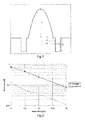
- Figure 2 graphically depicts bending losses as a function of bending radius (i.e ., radius of curvature) for an exemplary trench-assisted optical fiber according to the present invention (i.e ., Example 2) and a comparative optical fiber in accordance with the ITU-T G.651.1 recommendations ( i.e ., Example 1).
- Figure 3 graphically depicts bending losses as a function of bending radius (i.e ., radius of curvature) for another exemplary trench-assisted optical fiber according to the present invention (i.e ., Example 4) and another comparative optical fiber under a given Encircled Flux Launch (EFL) ( i.e ., Example 3).
- EDL Encircled Flux Launch
- the Encircled Flux (EF) in the optical fibers before bending fulfills the following criteria of Table 3: Table 3 radius ( ⁇ m) EF min EF max 10 0.2185 0.0635 15 0.38 0.2215 20 0.5249 0.4999
- the conditions on the EF for macrobending loss measurements are given by the ITU-T G.651.1 recommendations and the EF templates within the IEC 61280-4-1 documents.
- the comparative optical (Examples 1 and 3) and the exemplary optical fibers (Examples 2 and 4) of Figures 2 and 3 correspond to optical fibers having the parameters listed in Table 4.
- Table 4 Examples a ( ⁇ m) NA Trench width ( ⁇ m) Trench depth (x10 -3 ) Bending losses 2 turns 5 mm (dB) 1 31.25 0.27 none none 0.739 2 31.25 0.27 4 -8 0.138 3 41 0.31 none none none 1.060 4 41 0.31 4 -8 0.253
- Examples 2 and 4 are optical fibers according to the present invention that have a depressed trench of an appropriate width (i.e ., r 3 -r 2 ) and depth ( i.e ., ⁇ n 3 ).
- Examples 1 and 3 are comparative optical fibers lacking a depressed trench. The bending losses are measured at a wavelength of 850 nanometers.
- the depressed trench facilitates the achievement of reduced bending losses.
- the exemplary optical fibers exhibited bending losses that were more than four times less than the bending losses of the comparative optical fibers ( i.e ., a reduction to less than one-quarter of the comparative optical fibers' bending losses).
- Exemplary optical fibers according to the present invention include depressed trenches having particular volumes V 3 .
- this equation can be used for both rectangular and non-rectangular trenches.
- a depressed trench has a rectangular shape (i.e ., a step index profile)
- exemplary optical fibers include a depressed trench having a volume V 3 of between about -1710 %- ⁇ m 2 and -210 %- ⁇ m 2 ( e.g ., a volume V 3 of about -830 %- ⁇ m 2 ).
- the depressed trench's volume V 3 is about -790 %- ⁇ m 2 or greater ( e.g ., a volume V 3 of about -750 %- ⁇ m 2 or greater). More typically, the depressed trench's volume V 3 is about -710 %- ⁇ m 2 or greater ( e.g ., a volume V 3 of about -670 %- ⁇ m 2 or greater, such as about -635 %- ⁇ m 2 or greater).
- the depressed trench's volume V 3 is between about -750 %- ⁇ m 2 and - 450 %- ⁇ m 2 ( e.g ., between about -628 %- ⁇ m 2 and -565 %- ⁇ m 2 , such as about -600 %- ⁇ m 2 ).
- An optical-fiber cable that includes one more optical fibers in accordance with the present invention may be subjected to a pinch test as depicted in Figure 4 .
- the optical-fiber cable is folded over itself so that the two cable portions on either side of the fold are substantially parallel to one another, thereby creating a pinch in the optical-fiber cable.
- the resulting folded cable has a maximum diameter of about twice the cable's normal diameter.
- the optical-fiber cable is flattened and has a diameter less than its normal diameter.
- the optical-fiber cable has a reduced diameter at and near the pinch point, the remainder of the cable retains its normal diameter.
- the cable is held in this pinched state for about 10 minutes. After 10 minutes have elapsed and while the cable is held in the pinched state, the attenuation of the optical fibers in the cable is measured ( e.g ., at room temperature).
- exemplary multimode optical fibers accordance with the present invention typically have attenuation added losses of less than about 0.5 dB, more typically less than about 0.3 dB ( e.g ., less than about 0.25 dB, such as less than 0.20 dB).
- Exemplary optical-fiber cables capable of excellent pinch-test performance are disclosed in commonly assigned U.S. Patent Application Ser. No. 13/401,026 for an Optical Fiber Interconnect Cable.
- the present optical fibers may facilitate the reduction in overall optical-fiber diameter.
- a reduced-diameter optical fiber is cost-effective, requiring less raw material.
- a reduced-diameter optical fiber requires less deployment space (e.g ., within a buffer tube and/or fiber optic cable), thereby facilitating increased fiber count and/or reduced cable size.
- an optical fiber with a primary coating typically has an outer diameter of between about 235 microns and about 265 microns ( ⁇ m).
- the component glass fiber itself i.e ., the glass core and surrounding cladding layers
- the component glass fiber typically has an outer diameter of about 125 microns.
- the primary coating typically has an outer diameter of between about 175 microns and about 195 microns (i.e ., a primary coating thickness of between about 25 microns and 35 microns)
- the secondary coating typically has an outer diameter of between about 235 microns and about 265 microns ( i.e ., a secondary coating thickness of between about 20 microns and 45 microns).
- the present optical fiber may include an outermost ink layer, which is typically between two and ten microns in thickness.
- an optical fiber may possess a reduced diameter (e.g ., an outermost diameter between about 150 microns and 230 microns).
- the thickness of the primary coating and/or secondary coating is reduced, while the diameter of the component glass fiber is maintained at about 125 microns.
- the primary coating layer may have an outer diameter of between about 135 microns and about 175 microns ( e.g ., about 160 microns), typically less than 165 microns ( e.g ., between about 135 microns and 150 microns), and usually more than 140 microns ( e.g ., between about 145 microns and 155 microns, such as about 150 microns).
- the secondary coating layer may have an outer diameter of between about 150 microns and about 230 microns (e.g ., more than about 165 microns, such as 190-210 microns or so), typically between about 180 microns and 200 microns.
- the total diameter of the optical fiber is reduced to less than about 230 microns ( e.g ., between about 195 microns and 205 microns, and especially about 200 microns).
- an optical fiber may employ a secondary coating of about 197 microns at a tolerance of +/- 5 microns ( i.e ., a secondary-coating outer diameter of between 192 microns to 202 microns).
- the secondary coating will retain a thickness of at least about 10 microns (e.g ., an optical fiber having a reduced thickness secondary coating of between 15 microns and 25 microns).
- the outer diameter of the component glass fiber may be reduced to less than 125 microns (e.g ., between about 60 microns and 120 microns), perhaps between about 70 microns and 115 microns ( e.g ., about 80-110 microns). This may be achieved, for instance, by reducing the thickness of one or more cladding layers.
- the total diameter of the optical fiber may be reduced ( i.e ., the thickness of the primary and secondary coatings are maintained in accordance with the prior alternative embodiment) or ( ii ) the respective thicknesses of the primary and/or secondary coatings may be increased relative to the prior alternative embodiment ( e.g ., such that the total diameter of the optical fiber might be maintained).
- a component glass fiber having a diameter of between about 90 and 100 microns might be combined with a primary coating layer having an outer diameter of between about 110 microns and 150 microns ( e.g ., about 125 microns) and a secondary coating layer having an outer diameter of between about 130 microns and 190 microns ( e.g ., about 155 microns).
- a component glass fiber having a diameter of between about 90 and 100 microns might be combined with a primary coating layer having an outer diameter of between about 120 microns and 140 microns ( e.g ., about 130 microns) and a secondary coating layer having an outer diameter of between about 160 microns and 230 microns ( e.g ., about 195-200 microns).
- the present optical fibers may include one or more coating layers (e.g ., a primary coating and a secondary coating). At least one of the coating layers - typically the secondary coating - may be colored and/or possess other markings to help identify individual fibers. Alternatively, a tertiary ink layer may surround the primary and secondary coatings.
- a coating layer e.g ., a primary coating and a secondary coating. At least one of the coating layers - typically the secondary coating - may be colored and/or possess other markings to help identify individual fibers. Alternatively, a tertiary ink layer may surround the primary and secondary coatings.
Abstract
Description
- The present invention relates to the field of fiber optic transmission and, more specifically, to a multimode optical fiber having reduced bending losses.
- An optical fiber (i.e., a glass fiber typically surrounded by one or more coating layers) conventionally includes an optical fiber core, which transmits and/or amplifies an optical signal, and an optical cladding, which confines the optical signal within the core. Accordingly, the refractive index of the core nc is typically greater than the refractive index of the optical cladding ng (i.e., nc > ng).
- Multimode optical fibers are commonly used for short-distance applications requiring a broad bandwidth, such as local networks or LAN (local area network). The core of a multimode optical fiber typically has a diameter of between about 50 microns and 62.5 microns, whereas the core of a single-mode optical fiber typically has a diameter of between about 6 microns and 9 microns. In a multimode optical fiber, for a given wavelength, several optical modes are propagated simultaneously along the optical fiber.
- Multimode optical fibers have been the subject of international standardization under the ITU-T G.651.1 recommendations (July 2007), which, in particular, define criteria (e.g., bandwidth, numerical aperture, and core diameter) that relate to the requirements for optical fiber compatibility.
- The numerical aperture (NA) of an optical fiber can be approximated by the following equation:

where nc is the refractive index of the central core and ng is the refractive index of the outer cladding (e.g., an outer optical cladding). - For optical fibers, the refractive index profile is generally classified according to the graphical appearance of the function that associates the refractive index with the radius of the optical fiber. Conventionally, the distance r to the center of the optical fiber is shown on the x-axis, and the difference between the refractive index (at radius r) and the refractive index of the optical fiber's outer cladding (e.g., an outer optical cladding) is shown on the y-axis. The refractive index profile is referred to as a "step" profile, "trapezoidal" profile, "parabolic" profile, or "triangular" profile for graphs having the respective shapes of a step, a trapezoid, a parabola, or a triangle. These curves are generally representative of the optical fiber's theoretical or set profile. Constraints in the manufacture of the optical fiber, however, may result in a slightly different actual profile.
- For the same propagation medium (i.e., in a step-index multimode optical fiber), the different modes have different group delay times. This difference in group delay times results in a time lag (i.e., a delay) between the pulses propagating along different radial offsets of the optical fiber. This delay causes a broadening of the resulting light pulse. Broadening of the light pulse increases the risk of the pulse being superimposed onto a trailing pulse, which reduces the bandwidth (i.e., data rate) supported by the optical fiber. The bandwidth, therefore, is linked to the group delay time of the optical modes propagating in the multimode core of the optical fiber. Thus, to guarantee a broad bandwidth, it is desirable for the group delay times of all the modes to be identical. Stated differently, the intermodal dispersion should be zero, or at least minimized, for a given wavelength.
- To reduce intermodal dispersion, the multimode optical fibers used in telecommunications generally have a core with a refractive index that decreases progressively from the center of the optical fiber to its interface with a cladding (i.e., an "alpha" core profile). Such an optical fiber has been used for a number of years, and its characteristics have been described in "Multimode Theory of Graded-Core Fibers" by D. Gloge et al., Bell system Technical Journal 1973, pp. 1563-1578, and summarized in "Comprehensive Theory of Dispersion in Graded-Index Optical Fibers" by G. Yabre, Journal of Lightwave Technology, February 2000, Vol. 18, No. 2, pp. 166-177.
- A graded-index profile (i.e., an alpha-index profile) can be described by a relationship between the refractive index value n and the distance r from the center of the optical fiber according to the following equation:

α ≥ 1, and α is a non-dimensional parameter that is indicative of the shape of the index profile;
n1 is the maximum refractive index of the optical fiber's core;
a is the radius of the optical fiber's core; and
where no is the minimum refractive index of the multimode core, which may correspond to the refractive index of the outer cladding (most often made of silica). - A multimode optical fiber with a graded index (i.e., an alpha profile) therefore has a core profile with a rotational symmetry such that along any radial direction of the optical fiber the value of the refractive index decreases continuously from the center of the optical fiber's core to its periphery. When a multimode light signal propagates in such a graded-index core, the different optical modes experience differing propagation mediums (i.e., because of the varying refractive indices). This, in turn, affects the propagation speed of each optical mode differently. Thus, by adjusting the value of the parameter α, it is possible to obtain a group delay time that is virtually equal for all of the modes. Stated differently, the refractive index profile can be modified to reduce or even eliminate intermodal dispersion.
- Typically, multimode optical fibers with higher numerical apertures have lower macrobending losses (referred to hereafter as "bending losses").
- Conventional multimode optical fibers having a central core diameter of more than 50 microns are generally expected to provide sufficient bend resistance for many applications. Such exemplary optical fibers may have a central core diameter of 62.5 microns and a numerical aperture of 0.275 or a central core diameter of 80 microns and a numerical aperture of 0.3.
- Nevertheless, for tighter bend radii (e.g., 5 millimeters), such optical fibers exhibit significant bending losses that may be critical for high speed transmission (e.g., in compact consumer electronic devices).
- International Publication No.
WO 2010/036684 deals with large-core optical fibers. The disclosed optical fibers, however, have a central-core radius a and a relative refractive index difference Δ such that:
- The central cores of the disclosed optical fibers fail to provide reduced microbending losses, because, for a given Δ value, enlarging the central core will result in larger microbending losses. Furthermore, the relationships between the disclosed central-core radius a and the relative refractive index difference Δ lead to undesirably large microbending losses.
- Therefore, a need exists for a multimode optical fiber having reduced bending losses and a central-core diameter of greater than 50 microns.
- In a first aspect, the present invention relates to a multimode optical fiber, comprising:
- * a central core surrounded by an outer optical cladding having a refractive index value ncl, said central core having (i) an outer radius r1 of about 35 microns or greater, (ii) a maximum refractive index value no, (iii) a graded-index profile with respect to said outer optical cladding, and (iv) a relative refractive index difference:

- * an inner cladding positioned between said central core and said outer cladding, said inner cladding having an outer radius r2; and
- * a depressed trench positioned between said inner cladding and said outer optical cladding, said depressed trench having an outer radius r3, a refractive index difference Δn3 with respect to said outer optical cladding, and a volume V3;
- * wherein

- According to another embodiment of said first aspect,

- According to yet another embodiment of said first aspect, said depressed trench's volume V3 is -635 %-µm2 or greater.
- According to yet another embodiment of said first aspect, said central core's outer radius r1 is 36 microns or greater; and said depressed trench's volume V3 is -670 %-µm2 or greater.
- According to yet another embodiment of said first aspect, said central core's outer radius r1 is 37 microns or greater; and

- According to yet another embodiment of said first aspect, said central core's outer radius r1 is 38 microns or greater; and said depressed trench's volume V3 is -750 %-µm2 or greater.
- According to yet another embodiment of said first aspect, said central core's outer radius r1 is 39 microns or greater; and

- According to yet another embodiment of said first aspect, said central core's outer radius r1 is 39 microns or greater; and said depressed trench's volume V3 is -790 %-µm2 or greater.
- According to yet another embodiment of said first aspect, said central core's outer radius r1 is 40 microns or greater.
- In a second aspect, the present invention relates to a multimode optical fiber, comprising:
- * a central core surrounded by an outer optical cladding having a refractive index value ncl, said central core having (i) an outer radius r1 of between about 35 microns and 50 microns, (ii) a maximum refractive index value no, (iii) a graded-index profile with respect to said outer optical cladding, and (iv) a relative refractive index difference:

- * an inner cladding positioned between said central core and said outer cladding, said inner cladding having an outer radius r2; and
- * a depressed trench positioned between said inner cladding and said outer optical cladding, said depressed trench having an outer radius r3, a refractive index difference Δn3 with respect to said outer optical cladding of between about -10x10-3 and -5x10⁻³, and a volume V3;
- * wherein

- * wherein the difference r2-r1 between said inner cladding's outer radius r2 and said central core's outer radius r1 is between about 1 micron and 3 microns;
- * wherein the difference r3-r2 between said depressed trench's outer radius r3 and said inner cladding's outer radius r2 is between about 3 microns and 7 microns; and
- * wherein, for two turns around a radius of curvature of 5 millimeters at a wavelength of 850 nanometers, the optical fiber has bending losses of less than about 0.3 dB.
- According to another yet embodiment of said second aspect,

- According to another yet embodiment of said second aspect,

- According to another yet embodiment of said second aspect, said central core's outer radius r1 is 36 microns or greater; and

- According to another yet embodiment of said second aspect, said central core's outer radius r1 is 37 microns or greater; and said depressed trench's volume V3 is -710 %-µm2 or greater.
- According to another yet embodiment of said second aspect, said central core's outer radius r1 is 38 microns or greater; and

- According to another yet embodiment of said second aspect, said central core's outer radius r1 is between about 39 microns and 41 microns.
- According to another yet embodiment of said second aspect, said depressed trench's volume V3 is -650 %-µm2 or greater.
- According to another yet embodiment of said second aspect, said central core's outer radius r1 is 40 microns or greater; and said depressed trench's volume V3 is -830 %-µm2 or greater.
- According to another yet embodiment of said second aspect, the difference r2-r1 between said inner cladding's outer radius r2 and said central core's outer radius r1 is less than 2 microns.
- According to another yet embodiment of said second aspect, the difference r3-r2 between said depressed trench's outer radius r3 and said inner cladding's outer radius r2 is less than 5 microns.
- According to another yet embodiment of said second aspect, for two turns around a radius of curvature of 5 millimeters at a wavelength of 850 nanometers, the optical fiber has bending losses of less than about 0.2 dB.
- In a third aspect, the present invention relates to an optical system comprising the optical fiber according to the second aspect of the present invention.
- Accordingly, in one aspect, the present invention embraces an optical fiber that includes a central core surrounded by an outer cladding (e.g., an outer optical cladding). The outer cladding has a refractive index value ncl. The central core has an outer radius r1, a maximum refractive index value no, and a graded-index profile with respect to the outer cladding. The central core also has a relative refractive index difference:

- The central core's outer radius r1 is typically between about 30 microns and 50 microns (e.g., 35 microns to 50 microns). Typically, the central core's outer radius r1 and relative refractive index difference Δ satisfy the following inequality:

- An inner cladding is positioned between the central core and the outer cladding (e.g., immediately surrounding the central core). The inner cladding has an outer radius r2 and a refractive index difference Δn2 with respect to the outer cladding. Typically, the difference r2-r1 between the inner cladding's outer radius r2 and the central core's outer radius r1 is between about 1 micron and 3 microns.
- A depressed trench is positioned between the inner cladding and the outer cladding (e.g., immediately surrounding the inner cladding). The depressed trench has an outer radius r3 and a negative refractive index difference Δn3 with respect to the outer cladding. Typically, the difference r3-r2 between the depressed trench's outer radius r3 and the inner cladding's outer radius r2 is between about 3 microns and 7 microns. The depressed trench's refractive index difference Δn3 is typically between about -10x10-3 and -5x10⁻³.
- In an exemplary embodiment, for two turns around a radius of curvature of 5 millimeters at a wavelength of 850 nanometers, the optical fiber has bending losses of less than about 0.3 dB.
- In another exemplary embodiment, for two turns around a radius of curvature of 5 millimeters at a wavelength of 850 nanometers, the optical fiber has bending losses of less than about 0.2 dB.
- In yet another exemplary embodiment, the central core's outer radius r1 and relative refractive index difference Δ satisfy the following inequality:

- In yet another exemplary embodiment, the central core's outer radius r1 is between about 35 microns and 50 microns (e.g., between about 35 microns and 45 microns).
- In yet another exemplary embodiment, the central core's outer radius r1 is greater than about 36 microns (e.g., about 37 microns or greater).
- In yet another exemplary embodiment, the central core's outer radius r1 is greater than about 38 microns (e.g., between about 39 microns and 41 microns).
- In yet another exemplary embodiment, the central core's outer diameter (i.e., 2r1) is about 62.5 microns.
- In yet another exemplary embodiment, the central core's outer diameter (i.e., 2r1) is about 80 microns (i.e., outer radius r1 is about 40 microns).
- In another aspect, the present invention embraces a multimode optical system that includes an optical fiber in accordance with the foregoing.
- The foregoing illustrative summary, as well as other exemplary objectives and/or advantages of the invention, and the manner in which the same are accomplished, are further explained within the following detailed description and its accompanying drawings.
-
- Figure 1
- graphically depicts the refractive index profile of an exemplary optical fiber according to the present invention.
- Figure 2
- graphically depicts bending losses as a function of bending radius (i.e., radius of curvature) for an exemplary optical fiber according to the present invention and a comparative optical fiber.
- Figure 3
- graphically depicts bending losses as a function of bending radius (i.e., radius of curvature) for another exemplary optical fiber according to the present invention and another comparative optical fiber.
- Figure 4
- depicts an optical-fiber cable undergoing a pinch test.
- The present invention relates to a multimode optical fiber, comprising: a central core surrounded by an outer optical cladding having a refractive index value ncl, said central core having (i) an outer radius r1 of about 35 microns or greater, (ii) a maximum refractive index value n0, (iii) a graded-index profile with respect to said outer optical cladding, and (iv) a relative refractive index difference:


- In embodiments of the present invention:
- •

- • the central core's outer radius r1 is equal to or lower than 50 microns;
- • the central core's outer radius r1 is 36 microns or greater, preferably 37 microns or greater, more preferably 38 microns or greater, even more preferably 39 microns or greater, even more preferably 40 microns or greater, most preferably between about 39 microns and 41 microns;
- • said depressed trench's volume V3 is -650 %-µm2 or greater, preferably V3 is -670 %-um2 or greater, preferably V3 is -710 %-µm2 or greater, more preferably V3 is -750 %-µm2 or greater, even more preferably V3 is -790 %-µm2 or greater, even more preferably V3 is -830 %-µm2 or greater;
- • the difference r2-r1 between said inner cladding's outer radius r2 and said central core's outer radius r1 is between about 1 micron and 3 microns, preferably equal to or lower than 2 micron;
- • the difference r3-r2 between said depressed trench's outer radius r3 and said inner cladding's outer radius r2 is between about 3 microns and 7 microns, preferably equal to or lower than 5 microns;
- • the refractive index difference Δn3 with respect to said outer optical cladding of between about -10x10-3 and -5x10⁻³;
- • for two turns around a radius of curvature of 5 millimeters at a wavelength of 850 nanometers, the optical fiber has bending losses of less than about 0.3 dB, preferably less than about 0.2 dB.
- Moreover, the invention relates to a multimode optical fiber, comprising: a central core surrounded by an outer optical cladding having a refractive index value ncl, said central core having (i) an outer radius r1 of between about 35 microns and 50 microns, (ii) a maximum refractive index value n0, (iii) a graded-index profile with respect to said outer optical cladding, and (iv) a relative refractive index difference:
-


- Moreover, the invention relates to an optical system comprising the optical fiber according to the present invention.
- The present invention embraces a multimode optical fiber having reduced bending losses and a central-core diameter of greater than 50 microns.
-
Figure 1 depicts the refractive index profile of an exemplary optical fiber in accordance with the present invention. The exemplary optical fiber is a multimode optical fiber that includes a central core (e.g., an inner core) surrounded by an outer cladding (e.g., an outer optical cladding). - As depicted, the exemplary optical fiber also includes an inner cladding positioned between the central core and the outer cladding (e.g., immediately surrounding the central core). A depressed trench is positioned between the inner cladding and the outer optical cladding (e.g., immediately surrounding the inner cladding).
- The central core has an outer radius r1 that is typically between 30 microns and 50 microns, more typically 35 microns or greater (e.g., between about 39 microns and 41 microns). The central core also has a graded-index profile relative to the outer cladding. The central core's outer radius r1 and relative refractive index difference Δ typically satisfy the following inequality:

- The central core's relative refractive index difference Δ is defined by the following equation:

where no is the maximum refractive index value of the central core (typically corresponding to the refractive index value of the center of the central core) and ncl is the refractive index value of the outer cladding. - The optical fiber's inner cladding has an outer radius r2. Typically, the difference r2-r1 between the inner cladding's outer radius r2 and the central core's outer radius r1 (e.g., the radial distance between the central core's outer radius and the inner radius of the depressed trench) is between 1 micron and 3 microns (e.g., about 2 microns or less).
- The depressed trench has an outer radius r3 and a negative refractive index difference Δn3 with respect to the outer cladding. Typically, the difference r3-r2 between the depressed trench's outer radius r3 and the inner cladding's outer radius r2 (e.g., the width of the depressed trench) is between 3 microns and 7 microns (e.g., about 5 microns or less, such as about 4 microns). The depressed trench's refractive index difference Δn3 (e.g., the depth of the depressed trench) is typically between - 10x10-3 and -5x10⁻³.
- The present multimode optical fiber provides excellent macrobending performance. For example, for two turns around a radius of curvature of 5 millimeters at a wavelength of 850 nanometers, the optical fiber typically has bending losses of less than 0.3 dB (e.g., less than 0.2 dB). In another exemplary embodiment, for one turn around a radius of curvature of 3 millimeters at a wavelength of 850 nanometers, the optical fiber has bending losses of less than about 0.5 dB.
- Exemplary multimode optical fibers in accordance with the present invention include a central core having an outer diameter of 62.5 microns (i.e., 62.5-micron MMFs) and exhibit improved bend resistance. Additionally, exemplary multimode optical fibers include a central core having an outer diameter of 80 microns (i.e., 80-micron MMFs) and exhibit improved bend resistance.
- As noted, exemplary multimode optical fibers include a central core having a graded-index profile relative to the outer cladding (i.e., Graded-Index MultiMode Fibers or GI-MMFs). The modal structure of GI-MMFs is as follows.
- In multimode optical fibers with the following refractive index profile:

where α is between about 1.9 and 2.1, Δ > 1.2 percent and a > 30 microns, the effective indices of the guided modes can be fairly approximated as follows:
where m is the order of the mode, and
where
- For α approximately equal to 2, the spacing between modes is somewhat independent from the mode order m and is only a function of the central core's radius a and the central core's height Δ:

- For a 50-micron GI-MMF with Δ = 0.9 percent and a = 26 microns (as a threshold) this mode spacing (i.e., Δβ) is equal to 5.1x10⁻³ µm-1. Acceptable tolerances with respect to core diameter (e.g., ±2.5 microns) and numerical aperture (e.g., ± 0.015) may be taken into account in view of constraints in the manufacturing process.
- Without being bound to any particular theory, the present inventors have found that mode spacing affects microbending losses. Indeed, considering the three examples of Table 1, larger values of

Table 1 Δ (%) r1 (µm) Criterion (µm-1) Microbending losses @ 850nm (dB/km) Primary coating thickness (µm) 1.928 38.8 5.06×10⁻³ 27.5 27.935 2.059 39.2 5.18×10⁻³ 20.3 27.93 2.601 38.4 5.94×10⁻³ 12.1 27.75 - As shown in Table 1, an increase in the criterion from 5.06x10⁻³ to 5.94x10⁻³ reduces microbending losses two-fold. Accordingly, exemplary optical fibers in accordance with the present invention have a central-core outer radius r1 and relative refractive index difference Δ such that


- Microbending may be analyzed according to the IEC fixed-diameter sandpaper drum test (i.e., IEC TR62221, Method B, 40-micron grade sandpaper), which provides a microbending stress situation that affects multimode fibers even at room temperature. The IEC TR62221 microbending-sensitivity technical report and standard test procedures, includes i.a. IEC TR62221, Method B (fixed-diameter sandpaper drum) and Method D (basketweave).
- To satisfy the foregoing relationship between the central core's outer radius r1 and relative refractive index difference Δ, larger central-core radii demand larger values for Δ, as illustrated in Table 2. In Table 2, the relative refractive index difference Δ is given as a percentage.
Table 2 a (µm) Δ (%) NA 25 > 0.81 > 0.185 31.25 > 1.27 > 0.232 40 > 2.08 > 0.297 50 > 3.25 > 0.373 - Typically, macro-bending losses are lower for optical fibers with such large numerical apertures. Furthermore, as illustrated in
Figures 2 and3 , including a depressed trench between the central core and the outer cladding further improves the macro-bending behavior of these large core radii MMFs. -
Figure 2 graphically depicts bending losses as a function of bending radius (i.e., radius of curvature) for an exemplary trench-assisted optical fiber according to the present invention (i.e., Example 2) and a comparative optical fiber in accordance with the ITU-T G.651.1 recommendations (i.e., Example 1). -
Figure 3 graphically depicts bending losses as a function of bending radius (i.e., radius of curvature) for another exemplary trench-assisted optical fiber according to the present invention (i.e., Example 4) and another comparative optical fiber under a given Encircled Flux Launch (EFL) (i.e., Example 3). - The Encircled Flux (EF) in the optical fibers before bending fulfills the following criteria of Table 3:
Table 3 radius (µm) EF min EF max 10 0.2185 0.0635 15 0.38 0.2215 20 0.5249 0.4999 - For 62.5-micron and 50-micron MFFs, the conditions on the EF for macrobending loss measurements are given by the ITU-T G.651.1 recommendations and the EF templates within the IEC 61280-4-1 documents.
- The comparative optical (Examples 1 and 3) and the exemplary optical fibers (Examples 2 and 4) of
Figures 2 and3 correspond to optical fibers having the parameters listed in Table 4.Table 4 Examples a (µm) NA Trench width (µm) Trench depth (x10-3) Bending losses 2turns 5 mm (dB)1 31.25 0.27 none none 0.739 2 31.25 0.27 4 -8 0.138 3 41 0.31 none none 1.060 4 41 0.31 4 -8 0.253 - As noted, Examples 2 and 4 are optical fibers according to the present invention that have a depressed trench of an appropriate width (i.e., r3-r2) and depth (i.e., Δn3). Examples 1 and 3 are comparative optical fibers lacking a depressed trench. The bending losses are measured at a wavelength of 850 nanometers.
- As demonstrated by Table 4 and depicted in
Figures 2 and3 , the depressed trench facilitates the achievement of reduced bending losses. Indeed, the exemplary optical fibers exhibited bending losses that were more than four times less than the bending losses of the comparative optical fibers (i.e., a reduction to less than one-quarter of the comparative optical fibers' bending losses). - Advantages of large-core optical fibers having reduced bending losses are further described in "80µm-core graded-index MMF for consumer electronic devices" by D. Molin, M. Bigot-Astruc, and P. Sillard, Optoelectronic Interconnects XII, February 2, 2012, Proceedings of SPIE Vol. 8267.
- Exemplary optical fibers according to the present invention include depressed trenches having particular volumes V3. As used herein, the volume V of a depressed trench is defined by the following equation:

in which rint and rext are the inner radius and outer radius of the depressed trench, respectively, and Δ%(r) is the depressed trench's refractive index difference with respect to the outer cladding expressed in terms of percentage. Those of ordinary skill in the art will recognize that this equation can be used for both rectangular and non-rectangular trenches. - If a depressed trench has a rectangular shape (i.e., a step index profile), the equation (above) can be simplified to the following equation:

in which rext and rint are the outer radius and inner radius of the depressed trench, respectively, and Δ% is the depressed trench's refractive index difference with respect to the outer cladding expressed as a percentage. - In this regard, exemplary optical fibers include a depressed trench having a volume V3 of between about -1710 %-µm2 and -210 %-µm2 (e.g., a volume V3 of about -830 %-µm2). Typically, the depressed trench's volume V3 is about -790 %-µm2 or greater (e.g., a volume V3 of about -750 %-µm2 or greater). More typically, the depressed trench's volume V3 is about -710 %-µm2 or greater (e.g., a volume V3 of about -670 %-µm2 or greater, such as about -635 %-µm2 or greater). In exemplary embodiments, the depressed trench's volume V3 is between about -750 %-µm2 and - 450 %-µm2 (e.g., between about -628 %-µm2 and -565 %-µm2, such as about -600 %-µm2).
- An optical-fiber cable that includes one more optical fibers in accordance with the present invention may be subjected to a pinch test as depicted in
Figure 4 . During the pinch test the optical-fiber cable is folded over itself so that the two cable portions on either side of the fold are substantially parallel to one another, thereby creating a pinch in the optical-fiber cable. The resulting folded cable has a maximum diameter of about twice the cable's normal diameter. At the pinch point, the optical-fiber cable is flattened and has a diameter less than its normal diameter. Although the optical-fiber cable has a reduced diameter at and near the pinch point, the remainder of the cable retains its normal diameter. The cable is held in this pinched state for about 10 minutes. After 10 minutes have elapsed and while the cable is held in the pinched state, the attenuation of the optical fibers in the cable is measured (e.g., at room temperature). - During a pinch test at 850 nm, exemplary multimode optical fibers accordance with the present invention (and contained within an optical-fiber cable) typically have attenuation added losses of less than about 0.5 dB, more typically less than about 0.3 dB (e.g., less than about 0.25 dB, such as less than 0.20 dB).
- Exemplary optical-fiber cables capable of excellent pinch-test performance are disclosed in commonly assigned
U.S. Patent Application Ser. No. 13/401,026 for an Optical Fiber Interconnect Cable. - The present optical fibers may facilitate the reduction in overall optical-fiber diameter. As will be appreciated by those having ordinary skill in the art, a reduced-diameter optical fiber is cost-effective, requiring less raw material. Moreover, a reduced-diameter optical fiber requires less deployment space (e.g., within a buffer tube and/or fiber optic cable), thereby facilitating increased fiber count and/or reduced cable size.
- Those having ordinary skill in the art will recognize that an optical fiber with a primary coating (and an optional secondary coating and/or ink layer) typically has an outer diameter of between about 235 microns and about 265 microns (µm). The component glass fiber itself (i.e., the glass core and surrounding cladding layers) typically has a diameter of about 125 microns, such that the total coating thickness is typically between about 55 microns and 70 microns.
- With respect to the present optical fiber, the component glass fiber typically has an outer diameter of about 125 microns. With respect to the optical fiber's surrounding coating layers, the primary coating typically has an outer diameter of between about 175 microns and about 195 microns (i.e., a primary coating thickness of between about 25 microns and 35 microns), and the secondary coating typically has an outer diameter of between about 235 microns and about 265 microns (i.e., a secondary coating thickness of between about 20 microns and 45 microns). Optionally, the present optical fiber may include an outermost ink layer, which is typically between two and ten microns in thickness.
- In one alternative embodiment, an optical fiber may possess a reduced diameter (e.g., an outermost diameter between about 150 microns and 230 microns). In this alternative optical fiber configuration, the thickness of the primary coating and/or secondary coating is reduced, while the diameter of the component glass fiber is maintained at about 125 microns. (Those having ordinary skill in the art will appreciate that, unless otherwise specified, diameter measurements refer to outer diameters.)
- By way of illustration, in such exemplary embodiments, the primary coating layer may have an outer diameter of between about 135 microns and about 175 microns (e.g., about 160 microns), typically less than 165 microns (e.g., between about 135 microns and 150 microns), and usually more than 140 microns (e.g., between about 145 microns and 155 microns, such as about 150 microns).
- Moreover, in such exemplary embodiments, the secondary coating layer may have an outer diameter of between about 150 microns and about 230 microns (e.g., more than about 165 microns, such as 190-210 microns or so), typically between about 180 microns and 200 microns. In other words, the total diameter of the optical fiber is reduced to less than about 230 microns (e.g., between about 195 microns and 205 microns, and especially about 200 microns). By way of further illustration, an optical fiber may employ a secondary coating of about 197 microns at a tolerance of +/- 5 microns (i.e., a secondary-coating outer diameter of between 192 microns to 202 microns). Typically, the secondary coating will retain a thickness of at least about 10 microns (e.g., an optical fiber having a reduced thickness secondary coating of between 15 microns and 25 microns).
- In another alternative embodiment, the outer diameter of the component glass fiber may be reduced to less than 125 microns (e.g., between about 60 microns and 120 microns), perhaps between about 70 microns and 115 microns (e.g., about 80-110 microns). This may be achieved, for instance, by reducing the thickness of one or more cladding layers. As compared with the prior alternative embodiment, (i) the total diameter of the optical fiber may be reduced (i.e., the thickness of the primary and secondary coatings are maintained in accordance with the prior alternative embodiment) or (ii) the respective thicknesses of the primary and/or secondary coatings may be increased relative to the prior alternative embodiment (e.g., such that the total diameter of the optical fiber might be maintained).
- By way of illustration, with respect to the former, a component glass fiber having a diameter of between about 90 and 100 microns might be combined with a primary coating layer having an outer diameter of between about 110 microns and 150 microns (e.g., about 125 microns) and a secondary coating layer having an outer diameter of between about 130 microns and 190 microns (e.g., about 155 microns). With respect to the latter, a component glass fiber having a diameter of between about 90 and 100 microns might be combined with a primary coating layer having an outer diameter of between about 120 microns and 140 microns (e.g., about 130 microns) and a secondary coating layer having an outer diameter of between about 160 microns and 230 microns (e.g., about 195-200 microns).
- Reducing the diameter of the component glass fiber might make the resulting optical fiber more susceptible to microbending attenuation. That said, the advantages of further reducing optical-fiber diameter might be worthwhile for some optical-fiber applications.
- As noted, the present optical fibers may include one or more coating layers (e.g., a primary coating and a secondary coating). At least one of the coating layers - typically the secondary coating - may be colored and/or possess other markings to help identify individual fibers. Alternatively, a tertiary ink layer may surround the primary and secondary coatings.
- In the specification and/or figures, typical embodiments of the invention have been disclosed. The present invention is not limited to such exemplary embodiments. The use of the term "and/or" includes any and all combinations of one or more of the associated listed items. The figures are schematic representations and so are not necessarily drawn to scale. Unless otherwise noted, specific terms have been used in a generic and descriptive sense and not for purposes of limitation.
Claims (11)
- A multimode optical fiber, comprising:* a central core surrounded by an outer optical cladding having a refractive index value ncl, said central core having (i) an outer radius r1 of about 35 microns or greater, (ii) a maximum refractive index value no, (iii) a graded-index profile with respect to said outer optical cladding, and (iv) a relative refractive index difference:
 * an inner cladding positioned between said central core and said outer cladding, said inner cladding having an outer radius r2; and* a depressed trench positioned between said inner cladding and said outer optical cladding, said depressed trench having an outer radius r3, a refractive index difference Δn3 with respect to said outer optical cladding, and a volume V3;* wherein
- Multimode optical fiber according to claim 1, wherein

- Multimode optical fiber according to any one of the preceding claims, wherein the central core's outer radius r1 is equal to or lower than 50 microns.
- Multimode optical fiber according to any one of the preceding claims, wherein the central core's outer radius r1 is 36 microns or greater, preferably 37 microns or greater, more preferably 38 microns or greater, even more preferably 39 microns or greater, even more preferably 40 microns or greater, most preferably between about 39 microns and 41 microns.
- Multimode optical fiber according to any one of the preceding claims, wherein said depressed trench's volume V3 is -650 %-µm2 or greater, preferably V3 is -670 %-µm2 or greater, preferably V3 is -710 %-µm2 or greater, more preferably V3 is -750 %-µm2 or greater, even more preferably V3 is -790 %-µm2 or greater, even more preferably V3 is -830 %-µm2 or greater.
- Multimode optical fiber according to any one of the preceding claims, wherein the difference r2-r1 between said inner cladding's outer radius r2 and said central core's outer radius r1 is between about 1 micron and 3 microns, preferably equal to or lower than 2 micron.
- Multimode optical fiber according to any one of the preceding claims, wherein the difference r3-r2 between said depressed trench's outer radius r3 and said inner cladding's outer radius r2 is between about 3 microns and 7 microns, preferably equal to or lower than 5 microns.
- Multimode optical fiber according to any one of the preceding claims, Wherein the refractive index difference Δn3 with respect to said outer optical cladding of between about -10x10-3 and -5x10⁻³.
- Multimode optical fiber according to any one of the preceding claims, wherein, for two turns around a radius of curvature of 5 millimeters at a wavelength of 850 nanometers, the optical fiber has bending losses of less than about 0.3 dB, preferably less than about 0.2 dB.
- A multimode optical fiber, comprising:* a central core surrounded by an outer optical cladding having a refractive index value ncl, said central core having (i) an outer radius r1 of between about 35 microns and 50 microns, (ii) a maximum refractive index value n0, (iii) a graded-index profile with respect to said outer optical cladding, and (iv) a relative refractive index difference:

 * an inner cladding positioned between said central core and said outer cladding, said inner cladding having an outer radius r2; wherein the difference r2-r1 between said inner cladding's outer radius r2 and said central core's outer radius r1 is between about 1 micron and 3 microns;* a depressed trench positioned between said inner cladding and said outer optical cladding, said depressed trench having an outer radius r3, a refractive index difference Δn3 with respect to said outer optical cladding of between about - 10x10-3 and -5x10⁻³, and a volume V3; wherein the difference r3-r2 between said depressed trench's outer radius r3 and said inner cladding's outer radius r2 is between about 3 microns and 7 microns; and wherein said depressed trench's volume V3 is -635 %-µm2 or greater.
wherein, for two turns around a radius of curvature of 5 millimeters at a wavelength of 850 nanometers, the optical fiber has bending losses of less than about 0.3 dB. - An optical system comprising the optical fiber according to any one of the preceding claims.
Applications Claiming Priority (1)
| Application Number | Priority Date | Filing Date | Title |
|---|---|---|---|
| US13/428,520 US9341771B2 (en) | 2011-03-24 | 2012-03-23 | Bend-resistant multimode optical fiber |
Publications (2)
| Publication Number | Publication Date |
|---|---|
| EP2642322A1 true EP2642322A1 (en) | 2013-09-25 |
| EP2642322B1 EP2642322B1 (en) | 2019-07-10 |
Family
ID=46022133
Family Applications (1)
| Application Number | Title | Priority Date | Filing Date |
|---|---|---|---|
| EP12166927.9A Active EP2642322B1 (en) | 2012-03-23 | 2012-05-07 | Bend-resistant multimode optical fiber |
Country Status (4)
| Country | Link |
|---|---|
| EP (1) | EP2642322B1 (en) |
| JP (1) | JP5945472B2 (en) |
| CN (1) | CN103323907B (en) |
| DK (1) | DK2642322T3 (en) |
Cited By (2)
| Publication number | Priority date | Publication date | Assignee | Title |
|---|---|---|---|---|
| US9341771B2 (en) | 2011-03-24 | 2016-05-17 | Draka Comteq, B.V. | Bend-resistant multimode optical fiber |
| WO2017200986A1 (en) * | 2016-05-17 | 2017-11-23 | Corning Incorporated | Optical fiber for both multimode and single-mode operation and transmission system therefor |
Families Citing this family (2)
| Publication number | Priority date | Publication date | Assignee | Title |
|---|---|---|---|---|
| WO2015128691A1 (en) * | 2014-02-28 | 2015-09-03 | Draka Comteq Bv | Multimode optical fiber with high bandwidth over an extended wavelength range, and corresponding multimode optical system. |
| JP2020140080A (en) * | 2019-02-28 | 2020-09-03 | 住友電気工業株式会社 | Optical fiber |
Citations (5)
| Publication number | Priority date | Publication date | Assignee | Title |
|---|---|---|---|---|
| EP2166386A1 (en) * | 2008-09-17 | 2010-03-24 | OFS Fitel, LLC | Bandwidth-maintaining multimode optical fibers |
| WO2010036684A2 (en) | 2008-09-26 | 2010-04-01 | Corning Incorporated | High numerical aperture multimode optical fiber |
| EP2333593A1 (en) * | 2009-11-25 | 2011-06-15 | Draka Comteq B.V. | High bandwidth multimode optical fiber |
| WO2011109263A1 (en) * | 2010-03-02 | 2011-09-09 | Corning Incorporated | High numerical aperture multimode optical fiber |
| EP2503368A1 (en) * | 2011-03-24 | 2012-09-26 | Draka Comteq B.V. | Multimode optical fiber with improved bend resistance |
Family Cites Families (3)
| Publication number | Priority date | Publication date | Assignee | Title |
|---|---|---|---|---|
| CN101861537A (en) * | 2007-11-19 | 2010-10-13 | 三菱电线工业株式会社 | Optical fiber and method for producing the same |
| US20090169163A1 (en) * | 2007-12-13 | 2009-07-02 | Abbott Iii John Steele | Bend Resistant Multimode Optical Fiber |
| US7903918B1 (en) * | 2010-02-22 | 2011-03-08 | Corning Incorporated | Large numerical aperture bend resistant multimode optical fiber |
-
2012
- 2012-05-07 DK DK12166927.9T patent/DK2642322T3/en active
- 2012-05-07 EP EP12166927.9A patent/EP2642322B1/en active Active
- 2012-07-20 JP JP2012161570A patent/JP5945472B2/en active Active
- 2012-08-06 CN CN201210277442.1A patent/CN103323907B/en active Active
Patent Citations (5)
| Publication number | Priority date | Publication date | Assignee | Title |
|---|---|---|---|---|
| EP2166386A1 (en) * | 2008-09-17 | 2010-03-24 | OFS Fitel, LLC | Bandwidth-maintaining multimode optical fibers |
| WO2010036684A2 (en) | 2008-09-26 | 2010-04-01 | Corning Incorporated | High numerical aperture multimode optical fiber |
| EP2333593A1 (en) * | 2009-11-25 | 2011-06-15 | Draka Comteq B.V. | High bandwidth multimode optical fiber |
| WO2011109263A1 (en) * | 2010-03-02 | 2011-09-09 | Corning Incorporated | High numerical aperture multimode optical fiber |
| EP2503368A1 (en) * | 2011-03-24 | 2012-09-26 | Draka Comteq B.V. | Multimode optical fiber with improved bend resistance |
Non-Patent Citations (3)
| Title |
|---|
| D. GLOGE ET AL.: "Multimode Theory of Graded-Core Fibers", BELL SYSTEM TECHNICAL JOURNAL, 1973, pages 1563 - 1578, XP011629356, DOI: doi:10.1002/j.1538-7305.1973.tb02033.x |
| D. MOLIN; M. BIGOT-ASTRUC; P. SILLARD: "80pm-core graded-index MMF for consumer electronic devices", OPTOELECTRONIC INTERCONNECTS XII, FEBRUARY 2, 2012, PROCEEDINGS OF SPIE, vol. 8267, 2 February 2012 (2012-02-02) |
| G. YABRE: "Comprehensive Theory of Dispersion in Graded-Index Optical Fibers", JOURNAL OF LIGHTWAVE TECHNOLOGY, vol. 18, no. 2, February 2000 (2000-02-01), pages 166 - 177, XP001001811, DOI: doi:10.1109/50.822789 |
Cited By (4)
| Publication number | Priority date | Publication date | Assignee | Title |
|---|---|---|---|---|
| US9341771B2 (en) | 2011-03-24 | 2016-05-17 | Draka Comteq, B.V. | Bend-resistant multimode optical fiber |
| US9671553B2 (en) | 2011-03-24 | 2017-06-06 | Draka Comteq, B.V. | Bend-resistant multimode optical fiber |
| WO2017200986A1 (en) * | 2016-05-17 | 2017-11-23 | Corning Incorporated | Optical fiber for both multimode and single-mode operation and transmission system therefor |
| US10295734B2 (en) | 2016-05-17 | 2019-05-21 | Corning Incorporated | Optical fiber for both multimode and single-mode operation and transmission system therefor |
Also Published As
| Publication number | Publication date |
|---|---|
| CN103323907A (en) | 2013-09-25 |
| CN103323907B (en) | 2018-01-23 |
| JP5945472B2 (en) | 2016-07-05 |
| JP2013200544A (en) | 2013-10-03 |
| DK2642322T3 (en) | 2019-08-05 |
| EP2642322B1 (en) | 2019-07-10 |
Similar Documents
| Publication | Publication Date | Title |
|---|---|---|
| EP2503368A1 (en) | Multimode optical fiber with improved bend resistance | |
| EP2299302B1 (en) | Multimode optical fibre having improved bending losses | |
| JP5804793B2 (en) | Single mode optical fiber and optical system | |
| EP2333594B1 (en) | High bandwidth multimode optical fiber | |
| EP2786185B1 (en) | Low bend loss optical fiber | |
| EP2352047B1 (en) | Non-zero dispersion shifted optical fiber having a large effective area | |
| EP2339383B1 (en) | Multimode optical fiber with low bending losses and reduced cladding effect | |
| EP2352046B1 (en) | Non-zero dispersion shifted optical fiber having a short cutoff wavelength | |
| EP2984509B1 (en) | Low bend loss optical fiber | |
| EP2539752B1 (en) | Low bend loss optical fiber | |
| JP6298893B2 (en) | Single mode fiber with trapezoidal core showing reduced loss | |
| EP2369379A1 (en) | Optical singlemode fibre with reduced bending losses | |
| JP5396468B2 (en) | Single mode optical fiber with holes and optical transmission system using the same | |
| US8787720B2 (en) | Optical fiber | |
| US9594212B2 (en) | Multimode optical fibers | |
| JP2011523721A (en) | Bending sensitivity and catastrophic bending loss reduction in single mode optical fibers and methods of fabrication | |
| KR20120083384A (en) | Low bend loss optical fiber | |
| KR20140088151A (en) | Ge-P Co-doped Multimode Optical Fiber | |
| US20170068046A1 (en) | Multimode optical fibers operating over an extended wavelength range and system incorporating such | |
| EP3014320B1 (en) | Bend-insensitive multimode optical fiber with reduced impact of leaky modes | |
| EP2642322B1 (en) | Bend-resistant multimode optical fiber | |
| JP7409299B2 (en) | optical fiber | |
| EP3577499B1 (en) | Multimode optical fiber optimized to operate around 1060 nm, and corresponding multimode optical system | |
| EP3754394A1 (en) | Optical fiber | |
| US9753216B2 (en) | Multimode optical fiber and optical cable including the same |
Legal Events
| Date | Code | Title | Description |
|---|---|---|---|
| PUAI | Public reference made under article 153(3) epc to a published international application that has entered the european phase |
Free format text: ORIGINAL CODE: 0009012 |
|
| AK | Designated contracting states |
Kind code of ref document: A1 Designated state(s): AL AT BE BG CH CY CZ DE DK EE ES FI FR GB GR HR HU IE IS IT LI LT LU LV MC MK MT NL NO PL PT RO RS SE SI SK SM TR |
|
| AX | Request for extension of the european patent |
Extension state: BA ME |
|
| RIN1 | Information on inventor provided before grant (corrected) |
Inventor name: SILLARD, PIERRE Inventor name: BIGOT-ASTRUC, MARIANNE Inventor name: MOLIN, DENIS Inventor name: ACHTEN, FRANCISCUS JOHANNES Inventor name: GOOIJER, FRANS |
|
| 17P | Request for examination filed |
Effective date: 20140324 |
|
| RBV | Designated contracting states (corrected) |
Designated state(s): AL AT BE BG CH CY CZ DE DK EE ES FI FR GB GR HR HU IE IS IT LI LT LU LV MC MK MT NL NO PL PT RO RS SE SI SK SM TR |
|
| STAA | Information on the status of an ep patent application or granted ep patent |
Free format text: STATUS: EXAMINATION IS IN PROGRESS |
|
| 17Q | First examination report despatched |
Effective date: 20161216 |
|
| GRAP | Despatch of communication of intention to grant a patent |
Free format text: ORIGINAL CODE: EPIDOSNIGR1 |
|
| STAA | Information on the status of an ep patent application or granted ep patent |
Free format text: STATUS: GRANT OF PATENT IS INTENDED |
|
| INTG | Intention to grant announced |
Effective date: 20181221 |
|
| RAP1 | Party data changed (applicant data changed or rights of an application transferred) |
Owner name: DRAKA COMTEQ B.V. |
|
| GRAS | Grant fee paid |
Free format text: ORIGINAL CODE: EPIDOSNIGR3 |
|
| GRAA | (expected) grant |
Free format text: ORIGINAL CODE: 0009210 |
|
| STAA | Information on the status of an ep patent application or granted ep patent |
Free format text: STATUS: THE PATENT HAS BEEN GRANTED |
|
| AK | Designated contracting states |
Kind code of ref document: B1 Designated state(s): AL AT BE BG CH CY CZ DE DK EE ES FI FR GB GR HR HU IE IS IT LI LT LU LV MC MK MT NL NO PL PT RO RS SE SI SK SM TR |
|
| REG | Reference to a national code |
Ref country code: GB Ref legal event code: FG4D |
|
| REG | Reference to a national code |
Ref country code: CH Ref legal event code: EP Ref country code: AT Ref legal event code: REF Ref document number: 1154183 Country of ref document: AT Kind code of ref document: T Effective date: 20190715 |
|
| REG | Reference to a national code |
Ref country code: NL Ref legal event code: FP |
|
| REG | Reference to a national code |
Ref country code: DE Ref legal event code: R096 Ref document number: 602012061832 Country of ref document: DE |
|
| REG | Reference to a national code |
Ref country code: DK Ref legal event code: T3 Effective date: 20190731 |
|
| REG | Reference to a national code |
Ref country code: IE Ref legal event code: FG4D |
|
| REG | Reference to a national code |
Ref country code: LT Ref legal event code: MG4D |
|
| REG | Reference to a national code |
Ref country code: AT Ref legal event code: MK05 Ref document number: 1154183 Country of ref document: AT Kind code of ref document: T Effective date: 20190710 |
|
| PG25 | Lapsed in a contracting state [announced via postgrant information from national office to epo] |
Ref country code: FI Free format text: LAPSE BECAUSE OF FAILURE TO SUBMIT A TRANSLATION OF THE DESCRIPTION OR TO PAY THE FEE WITHIN THE PRESCRIBED TIME-LIMIT Effective date: 20190710 Ref country code: AT Free format text: LAPSE BECAUSE OF FAILURE TO SUBMIT A TRANSLATION OF THE DESCRIPTION OR TO PAY THE FEE WITHIN THE PRESCRIBED TIME-LIMIT Effective date: 20190710 Ref country code: NO Free format text: LAPSE BECAUSE OF FAILURE TO SUBMIT A TRANSLATION OF THE DESCRIPTION OR TO PAY THE FEE WITHIN THE PRESCRIBED TIME-LIMIT Effective date: 20191010 Ref country code: BG Free format text: LAPSE BECAUSE OF FAILURE TO SUBMIT A TRANSLATION OF THE DESCRIPTION OR TO PAY THE FEE WITHIN THE PRESCRIBED TIME-LIMIT Effective date: 20191010 Ref country code: SE Free format text: LAPSE BECAUSE OF FAILURE TO SUBMIT A TRANSLATION OF THE DESCRIPTION OR TO PAY THE FEE WITHIN THE PRESCRIBED TIME-LIMIT Effective date: 20190710 Ref country code: HR Free format text: LAPSE BECAUSE OF FAILURE TO SUBMIT A TRANSLATION OF THE DESCRIPTION OR TO PAY THE FEE WITHIN THE PRESCRIBED TIME-LIMIT Effective date: 20190710 Ref country code: PT Free format text: LAPSE BECAUSE OF FAILURE TO SUBMIT A TRANSLATION OF THE DESCRIPTION OR TO PAY THE FEE WITHIN THE PRESCRIBED TIME-LIMIT Effective date: 20191111 Ref country code: LT Free format text: LAPSE BECAUSE OF FAILURE TO SUBMIT A TRANSLATION OF THE DESCRIPTION OR TO PAY THE FEE WITHIN THE PRESCRIBED TIME-LIMIT Effective date: 20190710 |
|
| REG | Reference to a national code |
Ref country code: ES Ref legal event code: FG2A Ref document number: 2740637 Country of ref document: ES Kind code of ref document: T3 Effective date: 20200206 |
|
| PG25 | Lapsed in a contracting state [announced via postgrant information from national office to epo] |
Ref country code: IS Free format text: LAPSE BECAUSE OF FAILURE TO SUBMIT A TRANSLATION OF THE DESCRIPTION OR TO PAY THE FEE WITHIN THE PRESCRIBED TIME-LIMIT Effective date: 20191110 Ref country code: RS Free format text: LAPSE BECAUSE OF FAILURE TO SUBMIT A TRANSLATION OF THE DESCRIPTION OR TO PAY THE FEE WITHIN THE PRESCRIBED TIME-LIMIT Effective date: 20190710 Ref country code: LV Free format text: LAPSE BECAUSE OF FAILURE TO SUBMIT A TRANSLATION OF THE DESCRIPTION OR TO PAY THE FEE WITHIN THE PRESCRIBED TIME-LIMIT Effective date: 20190710 Ref country code: AL Free format text: LAPSE BECAUSE OF FAILURE TO SUBMIT A TRANSLATION OF THE DESCRIPTION OR TO PAY THE FEE WITHIN THE PRESCRIBED TIME-LIMIT Effective date: 20190710 Ref country code: GR Free format text: LAPSE BECAUSE OF FAILURE TO SUBMIT A TRANSLATION OF THE DESCRIPTION OR TO PAY THE FEE WITHIN THE PRESCRIBED TIME-LIMIT Effective date: 20191011 |
|
| PG25 | Lapsed in a contracting state [announced via postgrant information from national office to epo] |
Ref country code: TR Free format text: LAPSE BECAUSE OF FAILURE TO SUBMIT A TRANSLATION OF THE DESCRIPTION OR TO PAY THE FEE WITHIN THE PRESCRIBED TIME-LIMIT Effective date: 20190710 |
|
| PG25 | Lapsed in a contracting state [announced via postgrant information from national office to epo] |
Ref country code: PL Free format text: LAPSE BECAUSE OF FAILURE TO SUBMIT A TRANSLATION OF THE DESCRIPTION OR TO PAY THE FEE WITHIN THE PRESCRIBED TIME-LIMIT Effective date: 20190710 Ref country code: EE Free format text: LAPSE BECAUSE OF FAILURE TO SUBMIT A TRANSLATION OF THE DESCRIPTION OR TO PAY THE FEE WITHIN THE PRESCRIBED TIME-LIMIT Effective date: 20190710 Ref country code: RO Free format text: LAPSE BECAUSE OF FAILURE TO SUBMIT A TRANSLATION OF THE DESCRIPTION OR TO PAY THE FEE WITHIN THE PRESCRIBED TIME-LIMIT Effective date: 20190710 |
|
| PG25 | Lapsed in a contracting state [announced via postgrant information from national office to epo] |
Ref country code: SK Free format text: LAPSE BECAUSE OF FAILURE TO SUBMIT A TRANSLATION OF THE DESCRIPTION OR TO PAY THE FEE WITHIN THE PRESCRIBED TIME-LIMIT Effective date: 20190710 Ref country code: SM Free format text: LAPSE BECAUSE OF FAILURE TO SUBMIT A TRANSLATION OF THE DESCRIPTION OR TO PAY THE FEE WITHIN THE PRESCRIBED TIME-LIMIT Effective date: 20190710 Ref country code: CZ Free format text: LAPSE BECAUSE OF FAILURE TO SUBMIT A TRANSLATION OF THE DESCRIPTION OR TO PAY THE FEE WITHIN THE PRESCRIBED TIME-LIMIT Effective date: 20190710 Ref country code: IS Free format text: LAPSE BECAUSE OF FAILURE TO SUBMIT A TRANSLATION OF THE DESCRIPTION OR TO PAY THE FEE WITHIN THE PRESCRIBED TIME-LIMIT Effective date: 20200224 |
|
| REG | Reference to a national code |
Ref country code: DE Ref legal event code: R097 Ref document number: 602012061832 Country of ref document: DE |
|
| PLBE | No opposition filed within time limit |
Free format text: ORIGINAL CODE: 0009261 |
|
| STAA | Information on the status of an ep patent application or granted ep patent |
Free format text: STATUS: NO OPPOSITION FILED WITHIN TIME LIMIT |
|
| PG2D | Information on lapse in contracting state deleted |
Ref country code: IS |
|
| 26N | No opposition filed |
Effective date: 20200603 |
|
| PG25 | Lapsed in a contracting state [announced via postgrant information from national office to epo] |
Ref country code: SI Free format text: LAPSE BECAUSE OF FAILURE TO SUBMIT A TRANSLATION OF THE DESCRIPTION OR TO PAY THE FEE WITHIN THE PRESCRIBED TIME-LIMIT Effective date: 20190710 |
|
| PG25 | Lapsed in a contracting state [announced via postgrant information from national office to epo] |
Ref country code: MC Free format text: LAPSE BECAUSE OF FAILURE TO SUBMIT A TRANSLATION OF THE DESCRIPTION OR TO PAY THE FEE WITHIN THE PRESCRIBED TIME-LIMIT Effective date: 20190710 Ref country code: CH Free format text: LAPSE BECAUSE OF NON-PAYMENT OF DUE FEES Effective date: 20200531 Ref country code: LI Free format text: LAPSE BECAUSE OF NON-PAYMENT OF DUE FEES Effective date: 20200531 |
|
| REG | Reference to a national code |
Ref country code: BE Ref legal event code: MM Effective date: 20200531 |
|
| PG25 | Lapsed in a contracting state [announced via postgrant information from national office to epo] |
Ref country code: LU Free format text: LAPSE BECAUSE OF NON-PAYMENT OF DUE FEES Effective date: 20200507 |
|
| PG25 | Lapsed in a contracting state [announced via postgrant information from national office to epo] |
Ref country code: IE Free format text: LAPSE BECAUSE OF NON-PAYMENT OF DUE FEES Effective date: 20200507 |
|
| PG25 | Lapsed in a contracting state [announced via postgrant information from national office to epo] |
Ref country code: BE Free format text: LAPSE BECAUSE OF NON-PAYMENT OF DUE FEES Effective date: 20200531 |
|
| PG25 | Lapsed in a contracting state [announced via postgrant information from national office to epo] |
Ref country code: MT Free format text: LAPSE BECAUSE OF FAILURE TO SUBMIT A TRANSLATION OF THE DESCRIPTION OR TO PAY THE FEE WITHIN THE PRESCRIBED TIME-LIMIT Effective date: 20190710 Ref country code: CY Free format text: LAPSE BECAUSE OF FAILURE TO SUBMIT A TRANSLATION OF THE DESCRIPTION OR TO PAY THE FEE WITHIN THE PRESCRIBED TIME-LIMIT Effective date: 20190710 |
|
| PG25 | Lapsed in a contracting state [announced via postgrant information from national office to epo] |
Ref country code: MK Free format text: LAPSE BECAUSE OF FAILURE TO SUBMIT A TRANSLATION OF THE DESCRIPTION OR TO PAY THE FEE WITHIN THE PRESCRIBED TIME-LIMIT Effective date: 20190710 |
|
| PGFP | Annual fee paid to national office [announced via postgrant information from national office to epo] |
Ref country code: NL Payment date: 20230526 Year of fee payment: 12 Ref country code: IT Payment date: 20230519 Year of fee payment: 12 Ref country code: FR Payment date: 20230525 Year of fee payment: 12 Ref country code: ES Payment date: 20230601 Year of fee payment: 12 Ref country code: DK Payment date: 20230530 Year of fee payment: 12 Ref country code: DE Payment date: 20230530 Year of fee payment: 12 |
|
| PGFP | Annual fee paid to national office [announced via postgrant information from national office to epo] |
Ref country code: GB Payment date: 20230529 Year of fee payment: 12 |