EP2369379A1 - Optical singlemode fibre with reduced bending losses - Google Patents
Optical singlemode fibre with reduced bending losses Download PDFInfo
- Publication number
- EP2369379A1 EP2369379A1 EP11157416A EP11157416A EP2369379A1 EP 2369379 A1 EP2369379 A1 EP 2369379A1 EP 11157416 A EP11157416 A EP 11157416A EP 11157416 A EP11157416 A EP 11157416A EP 2369379 A1 EP2369379 A1 EP 2369379A1
- Authority
- EP
- European Patent Office
- Prior art keywords
- optical fiber
- radius
- wavelength
- turn
- nanometers
- Prior art date
- Legal status (The legal status is an assumption and is not a legal conclusion. Google has not performed a legal analysis and makes no representation as to the accuracy of the status listed.)
- Granted
Links
- 238000005452 bending Methods 0.000 title claims abstract description 100
- 230000003287 optical effect Effects 0.000 title claims description 29
- 239000000835 fiber Substances 0.000 title description 23
- 239000013307 optical fiber Substances 0.000 claims abstract description 137
- 238000005253 cladding Methods 0.000 claims abstract description 99
- 239000006185 dispersion Substances 0.000 claims description 29
- VYPSYNLAJGMNEJ-UHFFFAOYSA-N Silicium dioxide Chemical compound O=[Si]=O VYPSYNLAJGMNEJ-UHFFFAOYSA-N 0.000 description 14
- 230000005540 biological transmission Effects 0.000 description 10
- 239000000377 silicon dioxide Substances 0.000 description 7
- 230000000052 comparative effect Effects 0.000 description 5
- 238000005229 chemical vapour deposition Methods 0.000 description 4
- YCKRFDGAMUMZLT-UHFFFAOYSA-N Fluorine atom Chemical compound [F] YCKRFDGAMUMZLT-UHFFFAOYSA-N 0.000 description 3
- 229910052731 fluorine Inorganic materials 0.000 description 3
- 239000011737 fluorine Substances 0.000 description 3
- 238000004519 manufacturing process Methods 0.000 description 3
- 238000000034 method Methods 0.000 description 3
- 230000001902 propagating effect Effects 0.000 description 3
- 238000004891 communication Methods 0.000 description 2
- 238000000151 deposition Methods 0.000 description 2
- 239000002019 doping agent Substances 0.000 description 2
- 238000012681 fiber drawing Methods 0.000 description 2
- 239000011521 glass Substances 0.000 description 2
- 239000000203 mixture Substances 0.000 description 2
- 235000012239 silicon dioxide Nutrition 0.000 description 2
- ZOXJGFHDIHLPTG-UHFFFAOYSA-N Boron Chemical compound [B] ZOXJGFHDIHLPTG-UHFFFAOYSA-N 0.000 description 1
- 230000002238 attenuated effect Effects 0.000 description 1
- 230000015572 biosynthetic process Effects 0.000 description 1
- 229910052796 boron Inorganic materials 0.000 description 1
- 230000008878 coupling Effects 0.000 description 1
- 238000010168 coupling process Methods 0.000 description 1
- 238000005859 coupling reaction Methods 0.000 description 1
- 230000007423 decrease Effects 0.000 description 1
- 230000003247 decreasing effect Effects 0.000 description 1
- 230000008021 deposition Effects 0.000 description 1
- 230000000994 depressogenic effect Effects 0.000 description 1
- 238000005816 glass manufacturing process Methods 0.000 description 1
- 230000006872 improvement Effects 0.000 description 1
- 238000009434 installation Methods 0.000 description 1
- 230000008569 process Effects 0.000 description 1
- 230000009467 reduction Effects 0.000 description 1
- 238000007740 vapor deposition Methods 0.000 description 1
Images

Classifications
-
- G—PHYSICS
- G02—OPTICS
- G02B—OPTICAL ELEMENTS, SYSTEMS OR APPARATUS
- G02B6/00—Light guides; Structural details of arrangements comprising light guides and other optical elements, e.g. couplings
- G02B6/02—Optical fibres with cladding with or without a coating
- G02B6/028—Optical fibres with cladding with or without a coating with core or cladding having graded refractive index
- G02B6/0281—Graded index region forming part of the central core segment, e.g. alpha profile, triangular, trapezoidal core
-
- G—PHYSICS
- G02—OPTICS
- G02B—OPTICAL ELEMENTS, SYSTEMS OR APPARATUS
- G02B6/00—Light guides; Structural details of arrangements comprising light guides and other optical elements, e.g. couplings
- G02B6/02—Optical fibres with cladding with or without a coating
- G02B6/02395—Glass optical fibre with a protective coating, e.g. two layer polymer coating deposited directly on a silica cladding surface during fibre manufacture
-
- G—PHYSICS
- G02—OPTICS
- G02B—OPTICAL ELEMENTS, SYSTEMS OR APPARATUS
- G02B6/00—Light guides; Structural details of arrangements comprising light guides and other optical elements, e.g. couplings
- G02B6/02—Optical fibres with cladding with or without a coating
- G02B6/036—Optical fibres with cladding with or without a coating core or cladding comprising multiple layers
- G02B6/03616—Optical fibres characterised both by the number of different refractive index layers around the central core segment, i.e. around the innermost high index core layer, and their relative refractive index difference
- G02B6/03638—Optical fibres characterised both by the number of different refractive index layers around the central core segment, i.e. around the innermost high index core layer, and their relative refractive index difference having 3 layers only
- G02B6/0365—Optical fibres characterised both by the number of different refractive index layers around the central core segment, i.e. around the innermost high index core layer, and their relative refractive index difference having 3 layers only arranged - - +
-
- G—PHYSICS
- G02—OPTICS
- G02B—OPTICAL ELEMENTS, SYSTEMS OR APPARATUS
- G02B6/00—Light guides; Structural details of arrangements comprising light guides and other optical elements, e.g. couplings
- G02B6/02—Optical fibres with cladding with or without a coating
- G02B6/02214—Optical fibres with cladding with or without a coating tailored to obtain the desired dispersion, e.g. dispersion shifted, dispersion flattened
- G02B6/02219—Characterised by the wavelength dispersion properties in the silica low loss window around 1550 nm, i.e. S, C, L and U bands from 1460-1675 nm
- G02B6/02228—Dispersion flattened fibres, i.e. having a low dispersion variation over an extended wavelength range
- G02B6/02238—Low dispersion slope fibres
- G02B6/02242—Low dispersion slope fibres having a dispersion slope <0.06 ps/km/nm2
Landscapes
- Physics & Mathematics (AREA)
- General Physics & Mathematics (AREA)
- Optics & Photonics (AREA)
- Optical Communication System (AREA)
- Optical Fibers, Optical Fiber Cores, And Optical Fiber Bundles (AREA)
- Lasers (AREA)
- Manufacture, Treatment Of Glass Fibers (AREA)
Abstract
Description
- The present invention relates to the field of optical-fiber transmission and, more specifically, to an optical fiber having reduced bending losses.
- An optical fiber's refractive-index profile is generally described as a relationship of refractive index and the optical fiber's radius. Conventionally, the distance r from the center of the optical fiber is plotted along the abscissa (i.e., the x axis), and the difference between the refractive index at a distance r and the refractive index of the outer cladding of the optical fiber is plotted along the ordinate (i.e., the y axis). The outer cladding, functioning as an optical cladding, typically has a refractive index that is substantially constant. This outer cladding is typically made of pure silica but may also contain one or more dopants.
- The refractive-index profile may have a "step" profile, a "trapezoidal" profile, a "parabolic" profile (e.g., an "alpha" profile), or a "triangular" profile, which can be graphically depicted as a step, trapezoidal, parabolic, or triangular shape, respectively. These curves are generally representative of the theoretical or design profile of the optical fiber. Constraints associated with optical-fiber fabrication may lead in practice to a profile that is perceptibly different.
- An optical fiber conventionally includes an optical core, which has the function of transmitting and optionally amplifying an optical signal. A conventional optical fiber also typically includes an optical cladding, which confines the optical signal in the core. For this purpose, the refractive index of the core nc is typically greater than the refractive index of the cladding ng (i.e., nc > ng). As will be understood by those having ordinary skill in the art, the propagation of an optical signal in a single-mode optical fiber includes a fundamental mode, typically denoted LP01, which is guided in the core, and secondary modes, which are guided over a certain distance in the core and the optical cladding.
- Single-mode optical-fibers (SMFs) with step-index profile are often used within optical-fiber transmission systems. Such optical fibers typically possess a chromatic dispersion and a chromatic-dispersion slope that comply with specific telecommunications standards.
- Conventionally, so-called "standard" single-mode fibers (SSMFs) are used for land-based transmission systems. To facilitate compatibility between optical systems from different manufacturers, the International Telecommunication Union (ITU) has defined a standard reference ITU-T G.652 with which a standard optical transmission fiber (i.e., a standard single-mode fiber or SSMF) should comply. The ITU-T G.652 recommendations (11/2009) has several attributes (i.e., A, B, C, and D).
- Among other recommendations for a transmission fiber, the ITU-T G.652 standard recommends (i) a mode field diameter (MFD) with a nominal value (e.g., a nominal mode field diameter) of between 8.6 microns (µm) and 9.5 microns and a tolerance of ±0.6 micron at a wavelength of 1310 nanometers (nm), (ii) a maximum cable cut-off wavelength of 1260 nanometers (nm), (iii) a zero-dispersion wavelength (ZDW) of between 1300 nanometers and 1324 nanometers, and (iv) a maximum zero-dispersion slope (ZDS) of 0.092 picoseconds per square nanometer kilometer (ps/(nm2·km)) (i.e., the chromatic-dispersion slope at the zero-dispersion wavelength is 0.092 ps/(nm2·km) or less).
- The cable cut-off wavelength is conventionally measured as being the wavelength at which the optical signal is no longer single mode after propagating over 22 meters in the optical fiber, as defined by subcommittee 86A of the International Electrotechnical Commission (IEC) in standard IEC 60793-1-44.
- In most circumstances, the secondary mode that best withstands bending losses is the LP11 mode. The cable cut-off wavelength is thus the wavelength from which the LP11 mode is sufficiently attenuated after propagating for 22 meters in an optical fiber. The method proposed by the ITU-T G.652 standard considers that the optical signal is single mode so long as the attenuation of the LP11 mode is greater than or equal to 19.3 decibels (dB). According to the recommendations of IEC subcommittee 86A in standard IEC 60793-1-44, the cable cut-off wavelength is determined by imparting two loops having a radius of 40 millimeters (mm) in the optical fiber, while arranging the remainder of the optical fiber (i.e., 21.5 meters of optical fiber) on a mandrel having a radius of 140 millimeters.
- For a given fiber, a MAC value is defined as being the radius of the mode diameter of the optical fiber at 1550 nanometers over the effective cut-off wavelength λCeff. The cut-off wavelength is conventionally measured as the wavelength at which the optical signal is no longer single mode after propagating over two meters of fiber, as defined by IEC subcommittee 86A in the standard IEC 60793-1-44. The MAC value constitutes a parameter for assessing the performance of the optical fiber, particularly for finding a compromise between the mode field diameter, the effective cut-off wavelength, and bending losses.
- Commonly owned European Patent No.
2,116,878 (and its counterpartU.S. Patent Application Publication No. 2009/0279835 ), commonly owned European Patent No.2,116,877 (and its counterpartU.S. Patent No. 7,889,960 ), commonly owned European Patent No.1,930,753 (and its counterpartU.S. Patent No. 7,555,186 ), commonly owned European Patent No.1,845,399 (and its counterpartU.S. Patent No. 7,587,111 ), and commonly owned European Patent No.1,785,754 (and its counterpartU.S. Patent No. 7,623,747 ) propose single-mode optical fibers having limited bending losses. European Patent Nos.1,845,399 and1,785,754 have experimental results showing a relationship between (i) the MAC value at a wavelength of 1550 nanometers and (ii) bending losses at a wavelength of 1625 nanometers with a radius of curvature of 15 millimeters in a step-index standard single-mode fiber. These documents establish that the MAC value has an influence on optical-fiber bending losses. Moreover, these documents demonstrate that bending losses can be reduced by reducing the MAC value. - Unfortunately, reducing the MAC value by reducing the mode diameter and/or by increasing the effective cut-off wavelength can lead to noncompliance with the ITU-T G.652 recommendations, thereby making an optical fiber commercially incompatible with certain transmission systems.
- Accordingly, reducing bending losses while remaining compliant with industry recommendations constitutes a genuine challenge for fiber applications for use in various optical-fiber systems (e.g., fiber to the home (FTTH)).
- The ITU (International Telecommunication Union) has also defined standards relating to bend-insensitive optical fibers, in particular the ITU-T G.657.A standards (e.g., the ITU-T G.657.A1 (11/2009) and the ITU-T G.657.A2 (11/2009) subcategories) and ITU-T G.657.B standards (e.g., the ITU-T G.657.B2 (11/2009) and the ITU-T G.657.B3 (11/2009) subcategories). The ITU-T G.657.A recommendations impose bending loss limits but seek above all to maintain compatibility with the ITU-T G.652 recommendations (e.g., the ITU-T G.652.D recommendations), particularly with respect to mode field diameter and chromatic dispersion. In contrast, the ITU-T G.657.B recommendations do not impose compatibility with ITU-T G.652 recommendations but impose stricter limits on bending losses than those imposed by the ITU-T G.657.A1 recommendations.
-
-
U.S. Patent No. 7,187,833 proposes parabolic profiles for optical fibers that include a trench, seeking to obtain a large effective area and low attenuation as a function of distance. Nevertheless,U.S. Patent No. 7,187,833 does not seek to reduce bending losses. Moreover, none of the profiles it proposes comply with any of the ITU-T G.657.A2/B2/B3 recommendations. - Table 1 (below) gives the maximum acceptable macrobending loss for the ITU-T G.652.D and G.657.A1/A2/B2/B3 recommendations for various radii of curvature at of 1550 nanometers and 1625 nanometers.

- For the ITU-T G.652 and G.657.A/B recommendations, Table 2 (below) depicts (i) the nominal value ranges and tolerances associated with the mode field diameter, (ii) the maximum values for the cable cut-off wavelength, and (iii) the values for the chromatic-dispersion parameters. The chromatic-dispersion parameters λ0min and λ0max designate the minimum and maximum zero-chromatic-dispersion wavelengths (ZDW), respectively. The parameter S0max designates the maximum value for the zero-chromatic-dispersion slope (ZDS).

- Various refractive-index profiles have been proposed to comply with the criteria of the ITU-T G.657.A/B recommendations.
- For example, optical fibers having a simple step-index profile have been proposed. These step-index profiles have MAC values selected to ensure conformity with the bending loss parameters of the ITU-T G.657.A1 recommendations. Such an optical fiber is sold by Draka under the trademark BendBright®. Nevertheless, when these profiles comply with ITU-T G.657.B2 recommendations, they do not necessarily comply with the ITU-T G.657.A or G.652 recommendations because of a small mode field diameter.
- Furthermore, optical fibers have been proposed having a step-index profile with a trench in the cladding so as to provide conformity with the ITU-T G.657.A2/B2 recommendations (e.g., fiber sold by Draka under the trademark BendBright-XS®) or the ITU-T G.657.B3 recommendations (e.g., fiber sold by the Applicant under the trademark BendBright-Elite®). By way of example, the trench may be made by adding dopants (e.g., fluorine or boron) for reducing the refractive index. Solutions of this kind are known as solid-trench-assisted (STA). The trench may also be obtained by incorporating holes (i.e., hole-assisted (HA)) or bubbles (i.e., bubble-assisted (BA)).
- Nevertheless, those present-day solutions require strict control over the MAC value, and consequently over the mode field diameter and the cut-off wavelength, in order to comply with all of the constraints of the ITU-T G.657 and G.652 recommendations, while also maintaining good yields, in particular by minimizing the production of noncompliant fibers.
- In summary, the present invention relates to a single-mode optical fiber, comprising:
- a central core surrounded by an outer cladding, said central core having (i) a radius r1, (ii) a positive, maximum refractive-index difference Δn1 with respect to said outer cladding, and (iii) an alpha refractive-index profile with an alpha parameter α of between 1.5 and 2.5;
- an intermediate cladding positioned between said central core and said outer cladding, said intermediate cladding having a radius r2 and a refractive-index difference Δn2 with respect to said outer cladding; and
- a buried trench positioned between said intermediate cladding and said outer cladding, said buried trench having a radius r3 and a negative refractive-index difference Δn3 with respect to said outer cladding;
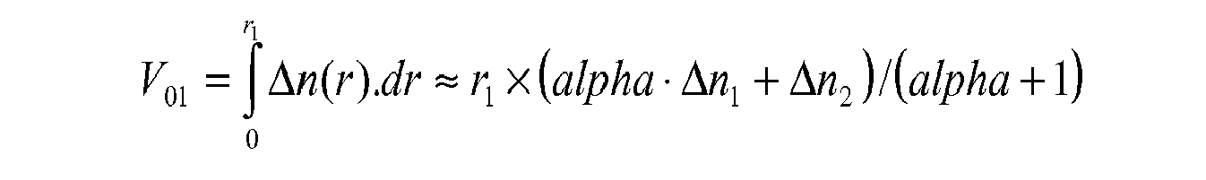
- In a first embodiment of the present invention said central core has a surface integral V01 of between about 22 x 10-3 micron and 25 x 10-3 micron, the surface integral V01 being defined according to the following equation:

- In another embodiment of the present invention said buried trench has a surface integral V03 of between about -45 x 10-3 micron and -25 x 10-3 micron, the surface integral V03 being defined according to the following equation:

- In yet another embodiment of the present invention said central core has a volume integral V11 of between about 87 x 10-3 µm2 and 103 x 10-3 µm2, the volume integral V11 being defined according to the following equation:

- In yet another embodiment of the present invention said buried trench has a volume integral V13 of between about -1020
x 10-3 µm2 and -500 x 10-3 µm2, the volume integral V13 being defined according to the following equation:
- In yet another embodiment of the present invention said central core has a radius r1 of between about 4.9 microns and 6.6 microns.
- In yet another embodiment of the present invention the ratio (r1/r2) of said central core's radius r1 to said intermediate cladding's radius r2 is between about 0.5 and 0.9.
- In yet another embodiment of the present invention the mean ((r2+r3)/2) of said intermediate cladding's radius r2 and said buried trench's radius r3 is between about 9.5 microns and 15.5 microns.
- In yet another embodiment of the present invention said central core's maximum refractive-index difference Δn1 is between about 5.3 x 10⁻³ and 7.0 x 10⁻³.
- In yet another embodiment of the present invention said intermediate cladding's refractive-index difference Δn2 is between about -1 x 10⁻³ and 1 x 10⁻³.
- In yet another embodiment of the present invention said buried trench's refractive-index difference Δn3 is between about -10 x 10-3 and -1.4
x 10-3. - In yet another embodiment of the present invention, for a bending radius of 15 millimeters at a wavelength of 1550 nanometers, the optical fiber has bending losses of between about 0.060 x 10⁻³ dB/turn and 1.48 x 10⁻³ dB/turn.
- In yet another embodiment of the present invention, for a bending radius of 10 millimeters at a wavelength of 1550 nanometers, the optical fiber has bending losses of between about 3 x 10⁻³ dB/turn and 36 x 10-3 dB/turn.
- In yet another embodiment of the present invention, for a bending radius of 7.5 millimeters at a wavelength of 1550 nanometers, the optical fiber has bending losses of between about 0.01 dB/turn and 0.14 dB/turn.
- In yet another embodiment of the present invention, for a bending radius of 5 millimeters at a wavelength of 1550 nanometers, the optical fiber has bending losses of between about 0.03 dB/turn and 0.41 dB/turn.
- In yet another embodiment of the present invention, for a bending radius of 15 millimeters at a wavelength of 1625 nanometers, the optical fiber has bending losses of between about 0.5 x 10⁻³ dB/turn and 8.9 x 10⁻³ dB/turn.
- In yet another embodiment of the present invention, for a bending radius of 10 millimeters at a wavelength of 1625 nanometers, the optical fiber has bending losses of between about 0.011 dB/turn and 0.112 dB/turn.
- In yet another embodiment of the present invention, for a bending radius of 7.5 millimeters at a wavelength of 1625 nanometers, the optical fiber has bending losses of between about 0.03 dB/turn and 0.32 dB/turn.
- In yet another embodiment of the present invention, for a bending radius of 5 millimeters at a wavelength of 1625 nanometers, the optical fiber has bending losses of between about 0.08 dB/turn and 1.13 dB/turn.
- In yet another embodiment of the present invention the optical fiber has a zero-chromatic-dispersion wavelength of between 1300 nanometers and 1324 nanometers. at the zero-chromatic-dispersion wavelength, the optical fiber has a chromatic dispersion slope of 0.092 ps/(nm2·km) or less.
- In an embodiment of the present invention, the the optical fiber complies with the ITU-T G.657.A2 recommendations.
- In another embodiment, the present invention relates to a single-mode optical fiber wherein the optical fiber complies with the ITU-T G.652.D recommendations; and the optical fiber has, at a wavelength of 1550 nanometers, (i) bending losses of no more than 0.03 dB/turn for a bending radius of 10 millimeters, (ii) bending losses of no more than 0.08 dB/turn for a bending radius of 7.5 millimeters, and (iii) bending losses of no more than 0.15 dB/turn for a bending radius of 5 millimeters; and the optical fiber has, at a wavelength of 1625 nanometers, (i) bending losses of no more than 0.01 dB/turn for a bending radius of 15 millimeters, (ii) bending losses of no more than 0.1 dB/turn for a bending radius of 10 millimeters, (iii) bending losses of no more than 0.25 dB/turn for a bending radius of 7.5 millimeters, and (iv) bending losses of no more than 0.45 dB/turn for a bending radius of 5 millimeters.
- In another embodiment, the present invention relates to a single-mode optical fiber comprising:
- a central core surrounded by an outer cladding, said central core having (i) a radius r1 of between 4.9 microns and 6.6 microns, (ii) a maximum refractive-index difference Δn1 with respect to said outer cladding of between 5.3 x 10⁻³ and 7.0 x 10⁻³, and (iii) an alpha refractive-index profile with an alpha parameter α of between 1.5 and 2.5;
- an intermediate cladding positioned between said central core and said outer cladding, said intermediate cladding having a radius r2 and a refractive-index difference Δn2 with respect to said outer cladding of between -1 x 10⁻³ and 1 x 10⁻³; and
- a buried trench positioned between said intermediate cladding and said outer cladding, said buried trench having a radius r3 and a negative refractive-index difference Δn3 with respect to said outer cladding of between -10 x 10-3 and -1.4
x 10-3. - In a preferred form of this embodiment, the ratio (r1/r2) of said central core's radius r1 to said intermediate cladding's radius r2 is between 0.5 and 0.9; and the mean ((r2+r3)/2) of said intermediate cladding's radius r2 and said buried trench's radius r3 is between 9.5 microns and 15.5 microns. In other preferred forms of this embodiment the optical fiber complies with the ITU-T G.657.A1 recommendations or the ITU-T G.657.A2 recommendations.
- In another embodiment, the present invention relates to a single-mode optical fiber comprising:
- a central core surrounded by an outer cladding, said central core having (i) a radius r1, (ii) a positive, maximum refractive-index difference Δn1 with respect to said outer cladding, (iii) an alpha refractive-index profile with an alpha parameter α of between 1.5 and 2.5, (iv) a surface integral V01 of between 22 x 10-3 micron and 25 x 10-3 micron, and (v) a volume integral V11 of between 87 x 10-3 µm2 and 103 x 10-3 µm2, the surface integral V01 and the volume integral V11 being defined according to the following equations:

- an intermediate cladding positioned between said central core and said outer cladding, said intermediate cladding having a radius r2 and a refractive-index difference Δn2 with respect to said outer cladding; and
- a buried trench positioned between said intermediate cladding and said outer cladding, said buried trench having (i) a radius r3, (ii) a negative refractive-index difference Δn3 with respect to said outer cladding, (iii) a surface integral V03 of between -45 x 10-3 micron and -25 x 10-3 micron, and (iv) a volume integral V13 of between -1020
x 10-3 µm2 and -500 x 10-3 µm2, the surface integral V03 and the volume integral V13 being defined according to the following equations:

- Moreover, the present invention relates to an optical box comprising at least a portion of the present optical fiber, preferably wherein the optical fiber is arranged with a radius of curvature of less than 15 millimeters, more preferably with a radius of curvature of about 5 millimeters.
- Moreover, the present invention relates to a fiber-to-the-home (FTTH) system comprising at least a portion of an optical fiber according to the invention.
- Accordingly, in one aspect, the present invention embraces an optical fiber that provides better resistance to bending losses than the limits set by the ITU-T G.657.A recommendations and the ITU-T G.657.B recommendations for a given mode field diameter (MFD), a given cable cut-off wavelength, and a given zero dispersion wavelength (ZDW), while remaining compatible with ITU-T G.652 recommendations.
- In this regard, the present invention embraces an optical-fiber profile that includes a central core, an intermediate cladding, and a buried trench. The core employs a parabolic profile (e.g., an alpha-index profile) instead of a step-index profile. It has been observed that the parabolic-index profile enables reduced bending losses (e.g., by as much as 30 percent) compared with a step-index profile, with the mode field diameter (MFD), cable cut-off wavelength, and zero-dispersion wavelength (ZDW) characteristics otherwise remaining substantially the same.
- A reduction in bending losses makes it possible to enlarge the acceptable window for MAC values by about 0.05, which represents a significant improvement compared with prior optical-fiber designs.
- The present invention also facilitates an increased tolerance to variability in the optical-fiber fabrication process.
- In a particular embodiment, the present invention embraces a single-mode optical fiber that includes, from its center towards its periphery, (i) a central core, (ii) an intermediate cladding, (iii) a buried trench, and (iv) an outer cladding.
- The central core has a radius r1 and a positive index difference Δn(r) relative to the outer cladding. The radius r1 of the central core is typically between about 4.9 microns and 6.6 microns. The maximum refractive-index difference Δn1 between the central core and the outer cladding is typically between 5.3 x 10⁻³ and 7.0 x 10⁻³. The central core typically possesses an alpha-index profile where the alpha parameter α is equal to 2 ± 0.5.
- The intermediate cladding has a radius r2 and an index difference Δn2 relative to the outer cladding. The refractive-index difference Δn2 between the intermediate cladding and the outer cladding is typically between -1 x 10⁻³ and 1 x 10⁻³. In one exemplary embodiment, the intermediate cladding's refractive index difference Δn2 is positive (e.g., at least about 0.1 x 10⁻³). In an alternative exemplary embodiment, the intermediate cladding's refractive index difference Δn2 is negative (e.g., no more than about -0.1 x 10⁻³).
- The buried trench has a radius r3 and a negative index difference Δn3 relative to the outer cladding. The refractive-index difference Δn3 between the buried trench and the outer cladding is typically between -10 x 10-3 and -1.4
x 10-3. - An optical fiber in accordance with the present invention typically has (i), at a wavelength of 1310 nanometers, a mode field diameter with a nominal value of between 8.6 microns and 9.5 microns and a tolerance of ±0.4 micron, (ii) a cable cut-off wavelength of no more than 1260 nanometers, and (iii), for a radius of curvature (i.e., bending radius) of 15 millimeters at a wavelength of 1550 nanometers, bending losses of no more than 0.003 dB/turn.
- The central core may have a surface integral V01 of between about 22 x 10-3 micron and 25 x 10-3 micron. The surface integral V01 of the central core is defined as follows:

- The central core may also have a volume integral V11 of between about 87 x 10-3 µm2 and 103 x 10-3 µm2. The surface volume V11 of the central core is defined as follows:

- The buried trench may have a surface integral V03 of between about -45 x 10-3 micron and -25 x 10-3 micron. The surface integral V03 of the buried trench is defined as follows:

- The buried trench may also have a volume integral V13 of between about -1020
x 10-3 µm2 and -500 x 10-3 µm2. The volume integral V11 of the buried trench is defined as follows:
- In one embodiment, the ratio of the central core's radius to the intermediate cladding's radius (i.e., r1/r2) is between 0.5 and 0.9.
- In yet another embodiment, the mean value of the intermediate cladding's radius and the buried trench's radius (i.e., (r2+r3)/2) is between 9.5 microns and 15.5 microns.
- In yet another embodiment, the optical fiber has, at a wavelength of 1550 nanometers, (i) bending losses of between about 0.060 x 10⁻³ dB/turn and 1.48 x 10⁻³ dB/turn for a radius of curvature of 15 millimeters, (ii) bending losses of between about 3 x 10⁻³ dB/turn and 36 x 10-3 dB/turn for a radius of curvature of 10 millimeters, (iii) bending losses of between about 0.01 dB/turn and 0.14 dB/turn for a radius of curvature of 7.5 millimeters, and/or (iv) bending losses of between about 0.03 dB/turn and 0.41 dB/turn for a radius of curvature of 5 millimeters.
- In yet another embodiment, the optical fiber has, at a wavelength of 1625 nanometers, (i) bending losses of between about 0.5 x 10⁻³ dB/turn and 8.9 x 10⁻³ dB/turn for a radius of curvature of 15 millimeters, (ii) bending losses of between about 0.011 dB/turn and 0.112 dB/turn for a radius of curvature of 10 millimeters, (iii) bending losses of between about 0.03 dB/turn and 0.32 dB/turn for a radius of curvature of 7.5 millimeters, and/or (iv) bending losses of between about 0.08 dB/turn and 1.13 dB/turn for a radius of curvature of 5 millimeters.
- In yet another embodiment, the optical fiber has a zero-chromatic-dispersion wavelength (ZDW) of between 1300 nanometers and 1324 nanometers.
- In yet another embodiment, the optical fiber has, at the zero-chromatic-dispersion wavelength, a chromatic-dispersion slope (ZDS) that is 0.092 ps/(nm2·km) or less.
- In another aspect, the present invention embraces an optical box receiving at least a portion of the present optical fiber. Within the optical box, the optical fiber may be arranged with a radius of curvature of less than 15 millimeters (e.g., a radius of curvature of less than 5 millimeters).
- In yet another aspect, the present invention embraces a fiber-to-the-home (FTTH) system that includes at least a portion of the present optical fiber.
- The foregoing illustrative summary, as well as other exemplary objectives and/or advantages of the invention, and the manner in which the same are accomplished, are further explained within the following detailed description and its accompanying drawing.
- Figure 1 depicts a refractive-index profile for an exemplary optical fiber according to the present invention. This refractive-index profile is a design profile, which is representative of the optical fiber's theoretical profile.
- In one aspect, the present invention embraces an optical fiber that includes (i) a central core, (ii) an intermediate cladding, (iii) a buried trench (e.g., a depressed cladding), and (iv) an outer cladding.
- The central core has a radius r1 and an index difference Δn(r) relative to the outer cladding, which acts as an optical cladding. The refractive index of the core typically has a parabolic shape. Accordingly, the refractive-index difference Δn(r) between the central core and the outer cladding depends on the distance r from the center of the optical fiber (e.g., decreasing as the distance from the center of the optical fiber increases). Thus, the central core defines a maximum refractive-index difference Δn1 with respect to the outer cladding. As used herein, the term "refractive-index difference" does not exclude a refractive-index difference of zero.
- The intermediate cladding has (i) a radius r2 and (ii) a refractive-index difference Δn2 with respect to the outer cladding that is typically constant. The buried trench has (i) a radius r3 and (ii) a refractive-index difference Δn3 with respect to the outer cladding that is typically constant. As used herein, the term "buried trench" is used to designate a radial portion of the optical fiber having a refractive index lower than the refractive index of the outer cladding.
- The central core's refractive-index difference Δn(r) with respect to the outer cladding may be described the following equation:

- At the center of the central core (i.e., where r = 0), the refractive-index difference Δn(r) is typically the central core's maximum refractive-index difference Δn1. At the edge of the central core (i.e., where r = r1), the refractive-index difference Δn(r) is typically equal to the intermediate cladding's refractive-index difference Δn2.
- The central core typically has an alpha-index profile. An alpha refractive-index profile may be described by an alpha parameter α(i.e., alpha), which is a non-dimensional parameter that is indicative of the shape of the index profile.
- An optical fiber with an alpha-index profile typically has a core profile with a rotational symmetry such that, along any radial direction of the optical fiber, the value of the refractive index decreases continuously from the center of the optical fiber's core to its periphery.
- A true parabolic shape is obtained when the alpha parameter α is equal to 2. That said, an alpha parameter α of between about 1.5 and 2.5 still facilitates desirable fiber characteristics. Accordingly, the alpha parameter α of the present optical fiber is typically between 1.5 and 2.5.
- Each section of the optical fiber profile may be defined using surface integrals and volume integrals. The term "surface" should not be understood geometrically but rather should be understood as a value having two dimensions. Similarly, the term "volume" should not be understood geometrically but rather should be understood as a value having three dimensions.
- Accordingly, the central core may define a surface integral V01, the intermediate cladding may define a surface integral V02, and the buried trench may define a surface integral V03. As used herein, these surface integrals are defined by the following equations, respectively:

- Moreover, the central core may define a volume integral V11, the intermediate cladding may define a volume integral V12, and the buried trench may define a volume integral V13. As used herein, these volume integrals are defined by the following equations, respectively:

- Table 3 (below) depicts three prophetic, exemplary parabolic-core fiber profiles in accordance with the present invention. Table 3 also depicts three prophetic, comparative step-index fiber profiles. The values in Table 3 correspond to the theoretical refractive-index profiles.
- The first column of Table 3 lists the exemplary and comparative optical fibers. The second column specifies whether the core has a step-index profile or a parabolic profile. The next three columns provide the core radius, the intermediate-cladding radius, and the buried trench radius. The last three columns depict index differences relative to the outer cladding. The refractive-index differences in Table 3 have been multiplied by 1000, as are the ordinate values in Figure 1. The refractive-index values were measured at a wavelength of 633 nanometers.
Table 3 core r1 (µm) r2 (µm) r3 (µm) Δn1 Δn2 Δn3 Comp. Ex. 1 step 3.93 9.38 14.72 5.33 0.13 -5.01 Ex 1parabola 5.76 9.38 14.72 6.21 -0.46 -5.01 Comp. Ex. 2 step 3.89 9.38 13.34 5.30 0.25 -7 00 Ex. 2 parabola 5.67 9.38 13.34 6.17 -0.27 -7.00 Comp. Ex. 3 step 3.91 9.23 14.81 5.14 0.10 -7 15 Ex 3parabola 5.73 9.23 14.81 5.98 -0.50 -7 15 - As depicted in Table 3, the central core typically has a radius r1 of between 5.67 microns and 5.76 microns and a maximum index difference Δn1 relative to the outer cladding of between 5.98 x 10⁻³ and 6.21 x 10⁻³. The intermediate cladding typically has a radius r2 of between 9.23 microns and 9.38 microns and an index difference Δn2 relative to the outer cladding of between -0.5 x 10⁻³ and -0.27
x 10-3. The buried trench typically has a radius r3 of between 13.34 microns and 14.81 microns and an index difference Δn3 relative to the outer cladding of between -7.15 x 10⁻³ and -5.01x 10⁻³. - Table 4 (below) shows optical transmission characteristics for optical fibers having the refractive-index profiles depicted in Table 3.
- The first and second columns identify the exemplary and comparative optical fibers, as well as their respective refractive-index profiles. The next columns provide, for each optical-fiber profile, the cable cut-off wavelength, the in-fiber cut-off wavelength, the zero chromatic dispersion wavelength (ZDW), the dispersion slope (ZDS) (in ps/(nm2.km)) at the zero chromatic dispersion wavelength, and the mode field diameters (MFD) at wavelengths of 1310 nanometers and 1550 nanometers, respectively.
Table 5 (below) shows bending losses (dB/turn) for optical fibers having the refractive-index profiles depicted in Table 3 for the wavelengths of 1550 nanometers and 1625 nanometers for radii of curvature of 15 millimeters, 10 millimeters, 7.5 millimeters, and 5 millimeters. Here, the bending-loss differences between the values for a step profile and the values for a parabolic profile are expressed as a percentage.Table 4 core cable cut-off wavelength (nm) in-fiber cut-off wavelength (nm) ZDW (nm) ZDS (ps/(nm3-km)) MFD (@ 1310 nm) (µm) MFD (@ 1550 nm) (µm) Comp Ex. 1 step 1202 1274 1319 0.087 6.76 9.84 Ex 1parabola 1202 1280 1319 0.090 8.78 9.84 difference Comp Ex 1 &Ex 1parabola vs. step 0 6 0 0.003 0.02 0.00 Comp Ex 2step 1189 1248 1319 0.088 8.80 9.88 Ex. 2 parabola 1169 1255 1319 0.091 8.82 9.88 difference Comp Ex. 2 & Ex 2parabola vs. step 0 7 0 0.003 0.02 0.00 Comp. Ex. 3 step 1227 1364 1317 0.089 8.80 9.86 Ex. 3 parabola 1227 1377 1317 0.091 8.82 9.86 difference Comp Ex. 3 & Ex. 3 parabola vs step 0 13 0 0.002 0.02 0.00 Table 5 Bending losses (@ 1550 nm) (dB/turn) Bending losses (@ 1625nm) (dB/turn) 15-mm bend radius 10-mm bend radius 75-mm bend radius 5-mm bend radius 15-mm bend radius 10-mm bend radius 75-mm bend radius 5-mm bend radius Comp Ex 1 0.00088 0.024 0.091 0.22 0.0052 0.071 0.204 0.49 Ex 10.00063 0.018 0.071 0.17 0.0038 0.056 0.162 0.39 Difference between Comp. Ex 1 & Ex 1-29% -25% -22% -23% -27% -21% -21% -20% Comp. Ex 20.00128 0.034 0.134 0.30 0.0073 0.101 0.293 0.67 Ex 20.00090 0.026 0.105 0.25 0.0052 0.079 0.235 0.55 Difference between Comp. Ex 2 &Ex2-30% -24% -22% -17% -29% -22% -20% -18% Comp. Ex 30.00082 0.012 0.037 0.07 0.0044 0.035 0.082 0.16 Ex 30.00067 0.010 0.031 0.06 0.0036 0.029 0.069 0.14 Difference between Comp. Ex 3 & Ex 3-18% -17% -16% -14% -18% -17% -16% -13% - In accordance with Tables 4 and 5 (above), the present optical fibers can have bending losses that are as much as 30 percent less than the comparative optical fibers, which have a step-index profile. Moreover, the present optical fibers typically have substantially the same (i) cable cut-off wavelength, (ii) zero-chromatic-dispersion wavelength (ZDW), (iii) zero-dispersion slope (ZDS), and (iv) mode field diameter (MFD) as the comparative optical fibers.
- Moreover, the optical fiber in accordance with the present invention typically has optical transmission parameters in compliance with the ITU-T G.652 and G.657 recommendations.
- Indeed, as shown in Table 4 (above) and in accordance with the ITU-T G.652 recommendations, the present optical fibers typically have (i) a nominal mode field diameter of between 8.6 microns and 9.5 microns at a wavelength of 1310 nanometers, (ii) a zero-chromatic-dispersion wavelength of between 1300 nanometers and 1324 nanometers, and (iii) a maximum chromatic-dispersion slope of no more than 0.092 ps/(nm2·km) at the zero-dispersion wavelength. Furthermore, the present optical fiber typically has a cable cut-off wavelength that is well below 1260 nanometers, the maximum value allowed by the ITU-T G.652 and G.657 recommendations.
- It is desirable to produce optical fibers that are suitable for use over all of the transmission bands used by optical systems. In particular, it is desirable to use optical fiber in single-mode propagation from the original band (O-band) (i.e., 1260 nanometers to 1360 nanometers) up to the ultra-long band (U-band) (i.e., greater than 1625 nanometers). A low cut-off wavelength facilitates use of the optical fiber in all available bands.
- By comparing Table 5 with Table 1, it can be seen that the bending losses of the present optical fibers (e.g., Examples 1, 2, and 3) typically comply with the limits set by the ITU-T G.652.D and G.657.A1/A2/B2 recommendations. Moreover, the bending losses of Example 3 even comply with the more rigorous limits set by the ITU-T G.657.B3 recommendations.
- Thus, with reference to Example 3, the present optical fiber can have, at a wavelength of 1550 nanometers, (i) bending losses of no more than 0.003 dB/turn (e.g., 0.00067 dB/turn) for a bending radius of 15 millimeters, (ii) bending losses of no more than 0.03 dB/turn (e.g., 0.01 dB/turn) for a bending radius of 10 millimeters, (iii) bending losses of no more than 0.08 dB/turn (e.g., 0.031 dB/turn) for a bending radius of 7.5 millimeters, and (iv) bending losses of no more than 0.15 dB/turn (e.g., 0.06 dB/turn) for a bending radius of 5 millimeters.
- With further reference to Example 3, the present optical fiber can also have, at a wavelength of 1625 nanometers, (i) bending losses of no more than 0.01 dB/turn (e.g., 0.0036 dB/turn) for a bending radius of 15 millimeters, (ii) bending losses of no more than 0.1 dB/turn (e.g., 0.029 dB/turn) for a bending radius of 10 millimeters, (iii) bending losses of no more than 0.25 dB/turn (e.g., 0.069 dB/turn) for a bending radius of 7.5 millimeters, and (iv) bending losses of no more than 0.45 dB/turn (e.g., 0.14 dB/turn) for a bending radius of 5 millimeters.
- Table 6 (below) depicts twelve exemplary parabolic-core fiber profiles in accordance with the present invention. Note that Examples 1-3 in Table 6 are the same as in Table 3. The values in Table 6 correspond to the theoretical refractive-index profiles.
- The first column of Table 6 lists the prophetic, exemplary optical fibers. The second column provides the value of the alpha parameter. The next three columns provide the radii of the core, the intermediate cladding, and the buried trench. The next three columns provide the corresponding index differences relative to the optical cladding. The next two columns provide values for (r2+r3)/2 and for the ratio r1/r2, respectively. Finally, the last six columns provide respective values for the surface and volume integrals V01, V11, V02, V12, V03, and V13. As before, the refractive-index differences and the integrals in Table 6 have been multiplied by 1000. The refractive-index values were measured at a wavelength of 633 nanometers.
Table 6 alpha r1 (µm) r2 (µm) r3 (µm) Δn1 Δn2 Δn3 (r2+r3)/2(µm) r1/r2 V01 (µm) V11(µm2) V02 (µm) V12 (µm2) V03 (µm) V13 (µm2) Ex 12.00 5.76 9.38 14.72 6.21 -0.46 -5.01 12.05 0.61 23 95 -1.7 -25.2 -27 -645 Ex. 2 2.00 5.67 9.38 13.34 6.17 -0.27 -7.00 11.36 0.60 23 95 -1.0 -15.1 -28 -630 Ex. 3 2.00 5.73 9.23 14.81 5.98 -0.50 -7.15 12.02 0.62 22 90 -1.8 -26.2 -40 -959 Ex 42.47 5.95 9.05 15.17 5.34 -0.29 -5.21 12.11 0.66 22 100 -0. 9 -13.5 -32 -772 Ex 51.73 6. 12 8.16 12.96 6.35 -0.83 -5.45 10.56 0.75 23 94 -1.7 -24.2 -26 -552 Ex 61.69 6. 56 9.34 18. 40 6.17 -0. 94 -2.93 13.87 0.70 23 100 -2.6 -41.5 -27 -736 Ex 71.55 5. 21 6.16 16.49 6.53 0.90 -2.78 11.33 0.85 23 91 0.9 9.7 -29 -650 Ex.8 1.84 5.28 6.83 23.65 6.30 0.44 -1.48 15.34 0.77 22 91 0.7 8.3 -25 -773 Ex. 9 1.72 5.98 8.82 15.82 6.75 -0.53 -4.30 12.32 0.68 24 101 -1.5 -22.3 -30 -742 Ex. 10 1.77 6.08 9.21 14.46 6.49 -0.72 -8.10 11.84 0.66 24 99 -2.3 -34.5 -43 -1007 Ex 112.3 5.12 7.53 14. 93 6.42 0.42 -5.32 11.23 0.68 24 95 1.0 12.8 -39 -884 Ex 121.7 6.06 11.04 15 .00 6.31 -0.35 -9.05 13.02 0.55 23 100 -1.7 -29.8 -36 -933 - In accordance with the foregoing, the present optical fibers typically have the following properties: (i) a central core radius r1 of between 4.9 microns and 6.6 microns; (ii) a ratio (i.e., r1/r2) of the central core's radius to the intermediate cladding's radius of between 0.5 and 0.9; (iii) a mean value (i.e., (r2+r3)/2) of the intermediate cladding's radius and the buried trench's radius of between 9.5 microns and 15.5 microns; (iv) a maximum central-core refractive-index difference Δn1 of between 5.3 x 10⁻³ and 7.0 x 10⁻³; (v) an intermediate-cladding refractive-index difference Δn2 of between -1 x 10⁻³ and 1 x 10⁻³; (vi) a buried-trench refractive-index difference Δn3 of between -10 x 10-3 and -1.4 x 10⁻³; (vii) a central-core surface integral V01 of between 22 x 10-3 micron and 25 x 10-3 micron; (viii) a central-core volume integral V11 of between 87 x 10-3 µm2 and 103 x 10-3 µm2; (ix) a buried-trench surface integral V03 of between -45 x 10-3 micron and -25 x 10-3 micron; and (x) a buried-trench volume integral V13 of between -1020 x 10-3 µm2 and -500 x 10-3 µm2.
- These optical-fiber properties are provided as exemplary ranges in Table 7 (below):
Table 7 r1 r1/r2 (r2+r3)/2 Δn1 Δn2 Δn3 V01 V11 V03 V13 [4.9,6.6] [0.5,0.9] [9.5.15.5] [5.3,7.0] [-1,+1] [-10,1.5] [22,25] [87,103] [-45,-25] [-1020,-500] - Table 8 (below) shows optical transmission characteristics for optical fibers having the refractive-index profiles depicted in Table 6.
Table 8 cable cut-off
wavelength (nm)in-fiber cut-off
wavelength (nm)ZDW
(nm)ZDS
(ps/(nm2-km))MFC
(@ 1310 nm) (µm)MFD
(@ 1550 nm) (µm)Ex. 1 1202 1280 1319 0.090 8.78 9.84 Ex. 2 1189 1255 1319 0.091 8.82 9.88 Ex. 3 1227 1377 1317 0.091 8.82 9.86 Ex. 4 1244 1251 1307 0.092 9.32 10.3 Ex. 5 1161 1347 1312 0.092 8.68 9.63 Ex. 6 1260 1222 1316 0.091 9.01 10.1 Ex. 7 1179 1374 1312 0.092 8.6 9.56 Ex. 8 1257 1270 1324 0.089 8.81 9.95 Ex. 9 1251 1353 1320 0.091 8.64 9.66 Ex.10 1260 1351 1316 0.092 8.7 9.69 Ex.11 1259 1414 1313 0.092 8.6 9.54 Ex.12 1250 1318 1324 0.089 8.98 10.1 - Table 9 (below) shows bending losses for optical fibers having the refractive-index profiles depicted in Table 6.
Table 9 bending losses (@ 1550 nm) (dB/turn) bending losses (@ 1625 nm) (dB/turn) 15-mm bend radius 10-mm bend radius 7.5-mm bend radius 5-mm bend radius 15-mm bend radius 10-mm bend radius 75-mm bend radius 5-mm bend radius Ex.1 0. 00063 0.018 0.07 0.17 0.0038 0.056 0.16 0.39 Ex. 2 0. 00090 0.026 0.11 0.25 0.0052 0.079 0.23 0.55 Ex. 3 0. 00067 0.010 0.03 0.06 0.0036 0.029 0.07 0.14 Ex 40. 00112 0.020 0.06 0.14 0.0055 0.054 0.14 0.31 Ex. 5 0. 00148 0.036 0.14 0.31 0.0089 0.112 0.32 0.7 Ex 60 .00043 0.009 0.03 0.09 0.0023 0.027 0.07 0.23 Ex. 7 0. 00143 0.024 0.08 0.19 0.0082 0.072 0.18 0.45 Ex 80. 00054 0.008 0.04 0.41 0.0027 0.026 0.10 1.13 Ex. 9 0 .00009 0.005 0.02 0.07 0.0007 0.016 0.06 0.16 Ex. 10 0. 00009 0.003 0.01 0.03 0.0006 0.011 0.03 0.08 Ex. 11 0. 00006 0.003 0.01 0.04 0.0005 0.011 0.04 0.1 Ex. 12 0. 00028 0.008 0 03 0.08 0.0016 0.024 0.07 0.17 - An optical fiber in accordance with the present invention may be obtained by drawing a preform. The preform may be constituted from a tube of high-quality glass (pure silica) that forms a portion of the outer cladding. This tube may then be overclad to increase its diameter prior to fiber drawing within a fiber-drawing tower. In order to fabricate the preform, the tube is generally mounted horizontally and held at both ends by glass bars in a glass-making lathe. Thereafter, the tube is rotated and heated locally for depositing components that determine the composition of the preform. Those of ordinary skill in the art will appreciate that the composition of the preform determines the optical characteristics of the final fiber.
- In this regard, the central core, the intermediate cladding, and the buried trench are typically obtained by chemical vapor deposition (CVD) in a tube of silica. The outer cladding is typically formed from the silica tube and the overcladding of the silica tube. The outer cladding may be made of undoped (e.g., natural) or doped silica.
- The foregoing notwithstanding, other techniques may be used to form the preform. For example, vapor axial deposition (VAD), outside vapor deposition (OVD), and/or plasma chemical vapor deposition (PCVD) may be employed.
- By way of further example, the buried trench may be formed using plasma chemical vapor deposition (PCVD), thereby enabling a large quantity of fluorine to be incorporated into the silica; doping the silica with fluorine facilitates the formation of a deeply buried trench. Alternatively, the buried trench may be formed by incorporating microholes or microbubbles into the silica.
- Optical fibers in accordance with the present invention are well suited for use in various optical communication systems. Because the present optical fibers typically have low bending losses, the present optical fibers are particularly suited for installations (e.g., fiber-to-the-home (FTTH) systems) where the optical fiber is subjected to significant bending stresses (e.g., due to the miniaturization of optical boxes or fastening by means of staples). Accordingly, the present optical fibers can placed in optical boxes that are particularly compact. For example, within an optical box, the optical fiber may be arranged with a radius of curvature (i.e., bending radius) of less than 15 millimeters (e.g., a radius of curvature of less than 5 millimeters).
- The present optical fibers are suitable for many optical communication systems, because the present optical fibers are typically compatible with conventional optical fibers. For example, the present optical fibers are typically compatible with conventional optical fibers with respect to mode field diameter, thereby facilitating good fiber-to-fiber coupling.
- In the specification and/or figure, typical embodiments of the invention have been disclosed. The present invention is not limited to such exemplary embodiments. The use of the term "and/or" includes any and all combinations of one or more of the associated listed items. The figure is a schematic representation and so is not necessarily drawn to scale. Unless otherwise noted, specific terms have been used in a generic and descriptive sense and not for purposes of limitation.
Claims (15)
- A single-mode optical fiber, comprising:a central core surrounded by an outer cladding, said central core having (i) a radius r1, (ii) a positive, maximum refractive-index difference Δn1 with respect to said outer cladding, and (iii) an alpha refractive-index profile with an alpha parameter α of between 1.5 and 2.5;an intermediate cladding positioned between said central core and said outer cladding, said intermediate cladding having a radius r2 and a refractive-index difference Δn2 with respect to said outer cladding; anda buried trench positioned between said intermediate cladding and said outer cladding, said buried trench having a radius r3 and a negative refractive-index difference Δn3 with respect to said outer cladding;wherein the optical fiber has (i), at a wavelength of 1310 nanometers, a mode field diameter with a nominal value of between 8.6 microns and 9.5 microns and a tolerance of ±0.4 micron, (ii) a cable cut-off wavelength of 1260 nanometers or less, and (iii), for a bending radius of 15 millimeters at a wavelength of 1550 nanometers, bending losses of 0.003 dB/turn or less.
- A single-mode optical fiber according to claim 1, wherein said central core has a surface integral V01 of between about 22 x 10-3 micron and 25 x 10-3 micron, the surface integral V01 being defined according to the following equation:

- A single-mode optical fiber according to any one of the preceding claims, wherein said buried trench has a surface integral V03 of between about -45 x 10-3 micron and -25 x 10-3 micron, the surface integral V03 being defined according to the following equation:

- A single-mode optical fiber according to any one of the preceding claims, wherein said central core has a volume integral V11 of between about 87 x 10-3 µm2 and 103 x 10-3 µm2, the volume integral V11 being defined according to the following equation:

- A single-mode optical fiber according to any one of the preceding claims, wherein said buried trench has a volume integral V13 of between about -1020 x 10-3 µm2 and -500 x 10-3 µm2, the volume integral V13 being defined according to the following equation:

- A single-mode optical fiber according to any one of the preceding claims, wherein said central core has a radius r1 of between about 4.9 microns and 6.6 microns and/or wherein said central core's maximum refractive-index difference Δn1 is between about 5.3 x 10⁻³ and 7.0 x 10⁻³.
- A single-mode optical fiber according to any one of the preceding claims, wherein the ratio (r1/r2) of said central core's radius r1 to said intermediate cladding's radius r2 is between about 0.5 and 0.9 and/or wherein said intermediate cladding's refractive-index difference Δn2 is between about -1 x 10⁻³ and 1 x 10⁻³.
- A single-mode optical fiber according to any one of the preceding claims, wherein the mean ((r2+r3)/2) of said intermediate cladding's radius r2 and said buried trench's radius r3 is between about 9.5 microns and 15.5 microns and/or wherein said buried trench's refractive-index difference Δn3 is between about -10 x 10-3 and -1.4 x 10⁻³.
- A single-mode optical fiber according to any one of the preceding claims, wherein, for a bending radius of 15 millimeters at a wavelength of 1550 nanometers, the optical fiber has bending losses of between about 0.060 x 10⁻³ dB/turn and 1.48 x 10⁻³ dB/turn.
- A single-mode optical fiber according to any one of the preceding claims, wherein, for a bending radius of 10 millimeters at a wavelength of 1550 nanometers, the optical fiber has bending losses of between about 3 x 10⁻³ dB/turn and 36 x 10-3 dB/turn.
- A single-mode optical fiber according to any one of the preceding claims, wherein, for a bending radius of 7.5 millimeters at a wavelength of 1550 nanometers, the optical fiber has bending losses of between about 0.01 dB/turn and 0.14 dB/turn.
- A single-mode optical fiber according to any one of the preceding claims, wherein, for a bending radius of 5 millimeters at a wavelength of 1550 nanometers, the optical fiber has bending losses of between about 0.03 dB/turn and 0.41 dB/turn.
- A single-mode optical fiber according to any one of the preceding claims, wherein the optical fiber has a zero-chromatic-dispersion wavelength of between 1300 nanometers and 1324 nanometers and/or a chromatic dispersion slope of 0.092 ps/(nm2·km) or less.
- An optical box comprising at least a portion of an optical fiber according to to any one of the preceding claims, preferably wherein the optical fiber is arranged with a radius of curvature of less than 15 millimeters, more preferably with a radius of curvature of about 5 millimeters.
- A fiber-to-the-home (FTTH) system comprising at least a portion of an optical fiber according to any one of the claims 1-13.
Applications Claiming Priority (1)
| Application Number | Priority Date | Filing Date | Title |
|---|---|---|---|
| FR1051879 | 2010-03-17 |
Publications (2)
| Publication Number | Publication Date |
|---|---|
| EP2369379A1 true EP2369379A1 (en) | 2011-09-28 |
| EP2369379B1 EP2369379B1 (en) | 2015-05-06 |
Family
ID=42988177
Family Applications (1)
| Application Number | Title | Priority Date | Filing Date |
|---|---|---|---|
| EP20110157416 Active EP2369379B1 (en) | 2010-03-17 | 2011-03-09 | Fibre optique monomode ayant des pertes par courbures réduites |
Country Status (5)
| Country | Link |
|---|---|
| US (1) | US8428411B2 (en) |
| EP (1) | EP2369379B1 (en) |
| CN (1) | CN102193141B (en) |
| DK (1) | DK2369379T3 (en) |
| ES (1) | ES2539824T3 (en) |
Cited By (4)
| Publication number | Priority date | Publication date | Assignee | Title |
|---|---|---|---|---|
| US8428411B2 (en) | 2010-03-17 | 2013-04-23 | Draka Comteq, B.V. | Single-mode optical fiber |
| WO2015092464A1 (en) | 2013-12-20 | 2015-06-25 | Draka Comteq Bv | Single mode fibre with a trapezoid core, showing reduced losses |
| US10962708B2 (en) | 2017-12-21 | 2021-03-30 | Draka Comteq France | Bending-loss insensitive single mode fibre, with a shallow trench, and corresponding optical system |
| EP3865920A1 (en) * | 2020-02-12 | 2021-08-18 | Sterlite Technologies Limited | Optical fibre having centerline core profile |
Families Citing this family (55)
| Publication number | Priority date | Publication date | Assignee | Title |
|---|---|---|---|---|
| ES2543879T3 (en) * | 2008-11-07 | 2015-08-25 | Draka Comteq B.V. | Fiber optic of reduced diameter |
| WO2010077132A1 (en) | 2008-12-31 | 2010-07-08 | Draka Comteq B.V. | Uvled apparatus for curing glass-fiber coatings |
| FR2946436B1 (en) | 2009-06-05 | 2011-12-09 | Draka Comteq France | MULTIMODE OPTICAL FIBER WITH LARGE BANDWIDTH WITH AN OPTIMIZED HEAT-SLEEVE INTERFACE |
| US9014525B2 (en) | 2009-09-09 | 2015-04-21 | Draka Comteq, B.V. | Trench-assisted multimode optical fiber |
| FR2949870B1 (en) * | 2009-09-09 | 2011-12-16 | Draka Compteq France | MULTIMODE OPTICAL FIBER HAVING IMPROVED BENDING LOSSES |
| US8693830B2 (en) | 2010-04-28 | 2014-04-08 | Draka Comteq, B.V. | Data-center cable |
| ES2587432T3 (en) | 2010-05-03 | 2016-10-24 | Draka Comteq B.V | Beam fiber optic cables |
| DK2388239T3 (en) | 2010-05-20 | 2017-04-24 | Draka Comteq Bv | Curing apparatus using angled UV LEDs |
| US8871311B2 (en) | 2010-06-03 | 2014-10-28 | Draka Comteq, B.V. | Curing method employing UV sources that emit differing ranges of UV radiation |
| FR2962230B1 (en) | 2010-07-02 | 2012-07-27 | Draka Comteq France | OPTICAL FIBER MONOMODE |
| US8682123B2 (en) | 2010-07-15 | 2014-03-25 | Draka Comteq, B.V. | Adhesively coupled optical fibers and enclosing tape |
| EP2418183B1 (en) | 2010-08-10 | 2018-07-25 | Draka Comteq B.V. | Method for curing coated glass fibres providing increased UVLED intensitiy |
| US8571369B2 (en) | 2010-09-03 | 2013-10-29 | Draka Comteq B.V. | Optical-fiber module having improved accessibility |
| FR2966256B1 (en) | 2010-10-18 | 2012-11-16 | Draka Comteq France | MULTIMODE OPTICAL FIBER INSENSITIVE TO LOSSES BY |
| US8824845B1 (en) | 2010-12-03 | 2014-09-02 | Draka Comteq, B.V. | Buffer tubes having reduced stress whitening |
| DK2482106T5 (en) | 2011-01-31 | 2014-09-22 | Draka Comteq Bv | Multi-mode fiber |
| FR2971061B1 (en) | 2011-01-31 | 2013-02-08 | Draka Comteq France | BROAD BANDWIDTH OPTICAL FIBER WITH LOW CURB LOSSES |
| BR112013021130A2 (en) | 2011-02-21 | 2019-08-27 | Draka Comteq Bv | fiber optic interconnect cable |
| EP2495589A1 (en) | 2011-03-04 | 2012-09-05 | Draka Comteq B.V. | Rare earth doped amplifying optical fiber for compact devices and method of manufacturing thereof |
| EP2503368A1 (en) | 2011-03-24 | 2012-09-26 | Draka Comteq B.V. | Multimode optical fiber with improved bend resistance |
| EP2506044A1 (en) | 2011-03-29 | 2012-10-03 | Draka Comteq B.V. | Multimode optical fiber |
| EP2518546B1 (en) | 2011-04-27 | 2018-06-20 | Draka Comteq B.V. | High-bandwidth, radiation-resistant multimode optical fiber |
| EP2527893B1 (en) | 2011-05-27 | 2013-09-04 | Draka Comteq BV | Single mode optical fiber |
| ES2451369T3 (en) | 2011-06-09 | 2014-03-26 | Draka Comteq Bv | Single mode fiber optic |
| DK2541292T3 (en) | 2011-07-01 | 2014-12-01 | Draka Comteq Bv | A multimode optical fiber |
| US8891925B2 (en) * | 2011-08-19 | 2014-11-18 | Corning Incorporated | Low bend loss optical fiber |
| EP2584340A1 (en) | 2011-10-20 | 2013-04-24 | Draka Comteq BV | Hydrogen sensing fiber and hydrogen sensor |
| NL2007831C2 (en) | 2011-11-21 | 2013-05-23 | Draka Comteq Bv | Apparatus and method for carrying out a pcvd deposition process. |
| US8929701B2 (en) | 2012-02-15 | 2015-01-06 | Draka Comteq, B.V. | Loose-tube optical-fiber cable |
| WO2013160714A1 (en) | 2012-04-27 | 2013-10-31 | Draka Comteq Bv | Hybrid single and multimode optical fiber for a home network |
| US9188754B1 (en) | 2013-03-15 | 2015-11-17 | Draka Comteq, B.V. | Method for manufacturing an optical-fiber buffer tube |
| US9057817B2 (en) * | 2013-04-15 | 2015-06-16 | Corning Incorporated | Low diameter optical fiber |
| NL2011075C2 (en) | 2013-07-01 | 2015-01-05 | Draka Comteq Bv | Pcvd process with removal of substrate tube. |
| WO2016017743A1 (en) | 2014-08-01 | 2016-02-04 | 株式会社フジクラ | Optical fiber and method for producing same |
| WO2016047675A1 (en) | 2014-09-26 | 2016-03-31 | 株式会社フジクラ | Optical fiber and method for manufacturing same |
| CN107111055B (en) | 2014-09-26 | 2020-02-21 | 株式会社藤仓 | Optical fiber |
| WO2017120730A1 (en) * | 2016-01-11 | 2017-07-20 | 周瑾 | Novel method of measuring mode field diameter of single-mode fiber using optical integration technique employing gradually-changing-aperture |
| US11067744B2 (en) * | 2017-11-30 | 2021-07-20 | Corning Incorporated | Low bend loss optical fiber with step index core |
| US10775558B2 (en) | 2018-02-05 | 2020-09-15 | Corning Incorporated | Low loss wide bandwidth optical fiber |
| JP7214352B2 (en) * | 2018-03-08 | 2023-01-30 | 古河電気工業株式会社 | optical fiber |
| US11181687B2 (en) | 2018-04-30 | 2021-11-23 | Corning Incorporated | Small diameter low attenuation optical fiber |
| JP2021523397A (en) * | 2018-04-30 | 2021-09-02 | コーニング インコーポレイテッド | Small outer diameter low attenuation optical fiber |
| US11181686B2 (en) | 2018-04-30 | 2021-11-23 | Corning Incorporated | Small diameter low attenuation optical fiber |
| EP3857275A4 (en) * | 2018-09-28 | 2022-10-12 | Corning Research & Development Corporation | Small diameter fiber optic cables having low-friction cable jackets and optical fibers with reduced cladding and coating diameters |
| CN109445034B (en) * | 2019-01-03 | 2020-07-14 | 荆门博谦信息科技有限公司 | Few-mode wavelength division multiplexing coupler |
| US11036000B2 (en) | 2019-01-16 | 2021-06-15 | Corning Incorporated | Optical fiber cable with high fiber count |
| US11714227B2 (en) * | 2019-06-17 | 2023-08-01 | Sterlite Technologies Limited | Universal optical fiber |
| WO2021025858A1 (en) | 2019-08-07 | 2021-02-11 | Corning Incorporated | Single mode optical fiber with low bend loss at small and large bend diameters |
| CN110488411B (en) * | 2019-08-19 | 2021-03-23 | 长飞光纤光缆股份有限公司 | Bending-resistant single-mode optical fiber |
| US11194107B2 (en) * | 2019-08-20 | 2021-12-07 | Corning Incorporated | High-density FAUs and optical interconnection devices employing small diameter low attenuation optical fiber |
| US11860406B2 (en) | 2019-11-08 | 2024-01-02 | Fujikura Ltd. | Optical fiber |
| JP7135207B2 (en) * | 2019-11-08 | 2022-09-12 | 株式会社フジクラ | optical fiber |
| JP2023519073A (en) | 2020-01-07 | 2023-05-10 | コーニング インコーポレイテッド | Reduced radius optical fiber with high mechanical reliability |
| WO2021231083A1 (en) | 2020-05-12 | 2021-11-18 | Corning Incorporated | Reduced diameter single mode optical fibers with high mechanical reliability |
| WO2022181614A1 (en) * | 2021-02-25 | 2022-09-01 | 住友電気工業株式会社 | Optical fiber |
Citations (11)
| Publication number | Priority date | Publication date | Assignee | Title |
|---|---|---|---|---|
| US20050244120A1 (en) * | 2004-04-29 | 2005-11-03 | Mishra Snigdharaj K | Low attenuation large effective area optical fiber |
| WO2005106544A1 (en) * | 2004-04-28 | 2005-11-10 | Ls Cable Ltd. | Optical fiber with improved bending behavior |
| EP1698920A1 (en) * | 2005-03-01 | 2006-09-06 | The Furukawa Electric Co., Ltd. | Optical fiber and optical interconnection system |
| EP1785754A1 (en) | 2005-11-10 | 2007-05-16 | Draka Comteq B.V. | Single mode optical fiber with low bending losses |
| EP1845399A1 (en) | 2006-04-10 | 2007-10-17 | Draka Comteq B.V. | Single-mode optical fibre with low bending losses still complying with the ITU-T G.652 specification |
| US20080056658A1 (en) * | 2006-08-31 | 2008-03-06 | Scott Robertson Bickham | Low bend loss optical fiber with deep depressed ring |
| EP1930753A1 (en) | 2006-12-04 | 2008-06-11 | Draka Comteq B.V. | Optical fiber with high Brillouin threshold power and low bending losses |
| US20080226241A1 (en) * | 2006-08-31 | 2008-09-18 | The Furukawa Electric Co., Ltd. | Optical fiber and optical fiber ribbon, and optical interconnection system |
| US20090169163A1 (en) * | 2007-12-13 | 2009-07-02 | Abbott Iii John Steele | Bend Resistant Multimode Optical Fiber |
| EP2116878A1 (en) | 2008-05-06 | 2009-11-11 | Draka Comteq B.V. | Bend-insensitive single-mode optical fiber |
| US20100027951A1 (en) * | 2008-07-30 | 2010-02-04 | Dana Craig Bookbinder | Low bend loss single mode optical fiber |
Family Cites Families (102)
| Publication number | Priority date | Publication date | Assignee | Title |
|---|---|---|---|---|
| US4838643A (en) | 1988-03-23 | 1989-06-13 | Alcatel Na, Inc. | Single mode bend insensitive fiber for use in fiber optic guidance applications |
| FR2647778B1 (en) | 1989-06-05 | 1992-11-20 | Comp Generale Electricite | METHOD AND DEVICE FOR EXTERNAL DEPOSITION BY HYDROXYLIC ION-FREE SILICA PLASMA |
| FR2713621B1 (en) | 1993-12-14 | 1996-01-05 | Alcatel Fibres Optiques | Method for plasma recharging of a preform for optical fiber and optical fiber originating from the preform recharged according to this method. |
| US5559921A (en) * | 1994-06-24 | 1996-09-24 | Sumitomo Electric Industries, Ltd. | Single mode optical fiber |
| US5574816A (en) | 1995-01-24 | 1996-11-12 | Alcatel Na Cable Sytems, Inc. | Polypropylene-polyethylene copolymer buffer tubes for optical fiber cables and method for making the same |
| US5717805A (en) | 1996-06-12 | 1998-02-10 | Alcatel Na Cable Systems, Inc. | Stress concentrations in an optical fiber ribbon to facilitate separation of ribbon matrix material |
| US7322122B2 (en) | 1997-01-15 | 2008-01-29 | Draka Comteq B.V. | Method and apparatus for curing a fiber having at least two fiber coating curing stages |
| FR2762836B1 (en) | 1997-05-02 | 1999-07-23 | Alsthom Cge Alcatel | PROCESS AND APPARATUS FOR MANUFACTURING FIBERGLASS PREFORMS |
| FR2760540B1 (en) | 1997-03-10 | 1999-04-16 | Alsthom Cge Alcatel | OPTICAL FIBER CABLE TIGHTENED IN SHEATH |
| US5911023A (en) | 1997-07-10 | 1999-06-08 | Alcatel Alsthom Compagnie Generale D'electricite | Polyolefin materials suitable for optical fiber cable components |
| US6269663B1 (en) | 1998-03-05 | 2001-08-07 | Alcatel | Method of purifying silica and depositing on an optical fiber preform |
| US6066397A (en) | 1998-03-31 | 2000-05-23 | Alcatel | Polypropylene filler rods for optical fiber communications cables |
| US6175677B1 (en) | 1998-04-17 | 2001-01-16 | Alcatel | Optical fiber multi-ribbon and method for making the same |
| US6085009A (en) | 1998-05-12 | 2000-07-04 | Alcatel | Water blocking gels compatible with polyolefin optical fiber cable buffer tubes and cables made therewith |
| JP4192425B2 (en) * | 1998-12-17 | 2008-12-10 | 住友電気工業株式会社 | Optical fiber |
| US6215931B1 (en) | 1999-01-26 | 2001-04-10 | Alcatel | Flexible thermoplastic polyolefin elastomers for buffering transmission elements in a telecommunications cable |
| US6134363A (en) | 1999-02-18 | 2000-10-17 | Alcatel | Method for accessing optical fibers in the midspan region of an optical fiber cable |
| US6381390B1 (en) | 1999-04-06 | 2002-04-30 | Alcatel | Color-coded optical fiber ribbon and die for making the same |
| US6181857B1 (en) | 1999-05-12 | 2001-01-30 | Alcatel | Method for accessing optical fibers contained in a sheath |
| US6314224B1 (en) | 1999-06-18 | 2001-11-06 | Alcatel | Thick-walled cable jacket with non-circular cavity cross section |
| US6334016B1 (en) | 1999-06-30 | 2001-12-25 | Alcatel | Optical fiber ribbon matrix material having optimal handling characteristics |
| US6321012B1 (en) | 1999-08-30 | 2001-11-20 | Alcatel | Optical fiber having water swellable material for identifying grouping of fiber groups |
| US6493491B1 (en) | 1999-09-28 | 2002-12-10 | Alcatel | Optical drop cable for aerial installation |
| US6321014B1 (en) | 1999-11-01 | 2001-11-20 | Alcatel | Method for manufacturing optical fiber ribbon |
| FR2809499B1 (en) | 2000-05-29 | 2003-10-03 | Cit Alcatel | PROTECTIVE SKIN FOR OPTICAL FIBERS |
| US6603908B2 (en) | 2000-08-04 | 2003-08-05 | Alcatel | Buffer tube that results in easy access to and low attenuation of fibers disposed within buffer tube |
| US6618538B2 (en) | 2000-12-20 | 2003-09-09 | Alcatel | Method and apparatus to reduce variation of excess fiber length in buffer tubes of fiber optic cables |
| US6922515B2 (en) | 2000-12-20 | 2005-07-26 | Alcatel | Method and apparatus to reduce variation of excess fiber length in buffer tubes of fiber optic cables |
| US7346244B2 (en) | 2001-03-23 | 2008-03-18 | Draka Comteq B.V. | Coated central strength member for fiber optic cables with reduced shrinkage |
| US7045010B2 (en) | 2001-09-06 | 2006-05-16 | Alcatel | Applicator for high-speed gel buffering of flextube optical fiber bundles |
| US6749446B2 (en) | 2001-10-10 | 2004-06-15 | Alcatel | Optical fiber cable with cushion members protecting optical fiber ribbon stack |
| US6912347B2 (en) | 2002-11-15 | 2005-06-28 | Alcatel | Optimized fiber optic cable suitable for microduct blown installation |
| US6941049B2 (en) | 2003-06-18 | 2005-09-06 | Alcatel | Fiber optic cable having no rigid strength members and a reduced coefficient of thermal expansion |
| ES2297604T3 (en) | 2004-01-26 | 2008-05-01 | Draka Comteq B.V. | COUPLING COUPLING FOR A PROTECTION AND METHOD TUBE FOR INSTALLING A FIBER CABLE. |
| ES2396435T3 (en) | 2005-07-20 | 2013-02-21 | Draka Comteq B.V. | Construction of fat-free protective fiber optic protective tube, using a water-inflatable textured thread |
| US7599589B2 (en) | 2005-07-20 | 2009-10-06 | Draka Comteq B.V. | Gel-free buffer tube with adhesively coupled optical element |
| US7567739B2 (en) | 2007-01-31 | 2009-07-28 | Draka Comteq B.V. | Fiber optic cable having a water-swellable element |
| US7515795B2 (en) | 2005-07-20 | 2009-04-07 | Draka Comteq B.V. | Water-swellable tape, adhesive-backed for coupling when used inside a buffer tube |
| FR2896795B1 (en) | 2006-01-27 | 2008-04-18 | Draka Compteq France | PROCESS FOR PRODUCING AN OPTICAL FIBER PREFORM |
| WO2007091879A1 (en) | 2006-02-08 | 2007-08-16 | Draka Comteq B.V. | Optical fiber cable suited for blown installation or pushing installation in microducts of small diameter |
| FR2900739B1 (en) | 2006-05-03 | 2008-07-04 | Draka Comteq France | COMPENSATION FIBER OF CHROMATIC DISPERSION |
| NL1031792C2 (en) | 2006-05-11 | 2007-11-13 | Draka Comteq Bv | Cable assembly and method for installing such a cable assembly. |
| US7665902B2 (en) | 2006-05-11 | 2010-02-23 | Draka Comteq, B.V. | Modified pre-ferrulized communication cable assembly and installation method |
| FR2903501B1 (en) | 2006-07-04 | 2008-08-22 | Draka Comteq France Sa | DOPED OPTICAL FIBER WITH FLUORINE |
| FR2904876B1 (en) | 2006-08-08 | 2008-11-21 | Draka Comteq France | FIBER OPTIC TELECOMMUNICATION CABLE |
| FR2908250B1 (en) | 2006-11-03 | 2009-01-09 | Draka Comteq France Sa Sa | COMPENSATION FIBER OF CHROMATIC DISPERSION |
| FR2908525B1 (en) | 2006-11-10 | 2009-06-26 | Draka Comteq France Sa Sa | FIBER OPTIC TELECOMMUNICATION CABLE |
| FR2914751B1 (en) | 2007-04-06 | 2009-07-03 | Draka Comteq France | OPTICAL FIBER MONOMODE |
| FR2915002B1 (en) | 2007-04-11 | 2009-11-06 | Draka Comteq France | METHOD FOR ACCESSING ONE OR MORE OPTICAL FIBERS OF A TELECOMMUNICATION CABLE |
| US7646952B2 (en) | 2007-06-28 | 2010-01-12 | Draka Comteq B.V. | Optical fiber cable having raised coupling supports |
| US7724998B2 (en) | 2007-06-28 | 2010-05-25 | Draka Comteq B.V. | Coupling composition for optical fiber cables |
| US7639915B2 (en) | 2007-06-28 | 2009-12-29 | Draka Comteq B.V. | Optical fiber cable having a deformable coupling element |
| FR2922657B1 (en) | 2007-10-23 | 2010-02-12 | Draka Comteq France | MULTIMODE FIBER. |
| US8145026B2 (en) | 2007-11-09 | 2012-03-27 | Draka Comteq, B.V. | Reduced-size flat drop cable |
| US8041167B2 (en) | 2007-11-09 | 2011-10-18 | Draka Comteq, B.V. | Optical-fiber loose tube cables |
| US8041168B2 (en) | 2007-11-09 | 2011-10-18 | Draka Comteq, B.V. | Reduced-diameter ribbon cables with high-performance optical fiber |
| US8467650B2 (en) | 2007-11-09 | 2013-06-18 | Draka Comteq, B.V. | High-fiber-density optical-fiber cable |
| DK2206001T3 (en) | 2007-11-09 | 2014-07-07 | Draka Comteq Bv | Optical fiber resistant to microbending |
| US8031997B2 (en) | 2007-11-09 | 2011-10-04 | Draka Comteq, B.V. | Reduced-diameter, easy-access loose tube cable |
| US8081853B2 (en) | 2007-11-09 | 2011-12-20 | Draka Comteq, B.V. | Single-fiber drop cables for MDU deployments |
| US8165439B2 (en) | 2007-11-09 | 2012-04-24 | Draka Comteq, B.V. | ADSS cables with high-performance optical fiber |
| US20090214167A1 (en) | 2008-02-25 | 2009-08-27 | Draka Comteq B.V. | Optical Cable Buffer Tube with Integrated Hollow Channels |
| FR2929716B1 (en) | 2008-04-04 | 2011-09-16 | Draka Comteq France Sa | OPTICAL FIBER WITH DISPERSION OFFSET. |
| FR2931253B1 (en) | 2008-05-16 | 2010-08-20 | Draka Comteq France Sa | FIBER OPTIC TELECOMMUNICATION CABLE |
| FR2932932B1 (en) | 2008-06-23 | 2010-08-13 | Draka Comteq France Sa | MULTIPLEX WAVE LENGTH OPTIC SYSTEM WITH MULTIMODE OPTIC FIBERS |
| FR2933779B1 (en) | 2008-07-08 | 2010-08-27 | Draka Comteq France | MULTIMODE OPTIC FIBERS |
| US7974507B2 (en) | 2008-09-12 | 2011-07-05 | Draka Comteq, B.V. | High-fiber-density optical fiber cable |
| US7970247B2 (en) | 2008-09-12 | 2011-06-28 | Draka Comteq B.V. | Buffer tubes for mid-span storage |
| US8401353B2 (en) | 2008-09-12 | 2013-03-19 | Draka Comteq B.V. | Optical fiber cable assembly |
| FR2938389B1 (en) | 2008-11-07 | 2011-04-15 | Draka Comteq France | MULTIMODE OPTICAL SYSTEM |
| ES2543879T3 (en) | 2008-11-07 | 2015-08-25 | Draka Comteq B.V. | Fiber optic of reduced diameter |
| DK2187486T3 (en) | 2008-11-12 | 2014-07-07 | Draka Comteq Bv | Reinforcing optical fiber and method of manufacture |
| FR2939246B1 (en) | 2008-12-02 | 2010-12-24 | Draka Comteq France | AMPLIFIER OPTICAL FIBER AND METHOD OF MANUFACTURE |
| FR2939522B1 (en) | 2008-12-08 | 2011-02-11 | Draka Comteq France | OPTICAL FIBER AMPLIFIER RESISTANT TO IONIZING RADIATION |
| FR2939911B1 (en) | 2008-12-12 | 2011-04-08 | Draka Comteq France | SOLDERED OPTICAL FIBER, TELECOMMUNICATION CABLE COMPRISING MULTIPLE OPTICAL FIBERS AND METHOD FOR MANUFACTURING SUCH A FIBER |
| NL1036343C2 (en) | 2008-12-19 | 2010-06-22 | Draka Comteq Bv | METHOD AND APPARATUS FOR MANUFACTURING AN OPTICAL FORM. |
| PL2204681T3 (en) | 2008-12-30 | 2016-08-31 | Draka Comteq Bv | Optical fibre cable comprising a perforated water-blocking element |
| WO2010077132A1 (en) | 2008-12-31 | 2010-07-08 | Draka Comteq B.V. | Uvled apparatus for curing glass-fiber coatings |
| FR2940839B1 (en) | 2009-01-08 | 2012-09-14 | Draka Comteq France | INDEX GRADIENT MULTIMODAL OPTICAL FIBER, METHODS FOR CHARACTERIZATION AND MANUFACTURE OF SUCH A FIBER |
| FR2941539B1 (en) | 2009-01-23 | 2011-02-25 | Draka Comteq France | OPTICAL FIBER MONOMODE |
| FR2941540B1 (en) | 2009-01-27 | 2011-05-06 | Draka Comteq France | MONOMODE OPTICAL FIBER HAVING ENHANCED EFFECTIVE SURFACE |
| FR2941541B1 (en) | 2009-01-27 | 2011-02-25 | Draka Comteq France | OPTICAL FIBER MONOMODE |
| US9360647B2 (en) | 2009-02-06 | 2016-06-07 | Draka Comteq, B.V. | Central-tube cable with high-conductivity conductors encapsulated with high-dielectric-strength insulation |
| FR2942571B1 (en) | 2009-02-20 | 2011-02-25 | Draka Comteq France | AMPLIFIER OPTICAL FIBER COMPRISING NANOSTRUCTURES |
| FR2942551B1 (en) | 2009-02-23 | 2011-07-15 | Draka Comteq France | CABLE COMPRISING ELEMENTS TO BE EXTRACTED, METHOD OF EXTRACTING THESE ELEMENTS AND METHOD OF MANUFACTURING THE SAME |
| FR2946436B1 (en) | 2009-06-05 | 2011-12-09 | Draka Comteq France | MULTIMODE OPTICAL FIBER WITH LARGE BANDWIDTH WITH AN OPTIMIZED HEAT-SLEEVE INTERFACE |
| US20110026889A1 (en) | 2009-07-31 | 2011-02-03 | Draka Comteq B.V. | Tight-Buffered Optical Fiber Unit Having Improved Accessibility |
| FR2953029B1 (en) | 2009-11-25 | 2011-11-18 | Draka Comteq France | MULTIMODE OPTICAL FIBER WITH LARGE BANDWIDTH WITH AN OPTIMIZED HEAT-SLEEVE INTERFACE |
| FR2953030B1 (en) | 2009-11-25 | 2011-11-18 | Draka Comteq France | MULTIMODE OPTICAL FIBER WITH LARGE BANDWIDTH WITH AN OPTIMIZED HEAT-SLEEVE INTERFACE |
| FR2953606B1 (en) | 2009-12-03 | 2012-04-27 | Draka Comteq France | MULTIMODE OPTICAL FIBER WITH BROAD BANDWIDTH AND LOW BENDBACK LOSSES |
| FR2949870B1 (en) | 2009-09-09 | 2011-12-16 | Draka Compteq France | MULTIMODE OPTICAL FIBER HAVING IMPROVED BENDING LOSSES |
| FR2953605B1 (en) | 2009-12-03 | 2011-12-16 | Draka Comteq France | MULTIMODE OPTICAL FIBER WITH BROAD BANDWIDTH AND LOW BENDBACK LOSSES |
| US8306380B2 (en) | 2009-09-14 | 2012-11-06 | Draka Comteq, B.V. | Methods and devices for cable insertion into latched-duct conduit |
| FR2950156B1 (en) | 2009-09-17 | 2011-11-18 | Draka Comteq France | MULTIMODE OPTIC FIBER |
| FR2950443B1 (en) | 2009-09-22 | 2011-11-18 | Draka Comteq France | OPTICAL FIBER FOR SUM FREQUENCY GENERATION AND METHOD FOR MANUFACTURING THE SAME |
| US8805143B2 (en) | 2009-10-19 | 2014-08-12 | Draka Comteq, B.V. | Optical-fiber cable having high fiber count and high fiber density |
| FR2952634B1 (en) | 2009-11-13 | 2011-12-16 | Draka Comteq France | RARE EARTH DOPED SILICA FIBER WITH LOW DIGITAL OPENING |
| US9042693B2 (en) | 2010-01-20 | 2015-05-26 | Draka Comteq, B.V. | Water-soluble water-blocking element |
| DK2352047T3 (en) | 2010-02-01 | 2019-11-11 | Draka Comteq Bv | Non-zero dispersion-switched optical fiber with a large effective area |
| EP2352046B1 (en) | 2010-02-01 | 2018-08-08 | Draka Comteq B.V. | Non-zero dispersion shifted optical fiber having a short cutoff wavelength |
| ES2539824T3 (en) * | 2010-03-17 | 2015-07-06 | Draka Comteq B.V. | Single mode fiber optic with reduced curvature losses |
| FR2963787B1 (en) * | 2010-08-10 | 2012-09-21 | Draka Comteq France | PROCESS FOR PRODUCING AN OPTICAL FIBER PREFORM |
-
2011
- 2011-03-09 ES ES11157416.6T patent/ES2539824T3/en active Active
- 2011-03-09 EP EP20110157416 patent/EP2369379B1/en active Active
- 2011-03-09 DK DK11157416.6T patent/DK2369379T3/en active
- 2011-03-15 US US13/048,028 patent/US8428411B2/en active Active
- 2011-03-17 CN CN201110065419.1A patent/CN102193141B/en active Active
Patent Citations (17)
| Publication number | Priority date | Publication date | Assignee | Title |
|---|---|---|---|---|
| WO2005106544A1 (en) * | 2004-04-28 | 2005-11-10 | Ls Cable Ltd. | Optical fiber with improved bending behavior |
| US20050244120A1 (en) * | 2004-04-29 | 2005-11-03 | Mishra Snigdharaj K | Low attenuation large effective area optical fiber |
| US7187833B2 (en) | 2004-04-29 | 2007-03-06 | Corning Incorporated | Low attenuation large effective area optical fiber |
| EP1698920A1 (en) * | 2005-03-01 | 2006-09-06 | The Furukawa Electric Co., Ltd. | Optical fiber and optical interconnection system |
| EP1785754A1 (en) | 2005-11-10 | 2007-05-16 | Draka Comteq B.V. | Single mode optical fiber with low bending losses |
| US7623747B2 (en) | 2005-11-10 | 2009-11-24 | Draka Comteq B.V. | Single mode optical fiber |
| EP1845399A1 (en) | 2006-04-10 | 2007-10-17 | Draka Comteq B.V. | Single-mode optical fibre with low bending losses still complying with the ITU-T G.652 specification |
| US7587111B2 (en) | 2006-04-10 | 2009-09-08 | Draka Comteq B.V. | Single-mode optical fiber |
| US20080226241A1 (en) * | 2006-08-31 | 2008-09-18 | The Furukawa Electric Co., Ltd. | Optical fiber and optical fiber ribbon, and optical interconnection system |
| US20080056658A1 (en) * | 2006-08-31 | 2008-03-06 | Scott Robertson Bickham | Low bend loss optical fiber with deep depressed ring |
| US7555186B2 (en) | 2006-12-04 | 2009-06-30 | Draka Comteq B.V. | Optical fiber |
| EP1930753A1 (en) | 2006-12-04 | 2008-06-11 | Draka Comteq B.V. | Optical fiber with high Brillouin threshold power and low bending losses |
| US20090169163A1 (en) * | 2007-12-13 | 2009-07-02 | Abbott Iii John Steele | Bend Resistant Multimode Optical Fiber |
| EP2116878A1 (en) | 2008-05-06 | 2009-11-11 | Draka Comteq B.V. | Bend-insensitive single-mode optical fiber |
| EP2116877A1 (en) | 2008-05-06 | 2009-11-11 | Draka Comteq B.V. | Single mode optical fiber |
| US20090279835A1 (en) | 2008-05-06 | 2009-11-12 | Draka Comteq B.V. | Single-Mode Optical Fiber Having Reduced Bending Losses |
| US20100027951A1 (en) * | 2008-07-30 | 2010-02-04 | Dana Craig Bookbinder | Low bend loss single mode optical fiber |
Cited By (5)
| Publication number | Priority date | Publication date | Assignee | Title |
|---|---|---|---|---|
| US8428411B2 (en) | 2010-03-17 | 2013-04-23 | Draka Comteq, B.V. | Single-mode optical fiber |
| WO2015092464A1 (en) | 2013-12-20 | 2015-06-25 | Draka Comteq Bv | Single mode fibre with a trapezoid core, showing reduced losses |
| US10295733B2 (en) | 2013-12-20 | 2019-05-21 | Draka Comteq B.V. | Single mode fibre with a trapezoid core, showing reduced losses |
| US10962708B2 (en) | 2017-12-21 | 2021-03-30 | Draka Comteq France | Bending-loss insensitive single mode fibre, with a shallow trench, and corresponding optical system |
| EP3865920A1 (en) * | 2020-02-12 | 2021-08-18 | Sterlite Technologies Limited | Optical fibre having centerline core profile |
Also Published As
| Publication number | Publication date |
|---|---|
| EP2369379B1 (en) | 2015-05-06 |
| ES2539824T3 (en) | 2015-07-06 |
| CN102193141B (en) | 2015-05-27 |
| CN102193141A (en) | 2011-09-21 |
| US8428411B2 (en) | 2013-04-23 |
| DK2369379T3 (en) | 2015-06-08 |
| US20110229101A1 (en) | 2011-09-22 |
Similar Documents
| Publication | Publication Date | Title |
|---|---|---|
| EP2369379B1 (en) | Fibre optique monomode ayant des pertes par courbures réduites | |
| EP2220524B1 (en) | Bend resistant multimode optical fiber | |
| EP2211211B1 (en) | Single mode optical fibre | |
| EP2539752B1 (en) | Low bend loss optical fiber | |
| EP2352047B1 (en) | Non-zero dispersion shifted optical fiber having a large effective area | |
| EP2211212B1 (en) | Single-mode optical fibre having an enlarged effective area | |
| EP2352046B1 (en) | Non-zero dispersion shifted optical fiber having a short cutoff wavelength | |
| JP6298893B2 (en) | Single mode fiber with trapezoidal core showing reduced loss | |
| JP5379396B2 (en) | Transmission optical fiber with large effective area | |
| EP1740986B1 (en) | Low attenuation large effective area optical fiber | |
| EP2476018B1 (en) | Low bend loss optical fiber | |
| EP2402799A1 (en) | A monomode optical fiber | |
| US7853110B2 (en) | Large effective area optical fiber | |
| US20190154911A1 (en) | Low loss optical fiber with core codoped with two or more halogens | |
| EP3729151B1 (en) | Bending-loss insensitive single mode fibre, with a shallow trench, and corresponding optical system | |
| EP2587288A1 (en) | Optical fiber, optical fiber cord, and optical fiber cable | |
| US11579355B2 (en) | Low cross-talk multicore optical fiber for single mode operation | |
| US11531156B2 (en) | Multicore optical fiber with depressed index common cladding | |
| WO2008027335A2 (en) | High figure of merit dispersion compensating optical fiber for transmission fiber and transmission system utilizing same | |
| US20200158945A1 (en) | Low bend loss optical fiber with step index core |
Legal Events
| Date | Code | Title | Description |
|---|---|---|---|
| PUAI | Public reference made under article 153(3) epc to a published international application that has entered the european phase |
Free format text: ORIGINAL CODE: 0009012 |
|
| AK | Designated contracting states |
Kind code of ref document: A1 Designated state(s): AL AT BE BG CH CY CZ DE DK EE ES FI FR GB GR HR HU IE IS IT LI LT LU LV MC MK MT NL NO PL PT RO RS SE SI SK SM TR |
|
| AX | Request for extension of the european patent |
Extension state: BA ME |
|
| 17P | Request for examination filed |
Effective date: 20120328 |
|
| 17Q | First examination report despatched |
Effective date: 20140507 |
|
| GRAP | Despatch of communication of intention to grant a patent |
Free format text: ORIGINAL CODE: EPIDOSNIGR1 |
|
| INTG | Intention to grant announced |
Effective date: 20141204 |
|
| GRAS | Grant fee paid |
Free format text: ORIGINAL CODE: EPIDOSNIGR3 |
|
| GRAA | (expected) grant |
Free format text: ORIGINAL CODE: 0009210 |
|
| AK | Designated contracting states |
Kind code of ref document: B1 Designated state(s): AL AT BE BG CH CY CZ DE DK EE ES FI FR GB GR HR HU IE IS IT LI LT LU LV MC MK MT NL NO PL PT RO RS SE SI SK SM TR |
|
| REG | Reference to a national code |
Ref country code: GB Ref legal event code: FG4D |
|
| REG | Reference to a national code |
Ref country code: CH Ref legal event code: EP |
|
| REG | Reference to a national code |
Ref country code: IE Ref legal event code: FG4D |
|
| REG | Reference to a national code |
Ref country code: DK Ref legal event code: T3 Effective date: 20150602 |
|
| REG | Reference to a national code |
Ref country code: AT Ref legal event code: REF Ref document number: 726102 Country of ref document: AT Kind code of ref document: T Effective date: 20150615 |
|
| REG | Reference to a national code |
Ref country code: NL Ref legal event code: T3 |
|
| REG | Reference to a national code |
Ref country code: DE Ref legal event code: R096 Ref document number: 602011016210 Country of ref document: DE Effective date: 20150618 |
|
| REG | Reference to a national code |
Ref country code: ES Ref legal event code: FG2A Ref document number: 2539824 Country of ref document: ES Kind code of ref document: T3 Effective date: 20150706 |
|
| REG | Reference to a national code |
Ref country code: AT Ref legal event code: MK05 Ref document number: 726102 Country of ref document: AT Kind code of ref document: T Effective date: 20150506 |
|
| REG | Reference to a national code |
Ref country code: LT Ref legal event code: MG4D |
|
| PG25 | Lapsed in a contracting state [announced via postgrant information from national office to epo] |
Ref country code: HR Free format text: LAPSE BECAUSE OF FAILURE TO SUBMIT A TRANSLATION OF THE DESCRIPTION OR TO PAY THE FEE WITHIN THE PRESCRIBED TIME-LIMIT Effective date: 20150506 Ref country code: FI Free format text: LAPSE BECAUSE OF FAILURE TO SUBMIT A TRANSLATION OF THE DESCRIPTION OR TO PAY THE FEE WITHIN THE PRESCRIBED TIME-LIMIT Effective date: 20150506 Ref country code: NO Free format text: LAPSE BECAUSE OF FAILURE TO SUBMIT A TRANSLATION OF THE DESCRIPTION OR TO PAY THE FEE WITHIN THE PRESCRIBED TIME-LIMIT Effective date: 20150806 Ref country code: PT Free format text: LAPSE BECAUSE OF FAILURE TO SUBMIT A TRANSLATION OF THE DESCRIPTION OR TO PAY THE FEE WITHIN THE PRESCRIBED TIME-LIMIT Effective date: 20150907 Ref country code: LT Free format text: LAPSE BECAUSE OF FAILURE TO SUBMIT A TRANSLATION OF THE DESCRIPTION OR TO PAY THE FEE WITHIN THE PRESCRIBED TIME-LIMIT Effective date: 20150506 |
|
| PG25 | Lapsed in a contracting state [announced via postgrant information from national office to epo] |
Ref country code: BG Free format text: LAPSE BECAUSE OF FAILURE TO SUBMIT A TRANSLATION OF THE DESCRIPTION OR TO PAY THE FEE WITHIN THE PRESCRIBED TIME-LIMIT Effective date: 20150806 Ref country code: LV Free format text: LAPSE BECAUSE OF FAILURE TO SUBMIT A TRANSLATION OF THE DESCRIPTION OR TO PAY THE FEE WITHIN THE PRESCRIBED TIME-LIMIT Effective date: 20150506 Ref country code: GR Free format text: LAPSE BECAUSE OF FAILURE TO SUBMIT A TRANSLATION OF THE DESCRIPTION OR TO PAY THE FEE WITHIN THE PRESCRIBED TIME-LIMIT Effective date: 20150807 Ref country code: AT Free format text: LAPSE BECAUSE OF FAILURE TO SUBMIT A TRANSLATION OF THE DESCRIPTION OR TO PAY THE FEE WITHIN THE PRESCRIBED TIME-LIMIT Effective date: 20150506 Ref country code: IS Free format text: LAPSE BECAUSE OF FAILURE TO SUBMIT A TRANSLATION OF THE DESCRIPTION OR TO PAY THE FEE WITHIN THE PRESCRIBED TIME-LIMIT Effective date: 20150906 Ref country code: RS Free format text: LAPSE BECAUSE OF FAILURE TO SUBMIT A TRANSLATION OF THE DESCRIPTION OR TO PAY THE FEE WITHIN THE PRESCRIBED TIME-LIMIT Effective date: 20150506 |
|
| PG25 | Lapsed in a contracting state [announced via postgrant information from national office to epo] |
Ref country code: EE Free format text: LAPSE BECAUSE OF FAILURE TO SUBMIT A TRANSLATION OF THE DESCRIPTION OR TO PAY THE FEE WITHIN THE PRESCRIBED TIME-LIMIT Effective date: 20150506 |
|
| REG | Reference to a national code |
Ref country code: DE Ref legal event code: R097 Ref document number: 602011016210 Country of ref document: DE |
|
| PG25 | Lapsed in a contracting state [announced via postgrant information from national office to epo] |
Ref country code: RO Free format text: LAPSE BECAUSE OF NON-PAYMENT OF DUE FEES Effective date: 20150506 Ref country code: PL Free format text: LAPSE BECAUSE OF FAILURE TO SUBMIT A TRANSLATION OF THE DESCRIPTION OR TO PAY THE FEE WITHIN THE PRESCRIBED TIME-LIMIT Effective date: 20150506 Ref country code: SK Free format text: LAPSE BECAUSE OF FAILURE TO SUBMIT A TRANSLATION OF THE DESCRIPTION OR TO PAY THE FEE WITHIN THE PRESCRIBED TIME-LIMIT Effective date: 20150506 Ref country code: CZ Free format text: LAPSE BECAUSE OF FAILURE TO SUBMIT A TRANSLATION OF THE DESCRIPTION OR TO PAY THE FEE WITHIN THE PRESCRIBED TIME-LIMIT Effective date: 20150506 |
|
| PLBE | No opposition filed within time limit |
Free format text: ORIGINAL CODE: 0009261 |
|
| STAA | Information on the status of an ep patent application or granted ep patent |
Free format text: STATUS: NO OPPOSITION FILED WITHIN TIME LIMIT |
|
| REG | Reference to a national code |
Ref country code: FR Ref legal event code: PLFP Year of fee payment: 6 |
|
| 26N | No opposition filed |
Effective date: 20160209 |
|
| PG25 | Lapsed in a contracting state [announced via postgrant information from national office to epo] |
Ref country code: SI Free format text: LAPSE BECAUSE OF FAILURE TO SUBMIT A TRANSLATION OF THE DESCRIPTION OR TO PAY THE FEE WITHIN THE PRESCRIBED TIME-LIMIT Effective date: 20150506 |
|
| PG25 | Lapsed in a contracting state [announced via postgrant information from national office to epo] |
Ref country code: BE Free format text: LAPSE BECAUSE OF FAILURE TO SUBMIT A TRANSLATION OF THE DESCRIPTION OR TO PAY THE FEE WITHIN THE PRESCRIBED TIME-LIMIT Effective date: 20150506 |
|
| PG25 | Lapsed in a contracting state [announced via postgrant information from national office to epo] |
Ref country code: LU Free format text: LAPSE BECAUSE OF FAILURE TO SUBMIT A TRANSLATION OF THE DESCRIPTION OR TO PAY THE FEE WITHIN THE PRESCRIBED TIME-LIMIT Effective date: 20160309 Ref country code: MC Free format text: LAPSE BECAUSE OF FAILURE TO SUBMIT A TRANSLATION OF THE DESCRIPTION OR TO PAY THE FEE WITHIN THE PRESCRIBED TIME-LIMIT Effective date: 20150506 |
|
| REG | Reference to a national code |
Ref country code: CH Ref legal event code: PL |
|
| REG | Reference to a national code |
Ref country code: IE Ref legal event code: MM4A |
|
| PG25 | Lapsed in a contracting state [announced via postgrant information from national office to epo] |
Ref country code: IE Free format text: LAPSE BECAUSE OF NON-PAYMENT OF DUE FEES Effective date: 20160309 Ref country code: CH Free format text: LAPSE BECAUSE OF NON-PAYMENT OF DUE FEES Effective date: 20160331 Ref country code: LI Free format text: LAPSE BECAUSE OF NON-PAYMENT OF DUE FEES Effective date: 20160331 |
|
| REG | Reference to a national code |
Ref country code: FR Ref legal event code: PLFP Year of fee payment: 7 |
|
| PG25 | Lapsed in a contracting state [announced via postgrant information from national office to epo] |
Ref country code: SE Free format text: LAPSE BECAUSE OF FAILURE TO SUBMIT A TRANSLATION OF THE DESCRIPTION OR TO PAY THE FEE WITHIN THE PRESCRIBED TIME-LIMIT Effective date: 20150506 |
|
| PG25 | Lapsed in a contracting state [announced via postgrant information from national office to epo] |
Ref country code: MT Free format text: LAPSE BECAUSE OF FAILURE TO SUBMIT A TRANSLATION OF THE DESCRIPTION OR TO PAY THE FEE WITHIN THE PRESCRIBED TIME-LIMIT Effective date: 20150506 |
|
| REG | Reference to a national code |
Ref country code: FR Ref legal event code: PLFP Year of fee payment: 8 |
|
| PG25 | Lapsed in a contracting state [announced via postgrant information from national office to epo] |
Ref country code: HU Free format text: LAPSE BECAUSE OF FAILURE TO SUBMIT A TRANSLATION OF THE DESCRIPTION OR TO PAY THE FEE WITHIN THE PRESCRIBED TIME-LIMIT; INVALID AB INITIO Effective date: 20110309 Ref country code: CY Free format text: LAPSE BECAUSE OF FAILURE TO SUBMIT A TRANSLATION OF THE DESCRIPTION OR TO PAY THE FEE WITHIN THE PRESCRIBED TIME-LIMIT Effective date: 20150506 Ref country code: SM Free format text: LAPSE BECAUSE OF FAILURE TO SUBMIT A TRANSLATION OF THE DESCRIPTION OR TO PAY THE FEE WITHIN THE PRESCRIBED TIME-LIMIT Effective date: 20150506 |
|
| PG25 | Lapsed in a contracting state [announced via postgrant information from national office to epo] |
Ref country code: MT Free format text: LAPSE BECAUSE OF FAILURE TO SUBMIT A TRANSLATION OF THE DESCRIPTION OR TO PAY THE FEE WITHIN THE PRESCRIBED TIME-LIMIT Effective date: 20160331 Ref country code: MK Free format text: LAPSE BECAUSE OF FAILURE TO SUBMIT A TRANSLATION OF THE DESCRIPTION OR TO PAY THE FEE WITHIN THE PRESCRIBED TIME-LIMIT Effective date: 20150506 Ref country code: TR Free format text: LAPSE BECAUSE OF FAILURE TO SUBMIT A TRANSLATION OF THE DESCRIPTION OR TO PAY THE FEE WITHIN THE PRESCRIBED TIME-LIMIT Effective date: 20150506 |
|
| PG25 | Lapsed in a contracting state [announced via postgrant information from national office to epo] |
Ref country code: AL Free format text: LAPSE BECAUSE OF FAILURE TO SUBMIT A TRANSLATION OF THE DESCRIPTION OR TO PAY THE FEE WITHIN THE PRESCRIBED TIME-LIMIT Effective date: 20150506 |
|
| PGFP | Annual fee paid to national office [announced via postgrant information from national office to epo] |
Ref country code: FR Payment date: 20230327 Year of fee payment: 13 Ref country code: DK Payment date: 20230329 Year of fee payment: 13 |
|
| PGFP | Annual fee paid to national office [announced via postgrant information from national office to epo] |
Ref country code: IT Payment date: 20230321 Year of fee payment: 13 Ref country code: GB Payment date: 20230327 Year of fee payment: 13 Ref country code: DE Payment date: 20230329 Year of fee payment: 13 |
|
| PGFP | Annual fee paid to national office [announced via postgrant information from national office to epo] |
Ref country code: NL Payment date: 20230326 Year of fee payment: 13 |
|
| PGFP | Annual fee paid to national office [announced via postgrant information from national office to epo] |
Ref country code: ES Payment date: 20230403 Year of fee payment: 13 |
|
| PGFP | Annual fee paid to national office [announced via postgrant information from national office to epo] |
Ref country code: NL Payment date: 20240326 Year of fee payment: 14 |