EP2166386A1 - Bandwidth-maintaining multimode optical fibers - Google Patents
Bandwidth-maintaining multimode optical fibers Download PDFInfo
- Publication number
- EP2166386A1 EP2166386A1 EP09011817A EP09011817A EP2166386A1 EP 2166386 A1 EP2166386 A1 EP 2166386A1 EP 09011817 A EP09011817 A EP 09011817A EP 09011817 A EP09011817 A EP 09011817A EP 2166386 A1 EP2166386 A1 EP 2166386A1
- Authority
- EP
- European Patent Office
- Prior art keywords
- optical fiber
- radius
- trench
- refractive index
- microns
- Prior art date
- Legal status (The legal status is an assumption and is not a legal conclusion. Google has not performed a legal analysis and makes no representation as to the accuracy of the status listed.)
- Granted
Links
- 239000013307 optical fiber Substances 0.000 title claims abstract description 97
- 239000000835 fiber Substances 0.000 claims abstract description 24
- 238000005253 cladding Methods 0.000 claims description 32
- 238000000034 method Methods 0.000 claims description 8
- 238000013461 design Methods 0.000 abstract description 17
- 238000005452 bending Methods 0.000 abstract description 11
- 238000005259 measurement Methods 0.000 abstract description 4
- 230000003287 optical effect Effects 0.000 description 6
- 230000000694 effects Effects 0.000 description 5
- 238000004519 manufacturing process Methods 0.000 description 4
- 230000005540 biological transmission Effects 0.000 description 3
- 238000005229 chemical vapour deposition Methods 0.000 description 3
- 238000004321 preservation Methods 0.000 description 3
- 238000010998 test method Methods 0.000 description 3
- 238000012360 testing method Methods 0.000 description 3
- VYPSYNLAJGMNEJ-UHFFFAOYSA-N Silicium dioxide Chemical compound O=[Si]=O VYPSYNLAJGMNEJ-UHFFFAOYSA-N 0.000 description 2
- 238000013459 approach Methods 0.000 description 2
- 230000003247 decreasing effect Effects 0.000 description 2
- 238000010586 diagram Methods 0.000 description 2
- 238000005516 engineering process Methods 0.000 description 2
- 239000000463 material Substances 0.000 description 2
- 238000000623 plasma-assisted chemical vapour deposition Methods 0.000 description 2
- 230000003466 anti-cipated effect Effects 0.000 description 1
- 238000000151 deposition Methods 0.000 description 1
- 230000008021 deposition Effects 0.000 description 1
- 230000003292 diminished effect Effects 0.000 description 1
- 230000001747 exhibiting effect Effects 0.000 description 1
- 230000002349 favourable effect Effects 0.000 description 1
- 238000012986 modification Methods 0.000 description 1
- 230000004048 modification Effects 0.000 description 1
- 230000001902 propagating effect Effects 0.000 description 1
- 238000003908 quality control method Methods 0.000 description 1
- 239000000377 silicon dioxide Substances 0.000 description 1
- 238000007740 vapor deposition Methods 0.000 description 1
Images


Classifications
-
- G—PHYSICS
- G02—OPTICS
- G02B—OPTICAL ELEMENTS, SYSTEMS OR APPARATUS
- G02B6/00—Light guides; Structural details of arrangements comprising light guides and other optical elements, e.g. couplings
- G02B6/02—Optical fibres with cladding with or without a coating
- G02B6/028—Optical fibres with cladding with or without a coating with core or cladding having graded refractive index
- G02B6/0288—Multimode fibre, e.g. graded index core for compensating modal dispersion
-
- G—PHYSICS
- G02—OPTICS
- G02B—OPTICAL ELEMENTS, SYSTEMS OR APPARATUS
- G02B6/00—Light guides; Structural details of arrangements comprising light guides and other optical elements, e.g. couplings
- G02B6/02—Optical fibres with cladding with or without a coating
- G02B6/02004—Optical fibres with cladding with or without a coating characterised by the core effective area or mode field radius
- G02B6/02009—Large effective area or mode field radius, e.g. to reduce nonlinear effects in single mode fibres
- G02B6/02023—Based on higher order modes, i.e. propagating modes other than the LP01 or HE11 fundamental mode
-
- G—PHYSICS
- G02—OPTICS
- G02B—OPTICAL ELEMENTS, SYSTEMS OR APPARATUS
- G02B6/00—Light guides; Structural details of arrangements comprising light guides and other optical elements, e.g. couplings
- G02B6/02—Optical fibres with cladding with or without a coating
- G02B6/036—Optical fibres with cladding with or without a coating core or cladding comprising multiple layers
- G02B6/03616—Optical fibres characterised both by the number of different refractive index layers around the central core segment, i.e. around the innermost high index core layer, and their relative refractive index difference
- G02B6/03638—Optical fibres characterised both by the number of different refractive index layers around the central core segment, i.e. around the innermost high index core layer, and their relative refractive index difference having 3 layers only
- G02B6/0365—Optical fibres characterised both by the number of different refractive index layers around the central core segment, i.e. around the innermost high index core layer, and their relative refractive index difference having 3 layers only arranged - - +
-
- G—PHYSICS
- G02—OPTICS
- G02B—OPTICAL ELEMENTS, SYSTEMS OR APPARATUS
- G02B6/00—Light guides; Structural details of arrangements comprising light guides and other optical elements, e.g. couplings
- G02B6/10—Light guides; Structural details of arrangements comprising light guides and other optical elements, e.g. couplings of the optical waveguide type
- G02B6/14—Mode converters
Definitions
- This invention relates to a family of designs for optical fibers having robust optical transmission characteristics. More specifically it relates to optical fibers designed to control bend loss while maintaining the modal structure and bandwidth of the fibers.
- optical fibers to leak optical energy when bent has been known since the infancy of the technology. It is well known that light follows a straight path but can be guided to some extent by providing a path, even a curved path, of high refractive index material surrounded by material of lower refractive index. However, in practice that principle is limited, and optical fibers often have bends with a curvature that exceeds the ability of the light guide to contain the light.
- Controlling transmission characteristics when bent is an issue in nearly every practical optical fiber design.
- the initial approach, and still a common approach, is to prevent or minimize physical bends in the optical fiber. While this can be largely achieved in long hauls by designing a robust cable, or in shorter hauls by installing the optical fibers in microducts, in all cases the optical fiber must be terminated at each end. Thus even under the most favorable conditions, bending, often severe bending, is encountered at the optical fiber terminals.
- Controlling bend loss can also be addressed by the physical design of the optical fiber itself. Some optical fibers are inherently more immune to bend loss than others. This was recognized early, and most optical fibers are now specifically designed for low loss.
- the design features that are typically effective for microbend loss control involve the properties of the optical fiber cladding, usually the outer cladding. Thus ring features or trench features, or combinations thereof, are commonly found at the outside of the optical fiber refractive index profiles to control bend losses. See for example, United States Patents 4,691,990 and 4,852,968 , both incorporated herein by reference.
- Performance issues for optical fibers under bend conditions have generally been considered to involve generalized optical power loss, due to leakage of light from the optical fiber at the location of the bend. In most cases, the influence of modal structure changes on bend loss is overlooked.
- the combination of higher order and lower order modes in a multimode optical fiber determines the bandwidth, and thus the signal carrying capacity, of the optical fiber. Bending multimode optical fiber may reduce the signal carrying capacity of the optical system.
- differential mode loss in multimode optical fibers can be more serious than generalized optical loss in single mode optical fibers. The latter can be addressed using low cost power amplifiers.
- differential mode loss in multimode optical fibers can lead to complete loss of signals propagating in higher order modes.
- Fig. 1 dimensional design parameters relevant to the practice of the invention are shown.
- the vertical reference line, line d1 represents the center of the multimode optical fiber.
- the same proportionate profile, with different absolute values, will characterize the preforms used to manufacture the optical fibers.
- Typical optical fibers and those to which this invention pertains, have a multimode graded index core with a maximum refractive index in the center of the core and with a decreasing refractive index toward the core/cladding boundary.
- the quantity a 1 is the maximum core radius and represents the core to clad boundary.
- the value ⁇ is the core shape profile parameter and defines the shape of the graded refractive index profile.
- the core is surrounded with cladding of radius denoted by a 2 .
- the refractive index is maintained at a value of d 2 in the radial range between a 1 and a 2 .
- a specific design feature of this invention is that a portion within the cladding region near the core-cladding boundary (denoted between radial position a 2 and a 3 in Figure 1 ), referred to herein as a "trench", has a refractive index value of d 3 that is different from d2, with a closely controlled width (a 3 -a 2 ) within the cladding region. Additionally, the outer cladding refractive index d 4 may be different from the inner value as denoted by d 2 .
- This negative refractive index region having depths of index (d 3 -d 2 , d 3 -d 4 ), width (a 3 -a 2 ), together with its location relative to the graded index core (a 2 -a 1 ) contributes to preserving the modal structure of the inventive fiber when the fiber is tightly bent (as defined later in this description).
- BMP bend mode performance
- BMP is the absolute difference between the 0-23 micron DMD in a bent state and in an unbent state.
- both the BMP and DMD parameters are expressed in picoseconds per meter, or ps/m.
- the properties of the trench in particular the trench width a 3 - a 2 and the shoulder width a 2 -a 1 were found to have a large effect on the BMP of optical fibers.
- the mode structure of the optical fiber can remain essentially unchanged even when subjected to extreme bending.
- DMD differential mode delay
- Multimode optical fiber DMD is measured in pico-seconds per meter (ps/m) using an OFS-Fitel developed high-resolution process. This process transmits very short, high-powered 850 nm pulses at many positions, separated by very small steps, across the core of the optical fiber. The received pulses are plotted and the data is used with specially developed OFS software to represent the DMD.
- OFS-Fitel pioneered the use of high-resolution DMD as a quality control measure in 1998 to ensure laser bandwidth of production multimode fibers.
- High-resolution DMD was adopted by international standards committees as the most reliable predictor of laser bandwidth for 10 Gb/s, and emerging 40 and 100 Gb/s, multimode optical fiber systems.
- OFS-Fitel co-authored the DMD test procedure known as TIA/EIA-455-220. That procedure has become an industry standard and is widely used on production optical fiber to assure reliable system performance for 1 and 10 Gb/s systems. The procedure is also being incorporated in the standards for 40 and 100 Gb/s systems of the future.
- the TIA/EIA-455-220 test procedure is schematically represented in Fig. 2 .
- the core 23 of the multimode fiber to be tested is scanned radially with a single-mode fiber 22 using 850nm laser emitting pulses 21.
- the corresponding output pulses at the other end of the fiber core are recorded integrally by the high speed optical receiver on the basis of their locations in relation to the radial position of the single mode fiber. This provides precise information on the modal delay differences between the selectively-excited mode groups at the various radial offsets.
- the DMD scans are then evaluated on the basis of the multiple scans.
- DMD scan data is shown in Figs. 3a , 3b , 4a , and 4b .
- Figs. 3a and 3b demonstrate how the modal structure in other multimode fiber designs changes when bent tightly compared to the unbent condition.
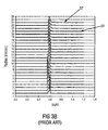
- Fig. 3a shows a DMD pulse trace demonstrating the modal structure of a multimode optical fiber (MMF) in an unbent condition as defined by the TIA/EIA-455-220 Standard. Notice the outer mode structure between radial positions 21 micron (shown at 31) and 24 micron (shown at 32). One can see that at these positions, multiple pulses begin to appear.
- MMF multimode optical fiber
- Fig. 3b is a DMD pulse trace demonstrating the modal structure of the same MMF shown in Fig. 3a except bent around a 12.8 mm diameter mandrel (defined here as the tightly bent condition).
- the outer mode structure between radial positions 21 micron (shown at 31') and 24 micron (shown at 32') has undergone a significant change between the unbent condition of Fig.3a and the bent condition.
- the pulses shown between 21 and 24 microns in Fig. 3b have diminished significantly, thus showing a substantial loss in signal power.
- Figs. 4a and 4b demonstrate that the modal structure for multimode fiber designs according to this invention does not change when bent tightly compared to the unbent condition.
- Fig. 4a shows a DMD pulse trace demonstrating the modal structure of MMF made in accordance with an embodiment of the invention.
- the pulse trace of the MMF is shown in Fig. 4a in the unbent condition. Notice the outer mode structure between radial positions 21 micron (shown at 41) and 24 micron (shown at 42). Similar to the DMD pulse trace shown in Fig. 3a , pulses begin to appear in the outer mode structure.
- Fig. 4b shows a corresponding DMD pulse trace demonstrating the modal structure of the same MMF as shown in Fig. 4a , except bent around a 12.8 mm diameter mandrel (the tightly bent condition). Notice the outer mode structure between radial positions 21 micron (shown at 41') and 24 micron (shown at 42') remains unchanged between the unbent and bent conditions. Thus not only is the power loss of the MMF shown in Figs. 4a and 4b minimal in the bent state, but the original modal structure remains essentially unchanged and intact.
- Fig. 5 a comparison of the measured added power loss for the MMF fiber (upper curve) vs. standard fiber (lower curve) is illustrated in Fig. 5 .
- the measurement is of the bend loss of each fiber with 2 turns around a 10 mm diameter mandrel.
- the improved multimode optical fibers of the invention need not be restricted to short jumpers.
- This optical fiber enables applications in, for example, high transmission links; up to 2km at 1 Gb/s, up to 550m at 10Gb/s, and estimated up to 100m at 40 Gb/s or 100 Gb/s.
- Table 1 provides recommended parameters associated with the refractive-index profile shown in Fig. 1 . Within the ranges provided for these parameters, multimode optical fibers with high bandwidth and ultra-low bend loss may be simultaneously achieved.
- TABLE 1 Designation Parameter Minimum Maximum Optimum a1 Core radius ⁇ m 7 50 25 +/- 4 (a2-a1)/a1 Ratio 0.1 0.7 0.2 +/- 0.1 (a3-a2)/a1 Ratio 0.3 0.6 0.4 +/- 0.1 a4 Clad.
- the trench width (expressed in Table I as normalized to the core radius by the equation (a 3 - a 2 )/a 1 ) was found to be especially important in determining the bend mode preservation of optical fibers. For example, selecting the midpoint of the range for core radius (28.5 microns) of the ranges in Table I, when the minimum value for the parameter (a 3 - a 2 )/a 1 ) is 0.3 the corresponding trench width is 8.55 microns. Expressed as the area of the trench in a cross section of the optical fiber the area is 1913 microns 2 .
- optical fibers exhibiting the best mode preservation performance had a core radius in the range of 22 to 28 microns, but that a properly designed MMF with a core radius in the range 7-50 microns will also exhibit modal structure integrity.
- the properties of the trench are also considered important parameters in designing a BMP.
- the trench width T W should be at least 2.5 microns, and preferably between 10 and 13 microns.
- T A Expressed in terms of trench area, T A , a range of 1500 to 3500 microns 2 is recommended, and preferably the range is 2000 to 2900 microns 2 .
- T A a range of 500 to 3500 microns 2 is recommended, and preferably the range is 2000 to 2900 microns 2 .
- the core delta n in this work is between 0.0125 and 0.016.
- the trench depth (index depth) appears to be a less vital parameter than the width, i.e., larger variations appear to be useful.
- a trench depth (index difference) that is lower than the inner cladding (d 2 ) by a value of 0.0025 to 0.012 is recommended, with a preferred trench depth being between 0.003 to 0.008 lower than the inner cladding (d 2 ).
- the difference is measured from the next adjacent inner cladding.
- Refractive index differences expressed in this specification refer to index differences based on the index of silica (1.46).
- optical fibers described above may be fabricated using any of a variety of known optical fiber manufacturing techniques, for example, Outside Vapor Deposition (OVD), Chemical Vapor Deposition (CVD), Modified Chemical Vapor Deposition (MCVD), Vapor Axial Deposition (VAD), Plasma enhanced CVD (PCVD), etc.
- OCVD Outside Vapor Deposition
- CVD Chemical Vapor Deposition
- MCVD Modified Chemical Vapor Deposition
- VAD Vapor Axial Deposition
- PCVD Plasma enhanced CVD
Landscapes
- Physics & Mathematics (AREA)
- General Physics & Mathematics (AREA)
- Optics & Photonics (AREA)
- Chemical & Material Sciences (AREA)
- Dispersion Chemistry (AREA)
- Mechanical Coupling Of Light Guides (AREA)
- Optical Fibers, Optical Fiber Cores, And Optical Fiber Bundles (AREA)
- Optical Communication System (AREA)
- Optical Couplings Of Light Guides (AREA)
Abstract
Description
- This application claims the benefit of Provisional Application Serial Number
61097639, filed September 17, 2008 - This invention relates to a family of designs for optical fibers having robust optical transmission characteristics. More specifically it relates to optical fibers designed to control bend loss while maintaining the modal structure and bandwidth of the fibers.
- The tendency of optical fibers to leak optical energy when bent has been known since the infancy of the technology. It is well known that light follows a straight path but can be guided to some extent by providing a path, even a curved path, of high refractive index material surrounded by material of lower refractive index. However, in practice that principle is limited, and optical fibers often have bends with a curvature that exceeds the ability of the light guide to contain the light.
- Controlling transmission characteristics when bent is an issue in nearly every practical optical fiber design. The initial approach, and still a common approach, is to prevent or minimize physical bends in the optical fiber. While this can be largely achieved in long hauls by designing a robust cable, or in shorter hauls by installing the optical fibers in microducts, in all cases the optical fiber must be terminated at each end. Thus even under the most favorable conditions, bending, often severe bending, is encountered at the optical fiber terminals.
- Controlling bend loss can also be addressed by the physical design of the optical fiber itself. Some optical fibers are inherently more immune to bend loss than others. This was recognized early, and most optical fibers are now specifically designed for low loss. The design features that are typically effective for microbend loss control involve the properties of the optical fiber cladding, usually the outer cladding. Thus ring features or trench features, or combinations thereof, are commonly found at the outside of the optical fiber refractive index profiles to control bend losses. See for example, United States Patents
4,691,990 and4,852,968 , both incorporated herein by reference. - Performance issues for optical fibers under bend conditions have generally been considered to involve generalized optical power loss, due to leakage of light from the optical fiber at the location of the bend. In most cases, the influence of modal structure changes on bend loss is overlooked.
- In single mode optical fibers general power loss is the primary consideration, because all leakage involves light in the fundamental mode of the optical fiber. However, in multimode optical fiber the modal structure affects the loss, with higher order modes suffering more loss than lower order modes. In addition, bends in the optical fiber cause modes to transform and mix. Accordingly, while a signal in a lower order mode may survive some bending, if it is converted to a higher order mode it will be more susceptible to bending loss.
- The combination of higher order and lower order modes in a multimode optical fiber determines the bandwidth, and thus the signal carrying capacity, of the optical fiber. Bending multimode optical fiber may reduce the signal carrying capacity of the optical system.
- The property of differential mode loss in multimode optical fibers can be more serious than generalized optical loss in single mode optical fibers. The latter can be addressed using low cost power amplifiers. However, differential mode loss in multimode optical fibers can lead to complete loss of signals propagating in higher order modes.
- We have designed multimode optical fibers that largely preserve the modal structure, and thus the bandwidth, of the optical fiber even in the presence of severe bending.
-
-
Fig. 1 is a diagram of an optical fiber refractive index profile showing designations for design parameters used in accordance with an embodiment(s) described below. The figure does not represent any dimensional scale; -
Fig. 2 is a schematic diagram of an apparatus for measuring Differential Mode Delay (DMD), a property used for evaluating the performance of the optical fibers of the invention; -
Figs. 3a and3b are DMD pulse traces showing the effect of bending on a conventional multimode optical fiber; -
Figs. 4a and4b , are DMD traces, to be compared withFigs. 3a and3b , showing the effect of bending on a multimode optical fiber of the invention; -
Fig. 5 is a plot of loss vs. wavelength comparing two multimode optical fibers, one a conventional optical fiber and the other designed according to the invention. - With reference to
Fig. 1 , dimensional design parameters relevant to the practice of the invention are shown. The vertical reference line, line d1, represents the center of the multimode optical fiber. The same proportionate profile, with different absolute values, will characterize the preforms used to manufacture the optical fibers. - It was discovered that for specific controlled design ratios and dimensions multimode optical fibers can be produced that are essentially immune to moderately severe bends. The modal structure is also largely unaffected by bending, thus leaving the optical fiber bandwidth essentially unimpaired. Ordinary optical fibers demonstrate significant modal structure change when bent because the high order modes escape into the cladding and mid-order modes mix with into high-order modes causing significant changes in the optical fiber bandwidth. These changes are typically measured as differential mode delay (DMD). DMD techniques and DMD measurements, as related to the invention, will be described in more detail below.
- Typical optical fibers, and those to which this invention pertains, have a multimode graded index core with a maximum refractive index in the center of the core and with a decreasing refractive index toward the core/cladding boundary. The decreasing refractive index generally follows a parabolic curve defined by the following equations:


- Parameters in the following description relate to those indicated in
Fig. 1 . The quantities d1 and d2 are the refractive indices of the core at r = 0, and r = a1, respectively. The quantity a1 is the maximum core radius and represents the core to clad boundary. The value α is the core shape profile parameter and defines the shape of the graded refractive index profile. The core is surrounded with cladding of radius denoted by a2. For conventional multimode fibers, the refractive index is maintained at a value of d2 in the radial range between a1 and a2. - A specific design feature of this invention is that a portion within the cladding region near the core-cladding boundary (denoted between radial position a2 and a3 in
Figure 1 ), referred to herein as a "trench", has a refractive index value of d3 that is different from d2, with a closely controlled width (a3-a2) within the cladding region. Additionally, the outer cladding refractive index d4 may be different from the inner value as denoted by d2. This negative refractive index region (trench) having depths of index (d3-d2, d3-d4), width (a3-a2), together with its location relative to the graded index core (a2-a1) contributes to preserving the modal structure of the inventive fiber when the fiber is tightly bent (as defined later in this description). Thus a new parameter for optical fiber performance is realized and is designated "bend mode performance" ("BMP"), where BMP is the absolute difference between the 0-23 micron DMD in a bent state and in an unbent state. As defined by the DMD test procedure known as the TIA-FOTP-220 Standard, both the BMP and DMD parameters are expressed in picoseconds per meter, or ps/m. - In formulating designs meeting the inventive criteria, the properties of the trench, in particular the trench width a3 - a2 and the shoulder width a2-a1 were found to have a large effect on the BMP of optical fibers. In fact, within specific ranges of trench widths and shoulder widths, the mode structure of the optical fiber can remain essentially unchanged even when subjected to extreme bending.
- As mentioned previously, relevant changes are typically measured as differential mode delay (DMD). DMD is the difference in propagation time between light energies traveling along different modes in the core of a multimode optical fiber. Multimode optical fiber supports multiple light paths, or modes, that carry light from the transmitter to the receiver. When the energy for a laser pulse is transmitted into the optical fiber, it divides into the different paths. As the energy travels along the multimode optical fiber, DMD will cause the pulse to spread before reaching the receiver. If pulses spread excessively, they may run together. When that occurs, the receiver is not able to discern digital ones from zeros, and the link may fail. This is a problem for 1 Gb/s systems, and limits existing 10 Gb/s systems, and anticipated 40 and 100 Gb/s systems, to only modest distances using conventional multimode fiber. Multimode optical fiber DMD is measured in pico-seconds per meter (ps/m) using an OFS-Fitel developed high-resolution process. This process transmits very short, high-powered 850 nm pulses at many positions, separated by very small steps, across the core of the optical fiber. The received pulses are plotted and the data is used with specially developed OFS software to represent the DMD.
- OFS-Fitel pioneered the use of high-resolution DMD as a quality control measure in 1998 to ensure laser bandwidth of production multimode fibers. High-resolution DMD was adopted by international standards committees as the most reliable predictor of laser bandwidth for 10 Gb/s, and emerging 40 and 100 Gb/s, multimode optical fiber systems. OFS-Fitel co-authored the DMD test procedure known as TIA/EIA-455-220. That procedure has become an industry standard and is widely used on production optical fiber to assure reliable system performance for 1 and 10 Gb/s systems. The procedure is also being incorporated in the standards for 40 and 100 Gb/s systems of the future.
- The TIA/EIA-455-220 test procedure is schematically represented in
Fig. 2 . Thecore 23 of the multimode fiber to be tested is scanned radially with a single-mode fiber 22 using 850nmlaser emitting pulses 21. The corresponding output pulses at the other end of the fiber core are recorded integrally by the high speed optical receiver on the basis of their locations in relation to the radial position of the single mode fiber. This provides precise information on the modal delay differences between the selectively-excited mode groups at the various radial offsets. The DMD scans are then evaluated on the basis of the multiple scans. - DMD scan data is shown in
Figs. 3a ,3b ,4a , and4b . -
Figs. 3a and3b demonstrate how the modal structure in other multimode fiber designs changes when bent tightly compared to the unbent condition. -
Fig. 3a shows a DMD pulse trace demonstrating the modal structure of a multimode optical fiber (MMF) in an unbent condition as defined by the TIA/EIA-455-220 Standard. Notice the outer mode structure betweenradial positions 21 micron (shown at 31) and 24 micron (shown at 32). One can see that at these positions, multiple pulses begin to appear. -
Fig. 3b is a DMD pulse trace demonstrating the modal structure of the same MMF shown inFig. 3a except bent around a 12.8 mm diameter mandrel (defined here as the tightly bent condition). Here the outer mode structure betweenradial positions 21 micron (shown at 31') and 24 micron (shown at 32') has undergone a significant change between the unbent condition ofFig.3a and the bent condition. Specifically, the pulses shown between 21 and 24 microns inFig. 3b have diminished significantly, thus showing a substantial loss in signal power. - In the comparison of
Figs. 3a and3b , it is evident that the outer mode structure and the DMD value computed for the 0-23 radial have changed dramatically. In addition, the power traveling in the outer modes (at 19 microns and beyond) has dropped significantly, suggesting that the modal energy has been redistributed and more power is escaping into cladding modes. This redistribution of modal energy has two effects. One is that the fiber loss, when bent substantially, increases, as is well known. However, not observed prior to this invention are the effects on modal structure relative to the bent state. - In bit error rate (BER) systems testing, it has been shown that the modal bandwidth and additional loss in other MMF designs and in standard fibers, results in significant penalties that cause the link to fail (>10-12 BER) when measured under tight bends. With fibers made by the present invention, it has been shown that the penalty in BER systems testing is greatly minimized compared to tests done with other MMF and standard fibers, and the link operates with better than 10-12 BER.
-
Figs. 4a and4b demonstrate that the modal structure for multimode fiber designs according to this invention does not change when bent tightly compared to the unbent condition. -
Fig. 4a shows a DMD pulse trace demonstrating the modal structure of MMF made in accordance with an embodiment of the invention. The pulse trace of the MMF is shown inFig. 4a in the unbent condition. Notice the outer mode structure betweenradial positions 21 micron (shown at 41) and 24 micron (shown at 42). Similar to the DMD pulse trace shown inFig. 3a , pulses begin to appear in the outer mode structure. -
Fig. 4b shows a corresponding DMD pulse trace demonstrating the modal structure of the same MMF as shown inFig. 4a , except bent around a 12.8 mm diameter mandrel (the tightly bent condition). Notice the outer mode structure betweenradial positions 21 micron (shown at 41') and 24 micron (shown at 42') remains unchanged between the unbent and bent conditions. Thus not only is the power loss of the MMF shown inFigs. 4a and4b minimal in the bent state, but the original modal structure remains essentially unchanged and intact. - Having preserved the modal structure, a comparison of the measured added power loss for the MMF fiber (upper curve) vs. standard fiber (lower curve) is illustrated in
Fig. 5 . The measurement is of the bend loss of each fiber with 2 turns around a 10 mm diameter mandrel. - It should be evident that, due to the preservation of high bandwidth in addition to low bend loss, the improved multimode optical fibers of the invention need not be restricted to short jumpers. This optical fiber enables applications in, for example, high transmission links; up to 2km at 1 Gb/s, up to 550m at 10Gb/s, and estimated up to 100m at 40 Gb/s or 100 Gb/s.
- Table 1 provides recommended parameters associated with the refractive-index profile shown in
Fig. 1 . Within the ranges provided for these parameters, multimode optical fibers with high bandwidth and ultra-low bend loss may be simultaneously achieved.TABLE 1 Designation Parameter Minimum Maximum Optimum a1 Core radius µm 7 50 25 +/- 4 (a2-a1)/a1 Ratio 0.1 0.7 0.2 +/- 0.1 (a3-a2)/a1 Ratio 0.3 0.6 0.4 +/- 0.1 a4 Clad. radius µm 30 250 62.5 +/- 20 d1-d4 Index Δ -0.019 0.032 0.0137 +/- 0.01 d2-d4 Index Δ -0.01 0.01 0 +/-0.005 d3-d4 Index Δ -0.05 -0.0025 -0.011 +/- 0.008 d4 Index 1.397 1.511 1.46 +/- 0.03 Profile shape Alpha 1.6 2.2 2.08 +/- 0.12 - As mentioned earlier, one of these parameters, the trench width (expressed in Table I as normalized to the core radius by the equation (a3 - a2)/a1) was found to be especially important in determining the bend mode preservation of optical fibers. For example, selecting the midpoint of the range for core radius (28.5 microns) of the ranges in Table I, when the minimum value for the parameter (a3 - a2)/a1) is 0.3 the corresponding trench width is 8.55 microns. Expressed as the area of the trench in a cross section of the optical fiber the area is 1913 microns2.
- The following specific examples give parameters for optical fibers with demonstrated excellent BMP. Dimensions are in micrometers; area in micrometers squared.
EXAMPLE I Designation Parameter Value a1 Core radius 26.12 a2 Trench start 28.85 a3 Trench end 38.9 a4 Clad radius 62.5 d1 Index 1.472 d2 Index 1.457 d3 Index 1.449 d4 Index 1.449 Profile shape Alpha 2.08 TW Trench width 10.05 TA Trench area 2139 EXAMPLE II Designation Parameter Value a1 Core radius 28.4 a2 Trench start 28.81 a3 Trench end 40.71 a4 Clad radius 62.5 d1 Index 1.472 d2 Index 1.457 d3 Index 1.449 d4 Index 1.457 Profile shape Alpha 2.08 Tw Trench width 11.9 TA Trench area 2608 EXAMPLE III Designation Parameter Value a1 Core radius 24.4 a2 Trench start 28 a3 Trench end 40.72 a4 Clad radius 62.5 d1 Index 1.470 d2 Index 1.457 d3 Index 1.449 d4 Index 1.457 Profile shape Alpha 2.08 TW Trench width 12.72 TA Trench area 2746 EXAMPLE IV Designation Parameter Value a1 Core radius 25 a2 Trench start 25.5 a3 Trench end 36.9 a4 Clad radius 62.5 d1 Index 1.472 d2 Index 1.457 d3 Index 1.449 d4 Index 1.457 Profile shape Alpha 2.08 TW Trench width 11.4 TA Trench area 2235 EXAMPLE V Designation Parameter Value a1 Core radius 25 a2 Trench start 29.4 a3 Trench end 40.75 a4 Clad radius 62.5 d1 Index 1.472 d2 Index 1.457 d3 Index 1.449 d4 Index 1.457 Profile shape Alpha 2.08 TW Trench width 11.35 TA Trench area 2501 EXAMPLE VI Designation Parameter Value a1 Core radius 25 a2 Trench start 27.7 a3 Trench end 39.1 a4 Clad radius 62.5 d1 Index 1.472 d2 Index 1.457 d3 Index 1.449 d4 Index 1.457 Profile shape Alpha 2.08 Tw Trench width 11.4 TA Trench area 2391 EXAMPLE VII Designation Parameter Value a1 Core radius 25 a2 Trench start 30 a3 Trench end 40 a4 Clad radius 62.5 d1 Index 1.472 d2 Index 1.457 d3 Index 1.446 d4 Index 1.457 Profile shape Alpha 2.08 TW Trench width 10 TA Trench area 2200 EXAMPLE VIII Designation Parameter Value a1 Core radius 23.5 a2 Trench start 28 a3 Trench end 38.23 a4 Clad radius 62.5 d1 Index 1.470 d2 Index 1.457 d3 Index 1.449 d4 Index 1.457 Profile shape Alpha 2.08 TW Trench width 10.23 TA Trench area 2129 - The values given in these tables are precise values. However, it will be understood by those skilled in the art that minor departures, e.g. +/- 2%, will still provide performance results comparable to those indicated below.
- To demonstrate the effectiveness of these optical fiber designs, the BMP was measured for each Example above and is given in the following table, Table II. The units are picoseconds per meter.
Table II Example Condition MW23 BMP 1 Unbent 0.168 0.009 1 Bent 0.159 2 Unbent 0.159 -0.002 2 Bent 0.161 3 Unbent 0.298 0.069 3 Bent 0.229 4 Unbent 0.884 0,054 4 Bent 0.83 5 Unbent 0.193 0.026 5 Bent 0.167 6 Unbent 0.582 0.188 6 Bent 0.394 7 Unbent 0.123 0.004 7 Bent 0.119 8 Unbent 0.291 0.06 8 Bent 0.231 - Expressed in terms of trench area, TA , a range of 1500 to 3500 microns2 is recommended, and preferably the range is 2000 to 2900 microns2.
- The discovery of this narrow range, in which optical fibers may be designed that show excellent BMP, is highly unexpected. The design goal of producing optical fibers that exhibit this unusual behavior is itself considered to be novel in optical fiber technology. Prior to demonstrating the BMP of the eight examples described above there existed no indication in the art that optical fibers with this BMP were possible. The data provided in Table II suggests a target figure of merit for BMP. For most of the examples, the absolute variation in the 0-23 um DMD values between bent and unbent conditions is within the range of 0 to 0.069 picoseconds per meter. Based on this measured performance data, a target figure of merit is an absolute value less than 0.07 picoseconds per meter, and preferably less than 0.02 picoseconds per meter.
- Expressed in terms of trench area, TA, a range of 500 to 3500 microns2 is recommended, and preferably the range is 2000 to 2900 microns2.
- The core delta n in this work is between 0.0125 and 0.016. The trench depth (index depth) appears to be a less vital parameter than the width, i.e., larger variations appear to be useful. A trench depth (index difference) that is lower than the inner cladding (d2) by a value of 0.0025 to 0.012 is recommended, with a preferred trench depth being between 0.003 to 0.008 lower than the inner cladding (d2). The difference is measured from the next adjacent inner cladding. Refractive index differences expressed in this specification refer to index differences based on the index of silica (1.46).
- The optical fibers described above may be fabricated using any of a variety of known optical fiber manufacturing techniques, for example, Outside Vapor Deposition (OVD), Chemical Vapor Deposition (CVD), Modified Chemical Vapor Deposition (MCVD), Vapor Axial Deposition (VAD), Plasma enhanced CVD (PCVD), etc.
- Various additional modifications of this invention will occur to those skilled in the art. All deviations from the specific teachings of this specification that basically rely on the principles and their equivalents through which the art has been advanced are properly considered within the scope of the invention as described and claimed.
Claims (22)
Applications Claiming Priority (2)
| Application Number | Priority Date | Filing Date | Title |
|---|---|---|---|
| US9763908P | 2008-09-17 | 2008-09-17 | |
| US12/583,212 US8520994B2 (en) | 2008-09-17 | 2009-08-17 | Bandwidth-maintaining multimode optical fibers |
Publications (2)
| Publication Number | Publication Date |
|---|---|
| EP2166386A1 true EP2166386A1 (en) | 2010-03-24 |
| EP2166386B1 EP2166386B1 (en) | 2014-04-30 |
Family
ID=41404305
Family Applications (1)
| Application Number | Title | Priority Date | Filing Date |
|---|---|---|---|
| EP09011817.5A Active EP2166386B1 (en) | 2008-09-17 | 2009-09-16 | Bandwidth-maintaining multimode optical fibers |
Country Status (4)
| Country | Link |
|---|---|
| US (2) | US8520994B2 (en) |
| EP (1) | EP2166386B1 (en) |
| JP (1) | JP5570166B2 (en) |
| CN (2) | CN104020520B (en) |
Cited By (13)
| Publication number | Priority date | Publication date | Assignee | Title |
|---|---|---|---|---|
| DE202010017188U1 (en) | 2010-11-04 | 2011-04-21 | J-Plasma Gmbh | Optical waveguide and semifinished product for producing an optical waveguide with bending-optimized properties |
| DE202011103554U1 (en) | 2010-10-19 | 2012-01-19 | J-Fiber Gmbh | Preform for producing an optical waveguide |
| EP2447749A1 (en) | 2010-10-18 | 2012-05-02 | Draka Comteq B.V. | A multimode optical fiber insensitive to bending losses |
| DE102011009242A1 (en) | 2010-11-04 | 2012-05-10 | J-Plasma Gmbh | Optical waveguide and semifinished product for producing an optical waveguide with bending-optimized properties |
| EP2541292A1 (en) | 2011-07-01 | 2013-01-02 | Draka Comteq BV | Multimode optical fibre |
| DE102011052197A1 (en) | 2011-07-27 | 2013-01-31 | J-Plasma Gmbh | Semi-finished material e.g. sensor fiber, for manufacturing optical waveguide, has refraction index trench profile determined in region of cladding zone by lower and/or upper envelopes and zone function oscillating between envelopes |
| EP2642322A1 (en) * | 2012-03-23 | 2013-09-25 | Draka Comteq B.V. | Bend-resistant multimode optical fiber |
| EP2706387A1 (en) * | 2012-09-05 | 2014-03-12 | OFS Fitel, LLC | Multiple LP-mode fiber designs for mode-division multiplexing |
| EP2758817A4 (en) * | 2011-09-21 | 2015-06-24 | Ofs Fitel Llc | Optimized ultra large area optical fibers |
| WO2016070946A1 (en) | 2014-11-07 | 2016-05-12 | Prysmian S.P.A. | Multimode optical fiber for power-over-fiber applications |
| US9341771B2 (en) | 2011-03-24 | 2016-05-17 | Draka Comteq, B.V. | Bend-resistant multimode optical fiber |
| EP3029498A1 (en) * | 2014-03-07 | 2016-06-08 | Fujikura Ltd. | Multi-core fiber |
| US9405062B2 (en) | 2011-04-27 | 2016-08-02 | Draka Comteq B.V. | High-bandwidth, radiation-resistant multimode optical fiber |
Families Citing this family (36)
| Publication number | Priority date | Publication date | Assignee | Title |
|---|---|---|---|---|
| NL1024015C2 (en) | 2003-07-28 | 2005-02-01 | Draka Fibre Technology Bv | Multimode optical fiber provided with a refractive index profile, optical communication system using this and method for manufacturing such a fiber. |
| US20070003198A1 (en) * | 2005-06-29 | 2007-01-04 | Lance Gibson | Low loss optical fiber designs and methods for their manufacture |
| FR2893149B1 (en) * | 2005-11-10 | 2008-01-11 | Draka Comteq France | OPTICAL FIBER MONOMODE. |
| FR2922657B1 (en) | 2007-10-23 | 2010-02-12 | Draka Comteq France | MULTIMODE FIBER. |
| FR2932932B1 (en) * | 2008-06-23 | 2010-08-13 | Draka Comteq France Sa | MULTIPLEX WAVE LENGTH OPTIC SYSTEM WITH MULTIMODE OPTIC FIBERS |
| FR2933779B1 (en) | 2008-07-08 | 2010-08-27 | Draka Comteq France | MULTIMODE OPTIC FIBERS |
| FR2940839B1 (en) | 2009-01-08 | 2012-09-14 | Draka Comteq France | INDEX GRADIENT MULTIMODAL OPTICAL FIBER, METHODS FOR CHARACTERIZATION AND MANUFACTURE OF SUCH A FIBER |
| FR2946436B1 (en) | 2009-06-05 | 2011-12-09 | Draka Comteq France | MULTIMODE OPTICAL FIBER WITH LARGE BANDWIDTH WITH AN OPTIMIZED HEAT-SLEEVE INTERFACE |
| FR2949870B1 (en) * | 2009-09-09 | 2011-12-16 | Draka Compteq France | MULTIMODE OPTICAL FIBER HAVING IMPROVED BENDING LOSSES |
| FR2953029B1 (en) | 2009-11-25 | 2011-11-18 | Draka Comteq France | MULTIMODE OPTICAL FIBER WITH LARGE BANDWIDTH WITH AN OPTIMIZED HEAT-SLEEVE INTERFACE |
| FR2957153B1 (en) | 2010-03-02 | 2012-08-10 | Draka Comteq France | MULTIMODE OPTICAL FIBER WITH BROAD BANDWIDTH AND LOW BENDBACK LOSSES |
| FR2953606B1 (en) | 2009-12-03 | 2012-04-27 | Draka Comteq France | MULTIMODE OPTICAL FIBER WITH BROAD BANDWIDTH AND LOW BENDBACK LOSSES |
| FR2953605B1 (en) | 2009-12-03 | 2011-12-16 | Draka Comteq France | MULTIMODE OPTICAL FIBER WITH BROAD BANDWIDTH AND LOW BENDBACK LOSSES |
| FR2953030B1 (en) | 2009-11-25 | 2011-11-18 | Draka Comteq France | MULTIMODE OPTICAL FIBER WITH LARGE BANDWIDTH WITH AN OPTIMIZED HEAT-SLEEVE INTERFACE |
| US9014525B2 (en) | 2009-09-09 | 2015-04-21 | Draka Comteq, B.V. | Trench-assisted multimode optical fiber |
| FR2950156B1 (en) | 2009-09-17 | 2011-11-18 | Draka Comteq France | MULTIMODE OPTIC FIBER |
| EP2534511B1 (en) | 2010-02-09 | 2024-10-30 | OFS Fitel, LLC | Improvement of dmd performance in bend optimized multimode fiber |
| EP2482106B1 (en) | 2011-01-31 | 2014-06-04 | Draka Comteq B.V. | Multimode fiber |
| FR2971061B1 (en) | 2011-01-31 | 2013-02-08 | Draka Comteq France | BROAD BANDWIDTH OPTICAL FIBER WITH LOW CURB LOSSES |
| EP2506044A1 (en) | 2011-03-29 | 2012-10-03 | Draka Comteq B.V. | Multimode optical fiber |
| DE102011109838A1 (en) * | 2011-05-27 | 2012-11-29 | J-Plasma Gmbh | optical fiber |
| CN102193142B (en) * | 2011-06-28 | 2013-06-26 | 长飞光纤光缆有限公司 | Bending-resistant large core high numerical aperture multimode fiber |
| US8718431B2 (en) * | 2011-09-21 | 2014-05-06 | Ofs Fitel, Llc | Optimized ultra large area optical fibers |
| US8687932B2 (en) * | 2011-09-21 | 2014-04-01 | Ofs Fitel, Llc | Optimized ultra large area optical fibers |
| US8565566B2 (en) | 2011-10-05 | 2013-10-22 | Sumitomo Electric Industries, Ltd. | Multi-mode optical fiber |
| US8565567B2 (en) | 2011-11-23 | 2013-10-22 | Sumitomo Electric Industries, Ltd. | Multi-mode optical fiber |
| US9709731B2 (en) | 2012-09-05 | 2017-07-18 | Ofs Fitel, Llc | Multiple LP-mode fiber designs for mode-division multiplexing |
| US9671552B2 (en) * | 2012-09-05 | 2017-06-06 | Ofs Fitel, Llc | 9 LP-mode fiber designs for mode-division multiplexing |
| NO3014320T3 (en) | 2013-06-26 | 2018-03-10 | ||
| JP6664327B2 (en) | 2014-01-31 | 2020-03-13 | オーエフエス ファイテル,エルエルシー | Design and manufacture of multimode optical fiber |
| CN104834053A (en) * | 2014-02-08 | 2015-08-12 | 住友电气工业株式会社 | MMF and manufacturing method thereof |
| CN105204111A (en) * | 2015-10-28 | 2015-12-30 | 长飞光纤光缆股份有限公司 | Multimode optical fiber with relatively low intermodal dispersion |
| CN105577299B (en) * | 2015-12-24 | 2018-07-27 | 中国电子科技集团公司第四十一研究所 | A kind of bandwidth for multimode optical fibers measuring device and method |
| CN108333671B (en) * | 2018-02-01 | 2019-12-03 | 烽火通信科技股份有限公司 | Anti-bending multimode fiber |
| CN108983350B (en) * | 2018-09-25 | 2020-09-22 | 长飞光纤光缆股份有限公司 | Small-core-diameter graded-index optical fiber |
| CN111366180B (en) * | 2020-05-08 | 2022-02-15 | 中天科技光纤有限公司 | External parameter measuring method based on optical fiber sensor |
Citations (8)
| Publication number | Priority date | Publication date | Assignee | Title |
|---|---|---|---|---|
| US4691990A (en) | 1984-11-13 | 1987-09-08 | American Telephone And Telegraph Company, At&T Bell Laboratories | Optical fiber with depressed index outer cladding |
| US4852968A (en) | 1986-08-08 | 1989-08-01 | American Telephone And Telegraph Company, At&T Bell Laboratories | Optical fiber comprising a refractive index trench |
| US20050008312A1 (en) * | 2003-07-11 | 2005-01-13 | Yun-Geun Jang | Graded-index optical fiber |
| EP1498753A2 (en) * | 2003-07-18 | 2005-01-19 | Fujikura Ltd. | Graded-index multimode fiber and manufacturing method therefor |
| EP1538467A1 (en) * | 2002-09-12 | 2005-06-08 | Asahi Glass Company Ltd. | Plastic optical fiber |
| EP1548961A1 (en) * | 2003-12-23 | 2005-06-29 | Draka Comteq B.V. | Dispersion managed HOM multimode optical fibre. |
| WO2007043060A1 (en) * | 2005-10-07 | 2007-04-19 | Sterlite Optical Technologies Ltd. | Optical fiber having higher bandwidth and method for producing the same |
| US20080166094A1 (en) * | 2007-01-08 | 2008-07-10 | Corning Incorporated | Bend resistant multimode optical fiber |
Family Cites Families (8)
| Publication number | Priority date | Publication date | Assignee | Title |
|---|---|---|---|---|
| US7187833B2 (en) * | 2004-04-29 | 2007-03-06 | Corning Incorporated | Low attenuation large effective area optical fiber |
| US7646955B2 (en) * | 2004-07-26 | 2010-01-12 | Corning Incorporated | Multimode optical fiber with low differential mode delay |
| US7526169B2 (en) * | 2006-11-29 | 2009-04-28 | Corning Incorporated | Low bend loss quasi-single-mode optical fiber and optical fiber line |
| EP2115503A2 (en) * | 2007-02-28 | 2009-11-11 | Corning Incorporated | Optical fiber with large effective area |
| WO2008136918A2 (en) * | 2007-05-07 | 2008-11-13 | Corning Incorporated | Large effective area fiber |
| US20090169163A1 (en) * | 2007-12-13 | 2009-07-02 | Abbott Iii John Steele | Bend Resistant Multimode Optical Fiber |
| US7773848B2 (en) * | 2008-07-30 | 2010-08-10 | Corning Incorporated | Low bend loss single mode optical fiber |
| US7903918B1 (en) * | 2010-02-22 | 2011-03-08 | Corning Incorporated | Large numerical aperture bend resistant multimode optical fiber |
-
2009
- 2009-08-17 US US12/583,212 patent/US8520994B2/en active Active
- 2009-09-16 EP EP09011817.5A patent/EP2166386B1/en active Active
- 2009-09-16 CN CN201310551704.3A patent/CN104020520B/en active Active
- 2009-09-16 CN CN200910211614.3A patent/CN101738683B/en active Active
- 2009-09-17 JP JP2009215259A patent/JP5570166B2/en active Active
-
2013
- 2013-07-29 US US13/953,470 patent/US20140270670A1/en not_active Abandoned
Patent Citations (8)
| Publication number | Priority date | Publication date | Assignee | Title |
|---|---|---|---|---|
| US4691990A (en) | 1984-11-13 | 1987-09-08 | American Telephone And Telegraph Company, At&T Bell Laboratories | Optical fiber with depressed index outer cladding |
| US4852968A (en) | 1986-08-08 | 1989-08-01 | American Telephone And Telegraph Company, At&T Bell Laboratories | Optical fiber comprising a refractive index trench |
| EP1538467A1 (en) * | 2002-09-12 | 2005-06-08 | Asahi Glass Company Ltd. | Plastic optical fiber |
| US20050008312A1 (en) * | 2003-07-11 | 2005-01-13 | Yun-Geun Jang | Graded-index optical fiber |
| EP1498753A2 (en) * | 2003-07-18 | 2005-01-19 | Fujikura Ltd. | Graded-index multimode fiber and manufacturing method therefor |
| EP1548961A1 (en) * | 2003-12-23 | 2005-06-29 | Draka Comteq B.V. | Dispersion managed HOM multimode optical fibre. |
| WO2007043060A1 (en) * | 2005-10-07 | 2007-04-19 | Sterlite Optical Technologies Ltd. | Optical fiber having higher bandwidth and method for producing the same |
| US20080166094A1 (en) * | 2007-01-08 | 2008-07-10 | Corning Incorporated | Bend resistant multimode optical fiber |
Non-Patent Citations (2)
| Title |
|---|
| ENDO H ET AL: "Modal Bandwidth Enhancement in a Plastic Optical Fiber by W-Refractive Index Profile", JOURNAL OF LIGHTWAVE TECHNOLOGY, IEEE SERVICE CENTER, NEW YORK, NY, US, vol. 23, no. 4, 1 April 2005 (2005-04-01), pages 1754 - 1762, XP011130800, ISSN: 0733-8724 * |
| LINGLE R JNR ET AL: "Multimode fibers optimized for high speed, short reach interconnects", 33RD EUROPEAN CONFERENCE AND EXHIBITION ON OPTICAL COMMUNICATION - ECOC 2007, SEPTEMBER 16 - 20, 2007, BERLIN, GERMANY, VDE VERLAG, DE, 16 September 2007 (2007-09-16), pages 4pp, XP009127374, ISBN: 978-3-8007-3042-1 * |
Cited By (22)
| Publication number | Priority date | Publication date | Assignee | Title |
|---|---|---|---|---|
| US8891074B2 (en) | 2010-10-18 | 2014-11-18 | Draka Comteq, B.V. | Multimode optical fiber insensitive to bending losses |
| EP2447749A1 (en) | 2010-10-18 | 2012-05-02 | Draka Comteq B.V. | A multimode optical fiber insensitive to bending losses |
| DE202011103554U1 (en) | 2010-10-19 | 2012-01-19 | J-Fiber Gmbh | Preform for producing an optical waveguide |
| DE102011014915A1 (en) | 2010-10-19 | 2012-04-19 | J-Fiber Gmbh | Preform used in manufacture of optical waveguide, has thin rods that are formed by twisting primary preform and arranged surrounding preform cladding, where rod cladding is made of silicon dioxide |
| DE102011014915B4 (en) | 2010-10-19 | 2019-01-17 | J-Fiber Gmbh | Process for the production of an optical waveguide with an optimizable macrobending loss and preform for the production of an optical waveguide |
| DE102011009242A1 (en) | 2010-11-04 | 2012-05-10 | J-Plasma Gmbh | Optical waveguide and semifinished product for producing an optical waveguide with bending-optimized properties |
| WO2012084310A1 (en) | 2010-11-04 | 2012-06-28 | J-Plasma Gmbh | Optical waveguide and semifinished product for the production of an optical waveguide having optimized diffraction properties |
| DE202010017188U1 (en) | 2010-11-04 | 2011-04-21 | J-Plasma Gmbh | Optical waveguide and semifinished product for producing an optical waveguide with bending-optimized properties |
| US9671553B2 (en) | 2011-03-24 | 2017-06-06 | Draka Comteq, B.V. | Bend-resistant multimode optical fiber |
| US9341771B2 (en) | 2011-03-24 | 2016-05-17 | Draka Comteq, B.V. | Bend-resistant multimode optical fiber |
| US9405062B2 (en) | 2011-04-27 | 2016-08-02 | Draka Comteq B.V. | High-bandwidth, radiation-resistant multimode optical fiber |
| US8879878B2 (en) | 2011-07-01 | 2014-11-04 | Draka Comteq, B.V. | Multimode optical fiber |
| EP2541292A1 (en) | 2011-07-01 | 2013-01-02 | Draka Comteq BV | Multimode optical fibre |
| DE102011052197A1 (en) | 2011-07-27 | 2013-01-31 | J-Plasma Gmbh | Semi-finished material e.g. sensor fiber, for manufacturing optical waveguide, has refraction index trench profile determined in region of cladding zone by lower and/or upper envelopes and zone function oscillating between envelopes |
| DE102011052197B4 (en) | 2011-07-27 | 2019-08-01 | J-Plasma Gmbh | Fiber optic cables with bending-optimized properties |
| EP2758817A4 (en) * | 2011-09-21 | 2015-06-24 | Ofs Fitel Llc | Optimized ultra large area optical fibers |
| EP2642322A1 (en) * | 2012-03-23 | 2013-09-25 | Draka Comteq B.V. | Bend-resistant multimode optical fiber |
| EP2706387A1 (en) * | 2012-09-05 | 2014-03-12 | OFS Fitel, LLC | Multiple LP-mode fiber designs for mode-division multiplexing |
| EP3029498A1 (en) * | 2014-03-07 | 2016-06-08 | Fujikura Ltd. | Multi-core fiber |
| EP3029498A4 (en) * | 2014-03-07 | 2017-03-29 | Fujikura Ltd. | Multi-core fiber |
| WO2016070946A1 (en) | 2014-11-07 | 2016-05-12 | Prysmian S.P.A. | Multimode optical fiber for power-over-fiber applications |
| US10197725B2 (en) | 2014-11-07 | 2019-02-05 | Prysmian S.P.A | Multimode optical fiber for power-over-fiber applications with specific refraction index profile |
Also Published As
| Publication number | Publication date |
|---|---|
| US20140270670A1 (en) | 2014-09-18 |
| US20100067858A1 (en) | 2010-03-18 |
| CN104020520B (en) | 2017-01-04 |
| CN104020520A (en) | 2014-09-03 |
| CN101738683B (en) | 2014-12-17 |
| US8520994B2 (en) | 2013-08-27 |
| CN101738683A (en) | 2010-06-16 |
| JP2010072647A (en) | 2010-04-02 |
| EP2166386B1 (en) | 2014-04-30 |
| JP5570166B2 (en) | 2014-08-13 |
Similar Documents
| Publication | Publication Date | Title |
|---|---|---|
| EP2166386B1 (en) | Bandwidth-maintaining multimode optical fibers | |
| EP2447749B1 (en) | Method of selecting a multimode optical fibre insensitive to bending losses | |
| EP2211211B1 (en) | Single mode optical fibre | |
| EP2726921B1 (en) | Multimode optical fiber and system incorporating such | |
| EP2259105B1 (en) | Very broad bandwidth multimode optical fibre with an optimized core-cladding interface and reduced cladding effect | |
| US8009950B2 (en) | Multimode fiber | |
| EP2339383B1 (en) | Multimode optical fiber with low bending losses and reduced cladding effect | |
| EP2211212B1 (en) | Single-mode optical fibre having an enlarged effective area | |
| EP2339384B1 (en) | High-bandwidth multimode optical fiber having reduced bending losses | |
| JP5945441B2 (en) | Multimode optical fiber | |
| EP2482106B1 (en) | Multimode fiber | |
| EP2482107B1 (en) | Broad bandwidth multimode optical fiber with low bending losses | |
| EP2503368A1 (en) | Multimode optical fiber with improved bend resistance | |
| KR101673909B1 (en) | Multimode fiber having improved index profile | |
| US9568669B2 (en) | Bandwidth-maintaining multimode optical fibers | |
| EP3577499B1 (en) | Multimode optical fiber optimized to operate around 1060 nm, and corresponding multimode optical system | |
| EP2642322A1 (en) | Bend-resistant multimode optical fiber |
Legal Events
| Date | Code | Title | Description |
|---|---|---|---|
| PUAI | Public reference made under article 153(3) epc to a published international application that has entered the european phase |
Free format text: ORIGINAL CODE: 0009012 |
|
| AK | Designated contracting states |
Kind code of ref document: A1 Designated state(s): AT BE BG CH CY CZ DE DK EE ES FI FR GB GR HR HU IE IS IT LI LT LU LV MC MK MT NL NO PL PT RO SE SI SK SM TR |
|
| AX | Request for extension of the european patent |
Extension state: AL BA RS |
|
| 17P | Request for examination filed |
Effective date: 20100924 |
|
| 17Q | First examination report despatched |
Effective date: 20120402 |
|
| GRAP | Despatch of communication of intention to grant a patent |
Free format text: ORIGINAL CODE: EPIDOSNIGR1 |
|
| INTG | Intention to grant announced |
Effective date: 20131111 |
|
| GRAS | Grant fee paid |
Free format text: ORIGINAL CODE: EPIDOSNIGR3 |
|
| GRAA | (expected) grant |
Free format text: ORIGINAL CODE: 0009210 |
|
| AK | Designated contracting states |
Kind code of ref document: B1 Designated state(s): AT BE BG CH CY CZ DE DK EE ES FI FR GB GR HR HU IE IS IT LI LT LU LV MC MK MT NL NO PL PT RO SE SI SK SM TR |
|
| REG | Reference to a national code |
Ref country code: GB Ref legal event code: FG4D Ref country code: CH Ref legal event code: EP |
|
| REG | Reference to a national code |
Ref country code: AT Ref legal event code: REF Ref document number: 665492 Country of ref document: AT Kind code of ref document: T Effective date: 20140515 |
|
| REG | Reference to a national code |
Ref country code: IE Ref legal event code: FG4D |
|
| REG | Reference to a national code |
Ref country code: DE Ref legal event code: R096 Ref document number: 602009023620 Country of ref document: DE Effective date: 20140612 |
|
| REG | Reference to a national code |
Ref country code: AT Ref legal event code: MK05 Ref document number: 665492 Country of ref document: AT Kind code of ref document: T Effective date: 20140430 |
|
| REG | Reference to a national code |
Ref country code: LT Ref legal event code: MG4D |
|
| REG | Reference to a national code |
Ref country code: NL Ref legal event code: VDEP Effective date: 20140430 |
|
| PG25 | Lapsed in a contracting state [announced via postgrant information from national office to epo] |
Ref country code: BG Free format text: LAPSE BECAUSE OF FAILURE TO SUBMIT A TRANSLATION OF THE DESCRIPTION OR TO PAY THE FEE WITHIN THE PRESCRIBED TIME-LIMIT Effective date: 20140730 Ref country code: FI Free format text: LAPSE BECAUSE OF FAILURE TO SUBMIT A TRANSLATION OF THE DESCRIPTION OR TO PAY THE FEE WITHIN THE PRESCRIBED TIME-LIMIT Effective date: 20140430 Ref country code: IS Free format text: LAPSE BECAUSE OF FAILURE TO SUBMIT A TRANSLATION OF THE DESCRIPTION OR TO PAY THE FEE WITHIN THE PRESCRIBED TIME-LIMIT Effective date: 20140830 Ref country code: NO Free format text: LAPSE BECAUSE OF FAILURE TO SUBMIT A TRANSLATION OF THE DESCRIPTION OR TO PAY THE FEE WITHIN THE PRESCRIBED TIME-LIMIT Effective date: 20140730 Ref country code: NL Free format text: LAPSE BECAUSE OF FAILURE TO SUBMIT A TRANSLATION OF THE DESCRIPTION OR TO PAY THE FEE WITHIN THE PRESCRIBED TIME-LIMIT Effective date: 20140430 Ref country code: CY Free format text: LAPSE BECAUSE OF FAILURE TO SUBMIT A TRANSLATION OF THE DESCRIPTION OR TO PAY THE FEE WITHIN THE PRESCRIBED TIME-LIMIT Effective date: 20140430 Ref country code: GR Free format text: LAPSE BECAUSE OF FAILURE TO SUBMIT A TRANSLATION OF THE DESCRIPTION OR TO PAY THE FEE WITHIN THE PRESCRIBED TIME-LIMIT Effective date: 20140731 Ref country code: LT Free format text: LAPSE BECAUSE OF FAILURE TO SUBMIT A TRANSLATION OF THE DESCRIPTION OR TO PAY THE FEE WITHIN THE PRESCRIBED TIME-LIMIT Effective date: 20140430 |
|
| PG25 | Lapsed in a contracting state [announced via postgrant information from national office to epo] |
Ref country code: SE Free format text: LAPSE BECAUSE OF FAILURE TO SUBMIT A TRANSLATION OF THE DESCRIPTION OR TO PAY THE FEE WITHIN THE PRESCRIBED TIME-LIMIT Effective date: 20140430 Ref country code: PL Free format text: LAPSE BECAUSE OF FAILURE TO SUBMIT A TRANSLATION OF THE DESCRIPTION OR TO PAY THE FEE WITHIN THE PRESCRIBED TIME-LIMIT Effective date: 20140430 Ref country code: AT Free format text: LAPSE BECAUSE OF FAILURE TO SUBMIT A TRANSLATION OF THE DESCRIPTION OR TO PAY THE FEE WITHIN THE PRESCRIBED TIME-LIMIT Effective date: 20140430 Ref country code: HR Free format text: LAPSE BECAUSE OF FAILURE TO SUBMIT A TRANSLATION OF THE DESCRIPTION OR TO PAY THE FEE WITHIN THE PRESCRIBED TIME-LIMIT Effective date: 20140430 Ref country code: ES Free format text: LAPSE BECAUSE OF FAILURE TO SUBMIT A TRANSLATION OF THE DESCRIPTION OR TO PAY THE FEE WITHIN THE PRESCRIBED TIME-LIMIT Effective date: 20140430 Ref country code: LV Free format text: LAPSE BECAUSE OF FAILURE TO SUBMIT A TRANSLATION OF THE DESCRIPTION OR TO PAY THE FEE WITHIN THE PRESCRIBED TIME-LIMIT Effective date: 20140430 |
|
| PG25 | Lapsed in a contracting state [announced via postgrant information from national office to epo] |
Ref country code: PT Free format text: LAPSE BECAUSE OF FAILURE TO SUBMIT A TRANSLATION OF THE DESCRIPTION OR TO PAY THE FEE WITHIN THE PRESCRIBED TIME-LIMIT Effective date: 20140901 |
|
| PG25 | Lapsed in a contracting state [announced via postgrant information from national office to epo] |
Ref country code: EE Free format text: LAPSE BECAUSE OF FAILURE TO SUBMIT A TRANSLATION OF THE DESCRIPTION OR TO PAY THE FEE WITHIN THE PRESCRIBED TIME-LIMIT Effective date: 20140430 Ref country code: CZ Free format text: LAPSE BECAUSE OF FAILURE TO SUBMIT A TRANSLATION OF THE DESCRIPTION OR TO PAY THE FEE WITHIN THE PRESCRIBED TIME-LIMIT Effective date: 20140430 Ref country code: RO Free format text: LAPSE BECAUSE OF FAILURE TO SUBMIT A TRANSLATION OF THE DESCRIPTION OR TO PAY THE FEE WITHIN THE PRESCRIBED TIME-LIMIT Effective date: 20140430 Ref country code: SK Free format text: LAPSE BECAUSE OF FAILURE TO SUBMIT A TRANSLATION OF THE DESCRIPTION OR TO PAY THE FEE WITHIN THE PRESCRIBED TIME-LIMIT Effective date: 20140430 Ref country code: BE Free format text: LAPSE BECAUSE OF FAILURE TO SUBMIT A TRANSLATION OF THE DESCRIPTION OR TO PAY THE FEE WITHIN THE PRESCRIBED TIME-LIMIT Effective date: 20140430 Ref country code: DK Free format text: LAPSE BECAUSE OF FAILURE TO SUBMIT A TRANSLATION OF THE DESCRIPTION OR TO PAY THE FEE WITHIN THE PRESCRIBED TIME-LIMIT Effective date: 20140430 |
|
| REG | Reference to a national code |
Ref country code: DE Ref legal event code: R097 Ref document number: 602009023620 Country of ref document: DE |
|
| PLBE | No opposition filed within time limit |
Free format text: ORIGINAL CODE: 0009261 |
|
| STAA | Information on the status of an ep patent application or granted ep patent |
Free format text: STATUS: NO OPPOSITION FILED WITHIN TIME LIMIT |
|
| PG25 | Lapsed in a contracting state [announced via postgrant information from national office to epo] |
Ref country code: IT Free format text: LAPSE BECAUSE OF FAILURE TO SUBMIT A TRANSLATION OF THE DESCRIPTION OR TO PAY THE FEE WITHIN THE PRESCRIBED TIME-LIMIT Effective date: 20140430 |
|
| 26N | No opposition filed |
Effective date: 20150202 |
|
| PG25 | Lapsed in a contracting state [announced via postgrant information from national office to epo] |
Ref country code: LU Free format text: LAPSE BECAUSE OF FAILURE TO SUBMIT A TRANSLATION OF THE DESCRIPTION OR TO PAY THE FEE WITHIN THE PRESCRIBED TIME-LIMIT Effective date: 20140916 Ref country code: MC Free format text: LAPSE BECAUSE OF FAILURE TO SUBMIT A TRANSLATION OF THE DESCRIPTION OR TO PAY THE FEE WITHIN THE PRESCRIBED TIME-LIMIT Effective date: 20140430 |
|
| REG | Reference to a national code |
Ref country code: CH Ref legal event code: PL |
|
| REG | Reference to a national code |
Ref country code: DE Ref legal event code: R097 Ref document number: 602009023620 Country of ref document: DE Effective date: 20150202 |
|
| REG | Reference to a national code |
Ref country code: IE Ref legal event code: MM4A |
|
| PG25 | Lapsed in a contracting state [announced via postgrant information from national office to epo] |
Ref country code: SI Free format text: LAPSE BECAUSE OF FAILURE TO SUBMIT A TRANSLATION OF THE DESCRIPTION OR TO PAY THE FEE WITHIN THE PRESCRIBED TIME-LIMIT Effective date: 20140430 Ref country code: CH Free format text: LAPSE BECAUSE OF NON-PAYMENT OF DUE FEES Effective date: 20140930 Ref country code: LI Free format text: LAPSE BECAUSE OF NON-PAYMENT OF DUE FEES Effective date: 20140930 |
|
| PG25 | Lapsed in a contracting state [announced via postgrant information from national office to epo] |
Ref country code: IE Free format text: LAPSE BECAUSE OF NON-PAYMENT OF DUE FEES Effective date: 20140916 |
|
| REG | Reference to a national code |
Ref country code: FR Ref legal event code: PLFP Year of fee payment: 7 |
|
| PG25 | Lapsed in a contracting state [announced via postgrant information from national office to epo] |
Ref country code: SM Free format text: LAPSE BECAUSE OF FAILURE TO SUBMIT A TRANSLATION OF THE DESCRIPTION OR TO PAY THE FEE WITHIN THE PRESCRIBED TIME-LIMIT Effective date: 20140430 |
|
| PG25 | Lapsed in a contracting state [announced via postgrant information from national office to epo] |
Ref country code: MT Free format text: LAPSE BECAUSE OF FAILURE TO SUBMIT A TRANSLATION OF THE DESCRIPTION OR TO PAY THE FEE WITHIN THE PRESCRIBED TIME-LIMIT Effective date: 20140430 |
|
| PG25 | Lapsed in a contracting state [announced via postgrant information from national office to epo] |
Ref country code: HU Free format text: LAPSE BECAUSE OF FAILURE TO SUBMIT A TRANSLATION OF THE DESCRIPTION OR TO PAY THE FEE WITHIN THE PRESCRIBED TIME-LIMIT; INVALID AB INITIO Effective date: 20090916 Ref country code: TR Free format text: LAPSE BECAUSE OF FAILURE TO SUBMIT A TRANSLATION OF THE DESCRIPTION OR TO PAY THE FEE WITHIN THE PRESCRIBED TIME-LIMIT Effective date: 20140430 |
|
| REG | Reference to a national code |
Ref country code: FR Ref legal event code: PLFP Year of fee payment: 8 |
|
| REG | Reference to a national code |
Ref country code: FR Ref legal event code: PLFP Year of fee payment: 9 |
|
| PG25 | Lapsed in a contracting state [announced via postgrant information from national office to epo] |
Ref country code: MK Free format text: LAPSE BECAUSE OF FAILURE TO SUBMIT A TRANSLATION OF THE DESCRIPTION OR TO PAY THE FEE WITHIN THE PRESCRIBED TIME-LIMIT Effective date: 20140430 |
|
| REG | Reference to a national code |
Ref country code: FR Ref legal event code: PLFP Year of fee payment: 10 |
|
| P01 | Opt-out of the competence of the unified patent court (upc) registered |
Effective date: 20230411 |
|
| PGFP | Annual fee paid to national office [announced via postgrant information from national office to epo] |
Ref country code: GB Payment date: 20231027 Year of fee payment: 15 |
|
| PGFP | Annual fee paid to national office [announced via postgrant information from national office to epo] |
Ref country code: FR Payment date: 20231025 Year of fee payment: 15 Ref country code: DE Payment date: 20231027 Year of fee payment: 15 |