JP2010072647A - Bandwidth-maintaining multimode optical fiber - Google Patents
Bandwidth-maintaining multimode optical fiber Download PDFInfo
- Publication number
- JP2010072647A JP2010072647A JP2009215259A JP2009215259A JP2010072647A JP 2010072647 A JP2010072647 A JP 2010072647A JP 2009215259 A JP2009215259 A JP 2009215259A JP 2009215259 A JP2009215259 A JP 2009215259A JP 2010072647 A JP2010072647 A JP 2010072647A
- Authority
- JP
- Japan
- Prior art keywords
- optical fiber
- radius
- refractive index
- trench
- microns
- Prior art date
- Legal status (The legal status is an assumption and is not a legal conclusion. Google has not performed a legal analysis and makes no representation as to the accuracy of the status listed.)
- Granted
Links
- 239000013307 optical fiber Substances 0.000 title claims abstract description 105
- 238000005253 cladding Methods 0.000 claims abstract description 37
- 238000005452 bending Methods 0.000 claims abstract description 27
- 239000000835 fiber Substances 0.000 claims description 22
- 238000000034 method Methods 0.000 claims description 7
- 238000013461 design Methods 0.000 abstract description 18
- 230000000694 effects Effects 0.000 description 8
- 230000003287 optical effect Effects 0.000 description 8
- 230000005540 biological transmission Effects 0.000 description 3
- 238000005229 chemical vapour deposition Methods 0.000 description 3
- 238000010586 diagram Methods 0.000 description 3
- 238000005516 engineering process Methods 0.000 description 3
- 230000014759 maintenance of location Effects 0.000 description 3
- 238000010998 test method Methods 0.000 description 3
- VYPSYNLAJGMNEJ-UHFFFAOYSA-N Silicium dioxide Chemical compound O=[Si]=O VYPSYNLAJGMNEJ-UHFFFAOYSA-N 0.000 description 2
- 238000013459 approach Methods 0.000 description 2
- 230000003247 decreasing effect Effects 0.000 description 2
- 238000004519 manufacturing process Methods 0.000 description 2
- 239000000463 material Substances 0.000 description 2
- 238000005259 measurement Methods 0.000 description 2
- 238000012360 testing method Methods 0.000 description 2
- 238000000151 deposition Methods 0.000 description 1
- 230000008021 deposition Effects 0.000 description 1
- 230000001627 detrimental effect Effects 0.000 description 1
- 238000007689 inspection Methods 0.000 description 1
- 238000000623 plasma-assisted chemical vapour deposition Methods 0.000 description 1
- 238000012545 processing Methods 0.000 description 1
- 230000001902 propagating effect Effects 0.000 description 1
- 238000003908 quality control method Methods 0.000 description 1
- 239000000377 silicon dioxide Substances 0.000 description 1
- 238000007740 vapor deposition Methods 0.000 description 1
- 239000012808 vapor phase Substances 0.000 description 1
Images


Classifications
-
- G—PHYSICS
- G02—OPTICS
- G02B—OPTICAL ELEMENTS, SYSTEMS OR APPARATUS
- G02B6/00—Light guides; Structural details of arrangements comprising light guides and other optical elements, e.g. couplings
- G02B6/02—Optical fibres with cladding with or without a coating
- G02B6/028—Optical fibres with cladding with or without a coating with core or cladding having graded refractive index
- G02B6/0288—Multimode fibre, e.g. graded index core for compensating modal dispersion
-
- G—PHYSICS
- G02—OPTICS
- G02B—OPTICAL ELEMENTS, SYSTEMS OR APPARATUS
- G02B6/00—Light guides; Structural details of arrangements comprising light guides and other optical elements, e.g. couplings
- G02B6/02—Optical fibres with cladding with or without a coating
- G02B6/02004—Optical fibres with cladding with or without a coating characterised by the core effective area or mode field radius
- G02B6/02009—Large effective area or mode field radius, e.g. to reduce nonlinear effects in single mode fibres
- G02B6/02023—Based on higher order modes, i.e. propagating modes other than the LP01 or HE11 fundamental mode
-
- G—PHYSICS
- G02—OPTICS
- G02B—OPTICAL ELEMENTS, SYSTEMS OR APPARATUS
- G02B6/00—Light guides; Structural details of arrangements comprising light guides and other optical elements, e.g. couplings
- G02B6/02—Optical fibres with cladding with or without a coating
- G02B6/036—Optical fibres with cladding with or without a coating core or cladding comprising multiple layers
- G02B6/03616—Optical fibres characterised both by the number of different refractive index layers around the central core segment, i.e. around the innermost high index core layer, and their relative refractive index difference
- G02B6/03638—Optical fibres characterised both by the number of different refractive index layers around the central core segment, i.e. around the innermost high index core layer, and their relative refractive index difference having 3 layers only
- G02B6/0365—Optical fibres characterised both by the number of different refractive index layers around the central core segment, i.e. around the innermost high index core layer, and their relative refractive index difference having 3 layers only arranged - - +
-
- G—PHYSICS
- G02—OPTICS
- G02B—OPTICAL ELEMENTS, SYSTEMS OR APPARATUS
- G02B6/00—Light guides; Structural details of arrangements comprising light guides and other optical elements, e.g. couplings
- G02B6/10—Light guides; Structural details of arrangements comprising light guides and other optical elements, e.g. couplings of the optical waveguide type
- G02B6/14—Mode converters
Abstract
Description
関連出願
本出願は、2008年9月17日に出願された仮出願第61/097,639号の利益を主張するものであり、この出願は参照により本明細書に組み込まれる。
RELATED APPLICATION This application claims the benefit of provisional application 61 / 097,639, filed September 17, 2008, which application is incorporated herein by reference.
本発明は、ロバスト(robust)な光伝達特性を有する光ファイバの一群の設計に関する。より具体的には、本発明は、光ファイバのモード構造および帯域幅を維持しつつ曲げ損失を制御するように設計される光ファイバに関する。 The present invention relates to a group of optical fiber designs that have robust optical transmission characteristics. More specifically, the present invention relates to an optical fiber designed to control bending loss while maintaining the mode structure and bandwidth of the optical fiber.
光ファイバは曲げられると光エネルギを漏洩するという光ファイバの傾向が、本技術の初期の頃より知られている。光は、直線経路に沿って進むが、低屈折率の材料によって囲まれた高屈折率の材料の(曲がった経路でさえ)経路を設けることによってある程度まで誘導できることがよく知られている。しかし、実際には、その原則は限られたものであり、光ファイバは、光を閉じ込める光のガイドの能力を超える曲率を伴う曲げをしばしば有する。 The tendency of optical fibers to leak optical energy when bent is known since the early days of the technology. It is well known that light travels along a straight path, but can be guided to some extent by providing a path (even a curved path) of high index material surrounded by a low index material. In practice, however, the principles are limited and optical fibers often have bends with curvatures that exceed the ability of the light guide to confine light.
曲げられたときの伝達特性を制御することは、ほぼ全ての実際の光ファイバの設計において問題である。当初の手法は、未だに普通の手法であるが、光ファイバの物理的な曲げを防ぐまたは最小にすることである。このことは、長距離ではロバストなケーブルを設計することによって、または短距離では光ファイバをマイクロダクト中に設置することによってほとんど達成できるが、いずれの場合も、光ファイバは、各端部で終端されなければならない。したがって、最適条件下であっても、曲げ(しばしば厳しい曲げ)が、光ファイバの終端で生じる。 Controlling the transmission characteristics when bent is a problem in almost all practical optical fiber designs. The original approach, which is still a common approach, is to prevent or minimize physical bending of the optical fiber. This can mostly be achieved by designing a cable that is robust at long distances or by placing the optical fiber in a microduct at short distances, but in either case the optical fiber is terminated at each end. It must be. Thus, even under optimal conditions, bending (often severe bending) occurs at the end of the optical fiber.
曲げ損失を制御することは、光ファイバそれ自体の物理的設計によって対処することもできる。一部の光ファイバは、本質的に他の光ファイバよりも曲げ損失に影響されない。このことは、早期に認識されており、現在大部分の光ファイバは、低損失用に特に設計されている。マイクロベンド損失の制御に典型的に効果的である設計の特徴は、光ファイバのクラッド、通常外側クラッドの特性を含む。したがって、リングの特徴またはトレンチの特徴、あるいはそれらの組み合わせが、曲げ損失を制御するために光ファイバの屈折率プロファイルの外側に普通見られる。例えば、米国特許第4,691,990号および米国特許第4,852,968号を参照されたい。両特許は、参照により本明細書に組み込まれる。 Controlling bending loss can also be addressed by the physical design of the optical fiber itself. Some optical fibers are inherently less sensitive to bending loss than other optical fibers. This has been recognized early, and most optical fibers are currently specifically designed for low loss. Design features that are typically effective in controlling microbend losses include the properties of the optical fiber cladding, usually the outer cladding. Thus, ring features or trench features, or combinations thereof, are commonly found outside the refractive index profile of an optical fiber to control bend loss. See, for example, US Pat. No. 4,691,990 and US Pat. No. 4,852,968. Both patents are incorporated herein by reference.
曲げられた状態の下での光ファイバについての性能問題は、曲げ位置での光ファイバからの光の漏洩による一般的光パワー損失を含むと一般に考えられてきた。大抵の場合、曲げ損失に基づくモード構造の変化の影響は見逃される。 Performance problems for optical fibers under bent conditions have generally been considered to include general optical power loss due to light leakage from the optical fiber at the bent position. In most cases, the effects of changes in mode structure based on bending losses are overlooked.
単一モード光ファイバでは、全ての漏洩は光ファイバの基本モードの光に関わるので、一般のパワー損失が、主として考慮される。しかし、多モード光ファイバでは、モード構造がこの損失に影響を及ぼし、より高次のモードがより低次のモードより多い損失を被る。加えて、光ファイバの曲げは、モードを変換および混合させる。したがって、より低次のモードの信号は、いくらかの曲げに耐え得るが、より低次のモードの信号がより高次のモードへ変換される場合、その信号は曲げ損失の影響をより受けやすくなる。 In a single mode optical fiber, general power loss is primarily considered because all leakage involves the fundamental mode light of the optical fiber. However, in multimode optical fibers, the mode structure affects this loss, and higher order modes suffer more loss than lower order modes. In addition, bending of the optical fiber converts and mixes the modes. Thus, lower order mode signals can withstand some bending, but if lower order mode signals are converted to higher order modes, the signals are more susceptible to bending losses. .
多モード光ファイバにおけるより高次のモードとより低次のモードの組み合わせは、光ファイバの帯域幅、したがって光ファイバの信号搬送能力を決定する。多モード光ファイバを曲げると、光学系の信号搬送能力を減少させ得る。 The combination of higher order modes and lower order modes in a multimode optical fiber determines the bandwidth of the optical fiber and thus the signal carrying capability of the optical fiber. Bending a multimode optical fiber can reduce the signal carrying capability of the optical system.
多モード光ファイバにおける差分モード損失(differential mode loss)の特性は、単一モード光ファイバにおける一般的光損失より深刻であり得る。後者は、安価な電力増幅器を用いて対処できる。しかし、多モード光ファイバにおける差分モード損失は、より高次のモード中で伝播する信号の完全な損失をもたらし得る。 The characteristics of differential mode loss in multimode optical fibers can be more serious than typical optical loss in single mode optical fibers. The latter can be dealt with using an inexpensive power amplifier. However, differential mode loss in multimode optical fibers can result in complete loss of signals propagating in higher order modes.
厳しい曲げの存在下でも光ファイバのモード構造、したがって光ファイバの帯域幅をほとんど保持する多モード光ファイバを設計した。 We designed a multimode optical fiber that retains almost the optical fiber mode structure, and thus the optical fiber bandwidth, even in the presence of severe bending.
図1を参照すると、本発明の実施に関連する寸法設計パラメータが示されている。垂直基準線、線d1は、多モード光ファイバの中心を表す。様々な絶対値を有する同様の比例したプロファイルは、光ファイバを製造するために用いられるプリフォームを特徴付けることになる。 Referring to FIG. 1, dimensional design parameters relevant to the practice of the present invention are shown. Vertical reference line, line d 1 represents the center of the multimode optical fiber. Similar proportional profiles with various absolute values will characterize the preforms used to manufacture the optical fiber.
特定の制御された設計の比率および寸法については、中程度に厳しい曲げに本質的に影響されない多モード光ファイバが生産できることが発見された。モード構造も、曲げによってほとんど影響を受けず、したがって光ファイバの帯域幅を本質的に損なわれないままにする。普通の光ファイバは、高次モードはクラッドの中に逃げ、中次モードは高次モードの中に混合され、光ファイバ帯域幅のかなりの変化を引き起こすので、曲げられたときにかなりのモード構造の変化を示す。典型的には、これらの変化は、モード遅延時間差(DMD)として測定される。本発明に関連しているDMD技術およびDMD測定を以下により詳細に説明することにする。 For certain controlled design ratios and dimensions, it has been discovered that multimode optical fibers can be produced that are essentially unaffected by moderately severe bending. The mode structure is also almost unaffected by bending, thus leaving the optical fiber bandwidth essentially intact. Ordinary optical fibers have a significant mode structure when bent because higher order modes escape into the cladding and middle order modes are mixed into higher order modes, causing significant changes in optical fiber bandwidth. Shows changes. Typically, these changes are measured as a mode delay time difference (DMD). The DMD technique and DMD measurement associated with the present invention will be described in more detail below.
典型的な光ファイバ、および本発明が関連している光ファイバは、最大屈折率がコアの中心にあると共に、コア/クラッドの境界に向かって屈折率が減少している多モード屈折率分布型コアを有する。減少する屈折率は、以下の式によって定められる放物曲線に一般に従う。
(1)dC(r)=d1[1−2Δ(r/a1)α]1/2
(2)Δ=(d1 2−d2 2)/2d1 2
A typical optical fiber, and the optical fiber to which the present invention relates, are multimode gradient index type with a maximum refractive index in the center of the core and a decreasing refractive index towards the core / cladding interface. Has a core. The decreasing refractive index generally follows a parabolic curve defined by the following equation:
(1) d C (r) = d 1 [1-2Δ (r / a 1 ) α ] 1/2
(2) Δ = (d 1 2 −d 2 2 ) / 2d 1 2
以下の説明におけるパラメータは、図1に示すパラメータに関連する。量d1およびd2はそれぞれ、r=0およびr=a1でのコアの屈折率である。量a1は、最大コア半径であり、コアとクラッドの境界を表す。値αは、コア形状プロファイル・パラメータであり、屈折率分布型プロファイルの形状を定める。コアは、a2によって示す半径のクラッドで囲まれる。従来の多モードファイバについては、屈折率は、a1とa2の間の半径方向範囲内で値d2に維持される。 The parameters in the following description relate to the parameters shown in FIG. The quantities d 1 and d 2 are the refractive indices of the core at r = 0 and r = a 1 respectively. The quantity a 1 is the maximum core radius and represents the boundary between the core and the cladding. The value α is a core shape profile parameter and defines the shape of the gradient index profile. The core is surrounded by a radius of the cladding indicated by a 2. For conventional multimode fibers, the refractive index is maintained at the value d 2 within the radial range between a 1 and a 2 .
本発明の具体的な設計の特徴は、本明細書中で「トレンチ」と呼ばれる(図1中の半径方向位置a2とa3の間に示される)コア・クラッドの境界の近くのクラッド領域内の部分が、クラッド領域内で厳密に制御された幅(a3−a2)となっており、d2と異なる屈折率の値d3を有する。さらに、外側クラッドの屈折率d4は、d2によって示される内側の値と異なっていてよい。屈折率深さ(d3−d2、d3−d4)、幅(a3−a2)、および屈折率分布型コアに関連するその位置(a2−a1)を有するこの負の屈折率領域(トレンチ)は、(本説明において後に述べるように)ファイバがきつく曲げられたときに、本発明のファイバのモード構造の保持に寄与する。したがって、光ファイバの性能に関する新しいパラメータが実現され、「曲げモード性能」(「BMP:bend mode performance」)と名付けられ、ここでBMPは、曲げられた状態および曲がっていない状態において絶対差0〜23ミクロンのDMDである。TIA−FOTP−220規格として知られているDMD試験法によって定められるように、BMPおよびDMDのパラメータは共に、ピコ秒毎メートル、またはps/mで表現される。
A specific design feature of the present invention is referred to herein as a “trench” and is a cladding region near the core-cladding boundary (shown between radial locations a 2 and a 3 in FIG. 1). The inner part has a strictly controlled width (a 3 −a 2 ) in the cladding region and has a refractive index value d 3 different from
本発明の基準に適合する設計を公式で表す際、トレンチの特性、具体的にはトレンチ幅a3−a2およびショルダ幅a2−a1は、光ファイバのBMPに大きな影響があると分かった。実際には、トレンチ幅およびショルダ幅の特定の範囲内で、光ファイバのモード・ストラクチャは、極端な曲げを受けたときでも本質的に変わらないままであり得る。 When formulating a design that meets the criteria of the present invention, the characteristics of the trenches, specifically the trench width a 3 -a 2 and the shoulder width a 2 -a 1, have been found to have a significant effect on the BMP of the optical fiber. It was. In practice, within certain ranges of trench width and shoulder width, the optical fiber mode structure may remain essentially unchanged when subjected to extreme bending.
前述の通り、関連する変化は典型的には、モード遅延時間差(DMD)として測定される。DMDは、多モード光ファイバのコア内で異なるモードに沿って進む光エネルギ同士の間の伝播時間の差である。多モード光ファイバは、光を送信機から受信機まで搬送する複数の光路、すなわちモードを支持する。レーザパルスのエネルギが光ファイバの中に送信されるとき、レーザパルスのエネルギは、異なる経路に分かれる。エネルギが多モード光ファイバに沿って進む際には、DMDは、受信機に到達する前にパルスを広げさせることになる。パルスが過度に広がる場合、パルスは、共に走り得る。これが生じるとき、受信機は、デジタルの1と0を見分けることができず、このリンクは、絶える可能性がある。これは、1Gb/秒のシステムについての問題であり、従来の多モードファイバを用いての既存の10Gb/秒のシステムおよび期待される40Gb/秒のシステムおよび100Gb/秒のシステムをほどほどの距離だけに制限する。多モード光ファイバのDMDは、OFS−Fitel社が開発した高分解能処理を用いてピコ秒毎メートル(ps/m)で測定される。この処理は、光ファイバのコアにわたって、非常に小さいステップによって分離された、多くの位置での非常に短い高パワーの850nmのパルスを送信する。受信したパルスはプロットされ、特別に開発したOFS社のソフトウェアを用いてこのデータを使用してDMDを表す。 As described above, the associated change is typically measured as a mode delay time difference (DMD). DMD is the difference in propagation time between optical energies that travel along different modes within the core of a multimode optical fiber. Multimode optical fibers support multiple optical paths, or modes, that carry light from a transmitter to a receiver. When the energy of the laser pulse is transmitted into the optical fiber, the energy of the laser pulse is divided into different paths. As energy travels along the multimode optical fiber, the DMD will cause the pulse to spread before reaching the receiver. If the pulses spread too much, the pulses can run together. When this happens, the receiver cannot distinguish between digital ones and zeros, and this link may fail. This is a problem for 1 Gb / s systems, only a modest distance from existing 10 Gb / s and expected 40 Gb / s and 100 Gb / s systems using conventional multimode fiber. Limit to. The DMD of a multimode optical fiber is measured at picoseconds per meter (ps / m) using high resolution processing developed by OFS-Fitel. This process transmits very short, high power 850 nm pulses at many locations separated by very small steps across the core of the optical fiber. The received pulses are plotted and this data is used to represent the DMD using specially developed OFS software.
OFS−Fitel社は、既製の多モード・ファイバのレーザ帯域幅を確実にするために、1998年に品質管理手段として高分解能DMDの使用を開拓した。高分解能DMDは、10Gb/秒、および新たな40Gb/秒および100Gb/秒の多モード光ファイバ・システムについてのレーザ帯域幅の最も信頼できる指標として国際規格委員会(international standards committees)によって採用された。OFS−Fitel社は、TIA/EIA−455−220として知られているDMD試験法を一緒に生み出した。この方法は、業界標準になっており、1Gb/秒のシステムおよび10Gb/秒のシステムについての信頼できるシステム性能を保証するために既製の光ファイバに幅広く用いられている。この方法は、将来の40Gb/秒のシステムおよび100Gb/秒のシステムについての規格にやはり取り込まれている。 OFS-Fitel pioneered the use of high-resolution DMD as a quality control tool in 1998 to ensure the laser bandwidth of off-the-shelf multimode fiber. High resolution DMD was adopted by the International Standards committees as the most reliable indicator of laser bandwidth for 10 Gb / s and new 40 Gb / s and 100 Gb / s multimode fiber optic systems . OFS-Fitel together produced a DMD test method known as TIA / EIA-455-220. This method has become an industry standard and is widely used in off-the-shelf optical fiber to ensure reliable system performance for 1 Gb / s and 10 Gb / s systems. This method is also incorporated into the standards for future 40 Gb / s systems and 100 Gb / s systems.
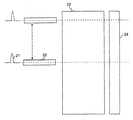
図2に、TIA/EIA−455−220試験法を概略的に表す。試験される多モードファイバのコア23は、パルス21を発光する850nmのレーザを用いて単一モードファイバ22によって半径方向に走査される。ファイバ・コアの他端での対応する出力パルスは、単一モードファイバの半径方向位置に関連するそれらの位置に基づいて高速光受信機によって全体的に記録される。これにより様々な半径方向のオフセットで選択的に励起されるモード群の間のモード遅延差に基づいて正確な情報を与える。次いで、DMD走査は、多重走査に基づいて評価される。
FIG. 2 schematically represents the TIA / EIA-455-220 test method. The
DMD走査データを図3a、図3b、図4aおよび図4bに示す。 DMD scan data is shown in FIGS. 3a, 3b, 4a and 4b.
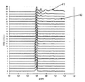
図3aおよび図3bは、曲がっていない状態に比較してきつく曲げられたときに、他の多モードファイバの設計におけるモード構造がどのように変化するのかを示す。 FIGS. 3a and 3b show how the mode structure in other multimode fiber designs changes when tightly bent compared to the unbent state.
図3aは、TIA/EIA−455−220規格によって定められるように、曲がっていない状態の多モード光ファイバ(MMF)のモード構造を示すDMDパルスの記録を示す。(31で示す)半径方向位置21ミクロンと(32で示す)半径方向位置24ミクロンの間の外側モード・ストラクチャに注目されたい。これらの位置で多重パルスが現れ始めることが理解できよう。 FIG. 3a shows a DMD pulse recording showing the mode structure of an unbent multimode optical fiber (MMF) as defined by the TIA / EIA-455-220 standard. Note the outer mode structure between a radial location of 21 microns (shown at 31) and a radial location of 24 microns (shown at 32). It can be seen that multiple pulses begin to appear at these positions.
図3bは、(本明細書できつく曲げられた状態として定められる)直径12.8mmのマンドレルの周りに曲げられることを除いて図3aに示すのと同じMMFのモード構造を示すDMDパルスの記録である。ここで、(31’で示す)半径方向位置21ミクロンと(32’で示す)半径方向位置24ミクロンの間の外側モード・ストラクチャは、図3aの曲がっていない状態と曲げられた状態の間でかなりの変化を受けている。とりわけ、図3b中の21ミクロンと24ミクロンの間に示すパルスは、有意に減らされており、したがって信号パワーの実質的な損失を示している。
FIG. 3b shows a DMD pulse recording showing the same MMF mode structure as shown in FIG. 3a except that it is bent around a 12.8 mm diameter mandrel (defined as tightly bent in this specification). It is. Here, the outer mode structure between the
図3aと図3bの比較では、0〜23の半径について計算された外側モード・ストラクチャおよびDMDの値が劇的に変化していることは明らかである。加えて、(19ミクロン以上における)外側モードにおいて進むパワーは、有意に低下しており、モード・エネルギが再配分されたこと、およびより多くのパワーがクラッド・モードの中に漏れていることを示唆している。モード・エネルギのこの再配分は、2つの効果を有する。1つは、よく知られているように、かなり曲げられたときにファイバ損失が増大することである。しかし、本発明の前には、曲げられた状態に関連するモード構造への影響は、観察されていない。 In the comparison of FIGS. 3a and 3b, it is clear that the outer mode structure and DMD values calculated for radii from 0 to 23 have changed dramatically. In addition, the power traveling in the outer mode (above 19 microns) has been significantly reduced, indicating that mode energy has been redistributed and more power is leaking into the cladding mode. Suggests. This redistribution of mode energy has two effects. One is, as is well known, that fiber loss increases when bent significantly. However, prior to the present invention, no effect on the mode structure associated with the bent state has been observed.
ビット誤り率(BER)システム検査では、他のMMF設計および規格ファイバにおけるモード帯域幅および追加の損失は、きつい曲げの下で測定されるとき、リンクを絶えさせる(>10−12BER)かなりの不利益をもたらすことが示されている。本発明によって作製されたファイバであれば、BERシステム検査における不利益は、他のMMFおよび規格ファイバを用いてなされる試験に比較して大いに最小にされ、リンクは、10−12BERより良い状態で動作することが示されている。 In bit error rate (BER) system inspection, mode bandwidth and additional loss in other MMF designs and standard fibers can cause the link to extinguish (> 10 −12 BER) when measured under tight bends. Has been shown to be detrimental. For fibers made in accordance with the present invention, the disadvantages in BER system testing are greatly minimized compared to tests done using other MMF and standard fibers, and the link is in a better state than 10-12 BER. Has been shown to work.
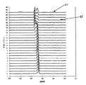
図4aおよび図4bは、本発明による多モードファイバの設計についてのモード構造が、曲がっていない状態に比較してきつく曲げられたときに変化しないことを示す。 4a and 4b show that the mode structure for the multimode fiber design according to the present invention does not change when tightly bent compared to the unbent state.
図4aは、本発明の実施形態によって作製されたMMFのモード構造を示すDMDパルスの記録を示す。曲がっていない状態におけるMMFのパルスの記録を図4aに示す。(41で示す)半径方向位置21ミクロンと(42で示す)半径方向位置24ミクロンの間の外側モード・ストラクチャに注目されたい。図3aに示すDMDパルスの記録と同様に、パルスは、外側モード・ストラクチャに現れ始める。 FIG. 4a shows a DMD pulse recording showing the mode structure of an MMF made according to an embodiment of the present invention. The recording of the MMF pulse in the unbent state is shown in FIG. 4a. Note the outer mode structure between a radial location of 21 microns (shown at 41) and a radial location of 24 microns (shown at 42). Similar to the recording of the DMD pulse shown in FIG. 3a, the pulse begins to appear in the outer mode structure.
図4bは、直径12.8mmのマンドレルの周りに曲げられること(きつく曲げられた状態)を除いて図4aに示したのと同じMMFのモード構造を示す対応するDMDパルスの記録を示す。(41’で示す)半径方向位置21ミクロンと(42’で示す)半径方向位置24ミクロンの間の外側モード・ストラクチャは、曲がっていない状態と曲げられた状態の間で変わらないままであることに注目されたい。したがって、曲げられた状態で最小のMMFのパワー損失が図4aおよび図4bに示されるだけでなく、元のモード構造は、本質的に変わらず、元のままに留まる。
FIG. 4b shows a corresponding DMD pulse recording showing the same MMF mode structure as shown in FIG. 4a except that it is bent around a 12.8 mm diameter mandrel (tightly bent state). The outer mode structure between
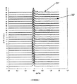
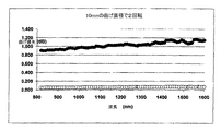
モード構造を保持したときの、MMFファイバ(上方の曲線)対規格ファイバ(下方の曲線)についての測定された追加のパワー損失の比較を図5に示す。この測定は、直径10mmのマンドレルの周りに2回転させた各ファイバの曲げ損失に関するものである。 A comparison of the measured additional power loss for the MMF fiber (upper curve) vs. the standard fiber (lower curve) when retaining the mode structure is shown in FIG. This measurement relates to the bending loss of each fiber rotated twice around a 10 mm diameter mandrel.
低曲げ損失に加えて高帯域幅の保持により、本発明の改善された多モード光ファイバは、短いジャンパに限定される必要がないことが明らかなはずである。この光ファイバは、例えば、1Gb/秒で2kmまで、10Gb/秒で550mまで、および40Gb/秒または100Gb/秒で推定100mまでの高伝達リンクにおける適用を可能にする。 It should be apparent that due to the retention of high bandwidth in addition to low bending loss, the improved multimode optical fiber of the present invention need not be limited to short jumpers. This optical fiber enables applications in high transmission links, for example up to 2 km at 1 Gb / s, up to 550 m at 10 Gb / s, and up to 100 m at 40 Gb / s or 100 Gb / s.
表1は、図1に示す屈折率プロファイルに関連する推奨されるパラメータを与える。これらのパラメータについて与えられる範囲内で、高帯域幅および超低曲げ損失を有する多モード光ファイバが同時に達成され得る。 Table 1 gives the recommended parameters associated with the refractive index profile shown in FIG. Within the range given for these parameters, multimode optical fibers with high bandwidth and very low bending loss can be achieved simultaneously.
前述の通り、これらのパラメータのうちの1つ、(式(a3−a2)/a1によってコア半径に正規化された際の表1で表現される)トレンチ幅は、光ファイバの曲げモードの保持を決定する際に特に重要であると分かった。例えば、表1中の範囲のうちコア半径(28.5ミクロン)についての範囲の中点を選択すると、パラメータ(a3−a2)/a1についての最小値が0.3であるとき、対応するトレンチ幅は、8.55ミクロンである。光ファイバの断面におけるトレンチの面積として表すと、この面積は1913μm2である。 As mentioned above, one of these parameters, the trench width (expressed in Table 1 when normalized to the core radius by the formula (a 3 −a 2 ) / a 1 ) is the bending of the optical fiber. It has been found to be particularly important in determining mode retention. For example, if the midpoint of the range for the core radius (28.5 microns) is selected from the range in Table 1, the minimum value for the parameter (a 3 −a 2 ) / a 1 is 0.3. The corresponding trench width is 8.55 microns. Expressed as the area of the trench in the cross section of the optical fiber, this area is 1913 μm 2 .
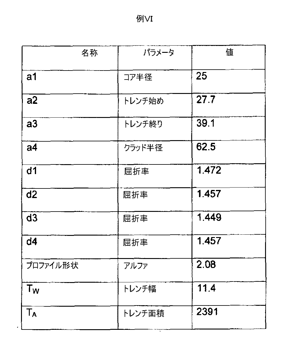
以下の具体例は、優れたBMPを示した光ファイバについてのパラメータを与える。寸法は、マイクロメートルの単位であり、面積は、平方マイクロメートルの単位である。 The following example gives the parameters for an optical fiber that showed excellent BMP. The dimensions are in units of micrometers and the area is in units of square micrometers.
これらの表で与えられる値は、正確な値である。しかし、小さな偏差、例えば+/−2%は、以下に示すものに匹敵する性能結果をやはり与えることになることが当業者によって理解されよう。 The values given in these tables are exact values. However, it will be appreciated by those skilled in the art that small deviations, eg +/− 2%, will still give performance results comparable to those shown below.
これらの光ファイバの設計の有効性を示すために、BMPが、上記の例ごとに測定され、以下の表、表IIに与えられる。単位は、ピコ秒毎メートルである。 To show the effectiveness of these optical fiber designs, BMP was measured for each of the above examples and is given in the following table, Table II. The unit is picoseconds per meter.
これらの設計パラメータのうちの2つのパラメータが際立っている。1つは、コア半径である。最適モード保持性能を示す光ファイバは、22〜28ミクロンの範囲内のコア半径を有したが、コア半径が7〜50ミクロンの範囲内である適切に設計されたMMFも、モード構造の完全性を示すことになることが分かった。トレンチの特性も、BMPの設計において重要なパラメータと考えられる。トレンチ幅TWは、少なくとも2.5ミクロンとすべきであり、好ましくは10〜13ミクロンとすべきである。 Two of these design parameters stand out. One is the core radius. An optical fiber that exhibits optimal mode retention performance had a core radius in the range of 22-28 microns, but a properly designed MMF with a core radius in the range of 7-50 microns also has mode structural integrity. It turns out that it will show. Trench characteristics are also considered an important parameter in BMP design. Trench width T W should be at least 2.5 microns, should be preferably between 10 to 13 microns.
トレンチ面積TAに関して表現すると、1500〜3500ミクロン2の範囲が推奨され、好ましくはこの範囲は、2000〜2900ミクロン2である。 When expressed in terms of trench area T A, is recommended a range of 1500 to 3500 microns 2, preferably the range is from 2000 to 2900 microns 2.
優れたBMPを示す光ファイバを設計できるこの狭い範囲の発見は、極めて予期せぬものである。この普通でない振舞いを示す光ファイバを生産するという設計目標はそれ自体、光ファイバ技術において新規であると考えられる。上記の8つの例のBMPを示す前には、このBMPを有する光ファイバがあり得ることを当技術分野で示すものは存在しなかった。表IIの中で与えられるデータは、BMPについての目標性能指数を示唆する。これらの例の大部分は、曲げられた状態と曲がっていない状態の間で0〜23μmのDMDの値の絶対変化量が0〜0.069ピコ秒毎メートルの範囲内である。この測定した性能データに基づいて、目標性能指数は、絶対値0.07ピコ秒毎メートル未満であり、好ましくは0.02ピコ秒毎メートル未満である。 This narrow range of discoveries in which optical fibers that exhibit excellent BMP can be designed is highly unexpected. The design goal of producing optical fibers that exhibit this unusual behavior is itself considered novel in optical fiber technology. Prior to presenting the eight example BMPs above, there was no indication in the art that there could be an optical fiber with this BMP. The data given in Table II suggests a target figure of merit for BMP. Most of these examples have an absolute change in the value of DMD of 0-23 μm between the bent and unbent states in the range of 0-0.069 picoseconds per meter. Based on this measured performance data, the target performance index is an absolute value of less than 0.07 picoseconds per meter, and preferably less than 0.02 picoseconds per meter.
トレンチ面積TAに関して表現すると、500〜3500μm2の範囲が推奨され、好ましくはこの範囲は、2000〜2900μm2である。 When expressed in terms of trench area T A, it is recommended range 500~3500Myuemu 2, preferably the range is 2000~2900μm 2.
本研究におけるコアのデルタnは、0.0125〜0.016である。トレンチ深さ(屈折率深さ)は、幅ほど極めて重要なパラメータではないと思われ、すなわち、より大きい変化量が有用であると思われる。0.0025〜0.012の値による内側クラッド(d2)より低いトレンチ深さ(屈折率差)が推奨され、好ましいトレンチ深さは、内側クラッド(d2)より低い0.003〜0.008である。この差は、次に隣接する内側クラッドから測定される。本明細書で表現される屈折率差は、シリカの屈折率(1.46)に基づく屈折率差に言及している。 The delta n of the core in this study is 0.0125 to 0.016. The trench depth (refractive index depth) does not seem to be as critical a parameter as the width, i.e., a larger amount of variation seems useful. Inner cladding by value of 0.0025-0.012 (d 2) from the lower trench depth (index difference) is recommended, preferably the trench depth is less than the inner cladding (d 2) .003-0. 008. This difference is then measured from the adjacent inner cladding. The refractive index difference expressed herein refers to a refractive index difference based on the refractive index of silica (1.46).
上記の光ファイバは、様々な知られた光ファイバ製造技術、例えば、外付け蒸着(OVD)、化学蒸着(CVD)、改良化学蒸着(MCVD)、気相軸蒸着(VAD)、プラズマ強化CVD(PCVD)などのいずれかを用いて製造できる。 The above optical fibers can be used in various known optical fiber manufacturing techniques such as external vapor deposition (OVD), chemical vapor deposition (CVD), modified chemical vapor deposition (MCVD), vapor phase axial deposition (VAD), plasma enhanced CVD ( PCVD) or the like can be used.
当業者は、本発明の様々な追加の変形形態を想到するであろう。技術を進歩させてきた原理およびそれらの均等物に基本的に依拠する本明細書の具体的な教示から逸脱したもの全ては、当然のことながら記載および主張した本発明の範囲内と考えられる。 Those skilled in the art will envision various additional variations of the invention. Any departure from the specific teachings of this specification that relies fundamentally on principles of advancement in technology and their equivalents will, of course, be considered within the scope of the invention as described and claimed.
Claims (22)
a1が、7〜50ミクロンであり、
アルファが、1.6〜2.2であり、
(a2−a1)/a1が、0.1〜0.7であり、
(a3−a2)/a1が、0.3〜0.6であり、
a4が、30〜250ミクロンであり、
d1−d4が、−0.019〜0.032であり、
d2−d4が、−0.01〜0.01であり、
d3−d4が、−0.05〜−0.0025であり、
d4が、1.4〜1.511である、多モード光ファイバ。 A core region having a first radius a 1 and a profile alpha, an inner cladding extending radially from a 1 to second radius a 2, the second radius a 2 to a third radius a 3 a trench extending radially, a multi-mode optical fiber and an outer cladding extending to a fourth radius a 4, the maximum refractive index of the core region is d 1, a refractive of the inner cladding rate is d 2, a refractive index of the trench is d 3, the refractive index of the outer cladding is d 4,
a 1 is 7 to 50 microns,
Alpha is 1.6 to 2.2,
(A 2 −a 1 ) / a 1 is 0.1 to 0.7,
(A 3 −a 2 ) / a 1 is 0.3 to 0.6,
a 4 is a 30 to 250 micron,
d 1 -d 4 is -0.019 to 0.032;
d 2 -d 4 is a -0.01~0.01,
d 3 -d 4 is -0.05 to -0.0025,
d 4 is a multimode optical fiber having a value of 1.4 to 1.511.
アルファが、1.96〜2.2であり、
(a2−a1)/a1が、0.1〜0.3であり、
(a3−a2)/a1が、0.3〜0.5であり、
a4が、62.5+/−20ミクロンであり、
d1−d4が、0.0037〜0.0237であり、
d2−d4が、−0.005〜0.005であり、
d3−d4が、−0.019〜−0.003であり、
d4が、1.43〜1.49である、請求項1に記載の光ファイバ。 a 1 is 21 to 29 microns,
Alpha is 1.96-2.2;
(A 2 −a 1 ) / a 1 is 0.1 to 0.3,
(A 3 -a 2) / a 1 is a 0.3 to 0.5,
a 4 is 62.5 +/− 20 microns,
d 1 -d 4 is a 0.0037 to 0.0237,
d 2 -d 4 is a -0.005~0.005,
d 3 -d 4 is -0.019 to -0.003,
The optical fiber according to claim 1, wherein d 4 is 1.43 to 1.49.
a1が22〜29マイクロメートルであり、そして、
a3−a2が少なくとも2.5ミクロンである、請求項3に記載の光ファイバ。 A core having a first radius a1, a trench extending radially from a second radius a2 to a third radius a3, and an outer cladding,
a 1 is 22-29 micrometers and
a 3 -a 2 is at least 2.5 microns, an optical fiber according to claim 3.
a2が、28.85+/−2%であり、
a3が、38.9+/−2%であり、
a4が、62.5+/−2%であり、
d1が、1.472+/−2%であり、
d2が、1.457+/−2%であり、
d3が、1.449+/−2%であり、
d4が、1.457+/−2%であり、
アルファが、2.08+/−2%である、請求項1に記載の光ファイバ。 a 1 is 26.12 microns +/- 2%;
a 2 is 28.85 +/− 2%,
a 3 is 38.9 +/- 2%;
a 4 is 62.5 +/− 2%,
d 1 is 1.472 +/- 2%;
d 2 is 1.457 +/- 2%;
d 3 is 1.449 +/- 2%;
d 4 is a 1.457 +/- 2%,
The optical fiber of claim 1, wherein alpha is 2.08 +/− 2%.
a1が、28.4ミクロン+/−2%であり、
a2が、28.81+/−2%であり、
a3が、40.71+/−2%であり、
a4が、62.5+/−2%であり、
d1が、1.472+/−2%であり、
d2が、1.457+/−2%であり、
d3が、1.449+/−2%であり、
d4が、1.457+/−2%であり、
アルファが、2.08+/−2%である、請求項3に記載の光ファイバ。 A core region having a first radius a 1 and a profile alpha, an inner cladding extending radially from a 1 to second radius a 2, the second radius a 2 to a third radius a 3 a trench extending radially, and an outer cladding extending to a fourth radius a 4, the maximum refractive index of the core region is d 1, the refractive index of the inner cladding is d 2, The trench has a refractive index of d 3 and the outer cladding has a refractive index of d 4 ;
a 1 is 28.4 microns +/- 2%;
a 2 is 28.81 +/− 2%,
a 3 is 40.71 +/- 2%;
a 4 is 62.5 +/− 2%,
d 1 is 1.472 +/- 2%;
d 2 is 1.457 +/- 2%;
d 3 is 1.449 +/- 2%;
d 4 is a 1.457 +/- 2%,
The optical fiber of claim 3, wherein alpha is 2.08 +/- 2%.
a2が、28+/−2%であり、
a3が、40.72+/−2%であり、
a4が、62.5+/−2%であり、
d1が、1.470+/−2%であり、
d2が、1.457+/−2%であり、
d3が、1.449+/−2%であり、
d4が、1.457+/−2%であり、
アルファが、2.08+/−2%である、請求項1に記載の光ファイバ。 a 1 is 24.4 microns +/- 2%;
a 2 is 28 +/- 2%,
a 3 is 40.72 +/- 2%;
a 4 is 62.5 +/− 2%,
d 1 is 1.470 +/- 2%;
d 2 is 1.457 +/- 2%;
d 3 is 1.449 +/- 2%;
d 4 is a 1.457 +/- 2%,
The optical fiber of claim 1, wherein alpha is 2.08 +/− 2%.
a1が、25ミクロン+/−2%であり、
a2が、25.5+/−2%であり、
a3が、36.9+/−2%であり、
a4が、62.5+/−2%であり、
d1が、1.472+/−2%であり、
d2が、1.457+/−2%であり、
d3が、1.449+/−2%であり、
d4が、1.457+/−2%であり、
アルファが、2.08+/−2%である、請求項3に記載の光ファイバ。 A core region having a first radius a 1 and a profile alpha, an inner cladding extending radially from a 1 to second radius a 2, the second radius a 2 to a third radius a 3 A radially extending trench and an outer cladding extending to a fourth radius a 4 , wherein the core region has a maximum refractive index d 1 and the inner cladding has a refractive index d 2 ; The trench has a refractive index of d 3 and the outer cladding has a refractive index of d 4 ;
a 1 is 25 microns +/- 2%;
a 2 is 25.5 +/− 2%,
a 3 is 36.9 +/- 2%;
a 4 is 62.5 +/− 2%,
d 1 is 1.472 +/- 2%;
d 2 is 1.457 +/- 2%;
d 3 is 1.449 +/- 2%;
d 4 is a 1.457 +/- 2%,
The optical fiber of claim 3, wherein alpha is 2.08 +/- 2%.
a2が、29.4+/−2%であり、
a3が、40.75+/−2%であり、
a4が、62.5+/−2%であり、
d1が、1.472+/−2%であり、
d2が、1.457+/−2%であり、
d3が、1.449+/−2%であり、
d4が、1.457+/−2%であり、
アルファが、2.08+/−2%である、請求項1に記載の光ファイバ。 a 1 is 25 microns +/- 2%;
a 2 is 29.4 +/− 2%,
a 3 is 40.75 +/− 2%,
a 4 is 62.5 +/− 2%,
d 1 is 1.472 +/- 2%;
d 2 is 1.457 +/- 2%;
d 3 is 1.449 +/- 2%;
d 4 is a 1.457 +/- 2%,
The optical fiber of claim 1, wherein alpha is 2.08 +/− 2%.
a2が、27.7+/−2%であり、
a3が、39.1+/−2%であり、
a4が、62.5+/−2%であり、
d1が、1.472+/−2%であり、
d2が、1.457+/−2%であり、
d3が、1.449+/−2%であり、
d4が、1.457+/−2%であり、
アルファが2.08+/−2%である、請求項1に記載の光ファイバ。 a 1 is 25 microns +/- 2%;
a 2 is 27.7 +/− 2%,
a 3 is 39.1 +/− 2%,
a 4 is 62.5 +/− 2%,
d 1 is 1.472 +/- 2%;
d 2 is 1.457 +/- 2%;
d 3 is 1.449 +/- 2%;
d 4 is a 1.457 +/- 2%,
The optical fiber of claim 1, wherein alpha is 2.08 +/− 2%.
a2が、30+/−2%であり、
a3が、40+/−2%であり、
a4が、62.5+/−2%であり、
d1が、1.472+/−2%であり、
d2が、1.457+/−2%であり、
d3が、1.446+/−2%であり、
d4が、1.457+/−2%であり、
アルファが、2.08+/−2%である、請求項1に記載の光ファイバ。 a 1 is 25 microns +/- 2%;
a 2 is 30 +/- 2%,
a 3 is 40 +/− 2%,
a 4 is 62.5 +/− 2%,
d 1 is 1.472 +/- 2%;
d 2 is 1.457 +/- 2%;
d 3 is 1.446 +/− 2%,
d 4 is a 1.457 +/- 2%,
The optical fiber of claim 1, wherein alpha is 2.08 +/− 2%.
a2が、28+/−2%であり、
a3が、38.23+/−2%であり、
a4が、62.5+/−2%であり、
d1が、1.470+/−2%であり、
d2が、1.457+/−2%であり、
d3が、1.449+/−2%であり、
d4が、1.457+/−2%であり、
アルファが、2.08+/−2%である、請求項1に記載の光ファイバ。 a 1 is 23.5 microns +/- 2%;
a 2 is 28 +/- 2%,
a 3 is 38.23 +/- 2%;
a 4 is 62.5 +/− 2%,
d 1 is 1.470 +/- 2%;
d 2 is 1.457 +/- 2%;
d 3 is 1.449 +/- 2%;
d 4 is a 1.457 +/- 2%,
The optical fiber of claim 1, wherein alpha is 2.08 +/− 2%.
a1が、25ミクロン+/−2%であり、
a2が、34+/−2%であり、
a3が、37.6+/−2%であり、
a4が、62.5+/−2%であり、
d1が、1.472+/−2%であり、
d2が、1.457+/−2%であり、
d3が、1.451+/−2%である、請求項3に記載の光ファイバ。 A core region having a first radius a 1 and a profile alpha, an inner cladding extending radially from a 1 to second radius a 2, the second radius a 2 to a third radius a 3 A radially extending trench and an outer cladding extending to a fourth radius a 4 , wherein the core region has a maximum refractive index d 1 and the inner cladding has a refractive index d 2 ; The trench has a refractive index of d 3 and the outer cladding has a refractive index of d 4 ;
a 1 is 25 microns +/- 2%;
a 2 is 34 +/- 2%,
a 3 is 37.6 +/− 2%,
a 4 is 62.5 +/− 2%,
d 1 is 1.472 +/- 2%;
d 2 is 1.457 +/- 2%;
The optical fiber according to claim 3 , wherein d 3 is 1.451 +/− 2%.
Applications Claiming Priority (4)
| Application Number | Priority Date | Filing Date | Title |
|---|---|---|---|
| US9763908P | 2008-09-17 | 2008-09-17 | |
| US61/097,639 | 2008-09-17 | ||
| US12/583,212 | 2009-08-17 | ||
| US12/583,212 US8520994B2 (en) | 2008-09-17 | 2009-08-17 | Bandwidth-maintaining multimode optical fibers |
Publications (2)
| Publication Number | Publication Date |
|---|---|
| JP2010072647A true JP2010072647A (en) | 2010-04-02 |
| JP5570166B2 JP5570166B2 (en) | 2014-08-13 |
Family
ID=41404305
Family Applications (1)
| Application Number | Title | Priority Date | Filing Date |
|---|---|---|---|
| JP2009215259A Active JP5570166B2 (en) | 2008-09-17 | 2009-09-17 | Bandwidth-maintaining multimode optical fiber |
Country Status (4)
| Country | Link |
|---|---|
| US (2) | US8520994B2 (en) |
| EP (1) | EP2166386B1 (en) |
| JP (1) | JP5570166B2 (en) |
| CN (2) | CN101738683B (en) |
Cited By (1)
| Publication number | Priority date | Publication date | Assignee | Title |
|---|---|---|---|---|
| JP2014052632A (en) * | 2012-09-05 | 2014-03-20 | Ofs Fitel Llc | Multiple lp mode fiber designed for mode division multiplex transmission |
Families Citing this family (48)
| Publication number | Priority date | Publication date | Assignee | Title |
|---|---|---|---|---|
| NL1024015C2 (en) * | 2003-07-28 | 2005-02-01 | Draka Fibre Technology Bv | Multimode optical fiber provided with a refractive index profile, optical communication system using this and method for manufacturing such a fiber. |
| US20070003198A1 (en) * | 2005-06-29 | 2007-01-04 | Lance Gibson | Low loss optical fiber designs and methods for their manufacture |
| FR2893149B1 (en) * | 2005-11-10 | 2008-01-11 | Draka Comteq France | OPTICAL FIBER MONOMODE. |
| FR2922657B1 (en) * | 2007-10-23 | 2010-02-12 | Draka Comteq France | MULTIMODE FIBER. |
| FR2932932B1 (en) * | 2008-06-23 | 2010-08-13 | Draka Comteq France Sa | MULTIPLEX WAVE LENGTH OPTIC SYSTEM WITH MULTIMODE OPTIC FIBERS |
| FR2933779B1 (en) | 2008-07-08 | 2010-08-27 | Draka Comteq France | MULTIMODE OPTIC FIBERS |
| FR2940839B1 (en) | 2009-01-08 | 2012-09-14 | Draka Comteq France | INDEX GRADIENT MULTIMODAL OPTICAL FIBER, METHODS FOR CHARACTERIZATION AND MANUFACTURE OF SUCH A FIBER |
| FR2946436B1 (en) | 2009-06-05 | 2011-12-09 | Draka Comteq France | MULTIMODE OPTICAL FIBER WITH LARGE BANDWIDTH WITH AN OPTIMIZED HEAT-SLEEVE INTERFACE |
| FR2953605B1 (en) | 2009-12-03 | 2011-12-16 | Draka Comteq France | MULTIMODE OPTICAL FIBER WITH BROAD BANDWIDTH AND LOW BENDBACK LOSSES |
| FR2953606B1 (en) | 2009-12-03 | 2012-04-27 | Draka Comteq France | MULTIMODE OPTICAL FIBER WITH BROAD BANDWIDTH AND LOW BENDBACK LOSSES |
| FR2953029B1 (en) | 2009-11-25 | 2011-11-18 | Draka Comteq France | MULTIMODE OPTICAL FIBER WITH LARGE BANDWIDTH WITH AN OPTIMIZED HEAT-SLEEVE INTERFACE |
| FR2949870B1 (en) * | 2009-09-09 | 2011-12-16 | Draka Compteq France | MULTIMODE OPTICAL FIBER HAVING IMPROVED BENDING LOSSES |
| FR2957153B1 (en) | 2010-03-02 | 2012-08-10 | Draka Comteq France | MULTIMODE OPTICAL FIBER WITH BROAD BANDWIDTH AND LOW BENDBACK LOSSES |
| US9014525B2 (en) | 2009-09-09 | 2015-04-21 | Draka Comteq, B.V. | Trench-assisted multimode optical fiber |
| FR2953030B1 (en) | 2009-11-25 | 2011-11-18 | Draka Comteq France | MULTIMODE OPTICAL FIBER WITH LARGE BANDWIDTH WITH AN OPTIMIZED HEAT-SLEEVE INTERFACE |
| FR2950156B1 (en) | 2009-09-17 | 2011-11-18 | Draka Comteq France | MULTIMODE OPTIC FIBER |
| WO2011100333A1 (en) | 2010-02-09 | 2011-08-18 | Ofs Fitel, Llc | Improvement of dmd performance in bend optimized multimode fiber |
| FR2966256B1 (en) | 2010-10-18 | 2012-11-16 | Draka Comteq France | MULTIMODE OPTICAL FIBER INSENSITIVE TO LOSSES BY |
| DE102011014915B4 (en) | 2010-10-19 | 2019-01-17 | J-Fiber Gmbh | Process for the production of an optical waveguide with an optimizable macrobending loss and preform for the production of an optical waveguide |
| DE102011009242B4 (en) | 2010-11-04 | 2020-09-03 | J-Plasma Gmbh | Optical fiber and semi-finished product for the production of an optical fiber with optimized properties |
| DE202010017188U1 (en) | 2010-11-04 | 2011-04-21 | J-Plasma Gmbh | Optical waveguide and semifinished product for producing an optical waveguide with bending-optimized properties |
| EP2482106B1 (en) | 2011-01-31 | 2014-06-04 | Draka Comteq B.V. | Multimode fiber |
| FR2971061B1 (en) | 2011-01-31 | 2013-02-08 | Draka Comteq France | BROAD BANDWIDTH OPTICAL FIBER WITH LOW CURB LOSSES |
| EP2503368A1 (en) | 2011-03-24 | 2012-09-26 | Draka Comteq B.V. | Multimode optical fiber with improved bend resistance |
| EP2506044A1 (en) | 2011-03-29 | 2012-10-03 | Draka Comteq B.V. | Multimode optical fiber |
| EP2518546B1 (en) | 2011-04-27 | 2018-06-20 | Draka Comteq B.V. | High-bandwidth, radiation-resistant multimode optical fiber |
| DE102011109838A1 (en) * | 2011-05-27 | 2012-11-29 | J-Plasma Gmbh | optical fiber |
| CN102193142B (en) | 2011-06-28 | 2013-06-26 | 长飞光纤光缆有限公司 | Bending-resistant large core high numerical aperture multimode fiber |
| DK2541292T3 (en) | 2011-07-01 | 2014-12-01 | Draka Comteq Bv | A multimode optical fiber |
| DE102011052197B4 (en) | 2011-07-27 | 2019-08-01 | J-Plasma Gmbh | Fiber optic cables with bending-optimized properties |
| US8768129B2 (en) * | 2011-09-21 | 2014-07-01 | Ofs Fitel, Llc | Optimized ultra large area optical fibers |
| US8687932B2 (en) * | 2011-09-21 | 2014-04-01 | Ofs Fitel, Llc | Optimized ultra large area optical fibers |
| US8718431B2 (en) * | 2011-09-21 | 2014-05-06 | Ofs Fitel, Llc | Optimized ultra large area optical fibers |
| US8565566B2 (en) | 2011-10-05 | 2013-10-22 | Sumitomo Electric Industries, Ltd. | Multi-mode optical fiber |
| US8565567B2 (en) | 2011-11-23 | 2013-10-22 | Sumitomo Electric Industries, Ltd. | Multi-mode optical fiber |
| EP2642322B1 (en) * | 2012-03-23 | 2019-07-10 | Draka Comteq B.V. | Bend-resistant multimode optical fiber |
| US9671552B2 (en) * | 2012-09-05 | 2017-06-06 | Ofs Fitel, Llc | 9 LP-mode fiber designs for mode-division multiplexing |
| US9709731B2 (en) | 2012-09-05 | 2017-07-18 | Ofs Fitel, Llc | Multiple LP-mode fiber designs for mode-division multiplexing |
| WO2014206464A1 (en) | 2013-06-26 | 2014-12-31 | Draka Comteq Bv | Bend-insensitive multimode optical fiber with reduced impact of leaky modes |
| JP6664327B2 (en) | 2014-01-31 | 2020-03-13 | オーエフエス ファイテル,エルエルシー | Design and manufacture of multimode optical fiber |
| CN104834053A (en) * | 2014-02-08 | 2015-08-12 | 住友电气工业株式会社 | MMF and manufacturing method thereof |
| WO2015133407A1 (en) * | 2014-03-07 | 2015-09-11 | 株式会社フジクラ | Multi-core fiber |
| EP3215876B1 (en) * | 2014-11-07 | 2022-01-05 | Prysmian S.p.A. | Multimode optical fiber for power-over-fiber applications |
| CN105204111A (en) * | 2015-10-28 | 2015-12-30 | 长飞光纤光缆股份有限公司 | Multimode optical fiber with relatively low intermodal dispersion |
| CN105577299B (en) * | 2015-12-24 | 2018-07-27 | 中国电子科技集团公司第四十一研究所 | A kind of bandwidth for multimode optical fibers measuring device and method |
| CN108333671B (en) * | 2018-02-01 | 2019-12-03 | 烽火通信科技股份有限公司 | Anti-bending multimode fiber |
| CN108983350B (en) * | 2018-09-25 | 2020-09-22 | 长飞光纤光缆股份有限公司 | Small-core-diameter graded-index optical fiber |
| CN111366180B (en) * | 2020-05-08 | 2022-02-15 | 中天科技光纤有限公司 | External parameter measuring method based on optical fiber sensor |
Citations (1)
| Publication number | Priority date | Publication date | Assignee | Title |
|---|---|---|---|---|
| WO2008085851A1 (en) * | 2007-01-08 | 2008-07-17 | Corning Incorporated | Bend resistant multimode optical fiber |
Family Cites Families (15)
| Publication number | Priority date | Publication date | Assignee | Title |
|---|---|---|---|---|
| US4691990A (en) * | 1984-11-13 | 1987-09-08 | American Telephone And Telegraph Company, At&T Bell Laboratories | Optical fiber with depressed index outer cladding |
| US4852968A (en) * | 1986-08-08 | 1989-08-01 | American Telephone And Telegraph Company, At&T Bell Laboratories | Optical fiber comprising a refractive index trench |
| CN1682134A (en) | 2002-09-12 | 2005-10-12 | 旭硝子株式会社 | Plastic optical fiber |
| KR100526516B1 (en) * | 2003-07-11 | 2005-11-08 | 삼성전자주식회사 | Graded-index optical fiber for high bit-rate and local area network |
| US7043126B2 (en) | 2003-07-18 | 2006-05-09 | Fujikura Ltd. | Graded-index multimode fiber and manufacturing method therefor |
| FR2864254B1 (en) | 2003-12-23 | 2006-03-03 | Cit Alcatel | HOM MULTIMODE OPTICAL FIBER WITH DISPERSION MANAGEMENT |
| US7187833B2 (en) * | 2004-04-29 | 2007-03-06 | Corning Incorporated | Low attenuation large effective area optical fiber |
| WO2006010798A1 (en) * | 2004-07-26 | 2006-02-02 | Photonium Oy | Multimode optical fiber with low differential mode delay |
| WO2007043060A1 (en) | 2005-10-07 | 2007-04-19 | Sterlite Optical Technologies Ltd. | Optical fiber having higher bandwidth and method for producing the same |
| US7526169B2 (en) * | 2006-11-29 | 2009-04-28 | Corning Incorporated | Low bend loss quasi-single-mode optical fiber and optical fiber line |
| JP2010520496A (en) * | 2007-02-28 | 2010-06-10 | コーニング インコーポレイテッド | Wide effective area optical fiber |
| WO2008136918A2 (en) * | 2007-05-07 | 2008-11-13 | Corning Incorporated | Large effective area fiber |
| US20090169163A1 (en) * | 2007-12-13 | 2009-07-02 | Abbott Iii John Steele | Bend Resistant Multimode Optical Fiber |
| US7773848B2 (en) * | 2008-07-30 | 2010-08-10 | Corning Incorporated | Low bend loss single mode optical fiber |
| US7903918B1 (en) * | 2010-02-22 | 2011-03-08 | Corning Incorporated | Large numerical aperture bend resistant multimode optical fiber |
-
2009
- 2009-08-17 US US12/583,212 patent/US8520994B2/en active Active
- 2009-09-16 CN CN200910211614.3A patent/CN101738683B/en active Active
- 2009-09-16 EP EP09011817.5A patent/EP2166386B1/en active Active
- 2009-09-16 CN CN201310551704.3A patent/CN104020520B/en active Active
- 2009-09-17 JP JP2009215259A patent/JP5570166B2/en active Active
-
2013
- 2013-07-29 US US13/953,470 patent/US20140270670A1/en not_active Abandoned
Patent Citations (1)
| Publication number | Priority date | Publication date | Assignee | Title |
|---|---|---|---|---|
| WO2008085851A1 (en) * | 2007-01-08 | 2008-07-17 | Corning Incorporated | Bend resistant multimode optical fiber |
Cited By (2)
| Publication number | Priority date | Publication date | Assignee | Title |
|---|---|---|---|---|
| JP2014052632A (en) * | 2012-09-05 | 2014-03-20 | Ofs Fitel Llc | Multiple lp mode fiber designed for mode division multiplex transmission |
| JP2016128936A (en) * | 2012-09-05 | 2016-07-14 | オーエフエス ファイテル,エルエルシー | Multiple lp mode fiber designed for mode division multiplex transmission |
Also Published As
| Publication number | Publication date |
|---|---|
| EP2166386A1 (en) | 2010-03-24 |
| CN101738683B (en) | 2014-12-17 |
| US20100067858A1 (en) | 2010-03-18 |
| EP2166386B1 (en) | 2014-04-30 |
| CN104020520B (en) | 2017-01-04 |
| CN104020520A (en) | 2014-09-03 |
| JP5570166B2 (en) | 2014-08-13 |
| US20140270670A1 (en) | 2014-09-18 |
| US8520994B2 (en) | 2013-08-27 |
| CN101738683A (en) | 2010-06-16 |
Similar Documents
| Publication | Publication Date | Title |
|---|---|---|
| JP5570166B2 (en) | Bandwidth-maintaining multimode optical fiber | |
| US8009950B2 (en) | Multimode fiber | |
| EP2259105B1 (en) | Very broad bandwidth multimode optical fibre with an optimized core-cladding interface and reduced cladding effect | |
| JP6031276B2 (en) | Multimode optical fiber | |
| JP5945441B2 (en) | Multimode optical fiber | |
| JP5945447B2 (en) | High-bandwidth, radiation-resistant multimode optical fiber | |
| DK2299302T3 (en) | A multimode optical fiber with improved bending loss | |
| JP5468075B2 (en) | Multimode fiber having at least two claddings | |
| JP5606742B2 (en) | Single mode optical fiber | |
| KR101539555B1 (en) | Single mode optical fibre | |
| EP2339383B1 (en) | Multimode optical fiber with low bending losses and reduced cladding effect | |
| JP2011118392A (en) | High-bandwidth multimode optical fiber reduced in bending loss | |
| JP2012203416A (en) | Multimode optical fiber with improved bend resistance | |
| CN103380388A (en) | Bend-insensitive optical fiber having small coating diameter and optical cable comprising the same | |
| JP2010176123A (en) | Single-mode optical fiber having enlarged effective area | |
| JP2008257250A (en) | Transmission optical fiber having large effective area | |
| CN111007590B (en) | Weakly coupled few-mode optical fiber for mode division multiplexing and corresponding optical transmission system | |
| US9568669B2 (en) | Bandwidth-maintaining multimode optical fibers | |
| JP6918983B2 (en) | Multimode fiber optics optimized to operate around 1060 nm, and corresponding multimode optics |
Legal Events
| Date | Code | Title | Description |
|---|---|---|---|
| A621 | Written request for application examination |
Free format text: JAPANESE INTERMEDIATE CODE: A621 Effective date: 20100305 |
|
| A521 | Request for written amendment filed |
Free format text: JAPANESE INTERMEDIATE CODE: A523 Effective date: 20110303 |
|
| RD04 | Notification of resignation of power of attorney |
Free format text: JAPANESE INTERMEDIATE CODE: A7424 Effective date: 20120710 |
|
| A977 | Report on retrieval |
Free format text: JAPANESE INTERMEDIATE CODE: A971007 Effective date: 20120808 |
|
| A131 | Notification of reasons for refusal |
Free format text: JAPANESE INTERMEDIATE CODE: A131 Effective date: 20121011 |
|
| A601 | Written request for extension of time |
Free format text: JAPANESE INTERMEDIATE CODE: A601 Effective date: 20130111 |
|
| A602 | Written permission of extension of time |
Free format text: JAPANESE INTERMEDIATE CODE: A602 Effective date: 20130117 |
|
| A521 | Request for written amendment filed |
Free format text: JAPANESE INTERMEDIATE CODE: A523 Effective date: 20130411 |
|
| A131 | Notification of reasons for refusal |
Free format text: JAPANESE INTERMEDIATE CODE: A131 Effective date: 20130425 |
|
| A601 | Written request for extension of time |
Free format text: JAPANESE INTERMEDIATE CODE: A601 Effective date: 20130725 |
|
| A602 | Written permission of extension of time |
Free format text: JAPANESE INTERMEDIATE CODE: A602 Effective date: 20130730 |
|
| A131 | Notification of reasons for refusal |
Free format text: JAPANESE INTERMEDIATE CODE: A131 Effective date: 20131112 |
|
| A601 | Written request for extension of time |
Free format text: JAPANESE INTERMEDIATE CODE: A601 Effective date: 20140212 |
|
| A602 | Written permission of extension of time |
Free format text: JAPANESE INTERMEDIATE CODE: A602 Effective date: 20140217 |
|
| A521 | Request for written amendment filed |
Free format text: JAPANESE INTERMEDIATE CODE: A523 Effective date: 20140512 |
|
| TRDD | Decision of grant or rejection written | ||
| A01 | Written decision to grant a patent or to grant a registration (utility model) |
Free format text: JAPANESE INTERMEDIATE CODE: A01 Effective date: 20140527 |
|
| A61 | First payment of annual fees (during grant procedure) |
Free format text: JAPANESE INTERMEDIATE CODE: A61 Effective date: 20140624 |
|
| R150 | Certificate of patent or registration of utility model |
Ref document number: 5570166 Country of ref document: JP Free format text: JAPANESE INTERMEDIATE CODE: R150 |
|
| R250 | Receipt of annual fees |
Free format text: JAPANESE INTERMEDIATE CODE: R250 |
|
| R250 | Receipt of annual fees |
Free format text: JAPANESE INTERMEDIATE CODE: R250 |
|
| R250 | Receipt of annual fees |
Free format text: JAPANESE INTERMEDIATE CODE: R250 |
|
| R250 | Receipt of annual fees |
Free format text: JAPANESE INTERMEDIATE CODE: R250 |
|
| R250 | Receipt of annual fees |
Free format text: JAPANESE INTERMEDIATE CODE: R250 |
|
| R250 | Receipt of annual fees |
Free format text: JAPANESE INTERMEDIATE CODE: R250 |
|
| R250 | Receipt of annual fees |
Free format text: JAPANESE INTERMEDIATE CODE: R250 |