WO2012014884A1 - 防水コネクタ - Google Patents
防水コネクタ Download PDFInfo
- Publication number
- WO2012014884A1 WO2012014884A1 PCT/JP2011/066949 JP2011066949W WO2012014884A1 WO 2012014884 A1 WO2012014884 A1 WO 2012014884A1 JP 2011066949 W JP2011066949 W JP 2011066949W WO 2012014884 A1 WO2012014884 A1 WO 2012014884A1
- Authority
- WO
- WIPO (PCT)
- Prior art keywords
- connector
- flat cable
- cable
- connector housing
- holder
- Prior art date
- Legal status (The legal status is an assumption and is not a legal conclusion. Google has not performed a legal analysis and makes no representation as to the accuracy of the status listed.)
- Ceased
Links
Images





Classifications
-
- H—ELECTRICITY
- H01—ELECTRIC ELEMENTS
- H01R—ELECTRICALLY-CONDUCTIVE CONNECTIONS; STRUCTURAL ASSOCIATIONS OF A PLURALITY OF MUTUALLY-INSULATED ELECTRICAL CONNECTING ELEMENTS; COUPLING DEVICES; CURRENT COLLECTORS
- H01R12/00—Structural associations of a plurality of mutually-insulated electrical connecting elements, specially adapted for printed circuits, e.g. printed circuit boards [PCB], flat or ribbon cables, or like generally planar structures, e.g. terminal strips, terminal blocks; Coupling devices specially adapted for printed circuits, flat or ribbon cables, or like generally planar structures; Terminals specially adapted for contact with, or insertion into, printed circuits, flat or ribbon cables, or like generally planar structures
- H01R12/70—Coupling devices
- H01R12/77—Coupling devices for flexible printed circuits, flat or ribbon cables or like structures
-
- H—ELECTRICITY
- H01—ELECTRIC ELEMENTS
- H01R—ELECTRICALLY-CONDUCTIVE CONNECTIONS; STRUCTURAL ASSOCIATIONS OF A PLURALITY OF MUTUALLY-INSULATED ELECTRICAL CONNECTING ELEMENTS; COUPLING DEVICES; CURRENT COLLECTORS
- H01R13/00—Details of coupling devices of the kinds covered by groups H01R12/70 or H01R24/00 - H01R33/00
- H01R13/46—Bases; Cases
- H01R13/52—Dustproof, splashproof, drip-proof, waterproof, or flameproof cases
- H01R13/5219—Sealing means between coupling parts, e.g. interfacial seal
- H01R13/5221—Sealing means between coupling parts, e.g. interfacial seal having cable sealing means
-
- H—ELECTRICITY
- H01—ELECTRIC ELEMENTS
- H01R—ELECTRICALLY-CONDUCTIVE CONNECTIONS; STRUCTURAL ASSOCIATIONS OF A PLURALITY OF MUTUALLY-INSULATED ELECTRICAL CONNECTING ELEMENTS; COUPLING DEVICES; CURRENT COLLECTORS
- H01R13/00—Details of coupling devices of the kinds covered by groups H01R12/70 or H01R24/00 - H01R33/00
- H01R13/46—Bases; Cases
- H01R13/52—Dustproof, splashproof, drip-proof, waterproof, or flameproof cases
-
- H—ELECTRICITY
- H01—ELECTRIC ELEMENTS
- H01R—ELECTRICALLY-CONDUCTIVE CONNECTIONS; STRUCTURAL ASSOCIATIONS OF A PLURALITY OF MUTUALLY-INSULATED ELECTRICAL CONNECTING ELEMENTS; COUPLING DEVICES; CURRENT COLLECTORS
- H01R13/00—Details of coupling devices of the kinds covered by groups H01R12/70 or H01R24/00 - H01R33/00
- H01R13/46—Bases; Cases
- H01R13/52—Dustproof, splashproof, drip-proof, waterproof, or flameproof cases
- H01R13/5205—Sealing means between cable and housing, e.g. grommet
-
- H—ELECTRICITY
- H01—ELECTRIC ELEMENTS
- H01R—ELECTRICALLY-CONDUCTIVE CONNECTIONS; STRUCTURAL ASSOCIATIONS OF A PLURALITY OF MUTUALLY-INSULATED ELECTRICAL CONNECTING ELEMENTS; COUPLING DEVICES; CURRENT COLLECTORS
- H01R12/00—Structural associations of a plurality of mutually-insulated electrical connecting elements, specially adapted for printed circuits, e.g. printed circuit boards [PCB], flat or ribbon cables, or like generally planar structures, e.g. terminal strips, terminal blocks; Coupling devices specially adapted for printed circuits, flat or ribbon cables, or like generally planar structures; Terminals specially adapted for contact with, or insertion into, printed circuits, flat or ribbon cables, or like generally planar structures
- H01R12/70—Coupling devices
- H01R12/77—Coupling devices for flexible printed circuits, flat or ribbon cables or like structures
- H01R12/771—Details
- H01R12/774—Retainers
Definitions
- the present invention relates to a waterproof connector.
- a flexible flat cable as a flat cable having flexibility such as a flexible circuit board (FPC), an insulating housing as a connector into which the flexible flat cable is inserted, and this
- a seal member having a slit which is accommodated in a contact insertion opening of an insulating housing and through which a flexible flat cable can be inserted, and a seal member as a holder having a groove which is hinged to the vicinity of the contact insertion opening and through which the flexible flat cable can pass The thing provided with the press member is known (for example, refer patent document 1).
- the sealing member accommodated in the contact insertion opening is compressed by the sealing member pressing member, thereby ensuring the waterproofness between the flexible flat cable and the insulating housing.
- an object of the present invention is to provide a waterproof connector that can reliably hold a flat cable to a connector housing.
- a flat cable provided with a plurality of conductor portions, a connector housing provided with a rectangular insertion port for inserting the flat cable, the flat cable inserted, and the insertion port and the flat plate
- a sealing member that seals between the cable and a lock portion that covers an outer periphery of the opening end of the connector housing in which the insertion port is formed and engages with the opening end.
- a waterproof connector having a holder for holding the insertion port, wherein the holder is provided with a plurality of bosses which are inserted into a plurality of connector side through holes respectively provided on the upper and lower surfaces of the opening end.
- the flat cable is provided with a plurality of cable side through holes through which the plurality of bosses are inserted on the rear end side in the insertion direction of the seal member into the connector housing,
- a waterproof connector in which a rear end surface of the seal member is in contact with the plurality of bosses inserted through the plurality of cable side through holes.
- the plurality of bosses of the holder are inserted into the plurality of connector side through holes provided on the upper and lower surfaces of the opening end of the connector housing, respectively. Since the plurality of cable side through holes are inserted, the position in the width direction of the flat cable in the insertion port can be fixed.
- the rear end surface of the seal member through which the flat cable is inserted is in contact with a plurality of bosses that pass through the plurality of cable side through holes, so that the position of the flat cable in the length direction in the insertion port is fixed. can do.
- the flat cable can be prevented from rattling in the insertion port, and the flat cable can be reliably held with respect to the connector housing.
- FIG. 1 is a perspective view of a waterproof connector according to an embodiment of the present invention.
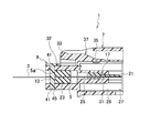
- FIG. 2 is a longitudinal sectional view of the waterproof connector according to the embodiment of the present invention.
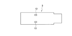
- FIG. 3 is a top view of the flat cable of the waterproof connector according to the embodiment of the present invention.
- FIG. 4A is an enlarged view when FPC or FFC is applied to the flat cable of the waterproof connector according to the embodiment of the present invention.
- FIG.4 (b) is an enlarged view when FPC is applied to the flat cable of the waterproof connector which concerns on embodiment of this invention.
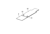
- FIG. 5 is a perspective view when a reinforcing plate is provided on the flat cable of the waterproof connector according to the embodiment of the present invention.
- FIG. 6 is a perspective view of the cable assembly of the waterproof connector according to the embodiment of the present invention.
- FIG. 7 is a perspective view of the connector housing of the waterproof connector according to the embodiment of the present invention.
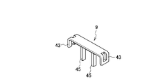
- FIG. 8 is a perspective view of the holder of the waterproof connector according to the embodiment of the present invention.
- FIG. 9 is a perspective view when the holder of the waterproof connector according to the embodiment of the present invention is assembled to the connector housing.
- FIG. 10 is an enlarged cross-sectional view of a main part of the waterproof connector according to the embodiment of the present invention.
- a waterproof connector according to an embodiment of the present invention will be described with reference to FIGS.
- the waterproof connector 1 includes a flat cable 3, a seal member 5, a connector housing 7, and a holder 9, as shown in FIGS.
- the flat cable 3 is formed of a flexible flat cable such as a flexible circuit board (FPC) or a flexible flat cable (FFC), and a plurality of conductor portions 11 are provided. It has been. A plurality (two in this case) of cable side through holes 13 through which the bosses 45 of the holder 9 are inserted are provided between the plurality of conductor portions 11.
- FPC flexible circuit board
- FFC flexible flat cable
- the cable side through hole 13 is located between the adjacent conductor portions 11 and is provided so as to penetrate the flat cable 3 in the thickness direction.
- a reinforcing plate 15 that covers the plurality of conductors 11 is integrally provided on the upper surface of the flat cable 3, and the reinforcing plate 15 is also provided with a through hole at a portion where the cable side through hole 13 is located. ing.
- the conductor portion 11 is affected by increasing the pitch between the plurality of conductor portions 11.
- the cable side through-hole 13 can be provided at an arbitrary place without giving.
- FPC is applied to the flat cable 3, as shown in FIG. 4B
- a plurality of conductor portions 11 can be freely routed, and the conductor portions 11 can be avoided by avoiding the cable side through holes 13. Therefore, the cable side through hole 13 can be provided at an arbitrary position without affecting the conductor portion 11.
- the cable assembly 19 is configured by assembling the slider 17 and the seal member 5 to such a flat cable 3.
- the slider 17 is made of a resin material and is made of a two-divided member that covers the upper surface and the lower surface of the flat cable 3.
- the slider 17 covers the lower surface side so that a part of the front end side of the conductor portion 11 of the flat cable 3 is exposed to the outside, and the upper surface member covers the front end side of the conductor portion 11 of the flat cable 3.
- It covers the whole, and the tip end side is a connecting portion 21 that is sandwiched and connected by a fork-shaped mating terminal (not shown).
- the connection portion 21 protrudes from the housing portion 25 in a state of being housed in the housing portion 25 of the connector housing 7 and is electrically connected to the mating terminal.
- Such a slider 17 can protect the connection portion 21 and can adjust the contact load with the mating terminal by changing the thickness of the slider 17 of the connection portion 21.
- the seal member 5 is made of an elastic material such as rubber, and is integrally formed with the flat cable 3 so that the flat cable 3 is inserted in close contact with the central portion.
- the outer periphery of the seal member 5 is elastically in close contact with the inner peripheral surface of the insertion port 23 in the insertion port 23 of the connector housing 7, and between the connector housing 7 and the flat cable 3. Seal.
- the seal member 5 is disposed adjacent to the front end side in the insertion direction of the flat cable 3 into the connector housing 7 with respect to the cable side through hole 13 of the flat cable 3. Therefore, as shown in FIG. 10, when the boss 45 of the holder 9 is inserted into the cable side through hole 13, the rear end surface 5 a of the seal member 5 is brought into contact with the boss 45, and the flat cable 3 is connected to the connector housing 7. Can be prevented from coming off.
- the cable assembly 19 in which the slider 17 and the seal member 5 are assembled to the flat cable 3 is inserted from the insertion port 23 of the connector housing 7 and assembled to the connector housing 7.
- the connector housing 7 is made of a resin material and includes an insertion port 23, a housing portion 25, a frontage 27, and a mating connector housing portion 29.
- the insertion port 23 is formed in a rectangular shape at an opening end 32 that opens toward one side of the connector housing 7.
- the cable assembly 19 is inserted from the insertion port 23, and the cable assembly 19 is assembled to the connector housing 7.
- the insertion member 23 accommodates the seal member 5 of the cable assembly 19 and seals between the connector housing 7 and the flat cable 3.
- the housing portion 25 is provided on the inner side of the connector housing 7 with respect to the insertion port 23, and is communicated with the insertion port 23 and formed in a cylindrical shape.
- a through hole 31 is provided at the bottom of the accommodating portion 25.
- the accommodating portion 25 accommodates the slider 17 of the cable assembly 19, and the connecting portion 21 of the slider 17 is inserted through the through hole 31 and protrudes into the mating connector accommodating portion 29.
- the base end side of the connecting portion 21 of the slider 17 is brought into contact with the bottom portion of the accommodating portion 25, and the cable assembly 19 is moved in the insertion direction into the connector housing 7. Can be regulated.
- the front opening 27 is opened toward the other side of the connector housing 7.
- a mating connector (not shown) that accommodates the mating terminal is inserted from the opening 27, and the mating connector is assembled to the connector housing 7.
- the frontage 27 communicates with a mating connector housing portion 29 that houses a mating connector.
- the mating connector housing part 29 is provided on the outer peripheral side of the housing part 25 inside the connector housing 7.
- the mating connector inserted from the frontage 27 is housed so as to cover the outer periphery of the housing portion 25.
- the mating connector housing portion 29 is provided with a lock portion 35 of a lock arm 37 that has an operation portion 33 and a lock portion 35 and is swingably provided. Fixed.
- the connector housing 7 configured in this manner is mounted on a board (not shown) such as a circuit board, and makes the flat cable 3 connected to an electronic component or the like and a mating terminal connected to the board conductive. Applies to In addition, beak portions 39 to be engaged with the lock portions 43 of the holder 9 are projected on both side surfaces of the outer periphery of the opening end portion 32 in which the insertion port 23 of the connector housing 7 is formed, and on the upper and lower surfaces. A plurality (two in this case) of connector-side through holes 41 through which the bosses 45 of the holder 9 are inserted are provided. The connector side through hole 41 is provided in the insertion port 23 so that the position of the connector side through hole 41 coincides with the cable side through hole 13 of the flat cable 3 when the flat cable 3 is assembled to the connector housing 7.
- the holder 9 is made of a resin material and is formed in a U shape so as to cover the upper surface side of the outer periphery of the open end 32 of the connector housing 7. Further, lock portions 43 that are engaged with the beak portions 39 of the connector housing 7 are respectively provided at both end portions of the U-shape of the holder 9, and the holder 9 is fixed to the connector housing 7. A plurality (two in this case) of bosses 45 project from the center portion of the holder 9 toward the insertion port 23 side (lower side) of the connector housing 7.
- the holder 9 is assembled from above the opening end 32 of the connector housing 7 so that the boss 45 passes through the connector side through hole 41.
- the boss 45 is flat when assembled to the connector housing 7 of the holder 9 shown in FIG.
- the cable side through hole 13 of the cable 3 and the connector side through hole 41 located below the insertion port 23 can be inserted.
- the lock portion 43 and the beak portion 39 are engaged, and the holder 9 is fixed to the connector housing 7.
- the boss 45 passes through the connector side through hole 41 and the cable side through hole 13, thereby restricting movement of the flat cable 3 in the width direction.
- the plurality of bosses 45 of the holder 9 are inserted into the plurality of connector side through holes 41 respectively provided on the upper and lower surfaces of the opening end portion 32 of the connector housing 7 in which the insertion port 23 is formed, Since the plurality of bosses 45 pass through the plurality of cable side through holes 13 of the flat cable 3, the position in the width direction of the flat cable 3 in the insertion port 23 can be fixed.
- the flat cable 3 can be prevented from rattling in the insertion port 23, and the flat cable 3 can be securely held to the connector housing 7.
- the boss of the holder is inserted from the upper surface side to the lower surface side of the opening end portion where the insertion port of the connector housing is formed. It is good also as a structure inserted through toward the upper surface side.
- the mating terminal is accommodated in the mating connector, but a configuration may be adopted in which a housing portion for accommodating the mating terminal is provided on the front side of the connector housing so that the mating terminal is accommodated in the connector housing.
- the waterproof connector of the present invention has been described above in detail and with reference to specific embodiments. However, the present invention is not limited to the above-described embodiments, and various modifications can be made without departing from the scope of the present invention. Of course, it can be implemented. This application is based on a Japanese patent application filed on July 26, 2010 (Japanese Patent Application No. 2010-167081), the contents of which are incorporated herein by reference.
- the waterproof connector of the present invention there is an effect that it is possible to provide a waterproof connector that can reliably hold the flat cable to the connector housing.
Landscapes
- Connector Housings Or Holding Contact Members (AREA)
- Coupling Device And Connection With Printed Circuit (AREA)
Abstract
Description
(1) 複数の導体部が設けられた平板状ケーブルと、この平板状ケーブルを挿入する矩形状の挿入口が設けられたコネクタハウジングと、前記平板状ケーブルが挿通され、前記挿入口と前記平板状ケーブルとの間をシールするシール部材と、前記挿入口が形成された前記コネクタハウジングの開口端部の外周を覆い前記開口端部と係合するロック部が設けられ、前記平板状ケーブルを前記挿入口に対して保持するホルダとを備えた防水コネクタであって、前記ホルダには、前記開口端部の上下面にそれぞれ設けられた複数のコネクタ側貫通穴に挿通される複数のボスが突設され、前記平板状ケーブルには、前記シール部材の前記コネクタハウジングへの挿入方向後端側に前記複数のボスが挿通される複数のケーブル側貫通穴が設けられ、前記シール部材の後端面は、前記複数のケーブル側貫通穴を挿通する前記複数のボスと当接されている防水コネクタ。
以上、本発明の防水コネクタを詳細にまた特定の実施形態を参照して説明したが、前述した各実施形態に限定されるものではなく、この他、本発明の主旨を変えない範囲で種々変更実施可能なことは勿論である。
本出願は、2010年7月26日出願の日本特許出願(特願2010-167081)に基づくものであり、その内容はここに参照として取り込まれる。
3…平板状ケーブル
5…シール部材
5a…後端面
7…コネクタハウジング
9…ホルダ
11…導体部
13…ケーブル側貫通穴
23…挿入口
32…開口端部
41…コネクタ側貫通穴
43…ロック部
45…ボス
Claims (1)
- 複数の導体部が設けられた平板状ケーブルと、この平板状ケーブルを挿入する矩形状の挿入口が設けられたコネクタハウジングと、前記平板状ケーブルが挿通され、前記挿入口と前記平板状ケーブルとの間をシールするシール部材と、前記挿入口が形成された前記コネクタハウジングの開口端部の外周を覆い前記開口端部と係合するロック部が設けられ、前記平板状ケーブルを前記挿入口に対して保持するホルダとを備えた防水コネクタであって、
前記ホルダには、前記開口端部の上下面にそれぞれ設けられた複数のコネクタ側貫通穴に挿通される複数のボスが突設され、前記平板状ケーブルには、前記シール部材の前記コネクタハウジングへの挿入方向後端側に前記複数のボスが挿通される複数のケーブル側貫通穴が設けられ、前記シール部材の後端面は、前記複数のケーブル側貫通穴を挿通する前記複数のボスと当接されている防水コネクタ。
Priority Applications (4)
| Application Number | Priority Date | Filing Date | Title |
|---|---|---|---|
| DE112011102503.3T DE112011102503B4 (de) | 2010-07-26 | 2011-07-26 | Wasserdichter Verbinder |
| CN201180036997.0A CN103038952B (zh) | 2010-07-26 | 2011-07-26 | 防水连接器 |
| US13/808,335 US8840412B2 (en) | 2010-07-26 | 2011-07-26 | Waterproof connector |
| KR1020137002047A KR101413845B1 (ko) | 2010-07-26 | 2011-07-26 | 방수 커넥터 |
Applications Claiming Priority (2)
| Application Number | Priority Date | Filing Date | Title |
|---|---|---|---|
| JP2010167081A JP5603695B2 (ja) | 2010-07-26 | 2010-07-26 | 防水コネクタ |
| JP2010-167081 | 2010-07-26 |
Publications (1)
| Publication Number | Publication Date |
|---|---|
| WO2012014884A1 true WO2012014884A1 (ja) | 2012-02-02 |
Family
ID=45530091
Family Applications (1)
| Application Number | Title | Priority Date | Filing Date |
|---|---|---|---|
| PCT/JP2011/066949 Ceased WO2012014884A1 (ja) | 2010-07-26 | 2011-07-26 | 防水コネクタ |
Country Status (6)
| Country | Link |
|---|---|
| US (1) | US8840412B2 (ja) |
| JP (1) | JP5603695B2 (ja) |
| KR (1) | KR101413845B1 (ja) |
| CN (1) | CN103038952B (ja) |
| DE (1) | DE112011102503B4 (ja) |
| WO (1) | WO2012014884A1 (ja) |
Cited By (3)
| Publication number | Priority date | Publication date | Assignee | Title |
|---|---|---|---|---|
| DE102011122111A1 (de) * | 2011-12-22 | 2013-06-27 | Phoenix Contact Gmbh & Co. Kg | Elektrischer Verbinder |
| DE102011122941B3 (de) | 2011-12-22 | 2019-10-10 | Phoenix Contact Gmbh & Co. Kg | Elektrischer Verbinder und Verwendung des elektrischen Verbinders |
| US20250239806A1 (en) * | 2024-01-22 | 2025-07-24 | Te Connectivity Solutions Gmbh | Flat Flexible Cable Seal and Method |
Families Citing this family (12)
| Publication number | Priority date | Publication date | Assignee | Title |
|---|---|---|---|---|
| JP5603695B2 (ja) * | 2010-07-26 | 2014-10-08 | 矢崎総業株式会社 | 防水コネクタ |
| JP2013038039A (ja) * | 2011-08-11 | 2013-02-21 | Yazaki Corp | フラットケーブル防水コネクタおよびその製造方法 |
| JP5792011B2 (ja) * | 2011-09-26 | 2015-10-07 | 矢崎総業株式会社 | フラットケーブル防水コネクタ構造、及びその接続方法 |
| JP6524961B2 (ja) * | 2016-05-13 | 2019-06-05 | 株式会社オートネットワーク技術研究所 | フラットケーブル及び止水ケーブル |
| KR102721875B1 (ko) * | 2017-11-07 | 2024-10-28 | 타이코에이엠피 주식회사 | 커넥터 어셈블리 및 그 제조 방법 |
| FR3105615B1 (fr) * | 2019-12-18 | 2022-06-03 | Tyco Electronics France Sas | Dispositif de connexion |
| US11239606B2 (en) * | 2020-03-18 | 2022-02-01 | Lear Corporation | Electrical connector assembly |
| US11271339B2 (en) | 2020-04-03 | 2022-03-08 | Tyco Electronics Amp Korea Co., Ltd. | Connector assembly and method of manufacturing the same |
| US11469539B2 (en) | 2020-12-29 | 2022-10-11 | Lear Corporation | Seals for a flat flexible conductor in an electrical connector assembly |
| US11652313B2 (en) | 2021-08-17 | 2023-05-16 | Lear Corporation | Split cover electrical connector for flat cable |
| US12126109B2 (en) * | 2021-12-29 | 2024-10-22 | Lear Corporation | Multiple row electrical connector assembly having a terminal-less connection system |
| US12537331B2 (en) | 2022-12-29 | 2026-01-27 | Lear Corporation | Electrical connector assembly for a terminal-less sealed in-line connection system |
Citations (6)
| Publication number | Priority date | Publication date | Assignee | Title |
|---|---|---|---|---|
| JPS62121785U (ja) * | 1986-01-24 | 1987-08-01 | ||
| JPH048271U (ja) * | 1990-05-07 | 1992-01-24 | ||
| JP2002203632A (ja) * | 2000-12-27 | 2002-07-19 | Fujikura Ltd | コネクタ及び接続端子の収容方法 |
| JP2008171596A (ja) * | 2007-01-09 | 2008-07-24 | Fujikura Ltd | フレキシブルフラットハーネスおよびその製造方法 |
| JP2008192545A (ja) * | 2007-02-07 | 2008-08-21 | Fujikura Ltd | フレキシブル基板ケーブル用防水コネクタ |
| JP2009537059A (ja) * | 2006-05-12 | 2009-10-22 | エフシーアイ | 電気コネクタ |
Family Cites Families (16)
| Publication number | Priority date | Publication date | Assignee | Title |
|---|---|---|---|---|
| JPS623910A (ja) | 1985-06-28 | 1987-01-09 | Matsushita Electric Ind Co Ltd | レンズ繰り出し用鏡胴の製造方法 |
| US4794691A (en) * | 1986-10-02 | 1989-01-03 | Brandeau Edward P | Method and apparatus for terminating thin, flat power cable, particularly for under carpet use |
| JPH065327A (ja) * | 1992-06-19 | 1994-01-14 | Fujikura Ltd | 防水コネクタ |
| JPH06203910A (ja) * | 1992-11-09 | 1994-07-22 | Amp Japan Ltd | 防水コネクタ |
| JP2001210408A (ja) | 2000-01-26 | 2001-08-03 | Yazaki Corp | フラット回路体の端末保持構造 |
| JP4387055B2 (ja) * | 2000-11-30 | 2009-12-16 | 株式会社フジクラ | 防水コネクタ及びその製造方法 |
| DE10157860A1 (de) | 2001-11-26 | 2003-06-05 | Delphi Tech Inc | Steckverbinder |
| DE102005040941A1 (de) | 2004-10-16 | 2006-04-27 | Hirschmann Automotive Gmbh | Dichtungselement für Flexible Flat Cable (FFC), FPC und andere flache Leitungen mit und ohne Rundleiter |
| FR2889626B1 (fr) | 2005-08-03 | 2016-08-19 | Yazaki Corp | Connecteur etanche a l'eau pour un cable plat |
| DE202005018318U1 (de) * | 2005-10-28 | 2007-03-15 | Weidmüller Interface GmbH & Co. KG | Steckverbindung für Flachkabel und Kontaktelement für eine derartige Steckverbindung |
| JP5362372B2 (ja) | 2009-01-22 | 2013-12-11 | 京楽産業.株式会社 | 遊技機 |
| JP5603695B2 (ja) * | 2010-07-26 | 2014-10-08 | 矢崎総業株式会社 | 防水コネクタ |
| JP5631102B2 (ja) * | 2010-08-10 | 2014-11-26 | 矢崎総業株式会社 | 平板状ケーブル用コネクタ |
| JP5736137B2 (ja) * | 2010-08-17 | 2015-06-17 | 矢崎総業株式会社 | フラットケーブル用コネクタ |
| JP5727280B2 (ja) * | 2011-04-20 | 2015-06-03 | 矢崎総業株式会社 | フラットケーブル防水コネクタおよびその製造方法 |
| JP5862386B2 (ja) * | 2012-03-15 | 2016-02-16 | オムロン株式会社 | コネクタ |
-
2010
- 2010-07-26 JP JP2010167081A patent/JP5603695B2/ja active Active
-
2011
- 2011-07-26 DE DE112011102503.3T patent/DE112011102503B4/de active Active
- 2011-07-26 KR KR1020137002047A patent/KR101413845B1/ko not_active Expired - Fee Related
- 2011-07-26 CN CN201180036997.0A patent/CN103038952B/zh active Active
- 2011-07-26 WO PCT/JP2011/066949 patent/WO2012014884A1/ja not_active Ceased
- 2011-07-26 US US13/808,335 patent/US8840412B2/en active Active
Patent Citations (6)
| Publication number | Priority date | Publication date | Assignee | Title |
|---|---|---|---|---|
| JPS62121785U (ja) * | 1986-01-24 | 1987-08-01 | ||
| JPH048271U (ja) * | 1990-05-07 | 1992-01-24 | ||
| JP2002203632A (ja) * | 2000-12-27 | 2002-07-19 | Fujikura Ltd | コネクタ及び接続端子の収容方法 |
| JP2009537059A (ja) * | 2006-05-12 | 2009-10-22 | エフシーアイ | 電気コネクタ |
| JP2008171596A (ja) * | 2007-01-09 | 2008-07-24 | Fujikura Ltd | フレキシブルフラットハーネスおよびその製造方法 |
| JP2008192545A (ja) * | 2007-02-07 | 2008-08-21 | Fujikura Ltd | フレキシブル基板ケーブル用防水コネクタ |
Cited By (5)
| Publication number | Priority date | Publication date | Assignee | Title |
|---|---|---|---|---|
| DE102011122111A1 (de) * | 2011-12-22 | 2013-06-27 | Phoenix Contact Gmbh & Co. Kg | Elektrischer Verbinder |
| US9312631B2 (en) | 2011-12-22 | 2016-04-12 | Phoenix Contact Gmbh & Co. Kg | Electrical connector |
| US9520664B2 (en) | 2011-12-22 | 2016-12-13 | Phoenix Contact Gmbh & Co. Kg | Electrical connector |
| DE102011122941B3 (de) | 2011-12-22 | 2019-10-10 | Phoenix Contact Gmbh & Co. Kg | Elektrischer Verbinder und Verwendung des elektrischen Verbinders |
| US20250239806A1 (en) * | 2024-01-22 | 2025-07-24 | Te Connectivity Solutions Gmbh | Flat Flexible Cable Seal and Method |
Also Published As
| Publication number | Publication date |
|---|---|
| US8840412B2 (en) | 2014-09-23 |
| DE112011102503B4 (de) | 2019-03-14 |
| CN103038952A (zh) | 2013-04-10 |
| KR20130045901A (ko) | 2013-05-06 |
| DE112011102503T5 (de) | 2013-05-16 |
| JP5603695B2 (ja) | 2014-10-08 |
| CN103038952B (zh) | 2015-07-08 |
| US20130109212A1 (en) | 2013-05-02 |
| KR101413845B1 (ko) | 2014-06-30 |
| JP2012028214A (ja) | 2012-02-09 |
Similar Documents
| Publication | Publication Date | Title |
|---|---|---|
| JP5603695B2 (ja) | 防水コネクタ | |
| JP5736137B2 (ja) | フラットケーブル用コネクタ | |
| JP7178956B2 (ja) | 接続方法、接続構造および接続端子組立体 | |
| US8636536B2 (en) | Electrical connector member | |
| JPH06223929A (ja) | コネクタ構造 | |
| JP2008186706A (ja) | フラットハーネス用コネクタ | |
| JP2002252043A (ja) | フラット回路体用コネクタ | |
| JP5071661B2 (ja) | コネクタ装置 | |
| CN108780966A (zh) | 基板用防水连接器 | |
| JP4713604B2 (ja) | フレキシブルケーブルコネクタ | |
| JP5631102B2 (ja) | 平板状ケーブル用コネクタ | |
| JP2023072362A (ja) | コネクタ組立体および防水キャップ | |
| JP6097634B2 (ja) | コネクタ装置 | |
| KR101933349B1 (ko) | 회로기판 일체형 멀티 컨넥터 케이블 유닛 | |
| JPH06215831A (ja) | コネクタ構造 | |
| JP4748674B2 (ja) | コネクタ | |
| JP4288874B2 (ja) | コネクタ | |
| JP2008077916A (ja) | コネクタ | |
| CN113875096B (zh) | 连接器 | |
| JP2005093271A (ja) | フラットハーネスの接続構造及びコネクタ | |
| KR200394959Y1 (ko) | 케이블 커넥터의 먼지 커버 | |
| KR100666112B1 (ko) | 케이블 커넥터의 먼지 커버 | |
| JP3685324B2 (ja) | フラットケーブル用コネクタ | |
| JP2023182957A (ja) | コンタクトラバーの固定構造及びスイッチ装置 | |
| JP2025025078A (ja) | コネクタ |
Legal Events
| Date | Code | Title | Description |
|---|---|---|---|
| WWE | Wipo information: entry into national phase |
Ref document number: 201180036997.0 Country of ref document: CN |
|
| 121 | Ep: the epo has been informed by wipo that ep was designated in this application |
Ref document number: 11812473 Country of ref document: EP Kind code of ref document: A1 |
|
| WWE | Wipo information: entry into national phase |
Ref document number: 13808335 Country of ref document: US |
|
| ENP | Entry into the national phase |
Ref document number: 20137002047 Country of ref document: KR Kind code of ref document: A |
|
| WWE | Wipo information: entry into national phase |
Ref document number: 1120111025033 Country of ref document: DE Ref document number: 112011102503 Country of ref document: DE |
|
| 122 | Ep: pct application non-entry in european phase |
Ref document number: 11812473 Country of ref document: EP Kind code of ref document: A1 |