WO2012011445A1 - ガラスフィルムの割断方法、ガラスロールの製造方法、及びガラスフィルムの割断装置 - Google Patents
ガラスフィルムの割断方法、ガラスロールの製造方法、及びガラスフィルムの割断装置 Download PDFInfo
- Publication number
- WO2012011445A1 WO2012011445A1 PCT/JP2011/066241 JP2011066241W WO2012011445A1 WO 2012011445 A1 WO2012011445 A1 WO 2012011445A1 JP 2011066241 W JP2011066241 W JP 2011066241W WO 2012011445 A1 WO2012011445 A1 WO 2012011445A1
- Authority
- WO
- WIPO (PCT)
- Prior art keywords
- glass film
- cleaving
- glass
- resin sheet
- film
- Prior art date
- Legal status (The legal status is an assumption and is not a legal conclusion. Google has not performed a legal analysis and makes no representation as to the accuracy of the status listed.)
- Ceased
Links
Images



Classifications
-
- C—CHEMISTRY; METALLURGY
- C03—GLASS; MINERAL OR SLAG WOOL
- C03B—MANUFACTURE, SHAPING, OR SUPPLEMENTARY PROCESSES
- C03B33/00—Severing cooled glass
- C03B33/02—Cutting or splitting sheet glass or ribbons; Apparatus or machines therefor
- C03B33/023—Cutting or splitting sheet glass or ribbons; Apparatus or machines therefor the sheet or ribbon being in a horizontal position
- C03B33/033—Apparatus for opening score lines in glass sheets
-
- B—PERFORMING OPERATIONS; TRANSPORTING
- B23—MACHINE TOOLS; METAL-WORKING NOT OTHERWISE PROVIDED FOR
- B23K—SOLDERING OR UNSOLDERING; WELDING; CLADDING OR PLATING BY SOLDERING OR WELDING; CUTTING BY APPLYING HEAT LOCALLY, e.g. FLAME CUTTING; WORKING BY LASER BEAM
- B23K26/00—Working by laser beam, e.g. welding, cutting or boring
- B23K26/36—Removing material
- B23K26/38—Removing material by boring or cutting
-
- B—PERFORMING OPERATIONS; TRANSPORTING
- B28—WORKING CEMENT, CLAY, OR STONE
- B28D—WORKING STONE OR STONE-LIKE MATERIALS
- B28D5/00—Fine working of gems, jewels, crystals, e.g. of semiconductor material; apparatus or devices therefor
- B28D5/0005—Fine working of gems, jewels, crystals, e.g. of semiconductor material; apparatus or devices therefor by breaking, e.g. dicing
- B28D5/0011—Fine working of gems, jewels, crystals, e.g. of semiconductor material; apparatus or devices therefor by breaking, e.g. dicing with preliminary treatment, e.g. weakening by scoring
-
- B—PERFORMING OPERATIONS; TRANSPORTING
- B32—LAYERED PRODUCTS
- B32B—LAYERED PRODUCTS, i.e. PRODUCTS BUILT-UP OF STRATA OF FLAT OR NON-FLAT, e.g. CELLULAR OR HONEYCOMB, FORM
- B32B17/00—Layered products essentially comprising sheet glass, or glass, slag, or like fibres
- B32B17/06—Layered products essentially comprising sheet glass, or glass, slag, or like fibres comprising glass as the main or only constituent of a layer, next to another layer of a specific material
- B32B17/10—Layered products essentially comprising sheet glass, or glass, slag, or like fibres comprising glass as the main or only constituent of a layer, next to another layer of a specific material of synthetic resin
-
- C—CHEMISTRY; METALLURGY
- C03—GLASS; MINERAL OR SLAG WOOL
- C03B—MANUFACTURE, SHAPING, OR SUPPLEMENTARY PROCESSES
- C03B33/00—Severing cooled glass
- C03B33/02—Cutting or splitting sheet glass or ribbons; Apparatus or machines therefor
- C03B33/023—Cutting or splitting sheet glass or ribbons; Apparatus or machines therefor the sheet or ribbon being in a horizontal position
- C03B33/0235—Ribbons
-
- C—CHEMISTRY; METALLURGY
- C03—GLASS; MINERAL OR SLAG WOOL
- C03B—MANUFACTURE, SHAPING, OR SUPPLEMENTARY PROCESSES
- C03B33/00—Severing cooled glass
- C03B33/07—Cutting armoured, multi-layered, coated or laminated, glass products
- C03B33/074—Glass products comprising an outer layer or surface coating of non-glass material
-
- C—CHEMISTRY; METALLURGY
- C03—GLASS; MINERAL OR SLAG WOOL
- C03B—MANUFACTURE, SHAPING, OR SUPPLEMENTARY PROCESSES
- C03B33/00—Severing cooled glass
- C03B33/09—Severing cooled glass by thermal shock
- C03B33/091—Severing cooled glass by thermal shock using at least one focussed radiation beam, e.g. laser beam
-
- C—CHEMISTRY; METALLURGY
- C03—GLASS; MINERAL OR SLAG WOOL
- C03B—MANUFACTURE, SHAPING, OR SUPPLEMENTARY PROCESSES
- C03B35/00—Transporting of glass products during their manufacture, e.g. hot glass lenses, prisms
- C03B35/14—Transporting hot glass sheets or ribbons, e.g. by heat-resistant conveyor belts or bands
- C03B35/22—Transporting hot glass sheets or ribbons, e.g. by heat-resistant conveyor belts or bands on a fluid support bed, e.g. on molten metal
- C03B35/24—Transporting hot glass sheets or ribbons, e.g. by heat-resistant conveyor belts or bands on a fluid support bed, e.g. on molten metal on a gas support bed
- C03B35/246—Transporting continuous glass ribbons
-
- B—PERFORMING OPERATIONS; TRANSPORTING
- B65—CONVEYING; PACKING; STORING; HANDLING THIN OR FILAMENTARY MATERIAL
- B65G—TRANSPORT OR STORAGE DEVICES, e.g. CONVEYORS FOR LOADING OR TIPPING, SHOP CONVEYOR SYSTEMS OR PNEUMATIC TUBE CONVEYORS
- B65G2249/00—Aspects relating to conveying systems for the manufacture of fragile sheets
- B65G2249/04—Arrangements of vacuum systems or suction cups
-
- B—PERFORMING OPERATIONS; TRANSPORTING
- B65—CONVEYING; PACKING; STORING; HANDLING THIN OR FILAMENTARY MATERIAL
- B65H—HANDLING THIN OR FILAMENTARY MATERIAL, e.g. SHEETS, WEBS, CABLES
- B65H2801/00—Application field
- B65H2801/61—Display device manufacture, e.g. liquid crystal displays
-
- Y—GENERAL TAGGING OF NEW TECHNOLOGICAL DEVELOPMENTS; GENERAL TAGGING OF CROSS-SECTIONAL TECHNOLOGIES SPANNING OVER SEVERAL SECTIONS OF THE IPC; TECHNICAL SUBJECTS COVERED BY FORMER USPC CROSS-REFERENCE ART COLLECTIONS [XRACs] AND DIGESTS
- Y02—TECHNOLOGIES OR APPLICATIONS FOR MITIGATION OR ADAPTATION AGAINST CLIMATE CHANGE
- Y02P—CLIMATE CHANGE MITIGATION TECHNOLOGIES IN THE PRODUCTION OR PROCESSING OF GOODS
- Y02P40/00—Technologies relating to the processing of minerals
- Y02P40/50—Glass production, e.g. reusing waste heat during processing or shaping
- Y02P40/57—Improving the yield, e-g- reduction of reject rates
Definitions
- the present invention relates to an improvement in a technique for cleaving a glass film by local heating along a planned cutting line in the glass film and thermal stress generated with cooling of the heating region.
- a flat panel display represented by a liquid crystal display, a plasma display, an organic EL display and the like has become the mainstream as a video display device in recent years. Since the weight reduction of these FPDs is promoted, the glass substrate used for the FPD is currently being made thin (glass film).
- organic EL is being used as a flat light source such as a light source for indoor lighting by causing only three colors (for example, white) to emit light without causing the three primary colors to be flickered by TFT as in a display.
- the organic EL lighting device can freely deform the light emitting surface if the glass substrate is flexible, the glass substrate used in the lighting device also has sufficient flexibility. In view of this, a significant reduction in thickness is being promoted.
- a thin glass plate such as a glass film is also used to reduce the weight of window glass by bonding it to both surfaces of an organic resin transparent plate.
- glass films used in various fields are cut into a predetermined size according to the product size.
- a method is adopted in which the glass film is locally heated and cooled, and the initial crack formed in the glass film is advanced and cleaved by the thermal stress generated at that time (for example, see Patent Document 2). ).
- the glass film is locally heated by irradiating a laser along a planned cutting line of the glass film. Later, the heated area is locally cooled by a cooling device. Thereby, while producing a thermal stress in a glass film, the initial stage crack previously formed in the front-end
- the glass plate is blown and floated from below so that the back surface of the glass plate is not in contact with the processing table or the like. It is conceivable to apply thermal stress along the planned cutting line of the glass plate.
- JP-A-6-915 Japanese Patent Laid-Open No. 2003-034545 JP 2007-246298 A
- Patent Document 3 if the technique of levitating a glass plate with gas at the time of cleaving is applied to a thin glass film, the following problem newly arises.
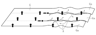
- the glass film is rich in flexibility as it is thinned, but is easily damaged. Therefore, as shown in FIG. 6, when a gas is blown directly onto the glass film G from below, as the cleaving operation progresses, the glass film G rises from the gap between the cleaved surfaces of the individual glass films Ga after the cleaving is completed.
- the glass film Ga flutters greatly while the glass film Ga flutters due to the gas leaked into the glass (arrow A in the figure). Therefore, the cleaved end faces of the glass film Ga adjacent to each other in the width direction rub against each other, and the cleaved end face of the glass film Ga has a defect that causes breakage such as chipping or cracking. There is a risk of cleaving defects such as.
- an object of the present invention is to efficiently cleave a glass film with thermal stress without causing cleaving defects.
- the glass film cleaving method according to the present invention which was created to solve the above-mentioned problems, is the thermal stress generated in the glass film by local heating along the planned cutting line intersecting the width direction of the glass film and cooling of the heating region.
- the initial crack formed at the tip of the cleaving line is advanced along the cleaving line, and the glass film is cleaved.
- the glass film is cleaved in a state where it is lifted and supported while covering the cleaved portion including the cleaved planned line of the glass film from below with the floated resin sheet. .
- the glass film is lifted and supported by the resin sheet levitated by the gas at the time of cutting. And in this state, the cleaving part including the cleaving line of the glass film is covered from below by the resin sheet. Even if the glass sheet is cleaved using thermal stress, the resin sheet is not cut by local heating with a laser or the like, so the sprayed gas is blocked by the resin sheet and flows into the gaps between the cut surfaces of the glass film. There is no. As a result, the broken glass glass does not vibrate greatly while fluttering due to the blown gas, so that the attitude of the glass film is also stabilized.
- the resin sheet is more flexible than the glass sheet.
- the resin sheet may be wider than the glass film, and may protrude to both outer sides in the width direction of the glass film.
- the entire width direction of the lower surface of the glass film is surely covered with the resin sheet. Therefore, when the glass film is cleaved by thermal stress, it is possible to more reliably prevent the gas blown to the resin sheet from flowing into the gaps between the cut sections of the glass film.
- the glass film is curved in the width direction by lifting and supporting the resin sheet, and a non-floating region that is not lifted and supported by the resin sheet is formed in a region excluding the cleaved portion of the glass film. Good.
- the glass film may be curved in the width direction, and a non-floating region that is not lifted and supported by the resin sheet may be formed in a part of the width direction of the glass film. If it does in this way, since the weight of the glass film which must be lifted and supported by the resin sheet is reduced, even if the weight of the glass film is increased, the cleaving operation can be continued without any problem.
- the ears are preferably included in the non-floating region.
- the ear portion is relatively thicker than the center portion (effective portion) in the width direction that can be a product, and the weight per unit length in the width direction is increased. Therefore, the attitude
- the resin sheet will move with the glass film, so it will rub between the glass film and the resin sheet. Therefore, the ratio of scratches caused by rubbing on the lower surface of the glass film, that is, the contact surface of the glass film with the resin sheet, can be reliably reduced.
- the resin sheet is floated by gas at a fixed position, and only the glass film is slid on the resin sheet. You may make it send.
- the resin sheet is preferably formed of a foamed resin.
- the resin sheet has innumerable cavities derived from the foamed resin, the air present in the cavities serves as a heat insulating material. Therefore, the amount of heat generated by local heating or cooling applied to the glass film at the time of cleaving becomes difficult to be radiated to the resin sheet side. Therefore, it is possible to efficiently apply a thermal stress to the glass film, and it is possible to improve the cleaving efficiency of the glass film.
- the local heating is preferably performed by a laser.
- the local heating of the glass film can be efficiently performed by the heat of laser irradiation.
- the laser a carbon dioxide laser is preferably used.
- the absorption wavelength of the glass can be made appropriate, and local heating can be easily performed in a stable state, and the cost is low. It becomes.
- the glass film preferably has a thickness of 300 ⁇ m or less.
- the manufacturing method of the glass roll based on this invention created in order to solve the said subject is along the cutting planned line which cross
- the cleaving step causes the resin sheet to float by blowing a gas from below to the resin sheet. In the state where the glass film is lifted and supported while covering the planned cutting portion including the planned cutting line from below, Characterized in that splitting the film.
- the glass film in the cleaving step, can be efficiently cleaved while preventing cleaving defects in which chipping or cracks occur on the cleaved end face of the glass film for the same reason as described above. Therefore, if the glass film which passed through such a cleaving process is wound up in a roll shape to produce a glass roll, a glass roll having high end face strength can be produced, which is extremely advantageous in practice.
- the supply source for example, a glass roll obtained by winding a glass film in a roll shape, a molding apparatus for continuously forming the glass film, or the like can be used.
- the glass film cleaving apparatus according to the present invention which was created to solve the above-described problems, is the above-mentioned cleaving due to local heating along the planned cutting line intersecting the width direction of the glass film and the thermal stress generated by cooling of the heating region.
- the initial crack formed at the tip of the planned line is advanced along the cleaving planned line, and the resin sheet disposed in the cleaving region of the glass film and the resin
- the gas sheet is levitated and floated from below to the sheet, It is characterized by cleaving the glass film.
- the glass plate to be cleaved becomes thin like a glass film, it can be cleaved efficiently by thermal stress without causing cleaving defects.
- a glass film having a thickness of 300 ⁇ m or less used for an FPD, an organic EL lighting device, a solar cell, or the like is a target to be cut.
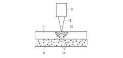
- the thickness of the glass film and the resin sheet that supports the glass film is exaggerated.
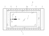
- FIG. 1 (a) and 1 (b) are diagrams showing an implementation status of the glass film cleaving apparatus and the cleaving method according to the first embodiment of the present invention.
- the cleaving apparatus 1 is gripped by a resin sheet R that supports the glass film G from below, a gripping means 2 that grips two sides facing the direction orthogonal to the width direction of the resin sheet R, and a gripping means 2.
- the levitation means 3 is provided to levitate the resin sheet R by blowing a gas from below. Note that the gripping means 2 may be configured to grip all four sides of the resin sheet R.
- the levitation means 3 includes a gas supply source 4 and a levitation stage 6 connected to the gas supply source 4 via a pipe 5.
- a plurality of gas ejection holes 6 a are provided on the upper surface of the levitation stage 6, and the gas supplied from the gas supply source 4 via the pipe 5 is ejected upward from each gas ejection hole 6 a.
- the cutting planned part containing the cutting planned line 7 orthogonal to the width direction of the glass film G is covered from the downward direction by the resin sheet R which floated.
- the glass film G may be positioned on the resin sheet R by bringing a positioning pin (not shown) into contact with the edge of the glass film G.
- the cleaving apparatus 1 includes a heating unit 8 that irradiates a laser beam L from above the glass film G that is lifted and supported by the resin sheet R and performs local heating, and a heating region H heated by the heating unit 8 on the surface side.
- the cooling means 9 which injects the cooling water W from is provided.
- the heating means 8 and the cooling means 9 are scanned along the planned cutting line 7 of the glass film G.
- the heating area H by the heating means 8 and the cooling area C by the cooling means 9 sequentially move on the planned cutting line 7, and thermal stress acts along the planned cutting line 7.
- An initial crack 10 is formed in advance at the tip of the splitting line 7, and the initial crack 10 propagates along the cutting line 7 due to the thermal stress, and the glass film G is cut.
- the gas sprayed from the gas ejection hole 6a of the levitation stage 6 is firstly used.
- the resin sheet R can be reliably cut off.
- the glass film G does not vibrate greatly while fluttering with gas, the attitude of the glass film G can be stabilized.
- the size of the resin sheet R is larger than the glass film G as shown in FIG. That is, the resin sheet R is in a state in which the resin sheet R protrudes outward from the glass film G in both the width direction and the direction orthogonal thereto. Thereby, the entire lower surface of the glass film G is reliably covered with the resin sheet R. Therefore, when the glass film G is cleaved by thermal stress, it is possible to more reliably prevent the gas blown to the resin sheet R from flowing into the gaps between the fractured surfaces of the glass film G.
- the resin sheet R has higher flexibility than the glass film G, and is formed of the following material, for example. That is, the material of the resin sheet R is appropriately selected from the group consisting of copolymers such as polyethylene, polyvinyl chloride, polyvinylidene chloride, polyvinyl alcohol, polypropylene, polyester, polycarbonate, polystyrene, polyamide, and polyethylene copolymers.
- the thickness of the resin sheet R is preferably 1 mm or less.
- the resin sheet R has heat resistance that can withstand the heat applied to the glass film G by the heating means 8. Therefore, in the present embodiment, as shown in FIG. 2, the resin sheet R is formed of a foamed resin obtained by foaming the exemplified resin or the like. Thereby, since the air present in the infinite number of cavities (bubbles) 11 formed inside the resin sheet R plays the role of a heat insulating material, the heat applied by the heating means 8 (heat distribution indicated by reference numeral 12 in the figure) Heat resistance can be easily and reliably imparted to the resin sheet R.
- the expansion ratio of the foamed resin forming the resin sheet R is, for example, 5 to 50 times.
- the floating stage 6 is moved in the state which has arrange
- the heating means 8 may use a laser such as a carbon dioxide laser, but may use other means that can perform other local heating such as heating wire or hot air injection.
- the cooling means 9 may use the cooling water W as a refrigerant by air pressure or the like, but a cooling liquid other than cooling water, a gas such as air or an inert gas, or a mixture of a gas and a liquid Further, a mixture of a solid such as dry ice or ice and the gas and / or the liquid may be used as the refrigerant.
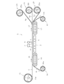
- 3 (a) and 3 (b) are diagrams showing an implementation status of the glass film cleaving apparatus and the cleaving method according to the second embodiment of the present invention.
- the second embodiment is different from the first embodiment in that the cleaving step is performed while feeding the long glass film G.
- a glass roll 13 in which a long glass film G is wound around the core 13a is disposed on the upstream side, and this upstream glass roll 13 is disposed. It is set as the structure which conveys the glass film G unwound from the downstream. And on the conveyance path
- the first conveyor 14 and the second conveyor 15 have the same configuration, and as shown in FIG. 3B, the conveyor belts 16 and 17 have innumerable gas suction holes 16a and 17a.
- a resin roll 18 in which a long resin sheet R is wound around the winding core 18a is disposed below the upstream side of the first conveyor 14, and the resin sheet R unwound from the resin roll 18 is Winding is carried out sequentially around the core 19a of the resin roll 19 which is installed between the conveyor belt 16 of the first conveyor 14 and the conveyor belt 17 of the second conveyor 15 and arranged downstream of the second conveyor 15. It is done. At this time, the resin sheet R is conveyed to the downstream side while being adsorbed by the respective conveyor belts 16 and 17 of the first conveyor 14 and the second conveyor 15.
- the levitation stage 6 blows gas from the gas ejection holes 6 a to the resin sheet R laid between the first conveyor 14 and the second conveyor 15, and causes the resin sheet R to float from the upper surface of the levitation stage 6.
- the glass film G unwound from the glass roll 13 disposed on the upstream side is placed on the resin sheet R laid between the first conveyor 14 and the second conveyor 15, and downstream with the resin sheet R. Conveyed to the side. At this time, the glass film G is lifted and supported by the resin sheet R levitated at a position corresponding to the levitating stage 6, and in this state, the heating film 8 and the cooling element 9 cause thermal stress to act on the glass film G. Cleave.
- the glass films Ga divided into a plurality of pieces are separated from each other on the downstream side of the second conveyor 15, and then moved around the corresponding cores 20 a disposed on the downstream side of the second conveyor 15. It is wound and accommodated again in the state of the glass roll 20.
- the cleaving process is performed on the glass roll 13 by a so-called roll-to-roll method.
- the glass film G unwound from one glass roll 13 is divided into three in the width direction, and three glass rolls 20 are manufactured by the divided glass film Ga.
- FIG. 4 is a diagram showing an implementation status of the glass film cleaving apparatus and the cleaving method according to the third embodiment of the present invention.
- the third embodiment is different from the second embodiment in that the cleaving step is performed as it is on the glass film G drawn from the molding apparatus 21 that molds the glass film G.
- the molding apparatus 21 performs an overflow downdraw method, and in order from the top, a molding zone 21A having a molded body 21x in a molding furnace and a slow cooling zone 21B having an annealing means (annealer). And a cooling zone 21C having a cooling means.
- the glass film G drawn downward from the cooling zone 21 ⁇ / b> C of the forming device 21 is smoothly curved and sent in the lateral direction by the conversion roller 22, and then the first conveyor 14, the second conveyor 15, Is placed on the resin sheet R installed between the two and conveyed downstream. At this time, the glass film G lifted and supported by the resin sheet R that has floated is cut at a position corresponding to the floating stage 6 between the first conveyor 14 and the second conveyor 15.
- the glass film G formed by the forming device 21 is formed with ear portions Gx that are relatively thicker than the effective portion Ga at the center portion in the width direction due to contact of the rollers at both ends in the width direction. . Since this ear
- the molding apparatus 21 may perform other downdraw methods such as a slot downdraw method and a redraw method in addition to the overflow downdraw method.
- the effective portion Ga may be divided into a plurality of parts.
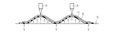
- FIGS. 5 (a) to 5 (c) are diagrams showing the implementation status of the cleaving method by the glass film cleaving apparatus according to the fourth embodiment of the present invention.
- the fourth embodiment is different from the first to third embodiments in that the glass film G is curved in the width direction by lifting and supporting the resin sheet R, and the resin sheet R is partially formed in the width direction of the glass film G. Thus, the non-floating region X which is not lifted and supported is formed.
- the ear part Gx when the ear part Gx is formed at both ends in the width direction of the glass film G, the ear part Gx is preferably set as the non-floating region X. This is because the ear part Gx is relatively thicker and thicker than the effective part Ga at the center in the width direction of the glass film G.
- edge part Gx is finally discarded as demonstrated in 3rd Embodiment, even if it directly grounds the ear
- a protective film may be attached to the surface of the cleaved glass film by lamination or the like.
- the protective film include polyethylene, polyvinyl chloride, polyvinylidene chloride, polyvinyl alcohol, polypropylene, polyester, polycarbonate, polystyrene, polyamide (for example, nylon (trademark)), and copolymers such as polyethylene copolymer.
- a resin layer may be formed on the surface of the glass film by applying a resin to the cut glass film and curing it.
- the resin constituting the resin layer include silicone polymer (silicone resin), sol-gel polymer, polycarbonate, polyether sulfone, polyacrylate, polyimide, cycloolefin copolymer, polyarylate, and the like.
Landscapes
- Chemical & Material Sciences (AREA)
- Engineering & Computer Science (AREA)
- Organic Chemistry (AREA)
- Materials Engineering (AREA)
- Physics & Mathematics (AREA)
- Mechanical Engineering (AREA)
- Optics & Photonics (AREA)
- Health & Medical Sciences (AREA)
- Thermal Sciences (AREA)
- Toxicology (AREA)
- Plasma & Fusion (AREA)
- Re-Forming, After-Treatment, Cutting And Transporting Of Glass Products (AREA)
- Processing Of Stones Or Stones Resemblance Materials (AREA)
- Laser Beam Processing (AREA)
Abstract
Description
2 把持手段
3 浮上手段
4 気体供給源
6 浮上ステージ
6a 気体噴出孔
7 割断予定線
8 加熱手段
9 冷却手段
10 初期亀裂
13,20 ガラスロール
14,15 コンベア
16,17 搬送ベルト
16a,17a 気体吸引孔
18,19 樹脂ロール
21 成形装置
21x 成形体
21A 成形ゾーン
21B 徐冷ゾーン
21C 冷却ゾーン
22 変換ローラ
G ガラスフィルム
Ga 有効部
Gx 耳部
R 樹脂シート
Claims (13)
- ガラスフィルムの幅方向と交差する割断予定線に沿う局部加熱およびその加熱領域の冷却により前記ガラスフィルムに生じる熱応力で、前記割断予定線の先端部に形成した初期亀裂を前記割断予定線に沿って進展させ、前記ガラスフィルムを割断するガラスフィルムの割断方法において、
前記ガラスフィルムの割断領域で、樹脂シートに下方から気体を吹き付けて浮上させるとともに、該浮上した樹脂シートで前記ガラスフィルムの前記割断予定線を含む割断予定部を下方から覆いながら持ち上げ支持した状態で、前記ガラスフィルムを割断することを特徴とするガラスフィルム割断方法。 - 前記樹脂シートが、前記ガラスシートよりも柔軟であることを特徴とする請求項1に記載のガラスフィルム割断方法。
- 前記樹脂シートが、前記ガラスフィルムよりも幅広で、前記ガラスフィルムの幅方向両外方に食み出していることを特徴とする請求項1又は2に記載のガラスフィルムの割断方法。
- 前記樹脂シートの持ち上げ支持により前記ガラスフィルムを幅方向で湾曲させ、前記ガラスフィルムの前記割断予定部を除く領域に、前記樹脂シートにより持ち上げ支持しない非浮上領域を形成したことを特徴とする請求項1~3のいずれか1項に記載のガラスフィルムの割断方法。
- 前記ガラスフィルムが、幅方向両端部に幅方向中央部よりも相対的に厚肉となる耳部を有し、該耳部が前記非浮上領域に含まれていることを特徴とする請求項4に記載のガラスフィルムの割断方法。
- 前記ガラスフィルムを前記樹脂シートで持ち上げ支持した状態で、前記ガラスフィルムと共に前記樹脂シートを送りながら、前記ガラスフィルムを割断することを特徴とする請求項1~5のいずれか1項に記載のガラスフィルムの割断方法。
- 前記樹脂シートが、発泡樹脂で形成されていることを特徴とする請求項1~6のいずれか1項に記載のガラスフィルムの割断方法。
- 前記局部加熱が、レーザーによって行われることを特徴とする請求項1~7のいずれか1項に記載のガラスフィルムの割断方法。
- 前記ガラスフィルムの厚みが、300μm以下であることを特徴とする請求項1~8のいずれか1項に記載のガラスフィルムの割断方法。
- ガラスフィルム供給源から長尺なガラスフィルムを連続的に送り出しながら、前記ガラスフィルムの幅方向と交差する割断予定線に沿う局部加熱およびその加熱領域の冷却により前記ガラスフィルムに生じる熱応力で、前記割断予定線の先端部に形成した初期亀裂を前記割断予定線に沿って進展させ、前記ガラスフィルムを割断する割断工程と、その割断された前記ガラスフィルムをロール状に巻き取る巻取工程とを含むガラスロールの製造方法において、
前記割断工程は、樹脂シートに下方から気体を吹き付けて浮上させるとともに、該浮上した樹脂シートで前記ガラスフィルムの前記割断予定線を含む割断予定部を下方から覆いながら持ち上げ支持した状態で、前記ガラスフィルムを割断することを特徴とするガラスロールの製造方法。 - 前記ガラスフィルム供給源が、ガラスフィルムをロール状に巻回したガラスロールであることを特徴とする請求項10に記載のガラスロールの製造方法。
- 前記ガラスフィルム供給源が、ガラスフィルムを連続的に成形する成形装置であることを特徴とする請求項10に記載のガラスロールの製造方法。
- ガラスフィルムの幅方向と交差する割断予定線に沿う局部加熱及びその加熱領域の冷却により生じる熱応力で、前記割断予定線の先端部に形成した初期亀裂を前記割断予定線に沿って進展させ、前記ガラスフィルムを割断するガラスフィルムの割断装置において、
前記ガラスフィルムの割断領域に配置された樹脂シートと、該樹脂シートに下方から気体を吹き付けて浮上させる浮上手段とを備え、該浮上手段により浮上した前記樹脂シートで前記ガラスフィルムの前記割断予定線を含む割断予定部を下方から覆いながら持ち上げ支持した状態で、前記ガラスフィルムを割断することを特徴とするガラスフィルムの割断装置。
Priority Applications (2)
| Application Number | Priority Date | Filing Date | Title |
|---|---|---|---|
| KR1020137003246A KR20130094298A (ko) | 2010-07-22 | 2011-07-15 | 유리 필름의 할단 방법, 유리 롤의 제조 방법, 및 유리 필름의 할단 장치 |
| CN201180021495.0A CN102858700B (zh) | 2010-07-22 | 2011-07-15 | 玻璃膜的割断方法、玻璃辊的制造方法及玻璃膜的割断装置 |
Applications Claiming Priority (2)
| Application Number | Priority Date | Filing Date | Title |
|---|---|---|---|
| JP2010-165093 | 2010-07-22 | ||
| JP2010165093A JP5669001B2 (ja) | 2010-07-22 | 2010-07-22 | ガラスフィルムの割断方法、ガラスロールの製造方法、及びガラスフィルムの割断装置 |
Publications (1)
| Publication Number | Publication Date |
|---|---|
| WO2012011445A1 true WO2012011445A1 (ja) | 2012-01-26 |
Family
ID=45492443
Family Applications (1)
| Application Number | Title | Priority Date | Filing Date |
|---|---|---|---|
| PCT/JP2011/066241 Ceased WO2012011445A1 (ja) | 2010-07-22 | 2011-07-15 | ガラスフィルムの割断方法、ガラスロールの製造方法、及びガラスフィルムの割断装置 |
Country Status (6)
| Country | Link |
|---|---|
| US (1) | US8312741B2 (ja) |
| JP (1) | JP5669001B2 (ja) |
| KR (1) | KR20130094298A (ja) |
| CN (1) | CN102858700B (ja) |
| TW (1) | TWI498296B (ja) |
| WO (1) | WO2012011445A1 (ja) |
Cited By (4)
| Publication number | Priority date | Publication date | Assignee | Title |
|---|---|---|---|---|
| JP2015044710A (ja) * | 2013-08-28 | 2015-03-12 | 日本電気硝子株式会社 | ガラスフィルムリボン製造装置及びガラスフィルムリボン製造方法並びにガラスロール |
| CN104703933A (zh) * | 2012-10-12 | 2015-06-10 | 株式会社Ihi | 切割装置 |
| CN109202306A (zh) * | 2018-11-26 | 2019-01-15 | 王志超 | 一种板材激光切割机工件托举装置 |
| WO2022070814A1 (ja) * | 2020-10-02 | 2022-04-07 | 日本電気硝子株式会社 | ガラスロールの製造方法 |
Families Citing this family (77)
| Publication number | Priority date | Publication date | Assignee | Title |
|---|---|---|---|---|
| JP5177295B2 (ja) * | 2009-08-07 | 2013-04-03 | 旭硝子株式会社 | 超薄板ガラス基板の製造方法 |
| JP5704395B2 (ja) * | 2010-03-29 | 2015-04-22 | 日本電気硝子株式会社 | ガラスロール梱包体 |
| JP5669001B2 (ja) * | 2010-07-22 | 2015-02-12 | 日本電気硝子株式会社 | ガラスフィルムの割断方法、ガラスロールの製造方法、及びガラスフィルムの割断装置 |
| JP5617556B2 (ja) * | 2010-11-22 | 2014-11-05 | 日本電気硝子株式会社 | 帯状ガラスフィルム割断装置及び帯状ガラスフィルム割断方法 |
| US20140054348A1 (en) * | 2011-06-08 | 2014-02-27 | Yasuo Teranishi | Method for cutting plate-like glass, and cutting device therefor |
| KR20150045957A (ko) * | 2012-08-21 | 2015-04-29 | 아사히 가라스 가부시키가이샤 | 복합 시트의 절단 방법, 유리 시트의 절단 방법, 복합 시트의 절단편 |
| TW201412658A (zh) * | 2012-09-26 | 2014-04-01 | Corning Inc | 用於可撓式玻璃帶之邊緣修正管理 |
| KR20150063418A (ko) * | 2012-09-26 | 2015-06-09 | 코닝 인코포레이티드 | 가요성 리본 구성부를 제조하고 분리하는 방법 및 그 기기 |
| US9216924B2 (en) * | 2012-11-09 | 2015-12-22 | Corning Incorporated | Methods of processing a glass ribbon |
| KR20150084758A (ko) * | 2012-11-13 | 2015-07-22 | 니폰 덴키 가라스 가부시키가이샤 | 판 유리의 제조 방법 및 제조 장치 |
| WO2014079478A1 (en) | 2012-11-20 | 2014-05-30 | Light In Light Srl | High speed laser processing of transparent materials |
| WO2014085357A1 (en) * | 2012-11-29 | 2014-06-05 | Corning Incorporated | Methods and apparatus for fabricating glass ribbon of varying widths |
| EP2754524B1 (de) | 2013-01-15 | 2015-11-25 | Corning Laser Technologies GmbH | Verfahren und Vorrichtung zum laserbasierten Bearbeiten von flächigen Substraten, d.h. Wafer oder Glaselement, unter Verwendung einer Laserstrahlbrennlinie |
| CN105189022B (zh) * | 2013-01-30 | 2017-09-01 | 康宁股份有限公司 | 用于柔性玻璃连续激光切割的设备和方法 |
| JP2014159352A (ja) * | 2013-02-20 | 2014-09-04 | Nitto Denko Corp | 可撓性フィルムの製造方法 |
| CN105593014A (zh) * | 2013-03-14 | 2016-05-18 | 康宁股份有限公司 | 用于制造和切割挠性玻璃和聚合物复合结构的方法和设备 |
| US20160137543A1 (en) * | 2013-03-20 | 2016-05-19 | Coming Incorporated | Apparatus and method for processing lengths of flexible glass |
| EP2781296B1 (de) | 2013-03-21 | 2020-10-21 | Corning Laser Technologies GmbH | Vorrichtung und verfahren zum ausschneiden von konturen aus flächigen substraten mittels laser |
| DE102013108308A1 (de) * | 2013-08-01 | 2015-02-19 | Schott Ag | Verfahren und Vorrichtung zur Detektion in Bandrollen aus sprödhartem oder sprödbrechendem, zumindest teiltransparentem Material, sowie deren Verwendung |
| EP3040317B1 (en) * | 2013-08-28 | 2019-09-25 | Nippon Electric Glass Co., Ltd. | Glass film ribbon manufacturing method and glass film ribbon manufacturing device |
| JP6222439B2 (ja) * | 2013-10-04 | 2017-11-01 | 日本電気硝子株式会社 | ガラスフィルムの割断方法及びフィルム状ガラスの製造方法 |
| CN103567645B (zh) * | 2013-11-13 | 2016-01-13 | 江苏华风电子有限公司 | 膜片激光切割装置 |
| WO2015072259A1 (ja) | 2013-11-14 | 2015-05-21 | 三菱電機株式会社 | レーザ加工方法およびレーザ加工装置 |
| US9701563B2 (en) | 2013-12-17 | 2017-07-11 | Corning Incorporated | Laser cut composite glass article and method of cutting |
| US10442719B2 (en) | 2013-12-17 | 2019-10-15 | Corning Incorporated | Edge chamfering methods |
| US10293436B2 (en) | 2013-12-17 | 2019-05-21 | Corning Incorporated | Method for rapid laser drilling of holes in glass and products made therefrom |
| US20150165560A1 (en) | 2013-12-17 | 2015-06-18 | Corning Incorporated | Laser processing of slots and holes |
| US9850160B2 (en) | 2013-12-17 | 2017-12-26 | Corning Incorporated | Laser cutting of display glass compositions |
| US11556039B2 (en) | 2013-12-17 | 2023-01-17 | Corning Incorporated | Electrochromic coated glass articles and methods for laser processing the same |
| US9676167B2 (en) | 2013-12-17 | 2017-06-13 | Corning Incorporated | Laser processing of sapphire substrate and related applications |
| US9815730B2 (en) | 2013-12-17 | 2017-11-14 | Corning Incorporated | Processing 3D shaped transparent brittle substrate |
| US20150251944A1 (en) * | 2014-03-10 | 2015-09-10 | Corning Incorporated | Methods and apparatuses for separating glass ribbons |
| JP6269830B2 (ja) * | 2014-06-11 | 2018-01-31 | 株式会社Ihi | 脆性材料基板の割断方法及び脆性材料基板の割断装置 |
| TWI730945B (zh) | 2014-07-08 | 2021-06-21 | 美商康寧公司 | 用於雷射處理材料的方法與設備 |
| EP3169479B1 (en) | 2014-07-14 | 2019-10-02 | Corning Incorporated | Method of and system for arresting incident crack propagation in a transparent material |
| CN107073641B (zh) | 2014-07-14 | 2020-11-10 | 康宁股份有限公司 | 接口块;用于使用这种接口块切割在波长范围内透明的衬底的系统和方法 |
| WO2016010949A1 (en) | 2014-07-14 | 2016-01-21 | Corning Incorporated | Method and system for forming perforations |
| KR20170028943A (ko) * | 2014-07-14 | 2017-03-14 | 코닝 인코포레이티드 | 조정가능한 레이저 빔 촛점 라인을 사용하여 투명한 재료를 처리하는 방법 및 시스템 |
| WO2016011114A1 (en) * | 2014-07-18 | 2016-01-21 | Corning Incorporated | Methods and apparatus for controlled laser cutting of flexible glass |
| JP2016102048A (ja) * | 2014-11-13 | 2016-06-02 | 三星ダイヤモンド工業株式会社 | スクライブ方法並びにスクライブ装置 |
| US10047001B2 (en) | 2014-12-04 | 2018-08-14 | Corning Incorporated | Glass cutting systems and methods using non-diffracting laser beams |
| CN107406293A (zh) | 2015-01-12 | 2017-11-28 | 康宁股份有限公司 | 使用多光子吸收方法来对经热回火的基板进行激光切割 |
| US9843014B2 (en) * | 2015-02-20 | 2017-12-12 | Apple Inc. | Electronic devices with sapphire-coated substrates |
| US11773004B2 (en) | 2015-03-24 | 2023-10-03 | Corning Incorporated | Laser cutting and processing of display glass compositions |
| KR20170131638A (ko) | 2015-03-27 | 2017-11-29 | 코닝 인코포레이티드 | 가스 투과성 유리창 및 이의 제작방법 |
| DE102015104815A1 (de) | 2015-03-27 | 2016-09-29 | Schott Ag | Verfahren und Vorrichtung zum kontinuierlichen Trennen von Glas |
| WO2017011296A1 (en) | 2015-07-10 | 2017-01-19 | Corning Incorporated | Methods of continuous fabrication of holes in flexible substrate sheets and products relating to the same |
| JP6613677B2 (ja) * | 2015-07-17 | 2019-12-04 | 三星ダイヤモンド工業株式会社 | 脆性基板の分断方法及び分断装置 |
| JP2017088467A (ja) * | 2015-11-16 | 2017-05-25 | 旭硝子株式会社 | ガラス基板に孔を形成する装置および方法 |
| DE102015225929B4 (de) * | 2015-12-18 | 2018-01-04 | Fraunhofer-Gesellschaft zur Förderung der angewandten Forschung e.V. | Verfahren zur Überprüfung eines Trennschrittes bei der Zerteilung eines flachen Werkstückes in Teilstücke |
| JP6938543B2 (ja) | 2016-05-06 | 2021-09-22 | コーニング インコーポレイテッド | 透明基板からの、輪郭設定された形状のレーザ切断及び取り外し |
| JP6579040B2 (ja) * | 2016-05-31 | 2019-09-25 | 日本電気硝子株式会社 | ガラスロールの製造方法 |
| US10410883B2 (en) | 2016-06-01 | 2019-09-10 | Corning Incorporated | Articles and methods of forming vias in substrates |
| US10794679B2 (en) | 2016-06-29 | 2020-10-06 | Corning Incorporated | Method and system for measuring geometric parameters of through holes |
| KR20190035805A (ko) | 2016-07-29 | 2019-04-03 | 코닝 인코포레이티드 | 레이저 처리를 위한 장치 및 방법 |
| KR102423775B1 (ko) | 2016-08-30 | 2022-07-22 | 코닝 인코포레이티드 | 투명 재료의 레이저 가공 |
| US10730783B2 (en) | 2016-09-30 | 2020-08-04 | Corning Incorporated | Apparatuses and methods for laser processing transparent workpieces using non-axisymmetric beam spots |
| KR102428350B1 (ko) | 2016-10-24 | 2022-08-02 | 코닝 인코포레이티드 | 시트형 유리 기판의 레이저 기반 기계 가공을 위한 기판 프로세싱 스테이션 |
| US10752534B2 (en) | 2016-11-01 | 2020-08-25 | Corning Incorporated | Apparatuses and methods for laser processing laminate workpiece stacks |
| US20180118602A1 (en) * | 2016-11-01 | 2018-05-03 | Corning Incorporated | Glass sheet transfer apparatuses for laser-based machining of sheet-like glass substrates |
| US10688599B2 (en) | 2017-02-09 | 2020-06-23 | Corning Incorporated | Apparatus and methods for laser processing transparent workpieces using phase shifted focal lines |
| JP6829814B2 (ja) * | 2017-03-13 | 2021-02-17 | 日本電気硝子株式会社 | ガラスフィルムの製造方法 |
| JP6748920B2 (ja) * | 2017-03-13 | 2020-09-02 | 日本電気硝子株式会社 | ガラスフィルムの製造方法 |
| US10580725B2 (en) | 2017-05-25 | 2020-03-03 | Corning Incorporated | Articles having vias with geometry attributes and methods for fabricating the same |
| US11078112B2 (en) | 2017-05-25 | 2021-08-03 | Corning Incorporated | Silica-containing substrates with vias having an axially variable sidewall taper and methods for forming the same |
| US10626040B2 (en) | 2017-06-15 | 2020-04-21 | Corning Incorporated | Articles capable of individual singulation |
| JP6839419B2 (ja) * | 2017-07-31 | 2021-03-10 | 日本電気硝子株式会社 | ガラスフィルムの製造方法 |
| US12180108B2 (en) | 2017-12-19 | 2024-12-31 | Corning Incorporated | Methods for etching vias in glass-based articles employing positive charge organic molecules |
| US11554984B2 (en) | 2018-02-22 | 2023-01-17 | Corning Incorporated | Alkali-free borosilicate glasses with low post-HF etch roughness |
| JP7022389B2 (ja) * | 2018-05-31 | 2022-02-18 | 日本電気硝子株式会社 | ガラスフィルムの製造方法 |
| JP7003385B2 (ja) * | 2018-05-31 | 2022-01-20 | 日本電気硝子株式会社 | ガラスフィルムの製造方法 |
| CN113631372B (zh) * | 2019-03-29 | 2024-01-30 | 日东电工株式会社 | 玻璃膜复合体的搬送方法 |
| WO2021131559A1 (ja) * | 2019-12-24 | 2021-07-01 | 日本電気硝子株式会社 | ガラスフィルムの製造方法、ガラスロールの製造方法、及びガラスフィルムの製造装置 |
| US20230030304A1 (en) * | 2020-01-08 | 2023-02-02 | Nippon Electric Glass Co., Ltd. | Glass film manufacturing method and glass film manufacturing device |
| CN111762398B (zh) * | 2020-07-15 | 2022-04-29 | 高世生 | 一种中空玻璃膜智能加工包装设备 |
| KR102229401B1 (ko) * | 2020-08-28 | 2021-03-18 | 주식회사 재현이노텍 | 가죽 검사장치 및 이를 이용한 가죽 검사방법 |
| CN116583486B (zh) * | 2020-11-24 | 2026-01-16 | 康宁股份有限公司 | 用于制造玻璃带的方法和装置 |
Citations (6)
| Publication number | Priority date | Publication date | Assignee | Title |
|---|---|---|---|---|
| JP2004182530A (ja) * | 2002-12-03 | 2004-07-02 | Nippon Emikku:Kk | 切断方法及び切断装置 |
| JP2005212364A (ja) * | 2004-01-30 | 2005-08-11 | Shibaura Mechatronics Corp | 脆性材料の割断加工システム及びその方法 |
| JP2007090860A (ja) * | 2005-09-01 | 2007-04-12 | Shibaura Mechatronics Corp | 脆性材料の割断加工システム及びその方法 |
| JP2007191363A (ja) * | 2006-01-20 | 2007-08-02 | Toshiba Corp | レーザー割断装置、割断方法 |
| JP2007246298A (ja) * | 2006-03-13 | 2007-09-27 | Shibuya Kogyo Co Ltd | 脆性材料の割断方法とその装置 |
| JP2010105900A (ja) * | 2008-10-01 | 2010-05-13 | Nippon Electric Glass Co Ltd | ガラスロール及びその製造方法 |
Family Cites Families (36)
| Publication number | Priority date | Publication date | Assignee | Title |
|---|---|---|---|---|
| US2457785A (en) * | 1944-08-18 | 1948-12-28 | Owens Corning Fiberglass Corp | Apparatus for making glass film |
| DE1244346B (de) * | 1964-10-19 | 1967-07-13 | Menzel Gerhard Glasbearbeitung | Verfahren zum Schneiden von Glas |
| US3795572A (en) * | 1972-05-26 | 1974-03-05 | Ppg Industries Inc | Method of cutting glass and article made thereby |
| US4828900A (en) * | 1987-12-23 | 1989-05-09 | Ppg Industries, Inc. | Discrete glass cutting and edge shaping |
| US4749400A (en) * | 1986-12-12 | 1988-06-07 | Ppg Industries, Inc. | Discrete glass sheet cutting |
| US4743284A (en) * | 1986-12-29 | 1988-05-10 | Ppg Industries, Inc. | Ribbon severing support |
| JP3125444B2 (ja) | 1992-06-17 | 2001-01-15 | 旭化成工業株式会社 | 新規な合わせガラス |
| US5421450A (en) * | 1994-05-31 | 1995-06-06 | Chukoh Chemical Industries, Ltd. | Heat-resistant, laminated conveyer belt |
| US6101845A (en) * | 1996-02-29 | 2000-08-15 | Asahi Glass Company Ltd. | Process for forming a glass sheet |
| DE19649488A1 (de) * | 1996-11-29 | 1997-11-06 | Schott Glaswerke | Vorrichtung zur Handhabung von dünnen Glasscheiben |
| AT406046B (de) * | 1998-02-24 | 2000-01-25 | Lisec Peter | Vorrichtung zum transportieren und kühlen von glasscheiben |
| EP1048628A1 (de) * | 1999-04-30 | 2000-11-02 | Schott Glas | Polymerbeschichtete Dünnglasfoliensubstrate |
| DE10016628A1 (de) * | 2000-04-04 | 2001-10-18 | Schott Glas | Verfahren zum Herstellen von kleinen Dünnglasscheiben und größere Dünnglasscheibe als Halbfabrikat für dieses Herstellen |
| JP2003034545A (ja) | 2001-07-18 | 2003-02-07 | Seiko Epson Corp | レーザ割断装置及び方法、並びに電気光学パネルの割断方法 |
| JP4178443B2 (ja) * | 2002-06-24 | 2008-11-12 | 旭硝子株式会社 | 板硝子の製造方法及び装置 |
| US7005317B2 (en) * | 2003-10-27 | 2006-02-28 | Intel Corporation | Controlled fracture substrate singulation |
| JP4425000B2 (ja) * | 2004-01-06 | 2010-03-03 | 株式会社ブリヂストン | ゴム部材搬送装置、及びそれを有するゴム部材供給システム |
| US7169691B2 (en) * | 2004-01-29 | 2007-01-30 | Micron Technology, Inc. | Method of fabricating wafer-level packaging with sidewall passivation and related apparatus |
| JP4514490B2 (ja) * | 2004-03-29 | 2010-07-28 | 日東電工株式会社 | 半導体ウエハの小片化方法 |
| US7231786B2 (en) * | 2004-07-29 | 2007-06-19 | Corning Incorporated | Process and device for manufacturing glass sheet |
| JP5092337B2 (ja) * | 2006-10-06 | 2012-12-05 | 富士ゼロックス株式会社 | 無端ベルト及びその製造方法、画像形成装置、中間転写ベルト、転写搬送ベルト、並びに、搬送装置 |
| DE102007025893B4 (de) * | 2007-06-01 | 2014-08-21 | Schott Ag | Glaskeramisches Panzermaterial und Verfahren zur Herstellung einer Panzerung mit einer Glaskeramik-Komponente |
| EP2204355A4 (en) * | 2007-10-30 | 2012-10-31 | Asahi Glass Co Ltd | Processes for producing glass/resin composite |
| JP5691148B2 (ja) | 2008-10-01 | 2015-04-01 | 日本電気硝子株式会社 | ガラスロール、ガラスロールの製造装置、及びガラスロールの製造方法 |
| JP5532506B2 (ja) | 2008-10-01 | 2014-06-25 | 日本電気硝子株式会社 | ガラスロール |
| JP5435267B2 (ja) * | 2008-10-01 | 2014-03-05 | 日本電気硝子株式会社 | ガラスロール、ガラスロールの製造装置、及びガラスロールの製造方法 |
| JP5532507B2 (ja) * | 2008-10-01 | 2014-06-25 | 日本電気硝子株式会社 | ガラスロール及びガラスロールの処理方法 |
| JP5788134B2 (ja) | 2008-10-01 | 2015-09-30 | 日本電気硝子株式会社 | ガラスロール及びガラスロールの製造方法 |
| US8656738B2 (en) * | 2008-10-31 | 2014-02-25 | Corning Incorporated | Glass sheet separating device |
| US20100215936A1 (en) * | 2009-02-20 | 2010-08-26 | Canale Joseph E | Coating for inhibiting glass to glass adherence |
| US20110023548A1 (en) * | 2009-07-29 | 2011-02-03 | Garner Sean M | Glass substrate comprising an edge web portion |
| US8833950B2 (en) * | 2010-01-19 | 2014-09-16 | Guardian Industries Corp. | Secondary reflector panel (SRP) with heat-treatable coating for concentrated solar power applications, and/or methods of making the same |
| JP5720885B2 (ja) * | 2010-03-03 | 2015-05-20 | 日本電気硝子株式会社 | ガラスロール、及びガラスロールの製造方法 |
| JP2011190132A (ja) * | 2010-03-12 | 2011-09-29 | Nippon Electric Glass Co Ltd | ガラスロール及びその製造方法 |
| JP5669001B2 (ja) * | 2010-07-22 | 2015-02-12 | 日本電気硝子株式会社 | ガラスフィルムの割断方法、ガラスロールの製造方法、及びガラスフィルムの割断装置 |
| JP5696393B2 (ja) * | 2010-08-02 | 2015-04-08 | 日本電気硝子株式会社 | ガラスフィルムの割断方法 |
-
2010
- 2010-07-22 JP JP2010165093A patent/JP5669001B2/ja not_active Expired - Fee Related
-
2011
- 2011-07-15 WO PCT/JP2011/066241 patent/WO2012011445A1/ja not_active Ceased
- 2011-07-15 CN CN201180021495.0A patent/CN102858700B/zh not_active Expired - Fee Related
- 2011-07-15 KR KR1020137003246A patent/KR20130094298A/ko not_active Ceased
- 2011-07-19 US US13/185,673 patent/US8312741B2/en active Active
- 2011-07-20 TW TW100125597A patent/TWI498296B/zh not_active IP Right Cessation
Patent Citations (6)
| Publication number | Priority date | Publication date | Assignee | Title |
|---|---|---|---|---|
| JP2004182530A (ja) * | 2002-12-03 | 2004-07-02 | Nippon Emikku:Kk | 切断方法及び切断装置 |
| JP2005212364A (ja) * | 2004-01-30 | 2005-08-11 | Shibaura Mechatronics Corp | 脆性材料の割断加工システム及びその方法 |
| JP2007090860A (ja) * | 2005-09-01 | 2007-04-12 | Shibaura Mechatronics Corp | 脆性材料の割断加工システム及びその方法 |
| JP2007191363A (ja) * | 2006-01-20 | 2007-08-02 | Toshiba Corp | レーザー割断装置、割断方法 |
| JP2007246298A (ja) * | 2006-03-13 | 2007-09-27 | Shibuya Kogyo Co Ltd | 脆性材料の割断方法とその装置 |
| JP2010105900A (ja) * | 2008-10-01 | 2010-05-13 | Nippon Electric Glass Co Ltd | ガラスロール及びその製造方法 |
Cited By (10)
| Publication number | Priority date | Publication date | Assignee | Title |
|---|---|---|---|---|
| CN104703933A (zh) * | 2012-10-12 | 2015-06-10 | 株式会社Ihi | 切割装置 |
| CN104703933B (zh) * | 2012-10-12 | 2017-03-15 | 株式会社 Ihi | 切割装置 |
| JP2015044710A (ja) * | 2013-08-28 | 2015-03-12 | 日本電気硝子株式会社 | ガラスフィルムリボン製造装置及びガラスフィルムリボン製造方法並びにガラスロール |
| CN109202306A (zh) * | 2018-11-26 | 2019-01-15 | 王志超 | 一种板材激光切割机工件托举装置 |
| CN109202306B (zh) * | 2018-11-26 | 2020-08-25 | 郑州力锋自动化设备有限公司 | 一种板材激光切割机工件托举装置 |
| WO2022070814A1 (ja) * | 2020-10-02 | 2022-04-07 | 日本電気硝子株式会社 | ガラスロールの製造方法 |
| KR20230078952A (ko) * | 2020-10-02 | 2023-06-05 | 니폰 덴키 가라스 가부시키가이샤 | 유리 롤의 제조 방법 |
| TWI832089B (zh) * | 2020-10-02 | 2024-02-11 | 日商日本電氣硝子股份有限公司 | 玻璃卷的製造方法 |
| JP7545639B2 (ja) | 2020-10-02 | 2024-09-05 | 日本電気硝子株式会社 | ガラスロールの製造方法 |
| KR102889365B1 (ko) * | 2020-10-02 | 2025-11-21 | 니폰 덴키 가라스 가부시키가이샤 | 유리 롤의 제조 방법 |
Also Published As
| Publication number | Publication date |
|---|---|
| TW201213257A (en) | 2012-04-01 |
| JP5669001B2 (ja) | 2015-02-12 |
| US20120017642A1 (en) | 2012-01-26 |
| KR20130094298A (ko) | 2013-08-23 |
| TWI498296B (zh) | 2015-09-01 |
| JP2012025614A (ja) | 2012-02-09 |
| US8312741B2 (en) | 2012-11-20 |
| CN102858700B (zh) | 2015-09-09 |
| CN102858700A (zh) | 2013-01-02 |
Similar Documents
| Publication | Publication Date | Title |
|---|---|---|
| JP5669001B2 (ja) | ガラスフィルムの割断方法、ガラスロールの製造方法、及びガラスフィルムの割断装置 | |
| KR101800224B1 (ko) | 판형상 유리의 절단방법 및 그 절단장치 | |
| CN103347827B (zh) | 板状玻璃的切断方法及其切断装置 | |
| TWI576295B (zh) | 玻璃卷的製造方法與玻璃卷 | |
| US9656901B2 (en) | Method of manufacturing a glass roll | |
| JP5510650B2 (ja) | ガラスフィルムの割断方法及び製造方法 | |
| JP5532219B2 (ja) | 板状ガラスの切断方法及びその切断装置 | |
| WO2012070422A1 (ja) | 帯状ガラスフィルム割断装置及び帯状ガラスフィルム割断方法 | |
| JP2011144093A (ja) | 板状ガラスの製造方法及びその装置 | |
| JP2011116611A (ja) | 板状ガラスの切断方法及びその切断装置 | |
| KR20130133756A (ko) | 유리 필름의 할단 방법 | |
| JP2014073961A (ja) | 板状ガラスの切断方法及びその切断装置 | |
| JP6327580B2 (ja) | ガラスフィルム積層体および電子デバイスの製造方法 | |
| TWI492908B (zh) | 板狀玻璃的切割方法以及其切割裝置 |
Legal Events
| Date | Code | Title | Description |
|---|---|---|---|
| WWE | Wipo information: entry into national phase |
Ref document number: 201180021495.0 Country of ref document: CN |
|
| 121 | Ep: the epo has been informed by wipo that ep was designated in this application |
Ref document number: 11809615 Country of ref document: EP Kind code of ref document: A1 |
|
| NENP | Non-entry into the national phase |
Ref country code: DE |
|
| ENP | Entry into the national phase |
Ref document number: 20137003246 Country of ref document: KR Kind code of ref document: A |
|
| 122 | Ep: pct application non-entry in european phase |
Ref document number: 11809615 Country of ref document: EP Kind code of ref document: A1 |