WO2012008481A1 - 加熱調理器および表示装置 - Google Patents
加熱調理器および表示装置 Download PDFInfo
- Publication number
- WO2012008481A1 WO2012008481A1 PCT/JP2011/065953 JP2011065953W WO2012008481A1 WO 2012008481 A1 WO2012008481 A1 WO 2012008481A1 JP 2011065953 W JP2011065953 W JP 2011065953W WO 2012008481 A1 WO2012008481 A1 WO 2012008481A1
- Authority
- WO
- WIPO (PCT)
- Prior art keywords
- image
- cooking
- display
- display unit
- displayed
- Prior art date
- Legal status (The legal status is an assumption and is not a legal conclusion. Google has not performed a legal analysis and makes no representation as to the accuracy of the status listed.)
- Ceased
Links
Images








Classifications
-
- F—MECHANICAL ENGINEERING; LIGHTING; HEATING; WEAPONS; BLASTING
- F24—HEATING; RANGES; VENTILATING
- F24C—DOMESTIC STOVES OR RANGES ; DETAILS OF DOMESTIC STOVES OR RANGES, OF GENERAL APPLICATION
- F24C7/00—Stoves or ranges heated by electric energy
- F24C7/08—Arrangement or mounting of control or safety devices
- F24C7/082—Arrangement or mounting of control or safety devices on ranges, e.g. control panels, illumination
-
- H—ELECTRICITY
- H05—ELECTRIC TECHNIQUES NOT OTHERWISE PROVIDED FOR
- H05B—ELECTRIC HEATING; ELECTRIC LIGHT SOURCES NOT OTHERWISE PROVIDED FOR; CIRCUIT ARRANGEMENTS FOR ELECTRIC LIGHT SOURCES, IN GENERAL
- H05B6/00—Heating by electric, magnetic or electromagnetic fields
- H05B6/64—Heating using microwaves
- H05B6/6435—Aspects relating to the user interface of the microwave heating apparatus
Definitions
- the present invention relates to a heating cooker and also relates to a display device used for, for example, a heating cooker.
- a display device there is a display device mounted on a heating cooker described in JP-A-2002-349858 (Patent Document 1).
- This display device includes a display unit provided on the front surface of the casing of the heating cooker, and a plurality of keys for switching an image displayed by the display unit.
- the user can switch the image on the display unit to another image by operating a plurality of keys, and display a desired image on the display unit.
- the conventional display device has a problem that it is difficult to switch images because a plurality of keys need to be operated.
- an object of the present invention is to provide a cooking device and a display device that can easily switch an image on a display unit by an intuitive operation.
- the heating cooker of the present invention is A cooking recipe storage unit for storing a plurality of cooking recipes; A display unit for displaying a part of the cooking recipe stored in the cooking recipe storage unit; A touch panel; A display control device for sequentially switching the cooking recipe to be displayed on the display unit by an operation of sliding while touching the surface of the touch panel with a finger or a contact; A cooking and cooking unit that performs cooking based on the cooking recipe selected on the touch panel; It is characterized by having.
- the display control device sequentially switches the cooking recipe to be displayed on the display unit by an operation of sliding while touching the surface of the touch panel with a finger or a contact object. It is possible to easily switch the image of the part.
- the image of the cooking recipe can be easily switched, it is easy to find the image of the target cooking recipe. Therefore, the switching and selection of the image can be performed with low stress.
- the touch panel covers at least a part of the display unit,
- the touch panel has an instantaneous switching area for switching the cooking image displayed on the display unit even when the finger or the contact object does not slide on the surface.
- the touch panel has an instantaneous switching area for switching a cooking image displayed on the display unit even when a finger or a contact object does not slide on the surface of the touch panel.
- the cooking image of the part can be switched quickly. Therefore, it is possible to reduce the time and burden required to display the target cooking image on the display unit.
- the display control device is a standard for predicting the number of times that a finger or a contact must touch the surface of the touch panel before moving from the cooking image displayed on the display unit to another target cooking image. Further controlling the display so that the display displays information,
- the information includes a number previously associated with the cooking image displayed on the display unit, a category previously associated with the cooking image displayed on the display unit, and a cooking image displayed on the display unit. It is at least one of the number of calories associated in advance.
- the display control device determines the number of times that a finger or a contact must touch the surface of the touch panel before moving from the cooking image displayed on the display unit to another cooking image.
- the display unit is further controlled so that the display unit displays information that is a guideline for prediction. Therefore, the user who has reduced time and burden among the operation of sliding the finger or the contact object while touching the surface of the touch panel and the operation of not moving the finger or the contact object by touching the surface of the touch panel, You can choose exactly.
- the user must touch the surface of the touch panel before moving from the cooking image displayed on the display unit to another cooking image based on the information displayed on the display unit. You can predict how many times you will not.
- the information includes the number previously associated with the cooking image displayed on the display unit, the category previously associated with the cooking image displayed on the display unit, and the cooking image displayed on the display unit. Since it is at least one of the number of calories associated in advance, the accuracy of the prediction can be improved.
- the display control device determines that the state in which the finger or the contact object does not slide by touching the surface of the touch panel continues for a preset time, the display control device has a speed of switching the cooking image displayed on the display unit.
- the display unit is controlled to rise.
- the display control device determines that the state in which the finger or the contact object does not slide by touching the surface of the touch panel continues for a preset time, the cooking displayed on the display unit Since the display unit is controlled so that the image switching speed increases, it is possible to further reduce the time and burden required to display the target cooking image on the display unit.
- the display control device After the display control device increases the switching speed of the cooking image displayed on the display unit, the state where the finger or the contact object does not slide by touching the touch panel continues for a preset time. If it judges that it is, the said display part is controlled so that the speed which switches the cooking image currently displayed on the said display part rises further.
- the display control device increases the speed at which the cooking image displayed on the display unit is switched, a state in which a finger or a contact object does not slide by touching the touch panel is set in advance. If it is determined that the cooking time is continued, the display unit is controlled so as to further increase the speed of switching the cooking image displayed on the display unit. Therefore, the time required for displaying the target cooking image on the display unit. And the effect which reduces a burden can be heightened.
- the display control device changes the speed or the number of switching images according to the speed at which the finger or the contact object slides.
- the display control device changes the speed or number of switching images according to the speed at which the finger or the contact object slides, so that the user can adjust the speed or number of switching of images. Therefore, the usability of the cooking device can be improved.
- a sound output unit that outputs sound in response to a user's finger touching the touch panel; When the display unit repeatedly displays a plurality of cooking images in a preset order, when the last cooking image of the plurality of cooking images disappears, the display of the last cooking image is finished.
- a characteristic sound output control unit that causes the sound output unit to output a characteristic sound representing the above.
- the characteristic sound output control unit outputs a characteristic sound indicating that the display of the last cooking image is finished when the last cooking image of the plurality of cooking images disappears. Since it is made to output to an output part, a user can notice easily that the display of the cooking image of the last order was finished.
- the display device of the present invention includes: A display unit; A touch panel covering at least a part of the display unit; A display control device for controlling the display unit; A key input unit for switching an image displayed on the display unit, The display control device When the touch panel is flicked, a flick display control unit that flicks an image displayed on the display unit; A key input display control unit that switches the images displayed on the display unit one after another in response to an input from the key input unit; An information display control unit that displays information on the display unit as a guideline for predicting the number of flick operations before moving from the image displayed on the display unit to another target image. Yes.
- “flick input” means input by an operation of gently touching the surface of the touch panel with, for example, a finger or a touch pen.
- the flick display control unit of the display control device flicks the image on the display unit in response to a flick input to the touch panel, so that the image on the display unit can be easily switched by an intuitive operation. be able to.
- the key input display control unit of the display control device sequentially switches the image of the display unit in accordance with the input of the key input unit, the image of the display unit can be switched quickly. Therefore, it is possible to reduce the time and burden required to display the target image on the display unit.
- the information display control unit of the display control device displays information on the display unit as a guideline for predicting the number of flick operations before moving from the image displayed on the display unit to another target image. Therefore, the user can accurately select the flick input to the touch panel and the input to the key input unit that require less time and burden.
- the key input display control unit determines that the key input unit is continuously input for a preset time
- the key input display control unit includes a high-speed switching display control unit that increases a switching speed of the image displayed on the display unit. Including.
- the high-speed switching display control unit of the key input display control unit determines that the key input unit is continuously input for a preset time, the image displayed on the display unit is displayed. Since the switching speed is increased, the time and burden required to display the target image on the display unit can be further reduced.
- the high-speed switching display control unit increases the speed of switching the image displayed on the display unit and further determines that the key input unit is continuously input for a preset time, The speed of switching the image displayed on the display unit is further increased.
- the user can input the key input unit continuously for a preset time, thereby switching the image. Since the speed further increases, it is possible to enhance the effect of reducing the time and burden required to display the target image on the display unit.
- the information is associated in advance with a number associated with an image displayed on the display unit, a category associated with an image displayed on the display unit, and an image displayed on the display unit. At least one of the number of calories burned.
- the user predicts the number of flick operations until the user moves from the image displayed on the display unit to another target image based on the information displayed on the display unit.
- the information is previously associated with a number associated with an image displayed on the display unit, a category associated with an image displayed on the display unit, and an image displayed on the display unit. Since it is at least one of the calculated calorie numbers, the accuracy of the prediction can be improved.
- the display device of one embodiment Provided with a sound output unit that outputs sound according to the input of the key input unit, When the display unit repeatedly displays a plurality of images in a preset order, when the last order image of the plurality of images disappears, it represents that the display of the last order image has been completed A characteristic sound output control unit that causes the sound output unit to output sound is included.
- the characteristic sound output control unit outputs a characteristic sound indicating that the display of the last order image is finished when the last order image of the plurality of images disappears. Therefore, the user can easily notice that the display of the last image is finished.
- the display control device sequentially switches the cooking recipe to be displayed on the display unit by an operation of sliding while touching the surface of the touch panel with a finger or a contact object. It is possible to easily switch the image on the display unit.
- the image of the cooking recipe can be easily switched, it is easy to find the image of the target cooking recipe. Therefore, the switching and selection of the image can be performed with low stress.
- the display device of the present invention includes a display unit, a touch panel that covers the display unit, a display control device that controls the display unit, and a key input unit that switches an image displayed on the display unit. Since this display control device has a flick display control unit that flicks an image displayed on the display unit when the touch panel is flicked, the user can easily switch the image on the display unit by an intuitive operation. be able to.
- the display control device has a key input display control unit that switches the images displayed on the display unit one after another according to the input of the key input unit, the image on the display unit can be switched easily. Therefore, it is possible to reduce the time and burden required to display the target image on the display unit.
- an information display control unit that causes the display unit to display information serving as a guide for predicting the number of flick operations until the display control device moves from the image displayed on the display unit to another target image. Therefore, the user can accurately select the flick input to the touch panel and the input to the key input unit that can reduce time and burden.
- FIG. 1 is a front perspective view of a heating cooker according to an embodiment of the present invention.
- FIG. 2 is a schematic cross-sectional view of the cooking device.
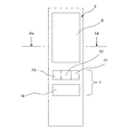
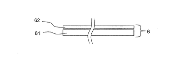
- FIG. 3 is a schematic front view of the operation panel of the cooking device. 4 is a schematic cross-sectional view taken along line F4-F4 in FIG.
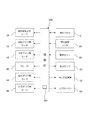
- FIG. 5 is a control block diagram of the cooking device.
- FIG. 6 is a diagram showing a top menu screen displayed on the color liquid crystal display unit.
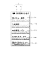
- FIG. 7 is a diagram showing a dish collection selection screen displayed on the color liquid crystal panel.
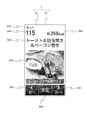
- FIG. 8 is a view showing one screen displayed on the color liquid crystal panel.
- FIG. 9 is a view showing one screen displayed on the color liquid crystal panel.
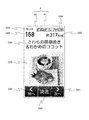
- FIG. 10 is a view showing one screen displayed on the color liquid crystal panel.
- FIG. 11 is a view showing one screen displayed on the color liquid crystal panel.
- FIG. 12 shows one screen displayed on the color liquid crystal panel.
- FIG. 13 is a diagram for explaining switching of one screen displayed on the color liquid crystal panel.
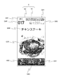
- FIG. 14 is a view showing one screen displayed on the color liquid crystal panel.
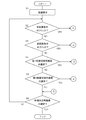
- FIG. 15A is a flowchart for explaining screen control of the control unit to the color liquid crystal panel.
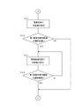
- FIG. 15B is a flowchart for explaining screen control of the control unit to the color liquid crystal panel.
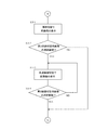
- FIG. 15C is a flowchart for explaining screen control of the control unit to the color liquid crystal panel.
- FIG. 15D is a flowchart for explaining screen control of the control unit to the color liquid crystal panel.
- FIG. 16 is a more detailed control block diagram of the cooking device.
- FIG. 1 is a front perspective view of a heating cooker according to an embodiment of the present invention.
- a door 2 is attached to the front of a rectangular parallelepiped casing 1 so as to rotate about the lower end side.
- a handle 3 is attached to the upper portion of the door 2 and a heat-resistant glass 4 is attached to the approximate center of the door 2.
- An operation panel 5 is provided on the right side of the door 2.
- the operation panel 5 includes a color liquid crystal display unit 6 and a button group 7.
- An exhaust duct 8 is provided on the upper side of the casing 1 and on the right rear side. Further, a dew receptacle 9 is detachably attached below the door 2 of the casing 1.
- FIG. 2 is a schematic diagram of a longitudinal section of the cooking device.
- the heating cooker supplies water from the water tank 11 to the steam generator 12.
- the steam generator 12 heats water from the water tank 11 to generate saturated water vapor.
- the saturated steam generated by the steam generator 12 is supplied to the heating chamber 13 side of the steam inlet 15 of the circulation unit 14 attached to the right side surface of the heating chamber 13 via a steam supply passage (not shown).
- the steam supply pipe 34 connected to the steam supply passage is attached in the vicinity of the steam inlet 15 of the circulation unit 14 so as to be parallel to the right side surface of the heating chamber 13.
- a circulation fan 18 is disposed in the circulation unit 14 so as to face the vapor suction port 15.
- the circulation fan 18 is rotationally driven by a fan motor 19.
- a steam duct 100 bent in an L shape is attached so as to cover the upper surface and the left side surface of the heating chamber 13.
- the steam duct 100 includes a first duct portion 110 fixed to the upper surface side of the heating chamber 13, a bent portion 120 that bends downward from the left side of the first duct portion 110, and a left side surface side of the heating chamber 13.
- a second duct portion 130 that is fixed and is continuous with the first duct portion 110 via the bent portion 120 is provided.
- the superheated steam generating heater 20 is accommodated in the first duct portion 110 of the steam duct 100.
- the superheated steam generation device 21 is configured by the first duct portion 110 of the steam duct 100 and the superheated steam generation heater 20. Note that the superheated steam generator may be provided separately from the steam duct.
- the right side of the first duct portion 110 of the steam duct 100 communicates with the steam supply port 22 provided at the top of the circulation unit 14.
- a plurality of first steam outlets 24 are provided on the top surface of the heating chamber 13, and the first duct portion 110 of the steam duct 100 communicates with the inside of the heating chamber 13 through the first steam outlet 24.
- the second duct portion 130 of the steam duct 100 communicates with the inside of the heating chamber 13 through a plurality of second steam outlets 25 provided on the left side surface of the heating chamber 13.
- the gap between the heating chamber 13 and the steam duct 100 is sealed with a heat resistant resin or the like.
- the heating chamber 13 and the steam duct 100 are covered with a heat insulating material except for the front opening of the heating chamber 13.
- a steam circulation path is formed by the circulation unit 14, the superheated steam generator 21, the heating chamber 13, and the connecting member that connects them. And the saturated water vapor
- a cooling fan part (not shown), an electrical component 17, and a magnetron 80 (shown in FIG. 5) are arranged on the lower side of the casing 1.
- the electrical component 17 includes a drive circuit that drives each part of the cooking device, a control circuit that controls the drive circuit, and the like.
- the microwave generated by the magnetron 80 is guided to the lower center of the heating chamber 13 by a waveguide (not shown), and is stirred upward by the rotating antenna 38 driven by the motor 37 and above the heating chamber 13.
- the object to be heated 27 is heated by being emitted.
- FIG. 3 is an enlarged schematic view of the operation panel 5 of FIG.
- the button group 7 includes a return key 71, a cancel key 72, a manual key 73, and a warm start key 74.
- the return key 71 is pressed to return the screen display of the color liquid crystal panel 61 described later to the previous screen display.
- the cancel key 72 is pressed to stop heating or cancel the operation.
- the manual key 73 is pressed when manually setting the high frequency output and the heating output. Also, the warm start key 74 is pressed to start heating.
- FIG. 4 is a schematic cross-sectional view taken along line F4-F4 of FIG.
- the color liquid crystal display unit 6 is configured by overlapping a touch panel 62 on a color liquid crystal panel 61.
- the color liquid crystal panel 61 can display characters, numbers, photographs and the like in color, and displays the type of cooking, the name of the dish, the heating time, the temperature, the photograph of the dish, and the like.
- the touch panel 62 is a capacitive touch panel made of a transparent material that changes the surface charge when the user touches it. As a result, the user can select an image displayed on the color liquid crystal panel 61 by touching the touch panel 62. When the user touches the touch panel 62 and selects a selectable image displayed on the color liquid crystal panel 61, the color of the image is changed.
- the image displayed on the color liquid crystal panel 61 has a selected color different from a non-selected color.
- the touch panel 62 may be replaced with, for example, a resistive film type, surface acoustic wave type, infrared type, or electromagnetic induction type touch panel.
- the color liquid crystal panel 61 is an example of the display unit of the present invention.
- FIG. 5 is a control block diagram of the heating cooker.
- the heating cooker includes a control unit 200 including a microcomputer and an input / output circuit in the electrical component unit 17 (shown in FIG. 2).
- the control unit 200 includes a superheated steam generation heater 20, a circulation fan motor 19, a cooling fan motor 16, a speaker 90, a supply damper motor 44, an exhaust damper motor 60, an operation panel 5, an internal temperature sensor 29, and a defroster.
- the sensor 50, the feed water pump 70, the steam generator 12, and the magnetron 80 are connected. Based on the signal from the operation panel 5 and the detection signals from the internal temperature sensor 29 and the thawing sensor 50, the control unit 200 controls the superheated steam generation heater 20, the circulation fan motor 19, the cooling fan motor 16, and the dilution fan.
- the motor 38, the air supply damper motor 44, the exhaust damper motor 60, the operation panel 5, the water supply pump 70, the steam generator 12, the magnetron 80, the speaker 90, and the like are controlled.
- the speaker 90 outputs sound in response to a user's finger touching the color liquid crystal panel 61 or the like.
- the speaker 90 is an example of a sound output unit of the present invention
- the control unit 200 is an example of a display control device of the present invention.
- the control unit 200 includes a characteristic sound output control unit 201.
- the characteristic sound output control unit 201 displays the last order image when the last order image of the plurality of images disappears.
- the speaker 90 is made to output the characteristic sound indicating that the display of is finished.
- the characteristic sound is a timbre, compared to the sound output by the speaker 90 when an image other than the last order of the plurality of images is displayed or when an image other than the last order of the plurality of images disappears. At least one of volume and output time is different.
- the control unit 200 includes a cooking recipe storage unit 202 and a heat cooking execution unit 203.
- the cooking recipe storage unit 202 stores a plurality of cooking recipes.
- a part of this cooking recipe includes category display images G31 and G32, menu number display images G41 to G45, calorie count display images G61 to G65, photo images G71 to G75, first screen switching image G81, and second screen, which will be described later.
- These include a switching image G82, a dish determination image G83, and dish name display images G91 to G95.
- the cooking / cooking execution unit 203 controls the steam generator 12, the superheated steam generation heater 20, the magnetron 80, and the like, and performs cooking corresponding to an image (for example, photographic image G71) selected on the touch panel.
- the cooking recipe storage unit 202 stores 287 photographic images similar to the photographic image G71 in addition to the photographic image G71.
- the portion of the touch panel 62 that overlaps the first screen switching image G81 and the second screen switching image G82 is an example of an instantaneous switching region.
- the superheated steam generating heater 20 shown in FIG. Is driven to rotate.
- the saturated steam supplied from the steam generator 12 to the upstream side in the vicinity of the steam suction port 15 of the circulation unit 14 enters the steam suction port 15 into the circulation unit 14 which is in a negative pressure due to the rotation of the circulation fan 18.
- a part of this superheated steam blows downward into the heating chamber 13 from a plurality of first steam outlets 24 provided on the top surface of the lower heating chamber 13. Further, another part of the superheated steam is blown out into the heating chamber 13 from the second steam outlet 25 of the heating chamber 13 through the steam duct 100.
- the superheated steam supplied into the heating chamber 13 heats the heated object 27 mounted on the net 40 on the tray 30, and then faces the steam inlet 15 of the circulation unit 14 on the right wall surface of the heating chamber 13. Then, the air is sucked into the circulation unit 14 from the suction port 28 formed in this manner. Then, the circulation of returning to the heating chamber 13 through the circulation path again is repeated.
- the superheated steam generation heater 20 is turned off and the circulation fan 18 is stopped. Then, since the circulation fan 18 is stopped, the circulation air flow is not generated in the circulation path, and the saturated steam supplied from the steam generator 12 to the upstream side in the vicinity of the steam suction port 15 of the circulation unit 14 is It is not forcibly sucked into the circulation unit 14. Thereby, the to-be-heated material 27 is steamed or warmed by the saturated water vapor that naturally flows into the heating chamber 13 by the vapor pressure.
- FIG. 6 is a view showing a top operation screen of the color liquid crystal panel 61.
- This top operation screen is a screen that is first displayed on the color liquid crystal panel 61 after a power plug (not shown) of the cooking device is inserted into an outlet.
- the images G1 to G8 are displayed on the top operation screen of the color liquid crystal panel 61.
- the image G1 is an image to be selected when warming a cold dish or the like, and includes a fried shrimp picture and a character “warming up”.
- the image G2 is an image to be selected when making a steamed food or a boiled food, and includes a picture of a pan and steamed rice and characters “steamed and boiled”.
- the image G3 is an image to be selected when searching for a desired dish from 207 kinds of dishes in the dish collection, and includes a picture of a book and characters “select from a dish collection”.
- the image G4 is an image to be selected when the milk or sake is warmed to an appropriate temperature, and includes pictures of cups and sake bottles, and “milk” and “sakekan”.
- the image G5 is an image to be selected when making the grilled and fried foods, and includes a roast chicken picture and the characters “baked and fried”.
- the image G6 is an image that should be selected when the user wants to use the health support menu, and includes a picture that gives an image of a healthy person and characters of “health support menu”.
- the image G7 is an image that should be selected when cooking a favorite dish of my home, and includes a picture of a push pin and characters of “favorite of my home”.
- the image G8 is an image to be selected when thawing frozen foods and the like, and includes a picture of a snow crystal and a character “defrost”.
- images G9 and G10 are also displayed on the top operation screen.
- the image G9 is an image that is selected when displaying a description of a simple operation method on the color liquid crystal panel 61.
- the image G10 is an image that is selected when an odor or dirt in the heating chamber 13 is anxious or sound such as a sound output from the speaker 9 is set on and off.
- the screen of the color liquid crystal panel 61 is switched from the top operation screen to the dish selection screen. That is, the color liquid crystal panel 61 displays the dish collection selection screen by the user's selection of the image G3.
- FIG. 7 is a view showing a dish collection selection screen of the color liquid crystal panel 61.
- a picture of a book and the text “Select from a dish collection” are displayed at the top of the dish collection selection screen. Thereby, the user can confirm that the screen of the color liquid crystal panel 61 is a dish collection selection screen.
- images G11 to G15 are also displayed on the dish collection selection screen.
- the image G11 includes a pictogram “No.” and characters “menu number”.
- the image G12 includes a magnifying glass picture and characters “by material”.
- the image G13 includes a picture of bread and the characters “candy / bread”.
- the image G14 includes a picture of a plate and a teacup, and characters of “set menu”.
- the image G15 includes a pictograph “All” and characters “all menus”.
- the screen in FIG. 8 enters “031”, and the screen in FIG. 9 changes to “115”.
- the screen of FIG. 10 is displayed as “166”
- the screen of FIG. 11 is input as “168”
- the screen of FIG. 12 is displayed on the liquid crystal panel 61.
- the category display images G31 and G32, the menu number display images G41 to G45, the calorie count display images G61 to G65, the photographic images G71 to G75, and the first screen switching image G81 are displayed.
- a second screen switching image G82, a dish determination image G83, and dish name display images G91 to G95 are displayed.
- the category display images G31 and G32 indicate categories that are associated in advance with dishes on the screen.
- the menu number display images G41 to G45 show menu numbers associated with the dishes on the screen in advance.
- the calorie count display images G61 to G65 indicate the calorie count previously associated with the dishes on the screen. That is, the number of calories in the calorie number display images G61 to G65 corresponds to the approximate number of calories of the dish on the screen.
- the dish name display images G91 to G95 show the names of dishes on the screen.
- the category display images G31 and G32, the menu number display images G41 to G45, and the calorie count display images G61 to G65 are examples of information of the present invention.
- the first screen switching image G81 and the second screen switching image G82 are examples of the key input unit of the present invention.
- Photo images G71 to G75 are examples of cooking images.
- the screen is instantly switched to a screen that displays a photographic image or the like corresponding to the menu number having a larger menu number.
- the screen is instantly switched to a screen displaying a photographic image or the like corresponding to the menu number having a menu number one smaller.
- the screen of the color liquid crystal panel 61 is the screen of FIG.
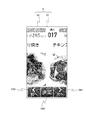
- the image on the dish determination image G83 is displayed as shown in FIG. While sliding out to the second screen switching image G82 side, the image connected to the image (the image corresponding to the menu number 017) slides in the screen from the first screen switching image G81 side.
- the screen of FIG. 14 is displayed on the color liquid crystal panel 61.
- a category display image G31, a menu number display image G46, a cooking effect display image G51, a calorie count display image G66, and a photographic image G76 are displayed as images associated with the menu number 017 in advance.
- the photographic images of the menu numbers 001 to 207 can be displayed on the color liquid crystal panel 61. It has become. If the first screen switching image G81 is selected while the screen of the color liquid crystal panel 61 is displaying the photographic image of the menu number 207, the photographic image of the menu number 001 is displayed. Here, when the photographic image with the menu number 207 disappears, the characteristic sound is output from the speaker 90. As a result, the user can easily notice that the photographic image with the menu number 207 is switched to the photographic image with the menu number 001.
- FIG. 15A to 15D are flowcharts for explaining the screen control of the control unit 200 to the color liquid crystal panel 61.
- FIG. This screen control starts when a desired menu number is input on a menu number input screen (not shown) after the user selects the image G11 on the screen of FIG.
- step S1 of FIG. 15A screen display is performed in step S1 of FIG. 15A. That is, a photographic image or the like is displayed on the color liquid crystal panel 61. This photographic image or the like corresponds to the menu number input on the menu number input screen.
- the screen of the color liquid crystal panel 61 includes at least menu number display images G41 to G45, a first screen switching image G81, and a second screen switching image G82.
- Step S1 is an example of the information display control unit of the present invention.
- step S2 it is determined whether or not there is a flick of the next image display. If it is determined in step S2 that the next image display flick has occurred, the process proceeds to step S6 described later via step S11 in FIG. 15B. On the other hand, if it is determined in step S2 that there is no flick for displaying the next image, the process proceeds to the next step S3.
- Step S11 is an example of the flick display control unit of the present invention.
- the flicking of the next image display refers to flicking a finger from the first screen switching image G81 side to the second screen switching image G82 side on the screen of the color liquid crystal panel 61.
- step S11 of FIG. 15B the next image is displayed by slide movement. More specifically, the image on the dish determination image G83 on the screen of the color liquid crystal panel 61 is slid out of the screen from the second screen switching image G82 side, and the image connected next to the image (slide out). The image corresponding to the menu number one larger than the menu number of the image) is slid into the screen from the first screen switching image G81 side.
- step S3 of FIG. 15A it is determined whether or not a previous image display flick has occurred. If it is determined in step S3 that the previous image display flick has occurred, the process proceeds to step S6 described later via step S12 in FIG. 15B. On the other hand, if it is determined in step S2 that there is no flick for displaying the previous image, the process proceeds to the next step S4.
- Step S12 is an example of the flick display control unit of the present invention.
- the flicking of the previous image display refers to flicking a finger from the second screen switching image G82 side to the first screen switching image G81 side on the screen of the color liquid crystal panel 61.
- step S12 in FIG. 15B the previous image is displayed by sliding movement. More specifically, the image on the dish determination image G83 on the screen of the color liquid crystal panel 61 is slid out of the screen from the first screen switching image G81 side, and an image connected in front of the image (slide out). The image corresponding to the menu number one smaller than the menu number of the image) is slid into the screen from the second screen switching image G82 side.
- step S4 of FIG. 15A it is determined whether or not the user's finger has touched a part of the touch panel 62 that overlaps the first screen switching image G81. That is, in step S4, it is determined whether or not the first screen switching image G81 has been selected. If it is determined in step S4 that the first screen switching image G81 has been selected, the process proceeds to step S21 in FIG. 15C. On the other hand, if it is determined in step S4 that the first screen switching image G81 is not selected, the process proceeds to the next step S5.
- step S5 it is determined whether or not the user's finger has touched a part of the touch panel 62 that overlaps the second screen switching image G82. That is, in step S5, it is determined whether or not the second screen switching image G82 has been selected. If it is determined in step S5 that the second screen switching image G82 has been selected, the process proceeds to step S31 in FIG. 15D. On the other hand, if it is determined in step S5 that the second screen switching image G82 is not selected, the process proceeds to the next step S6.
- step S6 it is determined whether or not the user's finger has touched a part of the touch panel 62 that overlaps the dish determination image G83. That is, in step S6, it is determined whether or not the dish determination image G83 has been selected. If it is determined in step S6 that the dish determination image G83 is not selected, the process returns to step S2. On the other hand, if it is determined in step S6 that the dish determination image G83 has been selected, the screen control is ended, and a state immediately before heating for cooking is started.
- step S21 the next image is displayed by image switching. More specifically, the image on the dish determination image G83 on the screen of the color liquid crystal panel 61 is changed to an image connected next to the image (an image corresponding to a menu number one larger than the menu number of the image to be erased from the screen). Switch instantly.
- step S22 it is determined whether or not the user's finger continues to touch a part of the touch panel 62 that overlaps the first screen switching image G81 for a preset time (for example, 3 seconds or 4 seconds). To do. That is, it is determined whether or not the selection of the first screen switching image G81 is continued for a preset time. If it is determined in step S22 that the selection of the first screen switching image G81 has not been continued for a preset time, the process proceeds to step S6 described above. On the other hand, if it is determined in step S22 that the selection of the first screen switching image G81 is continued for a preset time, the process proceeds to the next step S23.
- a preset time for example, 3 seconds or 4 seconds.
- step S23 the next image is displayed by high-speed image switching.
- the time required for switching images by this high-speed image switching is shorter than the time required for switching images by image switching in step S21.
- step S24 it is determined whether or not the user's finger has been removed from a part of the touch panel 62 that overlaps the first screen switching image G81. That is, in step S24, it is determined whether or not the selection of the first screen switching image G81 is released. If it is determined in step S24 that the selection of the first screen switching image G81 has not been released, the process returns to step S23. On the other hand, if it is determined in step S24 that the selection of the first screen switching image G81 has been released, the process proceeds to step S6 described above.
- steps S21 to S24 are an example of the key input display control unit of the present invention.
- Step S23 is an example of the fast switching display controller of the present invention.
- step S31 the previous image is displayed by image switching. More specifically, the image on the dish determination image G83 on the screen of the color liquid crystal panel 61 is changed to an image connected in front of the image (an image corresponding to a menu number one smaller than the menu number of the image to be erased from the screen). Switch instantly.
- step S32 it is determined whether or not the user's finger continues to touch a part of the touch panel 62 that overlaps the second screen switching image G82 for a preset time (for example, 3 seconds or 4 seconds). To do. That is, it is determined whether or not the selection of the second screen switching image G82 is continued for a preset time. If it is determined in step S32 that selection of the second screen switching image G82 has not been continued for a preset time, the process proceeds to step S6 described above. On the other hand, if it is determined in step S32 that the selection of the second screen switching image G82 is continued for a preset time, the process proceeds to the next step S33.
- a preset time for example, 3 seconds or 4 seconds.
- step S33 the previous image is displayed by high-speed image switching.
- the time required for switching images by this high-speed image switching is shorter than the time required for switching images by image switching in step S31.
- step S34 it is determined whether or not the user's finger has been released from a part of the touch panel 62 that overlaps the second screen switching image G82. That is, in step S34, it is determined whether or not the selection of the second screen switching image G82 is released. If it is determined in step S34 that the selection of the second screen switching image G82 has not been released, the process returns to step S33. On the other hand, if it is determined in step S34 that the selection of the second screen switching image G82 has been released, the process proceeds to step S6 described above.
- steps S31 to S34 are an example of the key input display controller of the present invention.
- Step S33 is an example of the fast switching display control unit of the present invention.
- the image on the dish determination image G83 on the screen of the color liquid crystal panel 61 slides out of the screen, and the next or Since the previously connected image slides in the screen, the image switching operation of the color liquid crystal panel 61 is an intuitive operation and is very simple.
- the image on the color liquid crystal panel 61 can be switched more quickly than by flick switching. Therefore, it is possible to reduce the time and burden required for displaying the target image on the color liquid crystal panel 61.
- the color liquid crystal panel 61 displays menu number display images G41 to G45 or a menu number display image similar thereto.
- the user can accurately predict the number of flick operations until the user moves from the image currently displayed on the color liquid crystal panel 61 to another target image. Therefore, the user can accurately select the flicking on the touch panel 62 and the selection of the first screen switching image G81 or the second screen switching image G82 that requires less time and burden. As a result, it is possible to reduce the time and burden required to reach the target image, but prevent the occurrence of a situation where the time and burden cannot be reduced.
- the screen control if the selection of the first screen switching image G81 or the second screen switching image G82 continues for a preset time, the screen switching speed of the color liquid crystal panel 61 increases, so that the user can It is possible to further reduce the time and burden required to reach the image.
- the photographic images of the dishes having the menu numbers 001 to 207 can be displayed on the color liquid crystal panel 61 in the order of increasing or decreasing the number of calories or in the order of the categories of the dishes. It has become.
- the touch panel 62 covers the entire color liquid crystal panel 61, but the touch panel 62 may cover only a part of the color liquid crystal panel 61, or the touch panel 62 may be a part of the color liquid crystal panel 61. You may make it not cover a part.
- the color liquid crystal panel 61 is provided on the operation panel 5.
- a color EL (electroluminescence) display unit or a monochrome display unit may be provided on the operation panel 5.
- the category display image, the menu number display image, and the calorie count display image are all displayed on the screen that displays the dish photo image.
- the category display image, the menu number display image, and the calorie count display image are displayed. Only two or one of them may be displayed.
- the first screen switching image G81 and the second screen switching image G82 are used as an example of the key input unit of the present invention.
- keys such as the return key 71 and the cancel key 72 are used in the present invention. You may use as an example of a key input part.
- flick input is performed with the user's finger, but flick input may be performed with a touch pen, for example.
- the touch pen is an example of a contact object.
- the time for which the selection of the first screen switching image G81 is further set in advance (for example, 3 seconds or 4 seconds).
- the image may be switched at a speed faster than the image switching speed in step S23.
- a step similar to steps S22 and S23 may be provided between step S23 and step S24.
- the time for which the selection of the second screen switching image G82 is further set in advance (for example, 3 seconds or 4 seconds).
- the image may be switched at a speed faster than the image switching speed in step S33.
- a step similar to steps S32 and S33 may be provided between step S33 and step S34.
- the hue when an image that can be selected on the screen of the color liquid crystal panel 61 becomes unselectable, the hue may be changed.
- the color liquid crystal panel 61 displays a photographic image of a dish with menu number 207, even if the first screen switching image G81 is pressed, the menu number 001 is displayed.
- the hue of the first screen switching image G81 when the dish photo image with the menu number 207 is displayed is a photo image other than the dish photo image with the menu number 207. You may make it differ from the hue of the 1st screen switching image G81 when is displayed. This makes it possible to visually recognize that the selection of the first screen switching image G81 is impossible.
- a part of the image on the color liquid crystal panel 61 slides out of the screen of the color liquid crystal panel 61 in response to a flick of the finger on the touch panel 62, and another image connected to the image is colored.
- a part of the image on the color liquid crystal panel 61 is displayed on the screen of the color liquid crystal panel 61 so that the pages of the book are turned according to the flick of the finger on the touch panel 62.
- another image connected to the image may be displayed on the screen of the color liquid crystal panel 61 so that the next page appears by turning the page of the book.
- the image of the display unit gradually fades out from the screen of the display unit according to the flick of the finger or pen-like object on the touch panel, and another image connected to the image is displayed on the display unit. You may gradually fade in the screen.
- the portion of the touch panel 62 that overlaps the first screen switching image G81 and the second screen switching image G82 is taken as an example of the instantaneous switching region.
- the photographic images G71, G72, G74, and G75 The portion overlapping with may be an example of the instantaneous switching region.
- a control unit that changes the speed or the number of switching images of the color liquid crystal panel 61 according to the speed at which the finger or the contact object slides may be used.
- this control unit the user can adjust the speed or number of switching of images, so that the usability of the cooking device is improved.
- Examples of the cooking device of the present invention include not only an oven range using superheated steam but also an oven using superheated steam, an oven range not using superheated steam, and an oven not using superheated steam.
- healthy cooking can be performed by using superheated steam or saturated steam in a microwave oven or the like.
- superheated steam or saturated steam having a temperature of 100 ° C. or higher is supplied to the food surface, and the superheated steam or saturated steam adhered to the food surface is condensed to give a large amount of condensation latent heat to the food. So it can efficiently transfer heat to food.
- condensed water adheres to the food surface and salt and oil are dropped together with condensed water, salt and oil in the food can be reduced.
- the inside of the heating chamber is filled with superheated steam or saturated steam to be in a low oxygen state, thereby enabling cooking while suppressing food oxidation.
- the low oxygen state refers to a state where the volume percentage of oxygen is 10% or less (for example, 0.5 to 3% or 2 to 3%) in the heating chamber.
- the display device of the present invention can be mounted on various devices such as a refrigerator, an electric rice cooker, and a machine tool.
Landscapes
- Engineering & Computer Science (AREA)
- Human Computer Interaction (AREA)
- Physics & Mathematics (AREA)
- Electromagnetism (AREA)
- Chemical & Material Sciences (AREA)
- Combustion & Propulsion (AREA)
- Mechanical Engineering (AREA)
- General Engineering & Computer Science (AREA)
- User Interface Of Digital Computer (AREA)
- Electric Ovens (AREA)
Abstract
加熱調理器は、複数の調理レシピを記憶する調理レシピ記憶部(202)と、調理レシピ記憶部(202)に記憶した調理レシピの一部を表示するカラー液晶パネル(61)と、タッチパネル(62)と、タッチパネル(62)の表面を指または接触物で触れたままスライド移動する操作により、カラー液晶パネル(61)に表示する調理レシピを逐次切り替える制御部(200)と、タッチパネル(62)で選択した調理レシピに基づき調理を実行する加熱調理実行部(203)とを備える。
Description
本発明は、加熱調理器に関すると共に、例えば加熱調理器などに使用される表示装置に関する。
従来、表示装置としては、特開2002-349858号公報(特許文献1)に記載の加熱調理器に搭載されたものがある。この表示装置は、加熱調理器のケーシングの前面に設けられた表示部と、この表示部が表示する画像を切り替えるための複数のキーとを備えている。
上記従来の表示装置によれば、ユーザは、複数のキーを操作することにより、表示部の画像を他の画像に切り替えて、所望の画像を表示部に表示させることができる。
しかしながら、上記従来の表示装置では、複数のキーの操作が必要となるため、画像の切り替えが困難になるという問題がある。
そこで、本発明の課題は、直感的な操作で表示部の画像の切り替えを簡単に行える加熱調理器および表示装置を提供することにある。
上記課題を解決するため、本発明の加熱調理器は、
複数の調理レシピを記憶する調理レシピ記憶部と、
上記調理レシピ記憶部に記憶した調理レシピの一部を表示する表示部と、
タッチパネルと、
上記タッチパネルの表面を指または接触物で触れたままスライド移動する操作により、上記表示部に表示する調理レシピを逐次切り替える表示制御装置と、
上記タッチパネルで選択した調理レシピに基づき調理を実行する加熱調理実行部と、
を備えることを特徴としている。
複数の調理レシピを記憶する調理レシピ記憶部と、
上記調理レシピ記憶部に記憶した調理レシピの一部を表示する表示部と、
タッチパネルと、
上記タッチパネルの表面を指または接触物で触れたままスライド移動する操作により、上記表示部に表示する調理レシピを逐次切り替える表示制御装置と、
上記タッチパネルで選択した調理レシピに基づき調理を実行する加熱調理実行部と、
を備えることを特徴としている。
上記構成によれば、上記表示制御装置は、タッチパネルの表面を指または接触物で触れたままスライド移動する操作により、表示部に表示する調理レシピを逐次切り替えるので、ユーザは直感的な操作で表示部の画像の切り替えを簡単に行うことができる。
また、上記調理レシピの画像は簡単に切り替えることができるので、目的の調理レシピの画像が見付け易くなる。したがって、上記画像の切り替えおよび選択を低ストレスで行うことができる。
一実施形態の加熱調理器では、
上記タッチパネルは上記表示部の少なくとも一部を覆い、
上記タッチパネルは、指または接触物がその表面に触れてスライド移動しなくても、上記表示部に表示されている調理画像を切り替えるための、瞬時切り替え領域を有する。
上記タッチパネルは上記表示部の少なくとも一部を覆い、
上記タッチパネルは、指または接触物がその表面に触れてスライド移動しなくても、上記表示部に表示されている調理画像を切り替えるための、瞬時切り替え領域を有する。
上記実施形態によれば、上記タッチパネルは、指または接触物がその表面に触れてスライド移動しなくても、表示部に表示されている調理画像を切り替えるための、瞬時切り替え領域を有するので、表示部の調理画像をてきぱき切り替えることができる。したがって、上記表示部に目的の調理画像を表示させるのにかかる時間および負担を低減できる。
一実施形態の加熱調理器では、
上記表示制御装置は、上記表示部に表示されている調理画像から他の目的とする調理画像まで移動するまでに指または接触物が上記タッチパネルの表面に触れなければならない回数を予測する目安となる情報を上記表示部が表示するように、上記表示部をさらに制御し、
上記情報は、上記表示部に表示される調理画像に予め対応付けされた番号と、上記表示部に表示される調理画像に予め対応付けされたカテゴリと、上記表示部に表示される調理画像に予め対応付けされたカロリー数とのうちの少なくとも1つである。
上記表示制御装置は、上記表示部に表示されている調理画像から他の目的とする調理画像まで移動するまでに指または接触物が上記タッチパネルの表面に触れなければならない回数を予測する目安となる情報を上記表示部が表示するように、上記表示部をさらに制御し、
上記情報は、上記表示部に表示される調理画像に予め対応付けされた番号と、上記表示部に表示される調理画像に予め対応付けされたカテゴリと、上記表示部に表示される調理画像に予め対応付けされたカロリー数とのうちの少なくとも1つである。
上記実施形態によれば、上記表示制御装置は、表示部に表示されている調理画像から他の目的とする調理画像まで移動するまでに指または接触物がタッチパネルの表面に触れなければならない回数を予測する目安となる情報を表示部が表示するように、表示部をさらに制御する。したがって、上記指または接触物をタッチパネルの表面に触れままスライド移動させる操作と、指または接触物をタッチパネルの表面に触れてスライド移動させない操作とのうち、時間および負担が少なくなる方を、ユーザが正確に選ぶことができる。
また、ユーザは、表示部に表示される情報に基づいて、表示部に表示されている調理画像から他の目的とする調理画像まで移動するまでに指または接触物がタッチパネルの表面に触れなければならない回数を予測できる。このとき、上記情報が、表示部に表示される調理画像に予め対応付けされた番号と、表示部に表示される調理画像に予め対応付けされたカテゴリと、表示部に表示される調理画像に予め対応付けされたカロリー数とのうちの少なくとも1つであるので、その予測の正確性を高めることができる。
一実施形態の加熱調理器では、
上記表示制御装置は、指または接触物が上記タッチパネルの表面に触れてスライド移動しない状態が予め設定された時間継続していると判断すると、上記表示部に表示されている調理画像を切り替える速度が上昇するように、上記表示部を制御する。
上記表示制御装置は、指または接触物が上記タッチパネルの表面に触れてスライド移動しない状態が予め設定された時間継続していると判断すると、上記表示部に表示されている調理画像を切り替える速度が上昇するように、上記表示部を制御する。
上記実施形態によれば、上記表示制御装置は、指または接触物がタッチパネルの表面に触れてスライド移動しない状態が予め設定された時間継続していると判断すると、表示部に表示されている調理画像を切り替える速度が上昇するように、表示部を制御するので、表示部に目的の調理画像を表示させるのにかかる時間および負担をさらに低減できる。
一実施形態の加熱調理器では、
上記表示制御装置は、上記表示部に表示されている調理画像を切り替える速度を上昇させた後、さらに、指または接触物が上記タッチパネルに触れてスライド移動しない状態が予め設定された時間継続していると判断すると、上記表示部に表示されている調理画像を切り替える速度がさらに上昇するように、上記表示部を制御する。
上記表示制御装置は、上記表示部に表示されている調理画像を切り替える速度を上昇させた後、さらに、指または接触物が上記タッチパネルに触れてスライド移動しない状態が予め設定された時間継続していると判断すると、上記表示部に表示されている調理画像を切り替える速度がさらに上昇するように、上記表示部を制御する。
上記実施形態によれば、上記表示制御装置は、表示部に表示されている調理画像を切り替える速度を上昇させた後、さらに、指または接触物がタッチパネルに触れてスライド移動しない状態が予め設定された時間継続していると判断すると、表示部に表示されている調理画像を切り替える速度がさらに上昇するように、表示部を制御するので、表示部に目的の調理画像を表示させるのにかかる時間および負担を低減する効果を高めることができる。
一実施形態の加熱調理器では、
上記表示制御装置は、指または接触物がスライド移動する速度に応じて、画像を切り替える速度または数を変化させる。
上記表示制御装置は、指または接触物がスライド移動する速度に応じて、画像を切り替える速度または数を変化させる。
上記実施形態によれば、上記表示制御装置は、指または接触物がスライド移動する速度に応じて、画像を切り替える速度または数を変化させるので、ユーザは画像の切り替えを速度または数を調節できる。したがって、上記加熱調理器の使い勝手を向上させることができる。
一実施形態の加熱調理器では、
ユーザの指が上記タッチパネルに触れたことに応じて音を出力する音出力部を備え、
上記表示部が複数の調理画像を予め設定された順番で繰り返し表示する場合、上記複数の調理画像の最後の順番の調理画像が消えたときに、この最後の順番の調理画像の表示が終えたことを表す特徴音を上記音出力部に出力させる特徴音出力制御部を含む。
ユーザの指が上記タッチパネルに触れたことに応じて音を出力する音出力部を備え、
上記表示部が複数の調理画像を予め設定された順番で繰り返し表示する場合、上記複数の調理画像の最後の順番の調理画像が消えたときに、この最後の順番の調理画像の表示が終えたことを表す特徴音を上記音出力部に出力させる特徴音出力制御部を含む。
上記実施形態によれば、上記特徴音出力制御部は、複数の調理画像の最後の順番の画像が消えたときに、この最後の順番の調理画像の表示が終えたことを表す特徴音を音出力部に出力させるので、ユーザは最後の順番の調理画像の表示が終わったことに容易に気付くことできる。
本発明の表示装置は、
表示部と、
上記表示部の少なくとも一部を覆うタッチパネルと、
上記表示部を制御する表示制御装置と、
上記表示部に表示されている画像を切り替えるキー入力部と
を備え、
上記表示制御装置は、
上記タッチパネルがフリック入力されると、上記表示部に表示されている画像をフリックするフリック表示制御部と、
上記キー入力部の入力に応じて、上記表示部に表示されている画像を次々切り替えるキー入力表示制御部と、
上記表示部に表示されている画像から他の目的とする画像まで移動するまでのフリック操作の回数を予測する目安となる情報を上記表示部に表示させる情報表示制御部と
を有することを特徴としている。
表示部と、
上記表示部の少なくとも一部を覆うタッチパネルと、
上記表示部を制御する表示制御装置と、
上記表示部に表示されている画像を切り替えるキー入力部と
を備え、
上記表示制御装置は、
上記タッチパネルがフリック入力されると、上記表示部に表示されている画像をフリックするフリック表示制御部と、
上記キー入力部の入力に応じて、上記表示部に表示されている画像を次々切り替えるキー入力表示制御部と、
上記表示部に表示されている画像から他の目的とする画像まで移動するまでのフリック操作の回数を予測する目安となる情報を上記表示部に表示させる情報表示制御部と
を有することを特徴としている。
ここで、「フリック入力」とは、タッチパネルの表面を例えば指またはタッチペンなどで軽く払う操作による入力を意味する。
上記構成によれば、上記表示制御装置のフリック表示制御部が、タッチパネルへのフリック入力に応じて、表示部の画像をフリックするので、直感的な操作で表示部の画像の切り替えを簡単に行うことができる。
また、上記表示制御装置のキー入力表示制御部が、キー入力部の入力に応じて、表示部の画像を次々切り替えるので、表示部の画像をてきぱき切り替えることができる。したがって、上記表示部に目的の画像を表示させるのにかかる時間および負担を低減できる。
また、上記表示制御装置の情報表示制御部が、表示部に表示されている画像から他の目的とする画像まで移動するまでのフリック操作の回数を予測する目安となる情報を表示部に表示させるので、ユーザは、タッチパネルへのフリック入力と、キー入力部への入力とのうち、時間および負担が少なくなる方を正確に選ぶことができる。
一実施形態の表示装置では、
上記キー入力表示制御部は、上記キー入力部が予め設定された時間継続して入力されていると判断すると、上記表示部に表示されている画像を切り替える速度を上昇させる高速切替表示制御部を含む。
上記キー入力表示制御部は、上記キー入力部が予め設定された時間継続して入力されていると判断すると、上記表示部に表示されている画像を切り替える速度を上昇させる高速切替表示制御部を含む。
上記実施形態によれば、上記キー入力表示制御部の高速切替表示制御部は、キー入力部が予め設定された時間継続して入力されていると判断すると、表示部に表示されている画像を切り替える速度を上昇させるので、表示部に目的の画像を表示させるのにかかる時間および負担をさらに低減できる。
一実施形態の表示装置では、
上記高速切替表示制御部が、上記表示部に表示されている画像を切り替える速度を上昇させた後、さらに、上記キー入力部が予め設定された時間継続して入力されていると判断すると、上記表示部に表示されている画像を切り替える速度をさらに上昇させる。
上記高速切替表示制御部が、上記表示部に表示されている画像を切り替える速度を上昇させた後、さらに、上記キー入力部が予め設定された時間継続して入力されていると判断すると、上記表示部に表示されている画像を切り替える速度をさらに上昇させる。
上記実施形態によれば、上記高速切替表示制御部による画像の切り替え速度の上昇があった後、さらに、ユーザが、キー入力部を予め設定された時間継続して入力することにより、画像の切り替え速度がさらに上昇するので、表示部に目的の画像を表示させるのにかかる時間および負担を低減する効果を高めることができる。
一実施形態の表示装置では、
上記情報は、上記表示部に表示される画像に予め対応付けされた番号と、上記表示部に表示される画像に予め対応付けされたカテゴリと、上記表示部に表示される画像に予め対応付けされたカロリー数とのうちの少なくとも1つである。
上記情報は、上記表示部に表示される画像に予め対応付けされた番号と、上記表示部に表示される画像に予め対応付けされたカテゴリと、上記表示部に表示される画像に予め対応付けされたカロリー数とのうちの少なくとも1つである。
上記実施形態によれば、ユーザは、表示部に表示される情報に基づいて、表示部に表示されている画像から他の目的とする画像まで移動するまでのフリック操作の回数を予測する。このとき、上記情報が、表示部に表示される画像に予め対応付けされた番号と、表示部に表示される画像に予め対応付けされたカテゴリと、表示部に表示される画像に予め対応付けされたカロリー数とのうちの少なくとも1つであるので、予測の正確性を高めることができる。
一実施形態の表示装置は、
上記キー入力部の入力に応じて音を出力する音出力部を備え、
上記表示部が複数の画像を予め設定された順番で繰り返し表示する場合、上記複数の画像の最後の順番の画像が消えたときに、この最後の順番の画像の表示が終えたことを表す特徴音を上記音出力部に出力させる特徴音出力制御部を含む。
上記キー入力部の入力に応じて音を出力する音出力部を備え、
上記表示部が複数の画像を予め設定された順番で繰り返し表示する場合、上記複数の画像の最後の順番の画像が消えたときに、この最後の順番の画像の表示が終えたことを表す特徴音を上記音出力部に出力させる特徴音出力制御部を含む。
上記実施形態によれば、上記特徴音出力制御部は、複数の画像の最後の順番の画像が消えたときに、この最後の順番の画像の表示が終えたことを表す特徴音を音出力部に出力させるので、ユーザは最後の順番の画像の表示が終わったことに容易に気付くことできる。
本発明の加熱調理器は、表示制御装置は、タッチパネルの表面を指または接触物で触れたままスライド移動する操作により、表示部に表示する調理レシピを逐次切り替えるので、ユーザは直感的な操作で表示部の画像の切り替えを簡単に行うことができる。
また、上記調理レシピの画像は簡単に切り替えることができるので、目的の調理レシピの画像が見付け易くなる。したがって、上記画像の切り替えおよび選択を低ストレスで行うことができる。
本発明の表示装置は、表示部と、この表示部を覆うタッチパネルと、その表示部を制御する表示制御装置と、その表示部に表示されている画像を切り替えるキー入力部とを備える。この表示制御装置が、タッチパネルがフリック入力されると、表示部に表示されている画像をフリックするフリック表示制御部を有するので、ユーザは直感的な操作で表示部の画像の切り替えを簡単に行うことができる。
また、上記表示制御装置が、キー入力部の入力に応じて、表示部に表示されている画像を次々切り替えるキー入力表示制御部を有するので、表示部の画像をてきぱき切り替えることができる。したがって、上記表示部に目的の画像を表示させるのにかかる時間および負担を低減できる。
また、上記表示制御装置が、表示部に表示されている画像から他の目的とする画像まで移動するまでのフリック操作の回数を予測する目安となる情報を表示部に表示させる情報表示制御部を有するので、ユーザは、タッチパネルへのフリック入力と、キー入力部への入力とのうち、時間および負担を少なくできる方を正確に選ぶことができる。
以下、本発明の加熱調理器および表示装置を図示の実施形態により詳細に説明する。
図1は本発明の一実施形態の加熱調理器の正面斜視図である。
上記加熱調理器は、直方体形状のケーシング1の正面に、下端側の辺を略中心に回動する扉2が取り付けられている。この扉2の上部にハンドル3を取り付けると共に、扉2の略中央に耐熱ガラス4を取り付けている。また、扉2の右側に操作パネル5を設けている。この操作パネル5は、カラー液晶表示部6とボタン群7を有している。また、ケーシング1の上側かつ右側後方に排気ダクト8を設けている。さらに、ケーシング1の扉2の下方に、露受容器9を着脱自在に取り付けている。
図2は上記加熱調理器の縦断面の模式図である。
上記加熱調理器は、水タンク11から蒸気発生装置12に水を供給する。蒸気発生装置12は水タンク11からの水を加熱して飽和水蒸気を生成する。蒸気発生装置12で生成された飽和水蒸気は、蒸気供給通路(図示せず)を介して、加熱庫13の右側面に取り付けられた循環ユニット14の蒸気吸込口15の加熱庫13側に供給される。
上記蒸気供給通路に接続された蒸気供給管34を、加熱庫13の右側面と平行になるように、循環ユニット14の蒸気吸込口15の近傍に取り付けている。また、循環ユニット14内には、蒸気吸込口15に対向するように循環ファン18を配置している。循環ファン18は、ファンモータ19によって回転駆動される。
上記加熱庫13の上面および左側面を覆うように、L字状に屈曲した蒸気ダクト100を取り付けている。この蒸気ダクト100は、加熱庫13の上面側に固定された第1ダクト部110と、第1ダクト部110の左側方から下側に屈曲する屈曲部120と、加熱庫13の左側面側に固定され、屈曲部120を介して第1ダクト部110に連なる第2ダクト部130とを有している。
この蒸気ダクト100の第1ダクト部110に、過熱蒸気生成ヒータ20を収納している。蒸気ダクト100の第1ダクト部110と、過熱蒸気生成ヒータ20で過熱蒸気生成装置21を構成している。なお、過熱蒸気生成装置は、蒸気ダクトとは別に設けてもよい。
そして、蒸気ダクト100の第1ダクト部110の右側は、循環ユニット14の上部に設けられた蒸気供給口22に連通している。加熱庫13の天面には、複数の第1蒸気吹出口24が設けられており、蒸気ダクト100の第1ダクト部110は、第1蒸気吹出口24を介して加熱庫13内に連通している。一方、蒸気ダクト100の第2ダクト部130は、加熱庫13の左側面に設けられた複数の第2蒸気吹出口25を介して加熱庫13内に連通している。
上記加熱庫13と蒸気ダクト100との隙間は、耐熱樹脂などによりシールされている。また、加熱庫13と蒸気ダクト100は、加熱庫13の前面開口を除いて断熱材により覆われている。
上記循環ユニット14と過熱蒸気生成装置21と加熱庫13とそれらを接続する接続部材とによって、蒸気の循環経路が形成されている。そして、この循環経路における循環ユニット14の加熱庫13との境界部に、蒸気発生装置12で生成された飽和水蒸気が供給される。
また、ケーシング1内の下側には、冷却ファン部(図示せず)と、電装部品17と、マグネトロン80(図5に示す)を配置している。電装部品17は、加熱調理器の各部を駆動する駆動回路やこの駆動回路を制御する制御回路などを有している。また、マグネトロン80で発生したマイクロ波は、導波管(図示せず)によって加熱庫13の下部中央に導かれ、モータ37によって駆動される回転アンテナ38によって攪拌されながら加熱庫13内の上方に向かって放射されて被加熱物27を加熱する。
図3は、図1の操作パネル5を拡大した概略図である。
上記ボタン群7は、戻るキー71、取り消しキー72、手動キー73およびあたためスタートキー74で構成されている。戻るキー71は、後述するカラー液晶パネル61の画面表示を直前の画面表示に戻すときに押す。また、取り消しキー72は、途中で加熱をやめるときや、操作を取り消すときに押す。そして、手動キー73は、高周波出力および加熱出力を手動で設定するときに押す。また、あたためスタートキー74は、加熱を開始するときに押す。
図4は、図3のF4-F4線から見た模式断面図である。
上記カラー液晶表示部6は、カラー液晶パネル61上にタッチパネル62を重ねて構成される。このカラー液晶パネル61は、文字、数字、写真などをカラー表示できるものであり、加熱の種類、料理名、加熱時間、温度、料理の写真などを表示する。また、タッチパネル62は、ユーザがタッチすると表面電荷を変化させる透明素材からなる静電容量方式のタッチパネルである。これにより、ユーザはタッチパネル62をタッチして、カラー液晶パネル61に表示される画像を選択できるようになっている。また、ユーザがタッチパネル62をタッチして、カラー液晶パネル61に表示される選択可能な画像を選択すると、その画像の色が変わるようになっている。つまり、カラー液晶パネル61に表示される画像は、選択状態の色が非選択状態の色と異なるようになっている。なお、タッチパネル62は、例えば、抵抗膜方式、表面弾性波方式、赤外線方式または電磁誘導方式のタッチパネルに換えてもよい。また、カラー液晶パネル61は本発明の表示部の一例である。
図5は上記加熱調理器の制御ブロック図である。
上記加熱調理器は、マイクロコンピュータと入出力回路などからなる制御部200を電装品部17(図2に示す)内に備えている。制御部200は、過熱蒸気生成ヒータ20,循環ファン用モータ19,冷却ファン用モータ16,スピーカ90,給気ダンパ用モータ44,排気ダンパ用モータ60,操作パネル5,庫内温度センサ29,解凍センサ50,給水ポンプ70,蒸気発生装置12およびマグネトロン80が接続されている。操作パネル5からの信号および庫内温度センサ29,解凍センサ50からの検出信号に基づいて、制御部200は、過熱蒸気生成ヒータ20,循環ファン用モータ19,冷却ファン用モータ16,希釈ファン用モータ38,給気ダンパ用モータ44,排気ダンパ用モータ60,操作パネル5,給水ポンプ70,蒸気発生装置12,マグネトロン80およびスピーカ90などを制御する。このスピーカ90は、カラー液晶パネル61へのユーザの指のタッチなどに応じて音を出力する。なお、スピーカ90は本発明の音出力部の一例であり、また、制御部200は本発明の表示制御装置の一例である。
また、上記制御部200は特徴音出力制御部201を含んでいる。この特徴音出力制御部201は、カラー液晶パネル61が複数の画像を予め設定された順番で繰り返し表示する場合、複数の画像の最後の順番の画像が消えたときに、この最後の順番の画像の表示が終わったことを表す特徴音をスピーカ90に出力させる。
上記特徴音は、複数の画像の最後の順番以外の画像が表されたときに、または、複数の画像の最後の順番以外の画像が消えたときにスピーカ90が出力する音に比べ、音色、音量および出力時間のうちの少なくとも1つが異なる。
より詳しく説明すると、図16に示すように、制御部200は調理レシピ記憶部202および加熱調理実行部203を含んでいる。上記調理レシピ記憶部202は、複数の調理レシピを記憶する。この調理レシピの一部が、後述するカテゴリ表示画像G31,G32、メニュー番号表示画像G41~G45、カロリー数表示画像G61~G65、写真画像G71~G75、第1画面切替用画像G81、第2画面切替用画像G82、料理決定用画像G83および料理名表示画像G91~G95などである。また、上記加熱調理実行部203は、蒸気発生装置12、過熱蒸気生成ヒータ20およびマグネトロン80などを制御して、タッチパネルで選択された画像(例えば写真画像G71)に対応する加熱調理を実行する。なお、上記調理レシピ記憶部202は、写真画像G71以外にも、写真画像G71と同様の写真画像を287個記憶している。なお、タッチパネル62において第1画面切替用画像G81,第2画面切替用画像G82に重なる部分は、瞬時切り替え領域の一例である。
上記構成の加熱調理器において、過熱蒸気(100℃を越える過熱状態にまで加熱された蒸気)によって加熱調理を行う場合には、図2に示す過熱蒸気生成ヒータ20をオンすると共に、循環ファン18を回転駆動する。そうして、蒸気発生装置12から循環ユニット14の蒸気吸込口15の近傍上流側に供給された飽和水蒸気は、循環ファン18の回転によって負圧になっている循環ユニット14内に蒸気吸込口15を介して吸い込まれて、蒸気供給口22から過熱蒸気生成装置21内に吹き出される。そして、過熱蒸気生成装置21の過熱蒸気生成ヒータ20によって加熱されて過熱蒸気となる。この過熱蒸気の一部は、下側の加熱庫13の天面に設けられた複数の第1蒸気吹出口24から、加熱庫13内に下方に向かって吹き出す。また、過熱蒸気の他の一部は、蒸気ダクト100を介して加熱庫13の第2蒸気吹出口25から加熱庫13内に吹き出す。
そして、加熱庫13内に供給された過熱蒸気は、トレイ30上の網40に搭載された被加熱物27を加熱した後、加熱庫13の右壁面に循環ユニット14の蒸気吸込口15に対向して形成された吸込口28から循環ユニット14内に吸い込まれる。そうして、再び循環経路を通って加熱庫13内に戻るという循環を繰り返す。
これに対して、非過熱蒸気によって被加熱物27を蒸すかまたは暖める運転を行う場合には、過熱蒸気生成ヒータ20をオフすると共に、循環ファン18を停止する。そうすると、循環ファン18が停止しているため、循環経路内に循環気流が発生することがなく、蒸気発生装置12から循環ユニット14の蒸気吸込口15の近傍上流側に供給された飽和水蒸気は、循環ユニット14内に強制的に吸い込まれない。これにより、蒸気圧によって自然に加熱庫13内に流れ込む飽和水蒸気により、被加熱物27を蒸すかまたは暖める。
ここで、上記加熱庫13内の左壁面および右壁面には、図2に示すように、トレイ30の両端部を係止する係止部39a,39b,39cが上下方向に3段に設けられている。そして、蒸気供給管34は、上段の係止部39aよりもやや上側に位置するように配置されている。「蒸し暖めモード」において、被加熱物27を搭載した2つのトレイ30を上段と中段とに配置する場合には、蒸気導入室36内に架設された蒸気供給管34の総てのノズル(図2の34の円形部の左側開口)を加熱庫13方向に斜め下向きにしておく。こうすることにより、被加熱物27を搭載したトレイ30が上段および中段の何れの位置にあっても、蒸気供給管34の斜め下向きのノズルから引き出された飽和水蒸気を被加熱物27に当てることができる。したがって、蒸気供給管34のノズルからの吹き出し方向を操作することなく、上中2段の被加熱物27に蒸し斑や暖め斑が生ずることがないようにできる。
図6は上記カラー液晶パネル61のトップ操作画面を示す図である。このトップ操作画面は、加熱調理器の電源プラグ(図示せず)をコンセントに差し込んだ後、カラー液晶パネル61が最初に表示する画面である。
上記カラー液晶パネル61のトップ操作画面には画像G1~G8が表示される。画像G1は、冷えた料理などを温めるときに選択すべき画像であり、エビフライの絵と、「あたためる」の文字とを含んでいる。画像G2は、蒸し物や煮物を作るときに選択すべき画像であり、鍋および蒸籠の絵と、「蒸す・煮る」の文字とを含んでいる。画像G3は、料理集内の207種類の料理から希望の料理を探すときに選択すべき画像であり、本の絵と、「お料理集から選ぶ」の文字とを含んでいる。画像G4は牛乳や酒を適温に温めるときに選択すべき画像であり、コップおよび徳利の絵と、「牛乳」および「酒のかん」の文字を含んでいる。画像G5は、焼き物およびフライ物を作るときに選択すべき画像であり、ローストチキンの絵と、「焼く・フライ」の文字とを含んでいる。画像G6は、健康サポートメニューを使いたいときに選択すべき画像であり、元気な人をイメージさせる絵と、「健康サポートメニュー」の文字とを含んでいる。画像G7は、わが家のお気に入り中の料理を作るときに選択すべき画像であり、押しピンの絵と、「わが家のお気に入り」の文字とを含んでいる。画像G8は、冷凍食材などを解凍するときに選択すべき画像であり、雪の結晶の絵と、「解凍する」の文字とを含んでいる。
また、上記トップ操作画面には画像G9,G10も表示されている。画像G9は、簡単な操作方法の説明をカラー液晶パネル61に表示させるときに選択する画像である。また、画像G10は、加熱庫13内の臭いやよごれが気になったり、スピーカ9から出力される音などのオンオフ設定をするときに選択する画像である。
上記トップ操作画面が表示されているときに、ユーザが、画像G3に重なるタッチパネル62の一部にタッチすると、カラー液晶パネル61の画面はトップ操作画面から料理集選択画面に切り換わる。つまり、ユーザの画像G3の選択により、カラー液晶パネル61が料理集選択画面を表示する。
図7は上記カラー液晶パネル61の料理集選択画面を示す図である。
上記料理集選択画面の上部には、本の絵と、「お料理集から選ぶ」の文字とが表示されている。これにより、ユーザは、カラー液晶パネル61の画面が料理集選択画面であることを確認できるようになっている。
また、上記料理集選択画面には画像G11~G15も表示される。画像G11は「No.」の絵文字と「メニュー番号」の文字とを含む。画像G12は虫眼鏡の絵と「材料別」の文字とを含む。画像G13はパンの絵と「お菓子・パン」の文字とを含む。画像G14は、皿および茶碗の絵と、「セットメニュー」の文字とを含む。画像G15は「All」の絵文字と「すべてのメニュー」の文字とを含む。
例えば、ユーザが画像G11を選択した後、図示しないメニュー番号入力画面において、「016」を入力すると、図8の画面が、「031」を入力をすると、図9の画面が、「115」を入力すると、図10の画面が、「166」を入力すると、図11の画面が、「168」を入力すると、図12の画面が、それぞれ、液晶パネル61に表示される。
図8~図12の画面では、カテゴリ表示画像G31,G32と、メニュー番号表示画像G41~G45と、カロリー数表示画像G61~G65と、写真画像G71~G75と、第1画面切替用画像G81と、第2画面切替用画像G82と、料理決定用画像G83と、料理名表示画像G91~G95とが表示される。このカテゴリ表示画像G31,G32は、画面中の料理に予め対応付けされたカテゴリを示す。また、メニュー番号表示画像G41~G45は、画面中の料理に予め対応付されているメニュー番号を示す。また、カロリー数表示画像G61~G65は、画面中の料理に予め対応付けされたカロリー数を示す。つまり、カロリー数表示画像G61~G65のカロリー数は画面中の料理のおおよそカロリー数に相当する。また、料理名表示画像G91~G95は、画面中の料理の名称を示す。なお、カテゴリ表示画像G31,G32、メニュー番号表示画像G41~G45およびカロリー数表示画像G61~G65は、本発明の情報の一例である。また、第1画面切替用画像G81および第2画面切替用画像G82は本発明のキー入力部の一例である。また、写真画像G71~G75は調理画像の一例である。
また、図8,図9,図11,図12のカラー液晶パネル61の各画面では、写真画像G71,G72,G74,G75の料理を作ることで効果が得られるので、その効果を示す調理効果表示画像G51~G54も表示される。
図8~図12の画面において、ユーザが料理決定用画像G83を選択すると、写真画像G71~G75の料理を作るための加熱が開始する直前の状態となる。
また、図8~図12の画面において、ユーザがタッチパネル62上で指をフリックすると、カラー液晶パネル61の一部の画像がカラー液晶パネル61の画面からスライドアウトすると共に、その画像に連結された他の画像がカラー液晶パネル61の画面にスライドインする。
また、図8~図12の画面において、ユーザが第1画面切替用画像G81を選択すると、メニュー番号が1つ大きいメニュー番号に対応する写真画像などを表示する画面に瞬時に切り替わる。一方、ユーザが第2画面切替用画像G82を選択すると、メニュー番号が1つ小さいメニュー番号に対応する写真画像などを表示する画面に瞬時に切り替わる。
以下、図8,図13,図14を用いて、カラー液晶パネル61の画面の一部の画像のスライドインおよびスライドアウトの一例について説明する。仮に、今、カラー液晶パネル61の画面が図8の画面だとする。ここで、カラー液晶パネル61の画面上で第1画面切替用画像G81側から第2画面切替用画像G82側に指をフリックすると、図13に示すように、料理決定用画像G83上の画像が第2画面切替用画像G82側に画面外へスライドアウトすると共に、その画像に連結された画像(メニュー番号017に対応する画像)が第1画面切替用画像G81側から画面内にスライドインして、図14の画面がカラー液晶パネル61に表示される。図14の画面では、メニュー番号017に予め対応付けされた画像としてカテゴリ表示画像G31、メニュー番号表示画像G46、調理効果表示画像G51、カロリー数表示画像G66および写真画像G76が表示される。
一方、図8の画面で第1画面切替用画像G81を選択すると、図8の画面は、図13の画面を経ずに、図14の画面に瞬時に切り替わる。
また、上記第1画面切替用画像G81もしくは第2画面切替用画像G82の選択、または、指のフリックによって、メニュー番号001からメニュー番号207までの料理の写真画像がカラー液晶パネル61に表示可能となっている。カラー液晶パネル61の画面が、メニュー番号207の写真画像を表示しているときに、第1画面切替用画像G81を選択すると、メニュー番号001の写真画像を表示する。ここで、上記メニュー番号207の写真画像が消えたときに、上記特徴音がスピーカ90から出力される。これにより、ユーザはメニュー番号207の写真画像からメニュー番号001の写真画像に切り替わったことに容易に気付くことができる。
図15A~図15Dは、上記制御部200のカラー液晶パネル61への画面制御を説明するためのフローチャートである。この画面制御は、ユーザが図7の画面において画像G11を選択した後、図示しないメニュー番号入力画面において、所望のメニュー番号が入力されることによるスタートする。
上記画面制御がスタートすると、まず、図15AのステップS1で、画面表示を行う。つまり、カラー液晶パネル61に写真画像などを表示させる。この写真画像などは、メニュー番号入力画面で入力されたメニュー番号に対応する。このとき、カラー液晶パネル61の画面は、少なくともメニュー番号表示画像G41~G45、第1画面切替用画像G81および第2画面切替用画像G82を含む。なお、ステップS1は本発明の情報表示制御部の一例である。
次に、ステップS2で、次画像表示のフリックがあったか否かを判定する。このステップS2で、上記次画像表示のフリックがあったと判定すると、図15BのステップS11を経て、後述のステップS6に進む。一方、ステップS2で、次画像表示のフリックがないと判定すると、次のステップS3に進む。なお、ステップS11は本発明のフリック表示制御部の一例である。
上記次画像表示のフリックとは、カラー液晶パネル61の画面上で第1画面切替用画像G81側から第2画面切替用画像G82側に指をフリックすることを指す。
図15BのステップS11では、スライド移動で次画像の表示を行う。より詳しくは、カラー液晶パネル61の画面における料理決定用画像G83上の画像を第2画面切替用画像G82側から画面外へスライドアウトさせると共に、その画像の次に連結された画像(スライドアウトする画像のメニュー番号より1つ大きいメニュー番号に対応する画像)を第1画面切替用画像G81側から画面内にスライドインさせる。
次に、図15AのステップS3で、前画像表示のフリックがあったか否かを判定する。このステップS3で、上記前画像表示のフリックがあったと判定すると、図15BのステップS12を経て、後述のステップS6に進む。一方、ステップS2で、前画像表示のフリックがないと判定すると、次のステップS4に進む。なお、ステップS12は本発明のフリック表示制御部の一例である。
上記前画像表示のフリックとは、カラー液晶パネル61の画面上で第2画面切替用画像G82側から第1画面切替用画像G81側に指をフリックすることを指す。
図15BのステップS12では、スライド移動で前画像の表示を行う。より詳しくは、カラー液晶パネル61の画面における料理決定用画像G83上の画像を第1画面切替用画像G81側から画面外へスライドアウトさせると共に、その画像の前に連結された画像(スライドアウトする画像のメニュー番号より1つ小さいメニュー番号に対応する画像)を第2画面切替用画像G82側から画面内にスライドインさせる。
次に、図15AのステップS4で、ユーザの指が、第1画面切替用画像G81に重なるタッチパネル62の一部にタッチしたか否かを判定する。つまり、ステップS4で、第1画面切替用画像G81が選択されたか否かを判定する。このステップS4で、第1画面切替用画像G81が選択されたと判定すると、図15CのステップS21に進む。一方、ステップS4で、第1画面切替用画像G81が選択されていないと判定すると、次のステップS5に進む。
次に、ステップS5で、ユーザの指が、第2画面切替用画像G82に重なるタッチパネル62の一部にタッチしたか否かを判定する。つまり、ステップS5で、第2画面切替用画像G82が選択されたか否かを判定する。このステップS5で、第2画面切替用画像G82が選択されたと判定すると、図15DのステップS31に進む。一方、ステップS5で、第2画面切替用画像G82が選択されていないと判定すると、次のステップS6に進む。
次に、ステップS6で、ユーザの指が、料理決定用画像G83に重なるタッチパネル62の一部にタッチしたか否かを判定する。つまり、ステップS6で、料理決定用画像G83が選択されたか否かを判定する。このステップS6で、料理決定用画像G83が選択されていないと判定すると、ステップS2に戻る。一方、ステップS6で、料理決定用画像G83が選択されたと判定すると、上記画面制御のエンドとなって、料理を作るための加熱が開始する直前の状態となる。
上記画面制御において、図15AのステップS4から図15CのステップS21に進んだ場合、まず、ステップS21で、画像切替で次画像を表示する。より詳しくは、カラー液晶パネル61の画面における料理決定用画像G83上の画像を、その画像の次に連結された画像(画面から消す画像のメニュー番号より1つ大きいメニュー番号に対応する画像)に瞬時に切り替える。
次に、ステップS22で、ユーザの指が、予め設定された時間(例えば3秒または4秒)、第1画面切替用画像G81に重なるタッチパネル62の一部にタッチし続けているか否かを判定する。つまり、予め設定された時間、第1画面切替用画像G81の選択が継続しているか否かを判定する。このステップS22で、予め設定された時間、第1画面切替用画像G81の選択が継続していないと判定すると、上述のステップS6に進む。一方、ステップS22で、予め設定された時間、第1画面切替用画像G81の選択が継続していると判定すると、次のステップS23に進む。
次に、ステップS23で、高速画像切替で次画像を表示する。この高速画像切替で画像を切り替えるのに要する時間は、ステップS21の画像切替で画像を切り替えるのに要する時間よりも短い。
次に、ステップS24で、第1画面切替用画像G81に重なるタッチパネル62の一部からユーザの指が離れたか否かを判定する。つまり、ステップS24で、第1画面切替用画像G81の選択が解除されたか否かを判定する。このステップS24で、第1画面切替用画像G81の選択が解除されていないと判断すると、ステップS23に戻る。一方、ステップS24で、第1画面切替用画像G81の選択が解除されたと判断すると、上述のステップS6に進む。ここでは、ステップS21~S24が本発明のキー入力表示制御部の一例である。また、ステップS23は本発明の高速切替表示制御部の一例である。
上記画面制御において、図15AのステップS5から図15DのステップS31に進んだ場合、まず、ステップS31で、画像切替で前画像を表示する。より詳しくは、カラー液晶パネル61の画面における料理決定用画像G83上の画像を、その画像の前に連結された画像(画面から消す画像のメニュー番号より1つ小さいメニュー番号に対応する画像)に瞬時に切り替える。
次に、ステップS32で、ユーザの指が、予め設定された時間(例えば3秒または4秒)、第2画面切替用画像G82に重なるタッチパネル62の一部にタッチし続けているか否かを判定する。つまり、予め設定された時間、第2画面切替用画像G82の選択が継続しているか否かを判定する。このステップS32で、予め設定された時間、第2画面切替用画像G82の選択が継続していないと判定すると、上述のステップS6に進む。一方、ステップS32で、予め設定された時間、第2画面切替用画像G82の選択が継続していると判定すると、次のステップS33に進む。
次に、ステップS33で、高速画像切替で前画像を表示する。この高速画像切替で画像を切り替えるのに要する時間は、ステップS31の画像切替で画像を切り替えるのに要する時間よりも短い。
次に、ステップS34で、第2画面切替用画像G82に重なるタッチパネル62の一部からユーザの指が離れたか否かを判定する。つまり、ステップS34で、第2画面切替用画像G82の選択が解除されたか否かを判定する。このステップS34で、第2画面切替用画像G82の選択が解除されていないと判断すると、ステップS33に戻る。一方、ステップS34で、第2画面切替用画像G82の選択が解除されたと判断すると、上述のステップS6に進む。ここでは、ステップS31~S34が本発明のキー入力表示制御部の一例である。また、ステップS33は本発明の高速切替表示制御部の一例である。
上述のような画面制御によって、タッチパネル62上でユーザの指がフリックするだけで、カラー液晶パネル61の画面における料理決定用画像G83上の画像が画面外へスライドアウトすると共に、その画像の次または前に連結された画像が画面内にスライドインするので、カラー液晶パネル61の画像の切り替え操作は、直感的な操作であり、非常に簡単である。
また、上記第1画面切替用画像G81または第2画面切替用画像G82を選択をすれば、フリックでの切り替えよりも、カラー液晶パネル61の画像をてきぱき切り替えることができる。したがって、カラー液晶パネル61に目的の画像を表示させるのにかかる時間および負担を低減できる。
また、上記カラー液晶パネル61は、メニュー番号表示画像G41~G45またはこれと同様のメニュー番号表示画像を表示する。これにより、ユーザは、現在、カラー液晶パネル61に表示されている画像から他の目的とする画像まで移動するまでのフリック操作の回数を精度良く予測することができる。したがって、ユーザは、タッチパネル62上でのフリックと、第1画面切替用画像G81または第2画面切替用画像G82の選択とのうち、時間および負担が少なくなる方を正確に選ぶことができる。その結果、上記目的とする画像に到達するまでにかかる時間および負担を小さくできるのに、その時間および負担を小さくできなかったという事態の発生を防ぐことができる。
また、上記画面制御において、予め設定された時間、第1画面切替用画像G81または第2画面切替用画像G82の選択が継続すると、カラー液晶パネル61の画面の切り替わり速度が上がるので、ユーザは目的とする画像に到達するまでにかかる時間および負担をさらに低減できる。
また、上記加熱調理器では、メニュー番号001からメニュー番号207までの料理の写真画像を、カロリー数の低い順もしくは高い順、または、料理のカテゴリー順にカラー液晶パネル61に表示させることもできるようになっている。
上記実施形態では、タッチパネル62がカラー液晶パネル61の全部を覆っているが、タッチパネル62がカラー液晶パネル61の一部だけを覆うようにしてもよいし、あるいは、タッチパネル62がカラー液晶パネル61の一部も覆わないようにしてもよい。
上記実施形態では、カラー液晶パネル61を操作パネル5に設けていたが、例えば、カラーEL(エレクトロルミネッセンス)表示部または白黒表示部を操作パネル5に設けてもよい。
上記実施形態において、料理の写真画像を表示する画面では、カテゴリ表示画像、メニュー番号表示画像およびカロリー数表示画像の全てを表示していたが、カテゴリ表示画像、メニュー番号表示画像およびカロリー数表示画像のうちの2つまたは1つだけを表示するようにしてもよい。
上記実施形態では、第1画面切替用画像G81および第2画面切替用画像G82を本発明のキー入力部の一例として用いていたが、戻るキー71や取り消しキー72のようなキーを本発明のキー入力部の一例として用いてもよい。
上記実施形態では、ユーザの指でフリック入力を行っていたが、例えばタッチペンでフリック入力を行うようにしてもよい。なお、上記タッチペンは接触物の一例である。
上記実施形態において、ステップS23で、高速画像切替で次画像が表示されるようになった後、さらに、第1画面切替用画像G81の選択が予め設定された時間(例えば3秒または4秒)継続したとき、ステップS23の画像の切り替え速度よりも速い速度で画像が切り替わるようにしてもよい。例えば、ステップS23とステップS24との間に、ステップS22,S23と同様のステップを設けてもよい。
上記実施形態において、ステップS33で、高速画像切替で次画像が表示されるようになった後、さらに、第2画面切替用画像G82の選択が予め設定された時間(例えば3秒または4秒)継続したとき、ステップS33の画像の切り替え速度よりも速い速度で画像が切り替わるようにしてもよい。例えば、ステップS33とステップS34との間に、ステップS32,S33と同様のステップを設けてもよい。
上記実施形態において、カラー液晶パネル61の画面において選択可能であった画像が選択不可能になったとき、色合いを変化させてもよい。例えば、図15A~図15Dのフローチャートの画面制御において、カラー液晶パネル61がメニュー番号207の料理の写真画像を表示しているときに、第1画面切替用画像G81を押しても、メニュー番号001の料理の写真画像が表示されないようにした場合、メニュー番号207の料理の写真画像が表示されているときの第1画面切替用画像G81の色合いが、メニュー番号207の料理の写真画像以外の写真画像が表示されているときの第1画面切替用画像G81の色合いと異なるようにしてもよい。これにより、第1画面切替用画像G81の選択が不可能であることを視覚的に判るようになる。
上記実施形態では、タッチパネル62上での指のフリックに応じて、カラー液晶パネル61の一部の画像がカラー液晶パネル61の画面からスライドアウトすると共に、その画像に連結された他の画像がカラー液晶パネル61の画面にスライドインしていたが、タッチパネル62上での指のフリックに応じて、本のページがめくられるように、カラー液晶パネル61の一部の画像をカラー液晶パネル61の画面外に移動させると共に、本のページをめくって次のページが現れるように、その画像に連結された他の画像をカラー液晶パネル61の画面に表示するようにしてもよい。
要するに、本発明では、タッチパネル上での指またはペン状物体のフリックに応じて、表示部の画像が表示部の画面から徐々にフェードアウトすると共に、その画像に連結された他の画像が表示部の画面に徐々にフェードインするようしてもよい。
上記実施形態では、タッチパネル62において第1画面切替用画像G81,第2画面切替用画像G82に重なる部分を、瞬時切替領域の一例にしていたが、タッチパネル62において写真画像G71,G72,G74,G75に重なる部分を、瞬時切り替え領域の一例にしてもよい。
上記実施形態の制御部200に換えて、指または接触物がスライド移動する速度に応じて、カラー液晶パネル61の画像を切り替える速度または数を変化させる制御部を用いてもよい。この制御部を用いた場合、ユーザは画像の切り替えを速度または数を調節できるので、加熱調理器の使い勝手が良好になる。
本発明の加熱調理器としては、例えば、過熱水蒸気を使用するオーブンレンジのみならず、過熱水蒸気を使用するオーブン、過熱水蒸気を使用しないオーブンレンジ、過熱水蒸気を使用しないオーブンなどがある。
本発明の加熱調理器では、オーブンレンジなどにおいて、過熱水蒸気または飽和水蒸気を用いることによって、ヘルシーな調理を行うことができる。例えば、本発明の加熱調理器では、温度が100℃以上の過熱水蒸気または飽和水蒸気を食品表面に供給し、食品表面に付着した過熱水蒸気または飽和水蒸気が凝縮して大量の凝縮潜熱を食品に与えるので、食品に熱を効率よく伝えることができる。また、凝縮水が食品表面に付着して塩分や油分が凝縮水と共に滴下することにより、食品中の塩分や油分を低減できる。さらに、加熱庫内は過熱水蒸気または飽和水蒸気が充満して低酸素状態となることにより、食品の酸化を抑制した調理が可能となる。ここで、低酸素状態とは、加熱室内において酸素の体積%が10%以下(例えば0.5~3%または2~3%)である状態を指す。
本発明の具体的な実施形態について説明したが、本発明は上記実施形態に限定されるものではなく、本発明の範囲内で種々変更して実施することができる。例えば、本発明の表示装置は、例えば、冷蔵庫、電気炊飯器、工作機械などいった様々な機器に搭載できる。
1…ケーシング
2…扉
3…ハンドル
4…耐熱ガラス
5…操作パネル
6…カラー液晶表示部
7…ボタン群
8…排気ダクト
9…露受容器
11…水タンク
12…蒸気発生装置
13…加熱庫
14…循環ユニット
15…蒸気吸込口
17…電装部品
18…循環ファン
19…ファンモータ
20…過熱蒸気生成ヒータ
21…過熱蒸気生成装置
22…蒸気供給口
24…第1蒸気吹出口
25…第2蒸気吹出口
27…被加熱物
28…吸込口
30…トレイ
34…蒸気供給管
36…蒸気導入室
37…モータ
38…回転アンテナ
39a,39b,39c…係止部
40…網
61…カラー液晶パネル
62…タッチパネル
90…スピーカ
100…蒸気ダクト
110…第1ダクト部
120…屈曲部
130…第2ダクト部
200…制御部
201…音出力制御部
202…調理レシピ記憶部
203…加熱調理実行部
G31,G32…カテゴリ表示画像
G41~G45…メニュー番号表示画像
G61~G65…カロリー数表示画像
G81…第1画面切替用画像
G82…第2画面切替用画像
2…扉
3…ハンドル
4…耐熱ガラス
5…操作パネル
6…カラー液晶表示部
7…ボタン群
8…排気ダクト
9…露受容器
11…水タンク
12…蒸気発生装置
13…加熱庫
14…循環ユニット
15…蒸気吸込口
17…電装部品
18…循環ファン
19…ファンモータ
20…過熱蒸気生成ヒータ
21…過熱蒸気生成装置
22…蒸気供給口
24…第1蒸気吹出口
25…第2蒸気吹出口
27…被加熱物
28…吸込口
30…トレイ
34…蒸気供給管
36…蒸気導入室
37…モータ
38…回転アンテナ
39a,39b,39c…係止部
40…網
61…カラー液晶パネル
62…タッチパネル
90…スピーカ
100…蒸気ダクト
110…第1ダクト部
120…屈曲部
130…第2ダクト部
200…制御部
201…音出力制御部
202…調理レシピ記憶部
203…加熱調理実行部
G31,G32…カテゴリ表示画像
G41~G45…メニュー番号表示画像
G61~G65…カロリー数表示画像
G81…第1画面切替用画像
G82…第2画面切替用画像
Claims (8)
- 複数の調理レシピを記憶する調理レシピ記憶部(202)と、
上記調理レシピ記憶部(202)に記憶した調理レシピの一部を表示する表示部(61)と、
タッチパネル(62)と、
上記タッチパネル(62)の表面を指または接触物で触れたままスライド移動する操作により、上記表示部(61)に表示する調理レシピを逐次切り替える表示制御装置(200)と、
上記タッチパネル(62)で選択した調理レシピに基づき調理を実行する加熱調理実行部(203)と、
を備えることを特徴とする加熱調理器。 - 請求項1に記載の加熱調理器において、
上記タッチパネル(62)は上記表示部(61)の少なくとも一部を覆い、
上記タッチパネル(62)は、指または接触物がその表面に触れてスライド移動しなくても、上記表示部(61)に表示されている調理画像(G71~G76)を切り替えるための、瞬時切り替え領域を有することを特徴とする加熱調理器。 - 請求項2に記載の加熱調理器において、
上記表示制御装置(200)は、上記表示部(61)に表示されている調理画像(G71~G76)から他の目的とする調理画像(G71~G76)まで移動するまでに指または接触物が上記タッチパネル(62)の表面に触れなければならない回数を予測する目安となる情報(G31,G32,G41~G46,G61~G66)を上記表示部(61)が表示するように、上記表示部(61)をさらに制御し、
上記情報(G31,G32,G41~G46,G61~G66)は、上記表示部(61)に表示される調理画像(G71~G76)に予め対応付けされた番号と、上記表示部(61)に表示される調理画像(G71~G76)に予め対応付けされたカテゴリと、上記表示部(61)に表示される調理画像(G71~G76)に予め対応付けされたカロリー数とのうちの少なくとも1つであることを特徴とする加熱調理器。 - 請求項2または3に記載の加熱調理器において、
上記表示制御装置(200)は、指または接触物が上記タッチパネル(62)の表面に触れてスライド移動しない状態が予め設定された時間継続していると判断すると、上記表示部(61)に表示されている調理画像(G71~G76)を切り替える速度が上昇するように、上記表示部(61)を制御することを特徴とする加熱調理器。 - 請求項4に記載の加熱調理器において、
上記表示制御装置(200)は、上記表示部(61)に表示されている調理画像(G71~G76)を切り替える速度を上昇させた後、さらに、指または接触物が上記タッチパネル(62)に触れてスライド移動しない状態が予め設定された時間継続していると判断すると、上記表示部(61)に表示されている調理画像(G71~G76)を切り替える速度がさらに上昇するように、上記表示部(61)を制御することを特徴とする加熱調理器。 - 請求項1から5までのいずれか一項に記載の加熱調理器において、
上記表示制御装置(200)は、指または接触物がスライド移動する速度に応じて、画像(G71~G76)を切り替える速度または数を変化させることを特徴とする加熱調理器。 - 請求項1から6までのいずれか一項に記載の加熱調理器において、
ユーザの指が上記タッチパネル(62)に触れたことに応じて音を出力する音出力部(90)を備え、
上記表示部(61)が複数の調理画像(G71~G76)を予め設定された順番で繰り返し表示する場合、上記複数の調理画像(G71~G76)の最後の順番の調理画像(G71~G76)が消えたときに、この最後の順番の調理画像(G71~G76)の表示が終えたことを表す特徴音を上記音出力部(90)に出力させる特徴音出力制御部(201)を含むことを特徴とする加熱調理器。 - 表示部(61)と、
上記表示部(61)の少なくとも一部を覆うタッチパネル(62)と、
上記表示部(61)を制御する表示制御装置(200)と、
上記表示部(61)に表示されている画像(G71~G76)を切り替えるキー入力部(G81,G82)と
を備え、
上記表示制御装置(200)は、
上記タッチパネル(62)がフリック入力されると、上記表示部(61)に表示されている画像(G71~G76)をフリックするフリック表示制御部(S11)と、
上記キー入力部(G81,G82)の入力に応じて、上記表示部(61)に表示されている画像(G71~G76)を次々切り替えるキー入力表示制御部(S21~S24)と、
上記表示部(61)に表示されている画像(G71~G76)から他の目的とする画像(G71~G76)まで移動するまでのフリック操作の回数を予測する目安となる情報(G31,G32,G41~G46,G61~G66)を上記表示部(61)に表示させる情報表示制御部(S1)と
を有することを特徴とする表示装置。
Priority Applications (1)
| Application Number | Priority Date | Filing Date | Title |
|---|---|---|---|
| CN201180033463.2A CN102985760B (zh) | 2010-07-14 | 2011-07-13 | 加热烹调器和显示装置 |
Applications Claiming Priority (4)
| Application Number | Priority Date | Filing Date | Title |
|---|---|---|---|
| JP2010159997 | 2010-07-14 | ||
| JP2010-159997 | 2010-07-14 | ||
| JP2011104462A JP4932043B2 (ja) | 2010-07-14 | 2011-05-09 | 加熱調理器 |
| JP2011-104462 | 2011-05-09 |
Publications (1)
| Publication Number | Publication Date |
|---|---|
| WO2012008481A1 true WO2012008481A1 (ja) | 2012-01-19 |
Family
ID=45469478
Family Applications (1)
| Application Number | Title | Priority Date | Filing Date |
|---|---|---|---|
| PCT/JP2011/065953 Ceased WO2012008481A1 (ja) | 2010-07-14 | 2011-07-13 | 加熱調理器および表示装置 |
Country Status (3)
| Country | Link |
|---|---|
| JP (1) | JP4932043B2 (ja) |
| CN (1) | CN102985760B (ja) |
| WO (1) | WO2012008481A1 (ja) |
Cited By (2)
| Publication number | Priority date | Publication date | Assignee | Title |
|---|---|---|---|---|
| WO2016162766A1 (de) * | 2015-04-09 | 2016-10-13 | BSH Hausgeräte GmbH | Kochfeldvorrichtung |
| US10222964B2 (en) | 2013-10-21 | 2019-03-05 | Panasonic Ip Management Co., Ltd. | Operation device and operation method |
Families Citing this family (8)
| Publication number | Priority date | Publication date | Assignee | Title |
|---|---|---|---|---|
| EP2938160B1 (en) | 2012-12-20 | 2017-03-15 | Panasonic Intellectual Property Management Co., Ltd. | Cooker |
| JP2015041328A (ja) * | 2013-08-23 | 2015-03-02 | 三菱電機株式会社 | 加熱調理器 |
| CN104287639B (zh) * | 2014-10-30 | 2016-10-26 | 广东美的厨房电器制造有限公司 | 蒸汽烤箱 |
| CN105595792A (zh) * | 2015-11-23 | 2016-05-25 | 日升五金制品(深圳)有限公司 | 可移除温控部件的电加热烹调容器及其加热恒温控制方法 |
| JP6506861B2 (ja) * | 2018-02-21 | 2019-04-24 | シャープ株式会社 | 加熱調理器 |
| JP2021167689A (ja) * | 2020-04-10 | 2021-10-21 | 東芝ホームテクノ株式会社 | 加熱調理器 |
| JP7579133B2 (ja) * | 2020-12-23 | 2024-11-07 | 東芝ホームテクノ株式会社 | 加熱調理器 |
| JP7702593B2 (ja) * | 2021-07-06 | 2025-07-04 | パナソニックIpマネジメント株式会社 | レシピ提供方法、加熱調理器、レシピ提供プログラム、及びレシピ提供システム |
Citations (2)
| Publication number | Priority date | Publication date | Assignee | Title |
|---|---|---|---|---|
| JP2002349858A (ja) * | 2001-05-28 | 2002-12-04 | Matsushita Electric Ind Co Ltd | 加熱調理器 |
| JP2010009104A (ja) * | 2008-06-24 | 2010-01-14 | Suijinsha:Kk | 電子書籍ビューワ |
Family Cites Families (3)
| Publication number | Priority date | Publication date | Assignee | Title |
|---|---|---|---|---|
| KR100476451B1 (ko) * | 2002-02-14 | 2005-03-17 | 엘지전자 주식회사 | 전자레인지의 메뉴선택장치 |
| DE202004000087U1 (de) * | 2004-01-07 | 2004-03-18 | Rational Ag | Bedienleiste für ein Gargerät |
| JP2011033870A (ja) * | 2009-08-03 | 2011-02-17 | Sony Corp | 画像処理装置、画像処理方法およびプログラム |
-
2011
- 2011-05-09 JP JP2011104462A patent/JP4932043B2/ja not_active Expired - Fee Related
- 2011-07-13 WO PCT/JP2011/065953 patent/WO2012008481A1/ja not_active Ceased
- 2011-07-13 CN CN201180033463.2A patent/CN102985760B/zh not_active Expired - Fee Related
Patent Citations (2)
| Publication number | Priority date | Publication date | Assignee | Title |
|---|---|---|---|---|
| JP2002349858A (ja) * | 2001-05-28 | 2002-12-04 | Matsushita Electric Ind Co Ltd | 加熱調理器 |
| JP2010009104A (ja) * | 2008-06-24 | 2010-01-14 | Suijinsha:Kk | 電子書籍ビューワ |
Cited By (2)
| Publication number | Priority date | Publication date | Assignee | Title |
|---|---|---|---|---|
| US10222964B2 (en) | 2013-10-21 | 2019-03-05 | Panasonic Ip Management Co., Ltd. | Operation device and operation method |
| WO2016162766A1 (de) * | 2015-04-09 | 2016-10-13 | BSH Hausgeräte GmbH | Kochfeldvorrichtung |
Also Published As
| Publication number | Publication date |
|---|---|
| CN102985760A (zh) | 2013-03-20 |
| JP4932043B2 (ja) | 2012-05-16 |
| JP2012037219A (ja) | 2012-02-23 |
| CN102985760B (zh) | 2015-07-15 |
Similar Documents
| Publication | Publication Date | Title |
|---|---|---|
| JP4932043B2 (ja) | 加熱調理器 | |
| JP5351337B2 (ja) | 表示装置および加熱調理器 | |
| WO2015004941A1 (ja) | 加熱調理器 | |
| JP5823675B2 (ja) | 加熱調理器 | |
| JP6006996B2 (ja) | 表示装置および加熱調理器 | |
| JP5869159B2 (ja) | 電気機器 | |
| JP2012021705A (ja) | 加熱調理器 | |
| JP5932560B2 (ja) | 加熱調理器 | |
| JP2014222141A (ja) | 加熱調理器 | |
| JP6113898B2 (ja) | 加熱調理器 | |
| JP5901163B2 (ja) | 加熱調理器 | |
| JP6163231B2 (ja) | 加熱調理器 | |
| JP6043416B2 (ja) | 加熱調理器 | |
| JP5936944B2 (ja) | 加熱調理器 | |
| JP6576971B2 (ja) | 表示装置および加熱調理器 | |
| JP5707450B2 (ja) | 加熱調理器 | |
| JP2013019577A (ja) | 加熱調理器 | |
| JP5574879B2 (ja) | 加熱調理器 | |
| JP5690673B2 (ja) | 画像入力装置、家電機器および加熱調理器 | |
| JP5785806B2 (ja) | 加熱調理器 | |
| JP2012042100A (ja) | 加熱調理器 | |
| JP5805142B2 (ja) | 加熱調理器 | |
| JP5899337B2 (ja) | 加熱調理器 | |
| JP2016075472A (ja) | 電気機器 | |
| JP2017015394A (ja) | 加熱調理器 |
Legal Events
| Date | Code | Title | Description |
|---|---|---|---|
| WWE | Wipo information: entry into national phase |
Ref document number: 201180033463.2 Country of ref document: CN |
|
| 121 | Ep: the epo has been informed by wipo that ep was designated in this application |
Ref document number: 11806811 Country of ref document: EP Kind code of ref document: A1 |
|
| NENP | Non-entry into the national phase |
Ref country code: DE |
|
| 122 | Ep: pct application non-entry in european phase |
Ref document number: 11806811 Country of ref document: EP Kind code of ref document: A1 |