WO2012007989A1 - 燃料電池用配管ユニットおよびそれを備えた燃料電池ユニット、燃料電池システム - Google Patents
燃料電池用配管ユニットおよびそれを備えた燃料電池ユニット、燃料電池システム Download PDFInfo
- Publication number
- WO2012007989A1 WO2012007989A1 PCT/JP2010/004550 JP2010004550W WO2012007989A1 WO 2012007989 A1 WO2012007989 A1 WO 2012007989A1 JP 2010004550 W JP2010004550 W JP 2010004550W WO 2012007989 A1 WO2012007989 A1 WO 2012007989A1
- Authority
- WO
- WIPO (PCT)
- Prior art keywords
- cathode
- fuel cell
- pipe
- gas
- valve
- Prior art date
- Legal status (The legal status is an assumption and is not a legal conclusion. Google has not performed a legal analysis and makes no representation as to the accuracy of the status listed.)
- Ceased
Links
Images













Classifications
-
- H—ELECTRICITY
- H01—ELECTRIC ELEMENTS
- H01M—PROCESSES OR MEANS, e.g. BATTERIES, FOR THE DIRECT CONVERSION OF CHEMICAL ENERGY INTO ELECTRICAL ENERGY
- H01M8/00—Fuel cells; Manufacture thereof
- H01M8/04—Auxiliary arrangements, e.g. for control of pressure or for circulation of fluids
- H01M8/04082—Arrangements for control of reactant parameters, e.g. pressure or concentration
- H01M8/04201—Reactant storage and supply, e.g. means for feeding, pipes
-
- H—ELECTRICITY
- H01—ELECTRIC ELEMENTS
- H01M—PROCESSES OR MEANS, e.g. BATTERIES, FOR THE DIRECT CONVERSION OF CHEMICAL ENERGY INTO ELECTRICAL ENERGY
- H01M8/00—Fuel cells; Manufacture thereof
- H01M8/04—Auxiliary arrangements, e.g. for control of pressure or for circulation of fluids
- H01M8/04082—Arrangements for control of reactant parameters, e.g. pressure or concentration
- H01M8/04089—Arrangements for control of reactant parameters, e.g. pressure or concentration of gaseous reactants
- H01M8/04119—Arrangements for control of reactant parameters, e.g. pressure or concentration of gaseous reactants with simultaneous supply or evacuation of electrolyte; Humidifying or dehumidifying
- H01M8/04156—Arrangements for control of reactant parameters, e.g. pressure or concentration of gaseous reactants with simultaneous supply or evacuation of electrolyte; Humidifying or dehumidifying with product water removal
- H01M8/04164—Arrangements for control of reactant parameters, e.g. pressure or concentration of gaseous reactants with simultaneous supply or evacuation of electrolyte; Humidifying or dehumidifying with product water removal by condensers, gas-liquid separators or filters
-
- H—ELECTRICITY
- H01—ELECTRIC ELEMENTS
- H01M—PROCESSES OR MEANS, e.g. BATTERIES, FOR THE DIRECT CONVERSION OF CHEMICAL ENERGY INTO ELECTRICAL ENERGY
- H01M8/00—Fuel cells; Manufacture thereof
- H01M8/04—Auxiliary arrangements, e.g. for control of pressure or for circulation of fluids
- H01M8/04223—Auxiliary arrangements, e.g. for control of pressure or for circulation of fluids during start-up or shut-down; Depolarisation or activation, e.g. purging; Means for short-circuiting defective fuel cells
-
- H—ELECTRICITY
- H01—ELECTRIC ELEMENTS
- H01M—PROCESSES OR MEANS, e.g. BATTERIES, FOR THE DIRECT CONVERSION OF CHEMICAL ENERGY INTO ELECTRICAL ENERGY
- H01M8/00—Fuel cells; Manufacture thereof
- H01M8/04—Auxiliary arrangements, e.g. for control of pressure or for circulation of fluids
- H01M8/04223—Auxiliary arrangements, e.g. for control of pressure or for circulation of fluids during start-up or shut-down; Depolarisation or activation, e.g. purging; Means for short-circuiting defective fuel cells
- H01M8/04225—Auxiliary arrangements, e.g. for control of pressure or for circulation of fluids during start-up or shut-down; Depolarisation or activation, e.g. purging; Means for short-circuiting defective fuel cells during start-up
-
- H—ELECTRICITY
- H01—ELECTRIC ELEMENTS
- H01M—PROCESSES OR MEANS, e.g. BATTERIES, FOR THE DIRECT CONVERSION OF CHEMICAL ENERGY INTO ELECTRICAL ENERGY
- H01M8/00—Fuel cells; Manufacture thereof
- H01M8/04—Auxiliary arrangements, e.g. for control of pressure or for circulation of fluids
- H01M8/04223—Auxiliary arrangements, e.g. for control of pressure or for circulation of fluids during start-up or shut-down; Depolarisation or activation, e.g. purging; Means for short-circuiting defective fuel cells
- H01M8/04228—Auxiliary arrangements, e.g. for control of pressure or for circulation of fluids during start-up or shut-down; Depolarisation or activation, e.g. purging; Means for short-circuiting defective fuel cells during shut-down
-
- H—ELECTRICITY
- H01—ELECTRIC ELEMENTS
- H01M—PROCESSES OR MEANS, e.g. BATTERIES, FOR THE DIRECT CONVERSION OF CHEMICAL ENERGY INTO ELECTRICAL ENERGY
- H01M8/00—Fuel cells; Manufacture thereof
- H01M8/04—Auxiliary arrangements, e.g. for control of pressure or for circulation of fluids
- H01M8/04298—Processes for controlling fuel cells or fuel cell systems
- H01M8/043—Processes for controlling fuel cells or fuel cell systems applied during specific periods
- H01M8/04303—Processes for controlling fuel cells or fuel cell systems applied during specific periods applied during shut-down
-
- H—ELECTRICITY
- H01—ELECTRIC ELEMENTS
- H01M—PROCESSES OR MEANS, e.g. BATTERIES, FOR THE DIRECT CONVERSION OF CHEMICAL ENERGY INTO ELECTRICAL ENERGY
- H01M8/00—Fuel cells; Manufacture thereof
- H01M8/04—Auxiliary arrangements, e.g. for control of pressure or for circulation of fluids
- H01M8/04298—Processes for controlling fuel cells or fuel cell systems
- H01M8/04694—Processes for controlling fuel cells or fuel cell systems characterised by variables to be controlled
- H01M8/04746—Pressure; Flow
- H01M8/04753—Pressure; Flow of fuel cell reactants
-
- H—ELECTRICITY
- H01—ELECTRIC ELEMENTS
- H01M—PROCESSES OR MEANS, e.g. BATTERIES, FOR THE DIRECT CONVERSION OF CHEMICAL ENERGY INTO ELECTRICAL ENERGY
- H01M8/00—Fuel cells; Manufacture thereof
- H01M8/04—Auxiliary arrangements, e.g. for control of pressure or for circulation of fluids
- H01M8/04298—Processes for controlling fuel cells or fuel cell systems
- H01M8/04694—Processes for controlling fuel cells or fuel cell systems characterised by variables to be controlled
- H01M8/04746—Pressure; Flow
- H01M8/04761—Pressure; Flow of fuel cell exhausts
-
- H—ELECTRICITY
- H01—ELECTRIC ELEMENTS
- H01M—PROCESSES OR MEANS, e.g. BATTERIES, FOR THE DIRECT CONVERSION OF CHEMICAL ENERGY INTO ELECTRICAL ENERGY
- H01M8/00—Fuel cells; Manufacture thereof
- H01M8/24—Grouping of fuel cells, e.g. stacking of fuel cells
- H01M8/2465—Details of groupings of fuel cells
- H01M8/2483—Details of groupings of fuel cells characterised by internal manifolds
-
- H—ELECTRICITY
- H01—ELECTRIC ELEMENTS
- H01M—PROCESSES OR MEANS, e.g. BATTERIES, FOR THE DIRECT CONVERSION OF CHEMICAL ENERGY INTO ELECTRICAL ENERGY
- H01M8/00—Fuel cells; Manufacture thereof
- H01M8/24—Grouping of fuel cells, e.g. stacking of fuel cells
- H01M8/2465—Details of groupings of fuel cells
- H01M8/2484—Details of groupings of fuel cells characterised by external manifolds
-
- H—ELECTRICITY
- H01—ELECTRIC ELEMENTS
- H01M—PROCESSES OR MEANS, e.g. BATTERIES, FOR THE DIRECT CONVERSION OF CHEMICAL ENERGY INTO ELECTRICAL ENERGY
- H01M8/00—Fuel cells; Manufacture thereof
- H01M8/10—Fuel cells with solid electrolytes
- H01M2008/1095—Fuel cells with polymeric electrolytes
-
- H—ELECTRICITY
- H01—ELECTRIC ELEMENTS
- H01M—PROCESSES OR MEANS, e.g. BATTERIES, FOR THE DIRECT CONVERSION OF CHEMICAL ENERGY INTO ELECTRICAL ENERGY
- H01M8/00—Fuel cells; Manufacture thereof
- H01M8/04—Auxiliary arrangements, e.g. for control of pressure or for circulation of fluids
- H01M8/04007—Auxiliary arrangements, e.g. for control of pressure or for circulation of fluids related to heat exchange
-
- H—ELECTRICITY
- H01—ELECTRIC ELEMENTS
- H01M—PROCESSES OR MEANS, e.g. BATTERIES, FOR THE DIRECT CONVERSION OF CHEMICAL ENERGY INTO ELECTRICAL ENERGY
- H01M8/00—Fuel cells; Manufacture thereof
- H01M8/04—Auxiliary arrangements, e.g. for control of pressure or for circulation of fluids
- H01M8/04082—Arrangements for control of reactant parameters, e.g. pressure or concentration
- H01M8/04089—Arrangements for control of reactant parameters, e.g. pressure or concentration of gaseous reactants
- H01M8/04097—Arrangements for control of reactant parameters, e.g. pressure or concentration of gaseous reactants with recycling of the reactants
-
- H—ELECTRICITY
- H01—ELECTRIC ELEMENTS
- H01M—PROCESSES OR MEANS, e.g. BATTERIES, FOR THE DIRECT CONVERSION OF CHEMICAL ENERGY INTO ELECTRICAL ENERGY
- H01M8/00—Fuel cells; Manufacture thereof
- H01M8/04—Auxiliary arrangements, e.g. for control of pressure or for circulation of fluids
- H01M8/04082—Arrangements for control of reactant parameters, e.g. pressure or concentration
- H01M8/04089—Arrangements for control of reactant parameters, e.g. pressure or concentration of gaseous reactants
- H01M8/04119—Arrangements for control of reactant parameters, e.g. pressure or concentration of gaseous reactants with simultaneous supply or evacuation of electrolyte; Humidifying or dehumidifying
- H01M8/04126—Humidifying
- H01M8/04141—Humidifying by water containing exhaust gases
-
- H—ELECTRICITY
- H01—ELECTRIC ELEMENTS
- H01M—PROCESSES OR MEANS, e.g. BATTERIES, FOR THE DIRECT CONVERSION OF CHEMICAL ENERGY INTO ELECTRICAL ENERGY
- H01M8/00—Fuel cells; Manufacture thereof
- H01M8/04—Auxiliary arrangements, e.g. for control of pressure or for circulation of fluids
- H01M8/04223—Auxiliary arrangements, e.g. for control of pressure or for circulation of fluids during start-up or shut-down; Depolarisation or activation, e.g. purging; Means for short-circuiting defective fuel cells
- H01M8/04253—Means for solving freezing problems
-
- Y—GENERAL TAGGING OF NEW TECHNOLOGICAL DEVELOPMENTS; GENERAL TAGGING OF CROSS-SECTIONAL TECHNOLOGIES SPANNING OVER SEVERAL SECTIONS OF THE IPC; TECHNICAL SUBJECTS COVERED BY FORMER USPC CROSS-REFERENCE ART COLLECTIONS [XRACs] AND DIGESTS
- Y02—TECHNOLOGIES OR APPLICATIONS FOR MITIGATION OR ADAPTATION AGAINST CLIMATE CHANGE
- Y02E—REDUCTION OF GREENHOUSE GAS [GHG] EMISSIONS, RELATED TO ENERGY GENERATION, TRANSMISSION OR DISTRIBUTION
- Y02E60/00—Enabling technologies; Technologies with a potential or indirect contribution to GHG emissions mitigation
- Y02E60/30—Hydrogen technology
- Y02E60/50—Fuel cells
-
- Y—GENERAL TAGGING OF NEW TECHNOLOGICAL DEVELOPMENTS; GENERAL TAGGING OF CROSS-SECTIONAL TECHNOLOGIES SPANNING OVER SEVERAL SECTIONS OF THE IPC; TECHNICAL SUBJECTS COVERED BY FORMER USPC CROSS-REFERENCE ART COLLECTIONS [XRACs] AND DIGESTS
- Y10—TECHNICAL SUBJECTS COVERED BY FORMER USPC
- Y10T—TECHNICAL SUBJECTS COVERED BY FORMER US CLASSIFICATION
- Y10T137/00—Fluid handling
- Y10T137/9247—With closure
Definitions
- the present invention relates to a fuel cell piping unit, a fuel cell unit including the same, and a fuel cell system.
- a fuel cell system is generally composed of a fuel cell and auxiliary equipment such as a pipe for a reaction gas connected to the fuel cell and a pump / valve, and is mounted in a limited space such as a vehicle.
- auxiliary equipment such as a pipe for a reaction gas connected to the fuel cell and a pump / valve
- the unitized piping and auxiliary equipment can be easily attached to the fuel cell.
- a decrease in the supply efficiency of the reaction gas to the fuel cell and the discharge efficiency of the waste water from the fuel cell is suppressed, and the system efficiency of the fuel cell system is improved. It is desirable that the decrease is suppressed.
- damage caused by damage to the piping / auxiliary equipment will spread to the fuel cell. It is desirable to be suppressed.
- An object of the present invention is to provide a technique for unitizing a part of a fuel cell system.
- the present invention has been made to solve at least a part of the problems described above, and can be realized as the following forms or application examples.
- a cathode gas supply manifold and a cathode gas discharge manifold are fuel cell piping units connected to a fuel cell formed on one end plate, and a cathode gas supply passage for supplying cathode gas to the fuel cell;
- the cathode gas supply comprising: an upstream cathode exhaust gas pipe connected to an inlet of a sword exhaust side valve and connected to the cathode gas exhaust manifold; and a downstream cathode exhaust gas pipe connected to an outlet of the cathode exhaust side valve.
- the passage unit and the cathode gas discharge passage unit are a fuel cell piping unit that is integrally attached to the fuel cell by having a joint portion that joins each other.
- this fuel cell piping unit since the piping and valves for discharging the cathode exhaust gas are integrated with the piping and valves for supplying the cathode gas, they are integrally attached to the fuel cell. Can do. That is, the pipes for the cathode gas and the unitization of the valves have improved the ease of attaching the pipes to the fuel cell. Further, by using this fuel cell piping unit, it is possible to reduce the size of the fuel cell system.
- the control of the cathode gas supplied to the fuel cell is improved by having the cathode bypass piping.
- the cathode gas supply passage and the cathode gas discharge passage are integrated with the cathode bypass pipe as a joining portion, more efficient unitization of the pipes is possible.
- the upstream cathode exhaust pipe is connected to the cathode discharge side valve in the direction of gravity.
- the cathode gas discharge mask It is connected to the hold, a fuel cell piping unit.
- this fuel cell piping unit the drainage of the fuel cell flows into the cathode discharge side valve and the downstream side cathode exhaust gas pipe arranged on the lower side in the direction of gravity while being induced by gravity. Therefore, the drainage efficiency of the fuel cell can be improved.
- the upstream side cathode exhaust gas pipe extends across the cathode supply side valve toward the upper side in the direction of gravity, so that the cathode gas supply passage part and the cathode gas discharge passage part are more integrally configured.
- the fuel cell piping unit according to Application Example 3 further including an anode gas discharge passage portion for discharging anode exhaust gas from the fuel cell, wherein the anode gas discharge passage portion is provided in the end plate.
- An anode exhaust gas pipe having a gas-liquid separation structure that is connected to the anode gas discharge manifold and separates moisture from the anode exhaust gas, a separation gas pipe that induces a gas component separated by the gas-liquid separation structure, and the gas-liquid separation structure
- a separation drainage pipe for inducing and discharging the water separated by the separator, and the separation drainage pipe is provided such that the bottom surface is above the bottom surface of the downstream cathode exhaust gas piping in the gravitational direction.
- the anode gas discharge passage portion is disposed between the end plate and the downstream cathode exhaust gas pipe.
- the cathode gas supply passage portion, the cathode gas discharge passage portion, and the anode gas discharge passage portion are integrated, and the piping for the reaction gas to the fuel cell can be attached. It becomes easier.
- the anode gas discharge passage is disposed between the end plate and the downstream cathode exhaust gas pipe, the provision of the anode gas discharge passage prevents an increase in the size of the fuel cell pipe unit. Yes. Therefore, by using this fuel cell piping unit, it is possible to reduce the size of the fuel cell system that circulates and reuses the anode exhaust gas.
- a fuel cell piping unit according to any one of Application Example 3 to Application Example 6, wherein the cathode bypass piping extends from the upstream cathode gas piping in a direction opposite to the end plate.
- a pipe section and a downstream pipe section bent from the upstream pipe section and extending to the downstream cathode exhaust gas pipe on the lower side in the direction of gravity, and the bypass pipe valve is connected to the downstream pipe section.
- a fuel cell piping unit comprising: a valve body that is provided inside and moves along a piping direction of the downstream pipe portion; and a valve seat that receives the valve body on a lower side in the gravity direction.
- the cathode bypass piping and the bypass piping valve can be configured compactly in the unit. Even if the valve body is in a state of floating due to a failure of the valve for bypass piping, the valve body is guided to the closed side by the flow of the cathode gas. It becomes possible to continue the operation of the fuel cell regardless of the failure.
- An airtight space is formed between the outlet of the cathode supply side valve and the cathode gas supply manifold. Utilizing the outer surface of the de-plate as the induction walls for guiding the cathode gas, the fuel cell piping unit. According to this fuel cell piping unit, the downstream side cathode gas piping can be reduced in size and weight by utilizing the outer surface of the end plate as the passage wall surface of the cathode gas. Therefore, the fuel cell piping unit and the fuel cell system using the same can be reduced in size and weight.
- a fuel cell unit wherein a cathode gas supply manifold and a cathode gas discharge manifold are formed on one end plate, and any one of application examples 1 to 10 connected to the fuel cell.
- a fuel cell system wherein a cathode gas supply manifold and a cathode gas discharge manifold are formed on one end plate, and a fuel cell piping unit according to Application Example 7 connected to the fuel cell, A control unit for controlling a flow rate of cathode gas supplied to the fuel cell by controlling opening and closing of the cathode discharge side valve and the bypass piping valve of the fuel cell piping unit; An open adhering detection unit that detects open adhering, and the control unit controls the cathode discharge side valve to be closed when the open adhering detection unit detects the open adhering of the bypass pipe valve. Then, by increasing the amount of gas flowing into the bypass piping valve, the external force applied to the valve body is increased. Charge the battery system. According to this fuel cell system, even when open sticking occurs in the bypass pipe valve, the open sticking can be eliminated by simple processing.
- the present invention can be realized in various forms, and includes, for example, a fuel cell piping unit, a fuel cell unit in which the fuel cell piping unit is attached to a fuel cell, and the fuel cell unit. It can be realized in the form of a fuel cell system, a vehicle equipped with the fuel cell system, and the like.
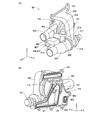
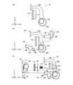
- the schematic perspective view which shows the front side and back side of a piping unit.
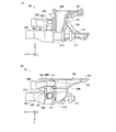
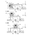
- Schematic which shows the front and upper surface of a piping unit.
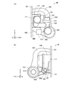
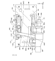
- Schematic which shows the left side surface and right side surface of a piping unit.
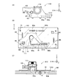
- the schematic front view and schematic top view which show the structure of a cathode gas supply channel
- the schematic sectional drawing which shows the structure of an upstream cathode gas piping and a cathode supply side valve
- the schematic sectional drawing which shows the cross section of downstream cathode gas piping, and the schematic diagram for demonstrating the arrangement position of a hydrogen pump.
- the schematic diagram for demonstrating the downstream cathode gas piping as a comparative example The front view and left view which show the external appearance of cathode bypass piping.
- the left side view and top view which show the structure of an anode gas discharge passage part.
- the schematic diagram which shows the assembly process of a piping unit.
- path part as another structural example.
- the schematic diagram for demonstrating the piping unit as another structural example.
- the schematic diagram for demonstrating the flow of the cathode gas in the downstream cathode gas piping as another structural example.
- the schematic diagram for demonstrating the piping unit as another structural example.
- the schematic diagram for demonstrating the piping unit as another structural example.
- the schematic diagram for demonstrating the piping unit as another structural example.
- the schematic diagram for demonstrating the piping unit as another structural example.
- the schematic diagram for demonstrating cathode bypass piping as another structural example.
- the schematic diagram for demonstrating the cathode bypass piping as another structural example.
- bulb The schematic schematic diagram which shows the anode exhaust gas piping as another structural example.
- separation waste gas piping as another structural example.
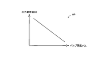
- the schematic block diagram which shows the structure of the fuel cell system as 2nd Example. Explanatory drawing which shows the process sequence of a bypass valve monitoring process. Schematic which shows an example of the map which a bypass valve monitoring part uses.
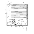
- the schematic top view which shows the structure of the fuel cell unit as 3rd Example.
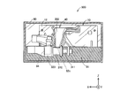
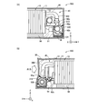
- FIG. 1 is a schematic diagram showing the configuration of a fuel cell system as an embodiment of the present invention.
- the fuel cell system 1000 is mounted on a moving body such as a vehicle, for example, and supplies generated power to a motor or an electrical component that generates a driving force.
- the fuel cell system 1000 includes a fuel cell 10, an air compressor 20, an anode gas supply unit 30, a piping unit 40, a hydrogen pump 50, and a control unit 70.
- the fuel cell system 1000 further includes a refrigerant supply unit for supplying and circulating the refrigerant to the fuel cell 10, but illustration and description thereof are omitted.
- the fuel cell 10 is a polymer electrolyte fuel cell that generates electric power by receiving supply of air (cathode gas) and hydrogen (anode gas) as reaction gases.
- the fuel cell 10 is not limited to a polymer electrolyte fuel cell, and any other various types of fuel cells can be employed.
- a plurality of single cells 11, which are power generators, are stacked in series, and first and second end plates 12 and 13 are disposed at both ends in the stacking direction.
- Each unit cell 11 has a membrane electrode assembly (not shown) in which electrodes are arranged on both surfaces of an electrolyte membrane showing good proton conductivity in a wet state.
- a membrane electrode assembly (not shown) in which electrodes are arranged on both surfaces of an electrolyte membrane showing good proton conductivity in a wet state.
- manifolds (not shown) for supplying and discharging reaction gas are formed as through holes along the stacking direction.
- a fastening member 15 for fastening each single cell 11 is provided outside the membrane electrode assembly so as to penetrate each single cell 11 and the first and second end plates 12 and 13 in the stacking direction. ing.
- the flow of the reaction gas in the fuel cell 10 is shown using broken-line arrows.
- a broken line arrow indicating the cathode gas flow is shown separately on the upper side of the drawing
- a broken line arrow showing the anode gas flow is shown separately on the lower side of the drawing.
- the manifold is formed on the first end plate 12, and is not provided on the second end plate 13. That is, in the fuel cell 10, the reaction gas is supplied from the first end plate 12 side and flows into the membrane electrode assembly of each single cell 11 through the supply manifold to the second end plate 13 side. And flow.
- the exhaust gas containing the unreacted reaction gas discharged from the membrane electrode assembly of each single cell 11 passes from the second end plate 13 side to the first end plate 12 side via the discharge manifold. It flows and is discharged.
- the air compressor 20 is connected to the piping unit 40 via the piping 21.
- the air compressor 20 outputs and supplies the fuel cell 10 with high-pressure air compressed by taking in outside air as cathode gas.
- the anode gas supply unit 30 includes, for example, a hydrogen tank and a reformer for generating hydrogen, and is connected to a supply manifold on the anode side of the fuel cell 10 via an anode gas supply pipe 31. Supply high pressure hydrogen.
- the anode gas supply pipe 31 is provided with a regulator 32 for controlling the hydrogen pressure and an open / close valve 33 for controlling the flow of hydrogen.
- the piping unit 40 is a device for unitizing a part of the fuel cell system 1000 by integrating gas piping and valves for reaction gas connected to the fuel cell 10.
- the fuel cell system 1000 is miniaturized by having the piping unit 40.
- functions of piping and valves unitized in the piping unit 40 will be described.
- the piping unit 40 has a cathode gas supply passage portion 41 for supplying cathode gas to the fuel cell 10 and a cathode gas discharge passage portion 42 for discharging cathode exhaust gas from the fuel cell 10. Further, the piping unit 40 has an anode gas discharge passage portion 43 for discharging anode exhaust gas from the fuel cell 10.
- the cathode gas supply passage 41 includes an upstream cathode gas pipe 100, a cathode supply side valve 110, a downstream cathode gas pipe 120, a cathode bypass pipe 200, and a bypass pipe valve 210.
- the upstream cathode gas pipe 100 is a pipe connecting the pipe 21 connected to the air compressor 20 and the inlet of the cathode supply side valve 110.
- the downstream side cathode gas pipe 120 is a pipe that connects the outlet of the cathode supply side valve 110 and the cathode side supply manifold provided on the first end plate 12.
- the cathode supply side valve 110 is an open / close valve that is opened when a cathode gas having a pressure equal to or higher than a predetermined pressure is supplied.
- the cathode supply side valve 110 includes, for example, a poppet type valve.
- the cathode bypass pipe 200 is a pipe connecting the upstream side cathode gas pipe 100 and the downstream side cathode exhaust gas pipe 320 of the cathode gas discharge passage portion 42.
- the cathode bypass pipe 200 can bypass part of the cathode gas flowing into the upstream cathode gas pipe 100 to the downstream cathode exhaust gas pipe 320.
- the bypass piping valve 210 is provided in the cathode bypass piping 200 and controls the flow rate of the cathode gas (hereinafter also referred to as “cathode bypass gas” or simply “bypass gas”) flowing into the cathode bypass piping 200.
- the cathode gas discharge passage portion 42 includes an upstream side cathode exhaust gas pipe 300, a cathode discharge side valve 310, and a downstream side cathode exhaust gas pipe 320.
- the upstream-side cathode exhaust gas pipe 300 is a pipe for cathode exhaust gas that connects the cathode-side exhaust manifold provided on the first end plate 12 and the inlet of the cathode exhaust-side valve 310.
- the downstream cathode exhaust gas pipe 320 is a pipe for discharging the exhaust gas and drainage of the fuel cell 10 including the cathode exhaust gas to the outside of the system.
- the downstream cathode exhaust gas pipe 320 is connected to the outlet of the cathode discharge side valve 310, and is connected to the cathode bypass pipe 200 and the separation drain pipe 420 of the anode gas discharge passage portion 43.
- the cathode discharge side valve 310 is a valve for controlling the pressure of the cathode exhaust gas.
- the anode gas discharge passage portion 43 includes an anode exhaust gas pipe 400, a separation drain pipe 420, and a separation exhaust pipe 430.
- the anode exhaust gas pipe 400 is a pipe connected to an anode-side discharge manifold provided on the end plate 12, and includes a gas-liquid separation unit 410 and a water storage unit 411.
- the gas-liquid separation unit 410 separates moisture from the inflowing anode exhaust gas, guides it to the water storage unit 411, and guides the remaining anode exhaust gas to the separation exhaust gas pipe 430.
- the separated exhaust pipe 430 is connected to the hydrogen pump 50.
- the hydrogen pump 50 has an outlet connected to the anode gas supply pipe 31 and circulates anode exhaust gas containing unreacted hydrogen to the fuel cell 10.
- the water storage unit 411 is connected to the separation drainage pipe 420 via the anode drainage valve 415, and the separation drainage pipe 420 is connected to the downstream cathode exhaust gas pipe 320.
- the anode-side drainage separated from the anode exhaust gas is normally stored in the water storage unit 411 and discharged to the downstream cathode exhaust gas pipe 320 via the separation drainage pipe 420 when the anode drainage valve 415 is opened. .
- the fuel cell system 1000 measures a pressure gauge and a flow meter that measure the pressure and flow rate of the reaction gas and exhaust gas, a thermometer that detects the operating temperature and the outside air temperature of the fuel cell 10, and a power generation amount of the fuel cell 10. However, illustration and description thereof are omitted. These sensors transmit a measurement result to the control unit 70.
- the control unit 70 is configured by a microcomputer including a central processing unit and a main storage device, and controls the flow of reaction gas in the fuel cell system 1000 based on an output request from an external load and a measurement result of the sensors. Specifically, the control unit 70 controls the air compressor 20 to control the pressure and flow rate of the cathode gas output from the air compressor 20. Further, the controller 70 adjusts the flow rate of the bypass cathode gas by adjusting the opening degree of the bypass piping valve 210, thereby adjusting the pressure and flow rate of the cathode gas supplied to the fuel cell 10.
- valve opening / closing control can be executed with higher responsiveness than air compressor output control.
- the control unit 70 executes the opening / closing control of the bypass piping valve 210 in addition to the output control of the air compressor 20, thereby enabling more prompt adjustment of the cathode gas pressure and flow rate. Can be executed automatically.
- control unit 70 may open the bypass piping valve 210 for warm-up operation of the fuel cell 10 in cold weather or the like.
- the supply amount of the cathode gas to the fuel cell is decreased with respect to the supply amount of the anode gas, the power generation efficiency of the fuel cell is reduced.
- the operation of the fuel cell is continued in a state where the power generation efficiency is lowered, the amount of heat generated by the fuel cell with respect to the amount of power generation increases. That is, in the fuel cell system 1000 of this embodiment, when the fuel cell 10 is in a low temperature state, the fuel cell is operated with low power generation efficiency by opening the bypass piping valve 210 and reducing the supply amount of the cathode gas. By continuing to 10, the fuel cell 10 can be warmed up.
- the supply amount of the cathode gas is preferably controlled in the vicinity of a limit value that does not stop the power generation of the fuel cell 10.
- the flow rate of the cathode gas can be controlled more promptly by the control of the bypass piping valve 210. Therefore, the control of the cathode gas for the warm-up operation is possible. Can be executed more appropriately.
- the control unit 70 further controls the opening degree of the cathode discharge side valve 310 to adjust the pressure of the cathode gas in the fuel cell 10. Further, the control unit 70 controls the flow rate and pressure of the anode gas supplied to the fuel cell 10 by controlling the regulator 32 and the opening / closing valve 33 provided in the anode gas supply pipe 31. Further, the control unit 70 opens the anode drain valve 415 at a predetermined timing, and executes drainage of the water stored in the water storage unit 411.
- FIG. 2 to 4 are schematic views showing the appearance of the piping unit 40.
- FIG. 2 to 4 three-dimensional arrows X, Y, and Z that are orthogonal to each other are shown so as to correspond to each other.
- the piping unit 40 is attached to a predetermined position (described later) on the outer surface of the first end plate 12 of the fuel cell 10.
- the fuel cell 10 is arranged in a predetermined arrangement direction (described later). It is arranged with. That is, the piping unit 40 is arranged and used in a predetermined arrangement direction in the fuel cell system 1000.
- the three-dimensional arrows X, Y, and Z in each figure are illustrated with reference to the direction of arrangement when the piping unit 40 is used in the fuel cell system 1000.
- the arrow Z is an arrow indicating a direction (height direction) opposite to the direction of gravity.
- An arrow Y is an arrow indicating a direction from the second end plate 13 toward the first end plate 12 along the stacking direction of the fuel cells 10.
- An arrow X is an arrow indicating the left direction when the arrow Z is directed vertically upward and is directed in a direction opposite to the arrow Y.
- the surface of the piping unit 40 when viewed in the direction opposite to the arrow Y is referred to as “front”, and the opposite surface is referred to as “back”.
- the surface of the piping unit 40 when viewed in the direction of the arrow X is referred to as a “right side surface”, and the opposite surface is referred to as a “left side surface”.
- the surface of the piping unit 40 when viewed in the direction opposite to the arrow Z (the direction of gravity) is referred to as the “upper surface”, and the opposite surface is referred to as the “bottom surface”.
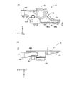
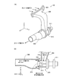
- FIG. 2A is a schematic perspective view showing the front side of the piping unit 40
- FIG. 2B is a schematic perspective view showing the back side of the piping unit 40
- FIG. 3A is a schematic diagram showing the front of the piping unit 40
- FIG. 3B is a schematic diagram showing the top surface of the piping unit 40
- FIG. 4A is a schematic diagram showing the left side surface of the piping unit 40
- FIG. 4B is a schematic diagram showing the right side surface of the piping unit 40.
- the cathode supply side valve 110 has a substantially cylindrical casing with the direction along the arrow Y in the height direction, and is disposed at the substantially central portion of the piping unit 40.
- the upstream cathode gas pipe 100 is configured as a pipe extending in the direction along the arrow X, and is connected to a cylindrical side surface of the casing of the cathode supply side valve 110.
- An outlet 111 that opens toward the back side of the piping unit 40 is provided on the bottom surface of the cylinder on the back side of the cathode supply side valve 110, and a downstream cathode gas pipe 120 is provided on the outer periphery of the outlet 111.
- the downstream cathode gas pipe 120 opens toward the back side of the pipe unit 40 (in the direction opposite to the arrow Y), and the outer wall that forms the opening of the downstream side of the outlet 111 of the cathode supply side valve 110. It is formed so as to surround the outer periphery and spread toward the lower side in the direction of gravity. The flow of the cathode gas in the downstream cathode gas pipe 120 will be described later.
- a flange 121 for fixing the piping unit 40 to the first end plate 12 is formed on the outer periphery of the opening of the downstream side cathode gas piping 120. Further, a thinned portion 119 is formed on the back side of the flange 121, and the thinned portion 119 will be described later.
- the downstream cathode exhaust gas pipe 320 is configured as a pipe extending in parallel with the upstream cathode gas pipe 100 at a position on the arrow Y direction side and in the gravity direction lower side than the upstream cathode gas pipe 100.
- the cathode discharge side valve 310 has a substantially cylindrical casing with the direction along the arrow X in the height direction.
- the cathode discharge side valve 310 has a lower position than the downstream cathode exhaust gas pipe 320 at a position below the cathode supply side valve 110. Connected in series. Note that a motor 311 for driving the valve body of the cathode supply side valve 110 is disposed at the downstream side in the series direction of the casing of the downstream side cathode exhaust gas pipe 320 and the cathode supply side valve 110.
- the upstream cathode exhaust gas pipe 300 is configured as a pipe extending along the outer surface of the cathode supply side valve 110 from the cylindrical side surface in the casing of the cathode discharge side valve 310 to the upper side in the gravity direction.
- the upstream side cathode exhaust gas pipe 300 has a downstream side extending toward the upper side in the gravity direction along the upper surface of the cylinder in the casing of the cathode supply side valve 110 and the upstream side along the side surface of the cylinder in the casing of the cathode supply side valve 110. Extending to the back side.
- An upstream end of the upstream cathode exhaust gas pipe 300 is open to the back side, and a flange 301 for connection to the first end plate 12 is formed on the outer periphery of the opening.
- the cathode bypass pipe 200 is provided at a position adjacent to the cathode supply side valve 110 and the upstream side cathode exhaust gas pipe 300.
- the cathode bypass pipe 200 is constituted by a bent pipe, and an upstream pipe section 201 extending from the upstream cathode gas pipe 100 to the front side, and extending from the upstream pipe section 201 in the direction of gravity to the downstream cathode.
- a downstream pipe section 202 connected to the exhaust gas pipe 320.
- the bypass piping valve 210 is provided inside the downstream piping section 202, and details thereof will be described later.
- a motor 211 for driving the valve body of the bypass piping valve 210 is disposed above the downstream side piping section 202.
- the anode exhaust gas pipe 400 is provided below the upstream side cathode exhaust pipe 300 and the cathode bypass pipe 200.
- the anode exhaust gas pipe 400 has an opening 401 for connection to a discharge manifold on the anode side.
- the opening 401 is open on the back surface side, and a flange 402 for connecting to the first end plate 12 is formed on the outer periphery thereof.
- a thinned portion 403 is formed on the back side of the flange 402.
- the flange 402 for the anode exhaust gas pipe 400 and the flange 121 for the downstream cathode gas pipe 120 are integrated.
- the cathode gas supply passage portion 41 and the anode gas discharge passage portion 43 can be integrally attached to the fuel cell 10.
- these flanges 121 and 402 are formed so as to widely cover the outer surface of the first end plate 12. Accordingly, the flanges 121 and 402 also function as a heat insulating material for suppressing heat dissipation to the outside of the fuel cell 10.
- the lightening portion 403 formed on the back side of the flange 402 is airtightly closed by the outer surface of the first end plate 12 and functions as a heat insulating layer for suppressing heat radiation to the outside of the fuel cell 10. .
- a gas-liquid separation unit 410 and a water storage unit 411 are provided inside the anode exhaust gas pipe 400, and the detailed configuration thereof will be described later.
- a separation drainage pipe 420 is disposed between the anode exhaust gas pipe 400 and the downstream cathode exhaust gas pipe 320.
- an anode drain valve 415 for connecting the water storage section 411 provided in the anode exhaust pipe 400 and the separation drain pipe 420 is provided on the left side of the anode exhaust gas pipe 400 and the separation drain pipe 420.
- a separated exhaust gas pipe 430 is connected to the right side surface of the anode exhaust gas pipe 400. The separated exhaust pipe 430 extends in the direction opposite to the arrow X below the cathode supply side valve 110.
- the piping unit 40 is attached to a predetermined position on the outer surface of the first end plate 12 of the fuel cell 10. Below, the specific attachment position is demonstrated.
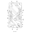
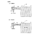
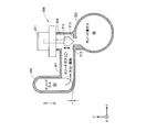
- FIG. 5 is an explanatory diagram for explaining the attachment position of the piping unit 40 to the fuel cell 10.
- FIG. 5 schematically shows the outer surface of the first end plate 12 of the fuel cell 10, and the outer circumferences of the flanges 121, 402, and 301 when the piping unit 40 is attached are indicated by broken lines. It is.
- a seal line SL formed between the piping unit 40 and the first end plate 12 when the piping unit 40 is attached is indicated by a one-dot chain line.
- a position where the outlet 111 of the cathode supply side valve 110 is arranged is illustrated by a two-dot chain line, and an arrow indicating a flow of the cathode gas flowing out from the outlet 111 is illustrated.
- the first end plate 12 is composed of a substantially rectangular plate member.
- the fuel cell 10 is arranged such that the long side direction of the first end plate 12 and the stacking direction of the fuel cells 10 are horizontal.
- the direction of gravity when the fuel cell 10 is arranged in the fuel cell system 1000 is shown as an arrow G.
- the first end plate 12 is provided with anode-side supply and discharge manifolds M1 and M2, cathode-side supply manifolds M3a and M3b, and two discharge manifolds M4a and M4b. .
- the manifolds M1, M2, M3a, M3b, M4a, and M4b are arranged along the long side of the first end plate 12. More specifically, the two supply manifolds M3a and M3b on the cathode side are provided so as to be arranged along one long side of the first end plate 12, and the two discharge manifolds M4a and M4b are It is provided so as to be arranged substantially along the other long side.
- the anode-side supply manifold M1 is provided on the same side as the cathode-side discharge manifolds M4a and M4b, and the anode-side discharge manifold M2 is provided on the same side as the cathode-side supply manifolds M3a and M3b. It has been.
- the anode-side supply manifold M1 and the discharge manifold M2 are formed so as to be diagonal to each other across the central region of the first end plate 12.
- the first end plate 12 has a supply manifold M5 and a discharge manifold M6 facing each other with the central region of the first end plate 12 sandwiched therebetween. It is formed along two short sides.
- a fastening member 15 for fastening the fuel cell 10 is attached to the first end plate 12 so as to penetrate in the thickness direction.
- the fastening members 15 are provided at the four corners of the first end plate 12, between the first supply manifold 3a and the second supply manifold 3b on the cathode side, and between the first discharge manifold 4a and the second discharge manifold 3b. It is provided between the manifolds 4b.
- the fuel cell 10 is arranged with the supply manifolds M3a and M3b on the cathode side on the upper side in the gravity direction and the discharge manifolds M4a and M4b on the lower side in the gravity direction.
- the cathode gas flows from the lower side to the upper side in the direction of gravity on the cathode side of each unit cell 11.
- the electrolyte membrane is kept in a wet state during the operation.
- the moisture in the electrolyte membrane of each single cell 11 receives a force against the gravity by the flow of the cathode gas and can move according to the gravity. It is suppressed. That is, by disposing the fuel cell 10 as described above, the water retention of the electrolyte membrane in the operating fuel cell 10 can be improved.
- a cathode supply side valve 110 is disposed between the supply manifolds M3a and M3b on the cathode side and the discharge manifolds M4a and M4b, and the cathode supply side
- the outlet 111 of the valve 110 opens toward the outer surface of the first end plate 12.
- the two supply manifolds M3a and M3b on the cathode side are arranged in the region of the lower end in the gravity direction in the opening of the downstream cathode gas pipe 120, and the discharge manifold M2 on the anode side is the opening of the anode exhaust gas pipe 400 401 is linked.
- the two discharge manifolds M4a and M4b on the cathode side are arranged in the opening at the upstream end of the upstream cathode exhaust gas pipe 300.
- a seal member (not shown) is arranged on the outer periphery of the opening of each of the pipes 120, 300, 400, and when the pipe unit 40 is fixed to the first end plate 12, the seal line SL. Is formed.
- the seal line SL formed by the downstream-side cathode gas pipe 120 is formed so as to surround the arrangement region of the outlet 111 of the cathode supply side valve 110 and the supply manifolds M3a and M3b on the cathode side.
- the opening of the downstream side cathode gas pipe 120 is closed by the outer surface of the first end plate 12, thereby connecting the outlet 111 of the cathode supply side valve 110 and the two supply manifolds M3a and M3b.
- the cathode gas flows in the space along the outer surface of the first end plate 12, and flows into the supply manifolds M3a and M3b on the cathode side.
- the piping unit 40 uses the outer surface of the first end plate 12 as a guide wall for guiding the cathode gas from the outlet 111 of the cathode supply side valve 110 to the supply manifolds M3a and M3b.
- the water retention in the electrolyte membrane of each single cell 11 is improved by flowing the cathode gas in the direction opposite to the direction of gravity. Therefore, when the supply of the cathode gas is stopped, such as after the operation of the fuel cell 10 is stopped, the moisture on the cathode side of each unit cell 11 may flow back to the supply manifolds M3a and M3b according to gravity. is there.
- the cathode supply side valve 110 is disposed above the first and second supply manifolds M3a and M3b, the moisture inside the fuel cell 10 after the operation is stopped. However, the flow into the cathode supply side valve 110 is suppressed. Therefore, freezing of the cathode supply side valve 110 and deterioration of the cathode supply side valve 110 in a low temperature environment due to such backflow moisture are suppressed.
- a plurality of piping and valves for supplying and discharging the reaction gas are integrated, and these can be integrally attached to the fuel cell 10. it can. Further, since each of the components 41 to 43 of the piping unit 40 is configured compactly, and is integrated with the fuel cell 10 and disposed in the fuel cell system 1000, the fuel cell system 1000 can be reduced in size. .
- the constituent parts 41 to 43 are configured as follows in order to improve the power generation efficiency of the fuel cell 10 and to suppress the deterioration of the fuel cell 10.
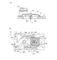
- FIG. 6A is a schematic front view showing the cathode gas supply passage 41
- FIG. 6B is a schematic top view showing the cathode gas supply passage 41.
- FIG. 6A and 6B show three-dimensional arrows X, Y, and Z similar to those in FIGS.
- FIG. 6A the arrangement positions of the supply manifolds M3a and M3b on the cathode side and the fastening member 15 in the downstream cathode gas pipe 120 when attached to the fuel cell 10 are shown by broken lines. .
- FIGS. 6A and 6B also show a flange 402 for the anode exhaust gas pipe 400 integrated with the flange 121.
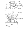
- FIG. 7 (A) is a schematic cross-sectional view of the cathode supply side valve 110 taken along the line AA shown in FIG. 6 (A).
- the cathode supply side valve 110 is a poppet type valve and includes a valve body 112, a diaphragm 113, an urging mechanism 114, a casing 117, and a casing cap portion 118.
- the main body of the casing 117 has a substantially cylindrical shape.
- the outlet 111 is provided as a substantially circular opening at the center of the bottom, and the flange 121 is provided on the outer periphery of the outlet 111.
- an inlet 115 to which the upstream cathode gas pipe 100 is connected is provided as a substantially rectangular opening on the side surface of the main body of the casing 117.
- the entire upper surface of the casing 117 is open, and is closed by attaching the casing cap portion 118.
- the opening end of the casing cap 118 is provided with a portion bent outward in a substantially L shape so that the opening end of the casing 117 can be covered and crimped.
- Diaphragm 113 is a substantially disk-shaped thin film having elasticity in the thickness direction, and the outer peripheral end thereof is held between the opening ends of casing 117 and casing cap portion 118, so that casing 117 and casing cap portion 118 Held between.
- the internal space of the cathode supply side valve 110 is divided by the diaphragm 113 into an internal space on the casing 117 side and an internal space on the casing cap portion 118 side. Note that the internal space on the casing 117 side and the internal space on the casing cap portion 118 side are hermetically sealed by the diaphragm 113.
- the internal space on the casing cap 118 side is in communication with the outside so as to be maintained at atmospheric pressure.
- a valve body 112 is attached to the surface of the diaphragm 113 on the casing 117 side so as to close the outlet 111.
- An urging mechanism 114 is attached to the surface of the diaphragm 113 on the casing cap part 118 side. The urging mechanism 114 urges the valve body 112 to the valve seat 116 on the outer periphery of the outlet 111 via the diaphragm 113.
- the cathode supply side valve 110 is normally closed.
- the cathode gas is supplied from the inlet 115 to the internal space on the casing 117 side at a predetermined pressure
- the diaphragm 113 is bent toward the casing cap portion 118 side by the gas pressure. Therefore, the valve body 112 is separated from the valve seat 116 on the outer periphery of the outlet 111, and the cathode supply side valve 110 is opened.
- the cathode supply side valve 110 is fixedly attached to the first end plate 12 by a flange 121 provided on the outer periphery of the downstream side cathode gas pipe 120. As described above, the cathode supply side valve 110 is repeatedly opened and closed according to the supply pressure of the cathode gas when the fuel cell 10 is operated. Therefore, if the cathode supply side valve 110 is fixed to the first end plate 12 formed of a relatively rigid member, it is possible to suppress vibrations associated with the opening / closing operation of the cathode supply side valve 110. .
- the contact surface side with the first end plate 12 (right side on the paper surface) is directed to the seat surface side (left side with respect to the paper surface) of the valve seat 116.
- the meat extraction part 119 is formed by performing the meat extraction.
- the lightening portion 119 reduces the weight of the cathode supply side valve 110.
- FIG. 7B is a schematic cross-sectional view showing a cathode supply side valve 110a as a reference example.
- FIG. 7B is almost the same as FIG. 7A except that the lightening direction of the lightening part 119a is different.
- the thinned portion 119a below the valve seat 116 is formed by being thinned from the side surface direction (the vertical direction on the paper surface) of the casing 117.
- the rigidity for supporting the seat surface of the valve seat 116 with respect to the pressing direction by the valve body 112 may be insufficient by forming the thinned portion 119a. That is, the sealing performance between the valve seat 116 and the valve body 112 may be deteriorated.
- the thinned portion 119 can be formed while leaving a wall portion (rib) for supporting the seat surface of the valve seat 116. . Therefore, it is possible to reduce the weight of the cathode supply side valve 110 while suppressing a decrease in rigidity of the valve seat 116.
- FIG. 7C is a schematic cross-sectional view of the upstream side cathode gas piping 100 and the cathode supply side valve 110 in the CC cutting shown in FIG. 6B.
- FIG. 7C illustration of the cathode supply side valve 110 other than the casing 117 is omitted, and an arrow indicating the flow of the cathode gas is shown.
- FIGS. 7D and 7E are schematic cross-sectional views of the upstream cathode gas pipe 100 in the DD cutting and the EE cutting shown in FIG. 7C, respectively.
- 7C to 7E show three-dimensional arrows X, Y, and Z corresponding to FIG.
- the upstream cross-section of the upstream-side cathode gas pipe 100 has a substantially circular shape in order to facilitate connection to an external pipe and attachment of components such as a waterproof grommet. Therefore, in the upstream cathode gas pipe 100 of the present embodiment, the upstream-side channel cross section has a substantially circular shape (FIG. 7D). On the other hand, it is preferable that the downstream cross section of the upstream cathode gas pipe 100 has a shape that matches the opening shape of the inlet 115 of the cathode supply side valve 110.
- the opening area of the inlet 115 is large in order to suppress an increase in pressure loss of the inflowing cathode gas. It is preferable to narrow the opening width of the inlet 115 in the selected direction. Further, in the cathode supply side valve 110, in order to improve the flowability of the cathode gas flowing from the inlet 115 to the outlet 111, the inlet 115 has a channel width in the direction along the arrow Z with respect to the outlet 111. The wider one is preferable. Therefore, in this embodiment, the inlet 115 of the cathode supply side valve 110 is formed as a rectangular opening having a long side in the circumferential direction of the casing 117 (FIG. 7A).
- the flow path width in the direction along the arrow Z is enlarged according to the opening shape of the inlet 115, and the flow path width in the direction along the arrow Y is expanded. It has an elongated shape with a reduced channel width (FIG. 7E).
- the upstream cathode gas piping 100 of the present embodiment is configured so that the shape of the flow path cross section changes from the upstream side to the downstream side.
- the upstream-side cathode gas pipe 100 preferably has a flow passage cross-sectional area that is substantially constant from the upstream side to the downstream side. It is preferable that the change in the cross-sectional shape of the channel from the side to the downstream side is more gradual.
- FIG. 8A is a schematic cross-sectional view showing a cross section of the downstream cathode gas pipe 120 in the DD cut shown in FIG. 6A.
- FIG. 8A shows a state where the downstream cathode gas pipe 120 is attached to the first end plate 12.
- a fastening member 15 is disposed between the first and second supply manifolds M3a and M3b on the cathode side.
- the downstream side cathode gas piping 120 when the top of the fastening member 15 protrudes from the outer surface of the first end plate 12, the flow of the cathode gas is hindered by the top, and the cathode Gas pressure loss may increase.
- the convex wall portion 122 is formed by curving the outer wall of the portion covering the top of the fastening member 15 outward, so that the channel cross-sectional area of the portion is reduced. The decrease is suppressed. This suppresses a decrease in the flowability of the cathode gas with respect to the second supply manifold M3b.
- FIG. 8B is a schematic diagram for explaining the arrangement position of the hydrogen pump 50.
- FIG. 8B is almost the same as FIG. 5 except that the region for arranging the hydrogen pump 50 is shown by cross-hatching.
- the anode exhaust gas is circulated through the hydrogen pump 50 to the anode gas supply pipe 31 (FIG. 1). Since the piping unit 40 has the separated exhaust gas piping 430 for guiding the anode exhaust gas, the hydrogen pump 50 includes the piping unit 40 and the supply manifold M1 on the anode side in order to reduce the size of the fuel cell system 1000. It is preferable to arrange
- the outer wall of the downstream cathode gas pipe 120 is formed so as to extend from the outlet 111 of the cathode supply side valve 110 toward the first and second supply manifolds M3a and M3b on the cathode side.
- the outer wall on the side adjacent to the arrangement area of the hydrogen pump is provided with a bent portion 123 so as to be recessed toward the flow path.
- the bent portion 123 reduces the area of the flow path formed by the downstream cathode gas pipe 120 on the outer surface of the first end plate 12 and secures an arrangement area for the hydrogen pump 50.
- the gas flow path downstream of the formation part of the bent portion 123 has a relatively small flow path cross-sectional area, and pressure loss tends to increase. Therefore, if the fastening member 15 is disposed on the downstream side of the bent portion 123, the pressure loss on the downstream side of the bent portion 123 may be further increased. Therefore, in order to improve the flowability of the cathode gas with respect to the first and second supply manifolds M3a and M3b, the bent portion 123 is connected to the second supply manifold M3b rather than the portion where the convex bay portion 122 is formed. It is preferable that it is formed at a close position. As a result, the flow path cross-sectional area on the downstream side of the bent portion 123 can be secured, and an increase in pressure loss can be suppressed.
- FIG. 9 is a schematic diagram for explaining a downstream cathode gas pipe 120a as a comparative example.
- 9A and 9B schematically show the fuel cell 10, the upstream cathode gas pipe 100, the cathode supply side valve 110, and the downstream cathode gas pipe 120a. The components of the fuel cell system are omitted.
- FIG. 9A shows the fuel cell 10 during operation
- FIG. 9B shows the fuel cell 10 after being stopped.
- the downstream-side cathode gas pipe 120 a is configured by a resin-made pipe, and the cathode supply side valve 110 that is spaced apart from the first end plate 12 and the cathode of the first end plate 12. Is connected to the supply manifold on the side.
- downstream cathode gas passage of this comparative example has a flow passage volume corresponding to the cathode supply side valve 110 disposed away from the first end plate 12, and the downstream cathode gas pipe 120 of this embodiment. It is assumed that it is larger than the flow path volume.
- the cathode supply side valve 110 is closed (FIG. 9B).
- the cathode discharge side valve 310 and the open / close valves provided in the anode gas supply pipe 31 are also closed. That is, the fuel cell 10 is sealed with the reaction gas remaining. In the sealed fuel cell 10, a part of the remaining hydrogen leaks to the cathode side through the electrolyte membrane in each single cell 11, and the oxygen on the cathode side reacts with the leaked hydrogen. Is consumed.
- the downstream side cathode gas pipe 120a which is a resin pipe
- the downstream cathode gas pipe 120a is deformed in a contracting direction.
- the contracted downstream cathode gas pipe 120a may be rapidly deformed in the expanding direction, and an abnormal noise may be generated along with the deformation. If such shrinkage / expansion deformation is repeated, deterioration of the downstream cathode gas pipe 120a may be promoted.
- the downstream cathode gas pipe 120a is made of a highly rigid member so that such deformation does not occur in the downstream cathode gas pipe 120a, the weight may increase significantly. .
- the distance between the outlet 111 of the cathode supply side valve 110 and the supply manifolds M3a and M3b on the cathode side is configured to be relatively short, and the first end plate 12
- the outer surface is used as the wall surface of the gas passage. Therefore, even if the rigidity of the outer wall is improved so that the downstream cathode gas pipe 120 does not deform due to the generation of negative pressure after the operation of the fuel cell 10 is stopped, the increase in weight is relatively suppressed. Is done. That is, with the piping unit 40 of the present embodiment, it is possible to easily suppress the deformation of the downstream-side cathode gas piping 120 and the accompanying noise generation after the operation of the fuel cell 10 is stopped.
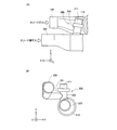
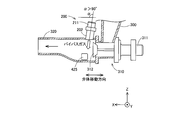
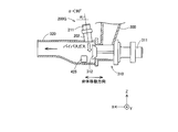
- FIG. 10A is a front view showing the appearance of the cathode bypass pipe 200
- FIG. 10B is a left side view showing the appearance of the cathode bypass pipe 200
- FIG. 10A and 10B show the upstream cathode gas pipe 100 to which the cathode bypass pipe 200 is connected and a part of the downstream cathode exhaust gas pipe 320
- FIG. 11 is a schematic view showing the internal configuration of the cathode bypass pipe 200 as seen through.
- FIG. 11 shows a schematic cross section of the upstream cathode gas pipe 100 and the downstream cathode exhaust gas pipe 320 to which the cathode bypass pipe 200 is connected.
- 10 and 11 show three-dimensional arrows X, Y, and Z similar to those in FIGS.
- the upstream side pipe portion 201 of the cathode bypass pipe 200 is connected to the upstream side cathode gas pipe 100 so that the bottom surface of the flow path is lower than the bottom surface of the upstream side cathode gas pipe 100 in the direction of gravity. It is connected to the gas pipe 100 (FIG. 11).
- the cathode gas taken in from the outside air by the air compressor 20 flows into the upstream side cathode gas pipe 100.
- foreign matters such as dust and rainwater contained in the cathode gas are guided to the cathode bypass pipe 200 according to gravity. Is done. Therefore, it is possible to suppress rainwater and foreign matters in the cathode gas from flowing into the fuel cell 10 and to suppress deterioration of the fuel cell 10.
- a bypass piping valve 210 is provided in the downstream piping section 202. Specifically, a valve body 212 that moves along the piping direction is arranged inside the downstream pipe section 202, and a valve seat 213 for receiving the valve body 212 on the lower side in the gravity direction is provided. It has been. That is, the downstream side piping section 202 functions as a valve chamber of the bypass piping valve 210. A direct acting motor 211 for driving the valve body 212 is disposed above the downstream side piping section 202. The motor 211 and the downstream piping section 202 are sealed with a diaphragm (not shown).
- the bypass piping valve 210 is configured to be closed when the valve body 212 moves downward in the direction of gravity.
- the valve body 212 is likely to move to the closed side according to gravity.
- the possibility of pressure bonding to the valve seat 213 increases due to the pressure of the bypass gas. Therefore, it can be avoided that the cathode 211 leaks more than necessary due to the failure of the motor 211 and the operation is continued while the power generation efficiency of the fuel cell 10 is lowered.
- the motor 211 is disposed above the bypass gas flow path in the direction of gravity, so that the water flowing into the cathode bypass piping 200 moves to the motor 211 side and deteriorates the motor 211. It is suppressed to let it be.
- downstream side piping section 202 is connected at a position offset from the center of the downstream side cathode exhaust gas piping 320 so that the central axis does not intersect the central axis of the downstream side cathode exhaust gas piping 320. Is preferred.
- the bypass gas flowing into the downstream cathode exhaust gas pipe 320 flows along the inner wall surface of the downstream cathode exhaust gas pipe 320, and eddy current is easily generated in the downstream cathode exhaust gas pipe 320.
- the downstream side piping section 202 is connected to the downstream side cathode exhaust gas pipe 320 so as to have an inclination angle for scavenging in the downstream side cathode exhaust gas pipe 320 (FIG. 10A). Details thereof will be described later.
- FIGS. 12A and 12B are schematic views for explaining a more detailed configuration of the cathode gas discharge passage portion 42.
- FIG. FIG. 12A is a schematic perspective view showing the cathode gas discharge passage portion 42, and illustration of components other than the cathode gas discharge passage portion 42 in the piping unit 40 is omitted.
- FIG. 12B is a schematic view showing a part of the upstream cathode exhaust gas pipe 300, the cathode discharge side valve 310, and the internal structure of the downstream cathode exhaust gas pipe 320 as seen through.
- FIGS. 12A and 12B three-dimensional arrows X, Y, and Z similar to those in FIGS. 2 to 4 are shown.
- the cathode discharge side valve 310 is a poppet type valve in which the valve body 315 moves in the direction along the arrow X, and has a substantially cylindrical casing.
- the inlet 312 is provided on the side surface of the casing, and the upstream side cathode exhaust gas pipe 300 is connected from the upper side in the gravity direction.
- the outlet 313 is provided on the bottom surface of the casing so as to open in the direction of the arrow X, and a motor 311 for driving the valve body 315 is arranged on the bottom surface of the opening opposite to the outlet 313.
- the valve seat 314 is provided on the outer periphery of the outlet 313 outside the casing. That is, in the cathode discharge side valve 310, the main body of the valve body 315 is disposed outside the casing, and the valve body 315 is closed when the main body of the valve body 315 moves from the downstream cathode exhaust gas pipe 320 side to the casing side. With this arrangement of the valve body 315, even if the valve body 315 is in a floating state due to a failure of the motor 311 or the like, the valve body 315 is moved to the open side by the cathode exhaust gas. Therefore, the operation of the fuel cell 10 can be continued.
- FIGS. 13A to 13C are schematic cross-sectional views for explaining the configuration of the upstream cathode exhaust gas pipe 300, respectively.
- FIG. 13A shows a schematic cross section of the casing of the upstream side cathode exhaust gas pipe 300 and the cathode discharge side valve 310.
- FIG. 13A shows three-dimensional arrows X, Y, and Z corresponding to FIG.
- the upstream side cathode exhaust gas pipe 300 includes an upstream side pipe part 302 extending from the flange 301 to the front side of the pipe unit 40 (in the direction of arrow Y), and a downstream side pipe bent from the upstream side pipe part 302 and extending downward. Part 303.
- moisture contained in the cathode exhaust gas may be condensed in the upstream side cathode exhaust gas pipe 300. If the liquid water W condensed in the upstream cathode exhaust gas pipe 300 flows into the cathode discharge side valve 310, the cathode discharge side valve 310 may be frozen in a low temperature environment such as below freezing point. .
- the upstream side piping section 302 of the upstream side cathode exhaust gas piping 300 of the present embodiment is configured such that the bottom surface thereof is inclined upward toward the downstream side.
- the upstream side piping part 302 the liquid water discharged from the discharge manifolds M ⁇ b> 4 a and M ⁇ b> 4 b can be temporarily retained on the bottom surface of the upstream side piping part 302 during the operation of the fuel cell 10. Accordingly, a large amount of waste water is prevented from flowing into the cathode side discharge valve 310 at a time.
- FIGS. 13B and 13C are schematic cross-sectional views of the upstream-side cathode exhaust gas pipe 300 in the BB cutting and the CC cutting shown in FIG. 13A, respectively.
- the flow path cross-sectional area is made substantially uniform from the upstream side to the downstream side so that an increase in pressure loss of the cathode exhaust gas is suppressed.
- the upstream cathode exhaust gas pipe 300 is configured so that the shape of the flow path section gradually changes from the upstream side to the downstream side.
- the cross-sectional shape of the flow path of the upstream side piping section 302 is configured to be wide in accordance with the arrangement direction of the discharge side manifolds M4a and M4b on the cathode side. This suppresses an increase in pressure loss when the cathode exhaust gas flows from the manifolds M4a and M4b into the upstream cathode exhaust pipe 300.
- the channel cross-sectional shape of the downstream side piping section 303 is a shape that matches the opening shape of the inlet 312 of the cathode discharge side valve 310.
- the cathode discharge side valve 310 is configured to be narrow in the direction along the moving direction of the valve body 315 and is configured to be wide in the circumferential direction of the casing of the cathode discharge side valve 310. Yes.
- an increase in pressure loss when the cathode exhaust gas flows into the cathode discharge side valve 310 is suppressed.
- the size of the cathode discharge side valve 310 in the arrow X direction can be reduced. Miniaturization is possible.
- the change in the cross-sectional shape of the flow channel from the upstream side to the downstream side in the upstream side cathode exhaust gas pipe 300 is gradually changed so that the occurrence of contraction of the cathode exhaust gas is suppressed.
- the corners of the upstream-side cathode exhaust gas pipe 300 may be rounded so as not to hinder the attachment of other components (for example, the connector of the motor 211 of the bypass pipe valve 210) in the pipe unit 40. .
- the curvature at that time may be gradually changed from the upstream side to the downstream side.
- FIGS. 14A and 14B are schematic views for explaining a more detailed configuration of the anode gas discharge passage portion 43.
- FIG. FIG. 14A is a schematic view showing the left side surface of the anode gas discharge passage portion 43.
- FIG. 14A shows a separation drainage pipe 420 and a downstream side cathode exhaust gas pipe 320.
- FIG. 14B is a schematic view showing the upper surface of the anode gas discharge passage portion 43 when viewed in the direction of gravity.
- FIG. 14B shows a part of the downstream cathode exhaust gas pipe 320 and the flange 121 integrated with the flange 402, and the cathode supply side valve 110 and the downstream cathode gas pipe 120 are shown by broken lines. Has been.
- a downstream portion of the cathode exhaust gas pipe 320 in FIG. 14B shows a connection portion 205 with the cathode bypass pipe 200.
- 14A and 14B show three-dimensional arrows X, Y, and Z similar to those shown in FIGS.
- the anode exhaust gas pipe 400 has a substantially hexahedral casing in which the upper surface is configured by a horizontal surface and the bottom surface is configured by an inclined surface that becomes lower toward the downstream side.
- the gas-liquid separation unit 410 and the water storage unit 411 provided inside the anode exhaust gas pipe 400 will be described later.
- the separation drainage pipe 420 extends from the lower part on the front side of the anode exhaust gas pipe 400 in the direction of the arrow X and is connected to the downstream cathode exhaust gas pipe 320. Note that the separation drain pipe 420 is arranged to have a step with respect to the anode exhaust gas pipe 400.
- the upper surface of the separation drainage pipe 420 is constituted by a horizontal plane located below the upper surface of the anode exhaust gas pipe 400. Further, the bottom surface of the separation drainage pipe 420 is located below the bottom surface of the anode exhaust gas pipe 400 and is formed by an inclined surface having an inclination angle similar to that of the bottom surface of the anode exhaust gas pipe 400.
- the anode drain valve 415 is installed adjacent to the left side surfaces of the anode exhaust gas pipe 400 and the separation drain pipe 420. A drainage mechanism by the anode drain valve 415 will be described later.
- the separated exhaust gas pipe 430 is configured by a pipe extending in the direction opposite to the arrow X from the right side surface on the relatively downstream side of the anode exhaust gas pipe 400. The separated exhaust gas pipe 430 extends close to and in parallel with the downstream cathode gas pipe 120, thereby enabling heat exchange between the cathode gas and the anode exhaust gas.
- the fuel cell 10 is not sufficiently heated, such as when the fuel cell system 1000 is started up.
- the piping unit 40 of the present embodiment a part of the exhaust heat of the cathode gas whose temperature rises relatively early can be transmitted from the downstream cathode gas pipe 120 to the anode exhaust gas of the separated exhaust gas pipe 430. it can.
- the anode exhaust gas in the separation exhaust gas pipe 430 is circulated to the anode gas supply pipe 31 via the hydrogen pump 50 (FIG. 1).
- the heat exchange between the separated exhaust gas pipe 430 and the downstream cathode gas pipe 120 in the pipe unit 40 causes the exhaust heat of the cathode gas to be transmitted to the fuel cell 10 via the anode exhaust gas, and the fuel cell 10 rises.
- the temperature can be executed efficiently.
- the flange 121 of the downstream cathode gas pipe 120 and the flange 402 of the anode exhaust gas pipe 400 are integrated. Therefore, since the exhaust heat of the cathode gas is transmitted to the anode exhaust gas also through the flanges 121 and 402, the temperature of the fuel cell 10 is raised more efficiently.
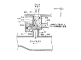
- 15 (A) and 15 (B) are schematic schematic views showing the internal structure of the anode gas discharge passage 43 shown in FIGS. 14 (A) and 14 (B), respectively.
- 15A and 15B show three-dimensional arrows X, Y, and Z so as to correspond to FIGS. 14A and 14B, respectively.
- FIG. 15A the attachment position of the anode drain valve 415 and the position of the inlet 4151 are indicated by broken lines.
- FIG. 15B the two bottom surfaces 412 and 413 of the anode exhaust gas pipe 400 are distinguished from each other by different hatchings.
- a gas-liquid separator 410 is provided inside the casing of the anode exhaust gas pipe 400.
- the gas-liquid separation unit 410 has a high floor surface 412 formed at a relatively high position and a low floor surface 413 formed at a relatively low position.
- the high floor surface 412 has substantially the same height as the bottom surface of the inlet 401 of the anode exhaust gas pipe 400, and is configured as a continuous horizontal plane from the inlet 401 to the outlet to which the separated exhaust gas pipe 430 is connected.
- the low floor surface 413 is a floor surface that is formed on the anode drain valve 415 side and includes an inclined surface that is formed so as to fall from the high floor surface 412.
- the low floor surface 413 is formed such that the formation portion of the inlet 4151 of the anode drain valve 415 is lowest.
- the high floor surface 412 is formed in a region on the upper right side of the paper in the casing of the anode exhaust gas pipe 400, and the low floor surface 413 is a region on the lower left side of the paper in the casing of the anode exhaust gas piping 400. Is formed. Further, the boundary between the high floor surface 412 and the low floor surface 413 forms a substantially S-shaped curve.
- the gas component contained in the anode exhaust gas flowing into the anode exhaust gas pipe 400 is guided to the separated exhaust gas pipe 430 by the high floor surface 412 (arrows with a dashed line).
- the moisture contained in the anode exhaust gas advances straight toward the opening direction of the inlet of the anode exhaust gas pipe 400 according to inertia, and is guided from the high floor surface 412 to the low floor surface 413 according to gravity (dashed arrow).
- the gas-liquid separator 410 can separate moisture from the cathode exhaust gas on the high floor surface 412 side to the low floor surface 413 side.
- the inner wall surface 414 facing the opening 401 in the anode exhaust gas pipe 400 is preferably formed so as to be continuous with the low floor surface 413. As a result, moisture in the anode exhaust gas condensed on the inner wall surface 414 can be guided to the low floor surface 413 by gravity, and moisture in the anode exhaust gas can be captured more reliably.
- the inner wall surface 414 may be formed with minute irregularities to promote condensation of moisture.
- the anode drain valve 415 is constituted by a solenoid valve, and has a valve body 4153 in the casing.
- An inlet 4151 of the anode drain valve 415 is formed adjacent to the inner wall surface 414 on the left side surface of the anode exhaust gas pipe 400. Note that the bottom surface of the inlet 4151 of the anode drain valve 415 has the same height as the lowest floor surface of the low floor surface 413.
- the valve body 4153 is driven in the direction along the arrow X by electromagnetic force to open and close the inlet 4151.
- the outlet 4152 of the anode drain valve 415 is provided in parallel with the inlet 4151 and is connected to the left side surface of the separation drain pipe 420.
- the anode drain valve 415 is normally closed.
- the moisture guided to the low floor surface 413 is stored as it is in the portion where the low floor surface 413 of the anode exhaust gas pipe 400 is formed. That is, in the anode exhaust gas pipe 400, the low floor surface 413 functions as a moisture guiding passage, and the recess in the anode exhaust gas pipe 400 formed by the low floor surface 413 functions as the water storage section 411 described in FIG. .
- the control unit 70 opens the anode drain valve 415 for draining
- the water stored in the water storage unit 411 of the anode exhaust gas pipe 400 is separated according to gravity through the anode drain valve 415, and the separated drain pipe 420. (FIG. 15B).
- the gas component of the anode exhaust gas containing hydrogen, nitrogen and the like is discharged to the separation drain pipe 420 together with the drain on the anode side.
- the separation drainage pipe 420 has an inclined bottom surface, and is connected from above the downstream side cathode exhaust gas pipe 320 so that the bottom surface thereof is smoothly continuous with the bottom surface of the downstream side cathode exhaust gas pipe 320. Accordingly, the waste water from the separation drain pipe 420 flows to the downstream side cathode exhaust pipe 320 and is discharged together with the cathode exhaust gas.
- the high floor surface 412 and the low floor surface 413 are separated so that the flow direction of the gas component in the anode exhaust gas and the flow direction of moisture in the anode exhaust gas are separated. Is provided. Thereby, gas-liquid separation of the anode exhaust gas can be performed with a compact and simple configuration.
- the water storage part 411 is configured as a concave part (dent part) at a position deviating from the gas component induction direction. Thereby, it is suppressed that the water
- the passage for drainage between the anode exhaust gas pipe 400 and the downstream cathode exhaust gas pipe 320 is configured so that the drainage flow is smooth in order to suppress the scattering of the drainage.
- the step between the bottom surface of the anode exhaust gas pipe 400 and the bottom surface of the separation drainage pipe 420 and the step between the bottom surface of the separation drainage pipe 420 and the bottom surface of the downstream cathode exhaust gas pipe 320 are made smaller. It is preferable that it is comprised.
- FIG. 16 is a schematic diagram for explaining a connection position of the cathode bypass pipe 200 and the separation drain pipe 420 with respect to the downstream cathode exhaust gas pipe 320.
- FIG. 16 is a schematic diagram showing the internal structure of the downstream-side cathode exhaust gas pipe 320, except that the cathode bypass pipe 200 and the opening 425 of the separation drain pipe 420 are shown in FIG. Is almost the same.
- a large amount of anode-side drainage from the separation drainage pipe 420 flows into the downstream cathode exhaust gas pipe 320. Further, a large amount of cathode drainage flows from the downstream cathode exhaust pipe 320 into the downstream cathode exhaust pipe 320. If such drainage remains in the downstream cathode exhaust pipe 320 even after the operation of the fuel cell system 1000 is stopped, the cathode discharge side valve 310 is frozen or the separation drain pipe 420 is opened in a low temperature environment such as below freezing point. The part 425 is blocked by freezing. In this case, it becomes difficult to restart the fuel cell system 1000.
- the cathode bypass pipe 200 and the separation drain pipe 420 are connected to the downstream cathode exhaust gas pipe 320 in the vicinity of the outlet of the cathode discharge side valve 310. Accordingly, the bypass gas flowing out from the cathode bypass pipe 200 can scavenge the outlet of the cathode discharge side valve 310 and the opening 425 of the separation drain pipe 420, and the residual moisture in the downstream cathode exhaust pipe 320 can be reduced. .
- connection position of the separation drainage pipe 420 with respect to the downstream side cathode exhaust gas pipe 320 is located downstream from the connection position of the cathode bypass pipe 200.
- the downstream piping section 202 of the cathode bypass piping 200 has an inclination angle as described below and is connected to the downstream cathode exhaust gas piping 320. That is, the downstream side piping part 202 of the cathode bypass pipe 200 has an angle ⁇ between the flow direction of the exhaust gas in the downstream side cathode exhaust pipe 320 (in the direction of arrow X) and the piping direction of the downstream side pipe part 202 of 90. Connected to be larger than °.
- Such a connection configuration between the passages allows the bypass gas to flow out from the cathode bypass pipe 200 toward the opening 425 of the separation drain pipe 420. Therefore, the water removal of the opening 425 of the separation drain pipe 420 by the bypass gas can be executed more effectively. Further, since the direction in which the bypass gas flows out to the downstream cathode exhaust gas pipe 320 is inclined to the exhaust gas flow direction side in the downstream cathode exhaust gas pipe 320, the pressure loss of the bypass gas when flowing into the downstream cathode exhaust gas pipe 320 Can be reduced.
- FIGS. 17A to 17C are schematic views showing the assembly process of the piping unit 40, and each component of the piping unit 40 is shown separately.
- FIGS. 17A to 17C are views when viewed from the left side, and three-dimensional arrows X, Y, and Z similar to those in FIGS. 2 to 4 are illustrated.
- the joining margin for joining is shown with hatching.
- the casing cap portion 118 of the cathode supply side valve 110 is joined to the cathode gas discharge passage portion 42 prepared in advance (FIG. 17A).
- the anode gas discharge passage portion 43 and the cathode bypass pipe 200 are further attached to the cathode gas discharge passage portion 42 (FIG. 17B).
- the separation drain pipe 420 and the downstream pipe section 202 of the cathode bypass pipe 200 are respectively attached to and joined to the downstream cathode exhaust pipe 320 at predetermined connection positions.
- a casing 117 of the cathode supply side valve 110 to which the upstream side cathode gas pipe 100 is attached, a valve body 112 for constituting the cathode supply side valve 110, a diaphragm 113, and an urging mechanism 114 are provided.
- the casing 117 of the cathode supply side valve 110 is provided with flanges 121 and 402.
- the end of the upstream pipe portion 201 of the cathode bypass pipe 200 and the end of the anode exhaust gas pipe 400 are respectively connected to the side opening of the upstream cathode gas pipe 100 or an opening for connection provided on the flange 402. Insert and join.
- the insertion direction of the end portion of the upstream piping portion 201 of the cathode bypass piping 200 and the insertion direction of the end portion of the anode exhaust gas piping 400 are configured to be parallel. Yes. Thereby, the assembly of the piping unit 40 is facilitated.
- a seal member such as an O-ring is provided at each end of the upstream pipe portion 201 of the cathode bypass pipe 200, the end of the anode exhaust gas pipe 400, and the opening where the ends are joined.
- illustration and description thereof are omitted.
- the opening end of the casing cap portion 118 fixed to the upstream cathode exhaust gas pipe 300 is fitted into the opening end of the casing 117 of the cathode supply side valve 110, and the addition is performed. Join by tightening.
- the valve body 112, the diaphragm 113, and the urging mechanism 114 are accommodated in predetermined positions in the casing 117 or the casing cap portion 118.
- the casing cap portion 118 of the cathode supply side valve 310 and the upstream side cathode exhaust gas piping 300 are joined to each other. Thereby, the integrity of the cathode gas supply passage portion 41 and the cathode gas discharge passage portion 42 in the piping unit 40 is further improved.
- the cathode supply side valve 110 is sandwiched between the first end plate 12 and the upstream side cathode exhaust gas piping 300. Therefore, vibration due to the opening / closing operation of the cathode supply side valve 110 during operation of the fuel cell 10 is reduced.
- the connection of the pipes 200 and 400 and the assembly of the cathode supply side valve 110 are performed simultaneously.
- the diaphragm sandwiched between the casing 117 and the casing cap portion 118 is determined by the degree of insertion depth when the ends of the pipes 200 and 400 are inserted into the openings. It is good also as what is performed on the basis of the holding degree of 113. If the assembly process of FIG. 17C is executed based on this reference, the sealing performance in the casing 117 by the diaphragm 113 can be further improved.
- the gas passages and valves for the reaction gas can be unitized and attached to the fuel cell 10 integrally. Accordingly, it is possible to simplify the attachment of the piping to the fuel cell 10 and to reduce the size of the fuel cell system 1000. Further, the pressure loss in the passage for the reaction gas can be reduced, the efficiency of the supply / distribution of the reaction gas can be improved, and scavenging for removing residual moisture in the pipe can be efficiently executed. .
- valves 110, 210, 310, and 415 can be integrally fixed to the first end plate 12, it is possible to suppress the generation of vibrations and operation sounds during operation of the fuel cell system 1000. Further, since the reaction gas and moisture remaining in the fuel cell 10 and the piping unit 40 can be reduced after the fuel cell 10 is stopped, deterioration of the fuel cell 10 and the piping unit 40 is suppressed.
- the piping unit 40 described in the first embodiment can be configured by changing the configuration and arrangement of the components 41 to 43 as follows.
- FIG. 18 is a schematic diagram for explaining a cathode gas supply passage 41A as another configuration example.
- FIG. 18 is substantially the same as FIG. 6A except for the following points. That is, in FIG. 18, the arrangement direction of the cathode supply side valve 110 is different. Further, in FIG. 18, instead of the upstream side cathode gas pipe 100, an upstream side cathode gas pipe 100 ⁇ / b> A having a different shape is illustrated, and the cross-sectional shape thereof is also illustrated. Further, in FIG. 18, the internal structure of the cathode supply side valve 110 is shown by a broken line. In addition, the structure of the other structure parts 42 and 43 in the piping unit 40 is the same as the said 1st Example.
- the cathode supply side valve 110 in this configuration example is a poppet type valve similar to that described in the first embodiment.
- the substantially circular opening provided on the bottom surface of the casing is used as the inlet 115
- the substantially rectangular opening provided on the side surface of the casing is used as the outlet 111.
- the upstream-side cathode gas pipe 100A is configured by a substantially cylindrical pipe.
- the cross-sectional shape of the upstream cathode gas pipe 100 is changed from the upstream side to the downstream side in order to match the opening shape of the inlet 115 of the cathode supply side valve 110 (see FIG. 7 (C) to (E)).
- the opening shape of the inlet 115 of the cathode supply side valve 110 is substantially circular, so that the cross-sectional shape of the upstream cathode gas pipe 100A extends from the upstream side to the downstream side. It can be constituted by a substantially circular shape.
- the piping portion provided in the upstream cathode gas piping 100 of the first embodiment for gently changing the cross-sectional shape for suppressing pressure loss. Can be omitted. That is, the length of the upstream cathode gas piping 100A can be made shorter, and the piping unit 40 can be further downsized. Furthermore, since the outlet 111 of the cathode supply side valve 110 has a wide opening shape, the flowability of the cathode gas is improved.
- FIG. 19 is a schematic diagram for explaining a piping unit 40B as another configuration example, and is a schematic front view showing a state in which the piping unit 40B is attached to the fuel cell 10B.
- FIG. 19 three-dimensional arrows X, Y, Z similar to those in FIGS. 2 to 4 and an arrow G indicating the direction of gravity are shown.
- the fuel cell 10B to which the piping unit 40B is attached in this configuration example includes the positions of the supply manifolds M3a and M3b on the cathode side (shown by broken lines) and the positions of the discharge manifolds M4a and M4b (shown by broken lines). Is the same as the fuel cell 10 of the first embodiment except that is replaced. That is, in the fuel cell 10B, the supply manifolds M3a and M3b on the cathode side are arranged on the upper side in the gravity direction, and the discharge manifolds M4a and M4b are arranged on the lower side in the gravity direction.
- each of the components 41B to 43B is changed in accordance with the change in the arrangement position of the cathode supply side valve 110B.
- each of the components 41B to 43B is configured as follows.
- the piping unit 40B includes a cathode gas supply passage portion 41B, a cathode gas discharge passage portion 42B, and an anode gas discharge passage portion 43B.
- the cathode gas supply passage 41B includes an upstream cathode gas pipe 100B, a cathode supply side valve 110B, a downstream cathode gas pipe 120B, and a cathode bypass pipe 200B.
- the cathode supply side valve 110B is a poppet type valve similar to the cathode supply side valve 110 described in the first embodiment, and an inlet 115 is provided on the side surface of the casing 117, and an outlet 111 is provided in the center of the bottom surface. .
- the inlet 115 and the outlet 111 are provided as substantially circular openings having substantially the same size, and are formed so that their virtual central axes are orthogonal to each other.
- the cathode supply side valve 110B is disposed in the plane of the first end plate 12 at a position substantially the same as the two supply manifolds M3a and M3b on the cathode side. That is, the cathode supply side valve 110B is disposed at a position adjacent to the direction of the arrow X of the two supply manifolds M3a and M3b when viewed along the stacking direction of the fuel cells 10B. At this time, the cathode supply side valve 110B is arranged such that the outlet 111 opens in the direction opposite to the arrow X and the inlet 115 opens in the direction of gravity.
- the downstream-side cathode gas pipe 120B is configured by a substantially rectangular parallelepiped container.
- the outlet 111 of the cathode supply side valve 110B is connected to the left side of the downstream side and the two supply manifolds M3a and M3b are connected to the back side thereof.
- the entire surface opening is provided.
- a flange 121 for attaching to the first end plate 12 is provided on the outer periphery of the entire opening of the downstream cathode gas pipe 120B.
- the cathode gas flow in the downstream cathode gas pipe 120B will be described later.
- the upstream cathode gas pipe 100B is configured by a pipe having a substantially circular cross section.
- the upstream cathode gas pipe 100B extends from the inlet 115 of the cathode supply side valve 110B in the direction of gravity and then bends, and extends in the direction opposite to the arrow X.
- a cathode bypass pipe 200B is connected to the upstream cathode gas pipe 100B.
- the cathode bypass pipe 200B has the same configuration as the cathode bypass pipe 200 described in the first embodiment, except that the pipe length of the downstream pipe section 202B is changed.
- the downstream pipe section 202B is connected to the downstream cathode exhaust gas pipe 320, whereby the cathode gas supply passage section 41B and the cathode gas discharge passage section 42B are integrated.
- the cathode gas discharge passage portion 42B is described in the first embodiment except that it has an upstream side cathode exhaust gas pipe 300B having a short piping distance instead of the upstream side cathode exhaust gas pipe 300 and that the attachment position is different.
- the cathode gas discharge passage portion 42 has the same configuration.
- the cathode discharge side valve 310 and the downstream cathode exhaust gas pipe 320 of the cathode gas discharge passage portion 42B are arranged along the long side of the first end plate 12 below the discharge manifolds M4a and M4b on the cathode side. .
- the upstream cathode exhaust gas pipe 300B like the upstream cathode exhaust gas pipe 300 of the first embodiment, extends in the direction of the arrow Y from the connection portion with the discharge manifolds M4a and M4b, and then bends in the direction of gravity. It is connected to the cathode discharge side valve 310.
- the anode gas discharge passage 43B is the anode gas described in the first embodiment except that the shapes of the separation drain pipe 420B and the separation exhaust pipe 430B are changed in accordance with the arrangement positions of the other components 41B and 43B.
- the configuration is the same as that of the discharge passage portion 43B.
- the separated exhaust gas pipe 430B extends from the right side surface of the anode exhaust gas pipe 400 through the downstream side pipe portion 202 of the cathode bypass pipe 200B and the first end plate 12, and along the upstream side cathode gas pipe 100B. It extends in the direction opposite to X.
- the separation drain pipe 420B extends downward in the direction of gravity and is connected to the downstream cathode exhaust pipe 320. As a result, the anode gas discharge passage portion 43B and the cathode gas discharge passage portion 42B are integrally joined.
- the cathode gas supply passage portion 41B is disposed above the cathode gas discharge passage portion 42B, and unlike the piping unit 40 of the first embodiment, the cathode supply side valve 110B and the upstream side cathode exhaust gas piping 300B Does not have a joint between.
- this piping unit 40B by changing the arrangement position of the cathode supply side valve 110B from that of the first embodiment, the flowability of the cathode gas is improved as follows.
- FIG. 20A is a schematic cross-sectional view taken along the line AA shown in FIG. 19, and is a schematic diagram for explaining the flow of the cathode gas in the downstream-side cathode gas piping 120B.
- 20A shows an arrow indicating the flow of the cathode gas and three-dimensional arrows X, Y, and Z corresponding to FIG.
- the cathode gas that has flowed out of the outlet 111 of the cathode supply side valve 110B flows along the direction opposite to the arrow X, and is divided into two supply manifolds M3a and M3b.
- 20B and 20C are schematic views showing cathode gas supply passage portions 41b 1 and 41b 2 as reference examples, respectively, except that the arrangement direction and the arrangement position of the cathode supply side valve 110B are different. It is almost the same as FIG.
- the configurations other than the cathode gas supply passage portions 41b 1 and 41b 2 of the piping unit in each reference example shown in FIGS. 20B and 20C are the same as those described in FIG.
- the cathode supply side valve 110B is disposed on the side of the first supply manifold M3a in the arrangement direction in which the outlet 111 opens toward the supply manifolds M3a and M3b. It is arranged at a position close to.
- the cathode supply side valve 110B is arranged from each of the first and second supply manifolds M3a and M3b in the same arrangement direction as in FIG. They are arranged at almost equal distances.
- the outlet 111 of the cathode supply side valve 110B is open at a position close to the first supply manifold M3a, so that the first supply manifold M3a has an opening.
- the flow rate of the flowing cathode gas tends to increase.
- the flowability of the cathode gas with respect to the first and second supply manifolds M3a and M3b is lowered.
- the first and second supply manifolds M3a and M3b are arranged with an approximately equal distance from the outlet 111 of the cathode supply side valve 110B. The flowability of the cathode gas is improved from the configuration of FIG.
- the outlet 111 of the cathode supply side valve 110B is open toward the outer surface of the second end plate 12.
- the cathode supply side valve 110B is further provided in the stacking direction of the fuel cell 10B after providing the above distance L. It becomes the structure which protrudes. Therefore, there is a possibility that the piping unit will be enlarged.
- the cathode supply side valve 110B is arranged on the side surface side of the downstream side cathode gas pipe 120B. Therefore, a sufficient flow path distance for the cathode gas to flow to each of the manifolds M3a and M3b is ensured between the outlet 111 of the cathode supply side valve 110B and the inner wall surface of the downstream cathode gas pipe 120B facing it. Can do. Further, it is possible to suppress an increase in pressure loss due to a sudden change in the flow direction of the cathode gas in the downstream cathode gas pipe 120B. Furthermore, it is possible to avoid the cathode supply side valve 110B from protruding in the stacking direction of the fuel cell 10B. That is, it is possible to reduce the size of the piping unit while improving the flowability and pressure loss of the cathode gas in the downstream cathode gas piping 120B.
- FIG. 21 is a schematic diagram for explaining a piping unit 40C as another configuration example, and is a schematic front view showing a state in which the piping unit 40C is attached to the fuel cell 10B.
- FIG. 21 is substantially the same as FIG. 19 except that the configuration of the cathode gas supply passage 41C is different.
- the cathode supply side valve 110C of the cathode gas supply passage portion 41C is configured by a so-called reed valve, and is attached to the position where the cathode supply manifolds M3a and M3b are formed. The configuration of the cathode supply side valve 110C will be described later.
- the upstream cathode gas pipe 100C is provided so as to extend from the cathode supply side valve 110C in the stacking direction of the fuel cell 10B.
- the cathode bypass piping 200C is connected to the side surface of the upstream cathode gas piping 100C by the upstream piping portion 201C extending in the direction opposite to the arrow X. Further, the downstream pipe portion 202C of the cathode bypass pipe 200C extends from the height at which the upstream cathode gas pipe 100C is provided with a tilt angle downward in the direction of gravity, and the downstream cathode exhaust pipe 320. Connected to.
- FIGS. 22A to 22C are schematic diagrams for explaining the configuration of the cathode supply side valve 110C.
- FIG. 22A is a schematic cross-sectional view taken along the line AA shown in FIG. 22B and 22C are schematic cross-sectional views taken along the line BB shown in FIG. 22B shows a state where the reed valve 155 is closed, and FIG. 22C shows a state where the reed valve 155 is opened.
- 22A to 22C three-dimensional arrows X, Y, and Z are shown so as to correspond to FIG.
- the cathode supply side valve 110C includes a casing 117C, a valve seat plate 150, and a reed valve 155.
- the casing 117C is a cylindrical body having a substantially rectangular parallelepiped shape, and has first and second openings 141 and 142 facing each other.
- the first opening 141 is connected to the first and second supply manifolds M3a and M3b.
- a flange 143 for fixing to the second end plate 12 is provided on the outer periphery of the first opening 141. That is, in this configuration example, the casing 117C of the cathode supply side valve 110C also functions as a downstream side cathode gas pipe.
- the upstream side cathode gas pipe 100C is connected to the second opening 142.
- the upstream cathode gas pipe 100C includes a substantially circular cylindrical pipe part 101 that extends along the stacking direction of the fuel cells 10B, and a connection pipe part 102 that extends in a tapered shape at the downstream end.
- the cathode gas supplied via the cylindrical piping part 101 flows in so as to spread over the entire casing 117C of the cathode supply side valve 110C by the connection piping part 102.
- a valve seat plate 150 is disposed so as to divide the internal space of the casing 117C into an upstream side and a downstream side.
- the valve seat plate 150 is bent toward the supply manifolds M3a and M3b so as to be substantially V-shaped when viewed in the direction along the arrow X (FIG. 22B).
- the valve seat plate 150 is formed with two substantially long side plate surface portions 151 and 152 which are inclined to opposite sides.
- a plurality of through windows 153 arranged at substantially equal intervals are formed in the arrangement direction of the two supply manifolds M3a and M3b.
- Reed valves 155 made of elastic film-like members are attached to the through windows 153 so as to close the through windows 153 from the downstream surface.
- only one side of the upstream side of the reed valve 155 is fixed to the valve seat plate 150.
- the other outer periphery where the reed valve 155 is not fixed is separated from the wall surface of the valve seat plate 150.
- the through window 153 is opened (FIG. 22C).
- the cathode gas is supplied to the supply manifolds M3a and M3b in the flow direction along the stacking direction of the fuel cells 10B. Accordingly, it is possible to reduce the pressure loss of the cathode gas in the cathode gas supply passage portion 41C.
- the plurality of through windows 153 provided in the valve seat plate 150 are formed in the arrangement direction of the supply manifolds M3a and M3b, the flowability of the cathode gas is improved.
- FIG. 23A is a schematic diagram for explaining a piping unit as another configuration example.
- FIG. 23 (A) is a schematic front view showing the cathode gas supply passage portion 41D provided in the piping unit of this configuration example.
- FIG. 23 (A) is the same as FIG. 6 (A) except that the downstream side cathode gas piping 120 is omitted. It is almost the same.
- the cathode bypass pipe 200 provided in the cathode gas supply passage section 41D only the upstream pipe section 201 is shown, but the configuration is the same as that of the first embodiment.
- the cathode gas discharge passage portion 42 and the anode gas discharge passage portion 43 included in the piping unit in this configuration example are the same in configuration as those in the first embodiment, and thus illustration and description thereof are omitted.
- the cathode gas supply passage portion 41D in this configuration example does not have the downstream cathode gas pipe 120 as described above.
- a substantially flat flange 121D having the same outer peripheral shape as the flange 121 of the first embodiment is formed on the outer periphery of the cathode supply side valve 110.
- the cathode gas is provided between the outlet 111 of the cathode supply side valve 110 and the supply manifolds M3a and M3b. It is possible to form a passage for
- FIG. 23B is a schematic diagram showing the configuration of the first end plate 12D to which the piping unit of this configuration example is attached.
- the first end plate 12D is substantially the same as the first end plate 12 (FIG. 5) described in the first embodiment, except that a thinned recess 16 is formed on the outer surface. It is.
- a region where the outlet 111 of the cathode supply side valve 110 is arranged and a region where the flanges 121D and 402 are arranged are indicated by broken lines.
- the opening shape of the recess 16 is the same as the opening shape of the downstream cathode gas pipe 120 described in the first embodiment. Further, the formation position is the same as the arrangement position of the downstream side cathode gas pipe 120 in the first end plate 12 described in the first embodiment (shown by a broken line in FIG. 5).
- the two supply manifolds M3a and M3b and the fastening member 15 provided therebetween are provided in the recess 16.
- FIG. 23C is a schematic cross-sectional view schematically showing a state where the cathode gas supply passage 41D is attached to the first end plate 12D.
- three-dimensional arrows X, Y, and Z are illustrated so as to correspond to FIG.
- the cathode gas supply passage 41D is attached to the first end plate 12D
- the recess 16 is closed by the cathode supply side valve 110 and the flange 121D.
- the outlet 111 of the cathode supply side valve 110 opens toward the recess 16. Accordingly, the cathode gas flows into the supply manifolds M3a and M3b using the recess 16 as a gas passage.
- the recess 16 provided in the first end plate 12D can function as a downstream cathode gas passage. Therefore, the configuration of the piping unit can be further simplified.
- the piping unit in this configuration example uses the outer surface of the first end plate 12D as a guide wall surface for guiding the cathode gas, similarly to the downstream side cathode gas piping 120 of the first embodiment.
- the formation positions of the supply manifolds M3a and M3b are offset due to the design change of the fuel cell 10. Even in such a case, in this configuration example, the flow path for the cathode gas can be changed by changing the shape of the recess 16 of the first end plate 12D. Therefore, even if the formation positions of the supply manifolds M3a and M3b are changed, the change in the configuration of the piping unit can be omitted.
- FIG. 24A and 24B are schematic views for explaining a piping unit 40E as another configuration example.
- FIG. 24A is a schematic front view showing a state in which the piping unit 40E is attached to the fuel cell 10E. Note that, in FIG. 24A, each constituent portion seen through is shown by a broken line.
- FIG. 24A shows three-dimensional arrows X, Y, and Z, and an arrow G indicating the direction of gravity, as in FIGS.
- the fuel cell 10E in this configuration example is the same as that described in the first embodiment except that the flow path groove 17 for the cathode gas is provided on the outer surface of the first end plate 12E.
- the fuel cell 10E is arranged such that the supply manifolds M3a and M3b on the cathode side are below the discharge manifolds M4a and M4b in the direction of gravity.
- the flow path groove 17 provided in the first end plate 12E extends from the center of the end surface of the first end plate 12E on the lower side in the gravity direction toward the upper side in the gravity direction, and branches in front of the fastening member 15. Are connected to two supply manifolds M3a and M3b.
- the piping unit 40E includes a cathode gas supply passage portion 41E, a cathode gas discharge passage portion 42E, and an anode gas discharge passage portion 43E.
- the cathode gas supply passage portion 41E includes an upstream side cathode gas pipe 100E, a cathode supply side valve 110E, a channel groove closing member 124, and a cathode bypass pipe 200E.
- the cathode supply side valve 110E is arranged on the outer peripheral end surface on the lower side in the gravity direction of the first end plate 12E, unlike the arrangement position in the first embodiment.
- FIG. 24 (B) is a schematic view of the cathode supply side valve 110E and the channel groove closing member 124 when attached to the fuel cell 10E when viewed in the direction of the arrow X.
- the internal structure of the cathode supply side valve 110E and the channel groove closing member 124 is schematically shown through. Further, the supply manifolds M3a and M3b and the flow path grooves 17 of the first end plate 12E are shown by broken lines. In FIG. 24B, illustration of other components in the piping unit 40E is omitted.
- the cathode supply side valve 110E is a poppet type valve similar to the cathode supply side valve 110 described in the first embodiment, and an inlet 115 is provided on the side surface of the casing 117, and an outlet 111 is provided in the center of the bottom surface. .
- the inlet 115 and the outlet 111 are provided as substantially circular openings having substantially the same size, and are formed so that their virtual central axes are orthogonal to each other.
- the cathode supply side valve 110E is arranged such that the inlet 115 opens in the direction of the arrow X and the outlet 111 is connected to the lower end of the flow channel groove 17 of the first end plate 12E.
- the flow channel closing member 124 is a member for covering and closing the outlet 111 of the cathode supply side valve 110E, the opening of the flow channel 17 and the supply manifolds M3a and M3b.
- a flange that is fixedly attached to the bottom surface on the outlet 111 side of the cathode supply side valve 110E and the outer surface of the first end plate 12E is formed on the outer periphery of the channel groove closing member 124. Accordingly, the flow channel groove closing member 124 also functions as a member for fixed connection of the cathode supply side valve 110E.
- the cathode gas flowing out from the outlet 111 of the cathode supply side valve 110E passes through the channel space formed by the channel groove closing member 124 and the channel groove 17. It flows to the supply manifolds M3a and M3b.
- the upstream cathode gas pipe 100E is configured by a pipe having a substantially circular cross section.
- the upstream side cathode gas pipe 100E extends in the direction of arrow X from the inlet 115 of the cathode supply side valve 110E, and the upstream side pipe part 201E of the cathode bypass pipe 200E is connected to the side surface part thereof.
- the cathode bypass pipe 200E has the same configuration as the cathode bypass pipe 200 described in the first embodiment, except that the pipe lengths of the upstream pipe section 201 and the downstream pipe section 202 are changed.
- the cathode gas supply passage portion 41E and the cathode gas discharge passage portion 42E are integrally joined through a cathode bypass pipe 200E.
- the cathode gas discharge passage portion 42E has the same configuration as the cathode gas discharge passage portion 42 described in the first embodiment, except that the upstream side cathode exhaust gas pipe 300E having a different pipe distance is provided.
- the cathode discharge side valve 310 and the downstream cathode exhaust gas pipe 320 of the cathode gas discharge passage portion 42E are positioned below the first end plate 12E in the gravitational direction from the cathode supply side valve 110E and the downstream cathode gas pipe 120E.
- the upstream cathode gas pipe 100E is arranged in parallel.
- the upstream cathode exhaust gas pipe 300E like the upstream cathode exhaust gas pipe 300 of the first embodiment, extends in the direction of the arrow Y from the connection portion with the discharge manifolds M4a and M4b, and then bends in the direction of gravity. It is connected to the cathode discharge side valve 310.
- the anode gas discharge passage 43E is the anode gas discharge described in the first embodiment except that the shapes of the separation drain pipe 420E and the separation exhaust pipe 430E are changed in accordance with the arrangement of the other components 41E and 42E.
- the configuration is the same as that of the passage portion 43.
- the separated exhaust gas pipe 430E extends from the right side surface of the anode exhaust gas pipe 400 through the upstream cathode exhaust gas pipe 300E and the first end plate 12E in the direction opposite to the arrow X.
- the separation drain pipe 420E extends downward in the gravity direction and is connected to the downstream cathode exhaust gas pipe 320.
- the anode gas discharge passage portion 43E and the cathode gas discharge passage portion 42E are integrally joined via a separation drainage pipe 420E.
- the cathode supply side valve 110E does not have to be disposed within the surface of the first end plate 12E, and can be fixedly installed on the outer peripheral end surface of the first end plate 12E. In this case, it is also possible to supply the cathode gas to the supply manifolds M3a and M3b on the outer surface of the first end plate 12E via the channel groove 17 for the cathode gas.
- FIG. 25A is a schematic diagram for explaining a cathode bypass pipe 200F as another configuration example.
- FIG. 25A shows the entire cathode bypass pipe 200F, and is substantially the same as FIG. 6B except that the connection position of the upstream pipe section 201 to the upstream cathode gas pipe 100 is different. It is.
- the configuration other than the connection position of the cathode bypass pipe 200F is the same as the configuration of the first embodiment, illustration and description thereof are omitted.
- the upstream pipe portion 201 of the cathode bypass pipe 200F is connected from the direction opposite to the arrow Y at a portion where the flow path width in the arrow Y direction of the upstream cathode gas pipe 100 tends to decrease. Yes.
- FIG. 25 (B) is a diagram schematically showing a schematic cross section at a connection site between the upstream side cathode gas piping 100 and the upstream side piping portion 201 of the cathode bypass piping 200F.
- FIG. 25B illustrates three-dimensional arrows X, Y, and Z corresponding to FIG. 25A and an arrow indicating the flow of the cathode gas.
- the inner wall surface 204 of the upstream pipe section 201 protrudes inside the pipe. That is, since the inner wall surface 204 of the upstream pipe portion 201 protrudes in a direction that blocks the cathode gas flow in the upstream cathode gas pipe 100, the amount of gas guided to the cathode bypass pipe 200F can be increased. . Further, it is possible to reduce the pressure loss of the bypass gas when flowing into the upstream side piping section 201. Therefore, the bypass piping valve 210 can be further downsized by the amount by which the pressure loss of the bypass gas is reduced.
- the cathode bypass pipe 200F has its connection position and connection so that the amount of gas flowing from the upstream side cathode gas pipe 100 to the cathode bypass pipe 200F increases when the bypass pipe valve 210 is opened.
- the direction is configured.
- the upstream pipe section 201 may be inclined and connected to the upstream cathode gas pipe 100.
- FIG. 26 is a schematic diagram for explaining a cathode bypass pipe 200G as another configuration example.
- FIG. 26 is substantially the same as FIG. 12B except that the downstream pipe section 202 of the cathode bypass pipe 200G is connected to the downstream cathode exhaust pipe 320 at an angle different from that of the first embodiment. is there.
- illustration and description thereof are omitted.
- the downstream pipe portion 202 of the cathode bypass pipe 200G has an angle ⁇ between the flow direction of exhaust gas in the downstream cathode exhaust pipe 320 (direction of arrow X) and the pipe direction of the downstream pipe section 202.
- ⁇ is connected to be smaller than 90 °.
- the bypass gas may flow in against the flow of the cathode exhaust gas, which may increase the pressure loss of the cathode exhaust gas. Therefore, in order to suppress an increase in the pressure loss of the cathode exhaust gas, the configuration of the first embodiment is preferable.
- the connection position of the downstream pipe section 202 may be set to the downstream side (the left side of the drawing) from the connection position. Thereby, it is also possible to improve the scavenging efficiency by the bypass gas at the connection portion between the separation drainage pipe 420 and the downstream side cathode exhaust gas pipe 320.
- FIGS. 27A and 27B are schematic views for explaining another configuration example of the connection between the upstream side cathode exhaust gas pipe 300 and the cathode discharge side valve 310.
- FIG. 27A is a schematic diagram showing the configuration in the first embodiment, and is substantially the same as FIG. 13A except that the illustration of the liquid water W adhering to the inner wall surface is different.
- FIG. 27A the movement trajectory of the liquid water W condensed and attached to the inner wall surface of the upstream side cathode exhaust gas pipe 300 is illustrated step by step.
- the cathode exhaust gas contains a large amount of moisture.
- the moisture is likely to collide with the inner wall surface 303 outside the curve and condense.
- the liquid water W condensed and adhered to the inner wall surface 303 moves along the inner wall surface 303 to the cathode discharge side valve 310 according to the flow of gravity and cathode exhaust gas.
- connection portion between the upstream cathode exhaust gas pipe 300 and the cathode discharge side valve 310 may be configured as follows.
- FIG. 27B is a schematic diagram showing another configuration example of the upstream side cathode exhaust gas pipe 300 and the cathode discharge side valve 310.
- FIG. 27B is substantially the same as FIG. 27A except that the connection position of the upstream cathode exhaust gas pipe 300 with respect to the casing of the cathode discharge side valve 310 is different and the movement trajectory of the liquid water W is different. is there.
- the inner wall surface 303 of the upstream cathode exhaust gas pipe 300 and the casing inner wall surface of the cathode supply side valve 310 are separated. It is configured to be smoothly continuous. As a result, the liquid water W condensed and attached to the inner wall surface 303 can smoothly move from the inner wall surface 303 to the inner wall surface of the casing of the cathode supply side valve 310, and thus the possibility of scattering as described above can be reduced.
- the position of the cathode supply side valve 310 is offset, but the inclination angle of the inner wall surface 303 may be changed so that the bent portion Ind is not formed.
- FIG. 28 is a schematic diagram showing an anode exhaust gas pipe 400I as another configuration example.
- FIG. 28 is substantially the same as FIG. 15B except that a partition wall 413w is provided on the low floor surface 413 and an arrow Dd indicating the inclination direction of the low floor surface 413 is added.
- a partition wall 413w is provided on the low floor surface 413 and an arrow Dd indicating the inclination direction of the low floor surface 413 is added.
- illustration and description thereof are omitted.
- the partition 413 w is a partition provided at a position facing the inlet 4151 of the anode drain valve 415.
- the partition wall 413w functions as a guide wall that guides moisture in the anode exhaust gas to the anode drain valve 415 side. Further, the partition wall 413w also functions as a blocking wall for suppressing the water stored in the water storage unit 411 from being taken to the separated exhaust gas pipe 430 by the gas component of the cathode exhaust gas.
- the partition wall 413w in the gas-liquid separator 410, it is possible to more reliably perform the separation of moisture from the anode exhaust gas.
- the low floor surface 413 is configured so that the direction indicated by the arrow Dd is lower so that moisture stored on the separation exhaust gas pipe 430 side of the partition wall 413w is guided to the inlet 4151 of the anode drain valve 415. It is preferable to be inclined.
- FIG. 29 is a schematic diagram for explaining a downstream cathode gas pipe 120J and a separated exhaust gas pipe 430J as another configuration example.
- FIG. 29 shows a cathode gas supply passage portion 41J and an anode gas discharge passage portion 43J.
- the downstream cathode gas pipe 120J and the separated exhaust gas pipe 430J are illustrated by a schematic cross-sectional view showing the internal structure, and the upstream cathode gas pipe 100 and the cathode supply side valve 110 are It is illustrated with a broken line.
- the configuration of the piping unit 40J of this configuration example is the same as the configuration of the piping unit 40 of the first embodiment except for the points described below.
- the downstream cathode gas pipe 120J and the separation exhaust gas pipe 430J are integrated, and the flow path for the cathode gas and the flow path for the anode exhaust gas are mutually connected via the common partition wall 432. Adjacent.
- heat exchange between anode exhaust gas and cathode gas can be performed more efficiently. Therefore, as described in FIG. 14B, the temperature of the fuel cell 10 can be increased more efficiently.
- FIG. 30 is a schematic block diagram showing the configuration of a fuel cell system 1000K as the second embodiment of the present invention.
- 30 is substantially the same as FIG. 1 except that a control unit 70K is provided in place of the control unit 70 and that the voltage measurement unit 80 is connected to the fuel cell 10.
- the control unit 70K includes a bypass valve monitoring unit 71 and a valve recovery process execution unit 72.
- the voltage measuring unit 80 measures the generated voltage in each single cell 11 of the fuel cell 10 and transmits it to the control unit 70K.
- the fuel cell system 1000K of the present embodiment includes the fuel cell 10 to which the piping unit 40 described in the first embodiment is attached, and the control unit 70K is similar to the control unit 70 of the first embodiment.
- the output of the fuel cell 10 is controlled by controlling the opening and closing of the valves 210, 310 and 415 of the unit 40.
- the flow rate of the cathode gas supplied to the fuel cell 10 can be controlled more linearly by controlling the opening degree of the bypass valve 210.
- the bypass valve 210 may fall into a so-called “open sticking” state that does not shift to a completely closed state.
- a gap may be generated between the valve body 212 and the valve seat 213 due to an axial deviation of the valve body 212, and open sticking may occur.
- bypass valve 210 When the bypass valve 210 is in an open and fixed state, a part of the cathode gas taken in by the air compressor 20 is always leaked to the cathode bypass pipe 200, so that the supply amount of the cathode gas is reduced. The power generation efficiency of the fuel cell 10 is reduced. Therefore, in order to suppress a decrease in the power generation efficiency of the fuel cell 10, it is desirable that the opening and fixing of the bypass valve 210 be detected promptly and a process for recovery thereof be executed. Therefore, in the fuel cell system 1000K of the present embodiment, the control unit 70K executes a bypass valve monitoring process described below.
- FIG. 31 is a flowchart showing a processing procedure of bypass valve monitoring processing executed by the control unit 70K.
- the control unit 70K periodically executes this process when the fuel cell system 1000K is activated or in operation.
- step S ⁇ b> 10 the bypass valve monitoring unit 71 of the control unit 70 ⁇ / b> K determines whether or not an open sticking has occurred in the bypass valve 210. Specifically, the determination is made as follows.
- the control unit 70K adjusts the opening degree of the cathode discharge side valve 310 according to the target value (target voltage value Vt) of the output voltage of the fuel cell 10. More specifically, as the target voltage value Vt is higher, the opening degree of the cathode discharge side valve 310 is decreased, and the pressure of the cathode gas in the fuel cell 10 is increased.
- the bypass valve monitoring unit 71 of the present embodiment detects a decrease in the power generation efficiency of the fuel cell 10, and determines that the bypass valve 210 is stuck open when the decrease is detected. . Specifically, the bypass valve monitoring unit 71 detects a decrease in power generation efficiency of the fuel cell 10 using a map prepared in advance described below, and determines whether or not an open sticking has occurred in the bypass valve 210. .
- FIG. 32 is a schematic diagram illustrating an example of a map used by the bypass valve monitoring unit 71 in the determination process of step S10.
- the horizontal axis indicates the opening VOL of the cathode discharge side valve 310
- the vertical axis indicates the output expected value EO.
- the “expected output value EO” is an output voltage value that the fuel cell 10 is expected to output with respect to the opening VOL of the cathode discharge side valve 310. This output expected value EO is set in advance based on experimental results and the like.
- the bypass valve monitoring unit 71 obtains an expected output value EO with respect to the command value of the opening degree for the current cathode discharge side valve 310 using the open sticking determination map MP. Further, the bypass valve monitoring unit 71 acquires the output voltage value Vm of the fuel cell 10 based on the measurement value measured by the voltage measurement unit 80 attached to the fuel cell 10. Then, the output voltage value Vm is compared with the expected output value EO obtained from the map MP. Specifically, when the difference between the output voltage value Vm and the expected output value EO is taken and the difference is significantly lower than the expected output value EO, that is, when the difference is larger than a predetermined threshold value. Then, it is determined that the open sticking has occurred in the bypass valve 210.
- the output voltage of the fuel cell 10 is also affected by factors other than the opening degree of the cathode discharge side valve 310.
- the output voltage varies depending on the flow rate and pressure of hydrogen supplied to the fuel cell 10. Therefore, in the determination process in step S10, it is possible to detect a decrease in power generation efficiency of the fuel cell 10 in consideration of factors other than the opening degree of the cathode discharge side valve 310.
- a map similar to the above-described open adhesion determination map MP is prepared for each hydrogen supply flow rate and supply pressure, and the bypass valve monitoring unit 71 appropriately determines according to the hydrogen supply flow rate and supply pressure.
- the map to be used may be selected and used for the determination process.
- step S10 If it is determined in step S10 that the bypass valve 210 is not stuck open, the controller 70K completes the bypass valve monitoring process and continues normal system operation (FIG. 31). . On the other hand, if it is determined in step S10 that the bypass valve 210 is stuck open, the control unit 70K interrupts the operation of the fuel cell system 1000K and causes the valve recovery processing execution unit 72 to open it. A recovery process for eliminating the sticking is executed (step S20). Note that the control unit 70K may inquire of the user of the fuel cell system 1000K whether or not the recovery process can be executed before the operation of the fuel cell system 1000K is interrupted.
- step S30 the valve recovery processing execution unit 72 controls the cathode discharge side valve 310 in a direction to reduce the opening degree. Alternatively, the valve recovery process execution unit 72 may close the cathode discharge side valve 310.
- step S40 the valve recovery processing execution unit 72 causes the air compressor 20 to output the cathode gas at a predetermined pressure for a predetermined time.
- the gas pressure and gas amount of the cathode gas flowing into the cathode bypass pipe 200 can be increased. Accordingly, the cathode gas can blow off the foreign matter causing the open sticking, or an external force can be applied to the valve body 212 as a trigger for correcting the axial deviation, and the open sticking can be eliminated.
- step S50 the control unit 70K executes a return process for resuming the operation of the fuel cell system 1000K suspended in step S20.
- the opening degree of each of the valves 210 and 310 and the output of the air compressor 20 may be returned to the state before step S20 is executed. Or it is good also as what returns to the initial state immediately after starting of the fuel cell system 1000K.
- the valve recovery processing execution unit 72 cancels the open sticking. Execute the process. Accordingly, it is possible to suppress a decrease in the power generation efficiency of the fuel cell 10 due to the occurrence of open sticking in the bypass valve 210, and to suppress a decrease in the system efficiency of the fuel cell system 1000K.
- the piping unit 40 described in the first embodiment is used.
- the piping unit 40 is configured in a small size, and the lengths of the upstream cathode gas piping 100 and the cathode bypass piping 200 are shortened accordingly. Therefore, the gas pressure and flow rate of the bypass gas in the cathode bypass pipe 200 can be changed promptly by controlling the pressure and flow rate of the cathode gas in steps S30 and S40. Therefore, compared with a fuel cell system having a similar system configuration that does not use the piping unit 40, it is possible to more effectively execute the process for eliminating the open sticking of the bypass valve 210.
- FIG. 33 to 35 are schematic views showing the configuration of a fuel cell unit 500 as a third embodiment of the present invention.
- 33 to 35 show three-dimensional arrows X, Y, and Z similar to those in FIGS. 2 to 4, respectively.
- FIG. 33 is a schematic top view of the fuel cell unit 500 seen through the inside of the casing 90.
- FIGS. 34A and 34B are a schematic left side view and a schematic right side view of the fuel cell unit 500, respectively, seen through the inside of the casing 90.
- FIG. FIG. 35 is a schematic front view of the fuel cell unit 500 shown through the inside of the casing 90.
- the piping and wiring connected to the fuel cell unit 500 are not shown. Further, the casing 90 of the fuel cell unit 500 is provided with an insertion port for drawing these piping and wiring into the casing 90, but the illustration thereof is omitted in FIGS.
- the fuel cell unit 500 includes a fuel cell 10, a piping unit 40, and a casing 90. Since the configurations of the fuel cell 10 and the piping unit 40 are the same as those described in the first embodiment, description thereof will be omitted.
- the casing 90 is a substantially rectangular parallelepiped housing that houses the fuel cell 10 to which the piping unit 40 is attached.
- the casing 90 can be made of, for example, iron or stainless steel.
- the casing 90 has a base 98 arranged at the bottom, and the fuel cell 10 is placed on the base 98 in the arrangement direction described in the first embodiment.
- a waterproof wall 91 is provided inside the casing 90.
- the waterproof wall 91 is a partition wall provided at a position between the cathode discharge side valve 310 and the downstream side cathode exhaust gas pipe 320 and the upstream side anode exhaust gas pipe 400 and the separated exhaust gas pipe 430. More specifically, the waterproof wall 91 is a partition wall that stands on the bottom surface of the casing 90, extends in the direction of arrow X, and connects the left and right side walls of the casing 90. Further, the waterproof wall 91 has a concave portion 94 formed to have a low height so as to allow the separation drainage pipe 420 to pass therethrough. The height is almost the same as the position of the connecting portion.
- the inner wall surface of the casing 90 and the wall surface of the waterproof wall 91 are provided with protrusions 92a to 92c having sharp ends formed.
- the first and second protrusions 92 a and 92 b are provided on the inner wall surface on the front side of the casing 90, and the third protrusion 92 c is provided on the upper end of the waterproof wall 91.
- the first projecting portion 92a is provided at the connection portion between the upstream cathode exhaust gas pipe 300 and the cathode supply side valve 310 so that the tip is substantially close from above.
- the second protrusion 92b is provided so that the tip thereof is substantially close to the lower surface of the casing of the cathode discharge side valve 310, vertically below the first protrusion 92a.
- the third protrusion 92c is provided so that the tip thereof is substantially close to the connection portion between the upstream side cathode exhaust gas pipe 300 and the cathode supply side valve 310.
- Each of the first to third protrusions 92a to 92c is preferably formed of a member having higher rigidity than the portion of the piping unit 40 that is close to the tip.
- FIG. 36 (A) is a schematic diagram for explaining the function of the waterproof wall 91.
- 36 (A) is a schematic left side view similar to FIG. 34 (A), in which only the piping unit 40 side of the fuel cell unit 500 is shown.
- FIG. 36 (A) schematically shows a state where a crack CR has occurred in the lower portion of the side surface of the downstream cathode gas passage 320 and the waste water in the downstream cathode gas passage 320 has leaked.
- the leaked drainage W flows to the fuel cell 10 side. Is blocked by the waterproof wall 91.
- the casing 90 is formed with a water storage portion for the leaked waste water W by the waterproof wall 91.
- FIG. 36 (B) is a schematic diagram for explaining the functions of the first to third protrusions 92a to 92c.
- FIG. 36 (B) is a schematic right side view similar to FIG. 34 (B), in which only the piping unit 40 side of the fuel cell unit 500 is shown.
- FIG. 36B schematically shows a state in which an external force is applied to the front side of the fuel cell unit 500 due to a collision of an object from the outside and the front side of the fuel cell unit 500 is crushed.
- the tips of the first to third protrusions 92a to 92c may pierce the parts of the piping unit 40 where they are close to each other, causing the piping unit 40 to be lacerated. it can.
- the tips of the first and third protrusions 92a and 92c respectively pierce the connection part between the upstream cathode exhaust gas pipe 300 and the cathode discharge side valve 310, and the third protrusion 92c It pierces the lower surface of the casing of the discharge side valve 310.
- the cathode discharge side valve 310 can be dropped from the upstream side cathode exhaust gas pipe 300 by the piercing of the first and third protrusions 92a and 92c.
- the first and third protrusions 92 a and 92 c function as a pressing portion that suppresses the cathode discharge side valve 310 from jumping out to the fuel cell 10 side beyond the waterproof wall 91.
- the second protrusion 92 b functions as a holding portion that suppresses the fall of the cathode discharge side valve 310.
- the first and third protrusions 92 a and 92 c also function as a flange that suppresses the drainage from splashing over the waterproof wall 91 toward the fuel cell 10.
- the downstream side cathode exhaust gas pipe 320 which is likely to have a large amount of waste water is dropped to the water storage portion formed by the waterproof wall 91.
- the cathode bypass pipe 200 is broken and the connection between the downstream cathode exhaust pipe 320 and the upstream cathode bypass pipe 100 is released.
- the cathode bypass piping breaks on the upstream side of the bypass piping valve 210, which is relatively unlikely to contain moisture in the cathode bypass piping 200. It is preferable.
- the pipe unit 40 is configured such that the rigidity of the members constituting the pipe wall surface of the cathode bypass pipe 200 is lower on the upstream side than on the downstream side of the bypass pipe valve 210.
- the downstream pipe wall thickness of the bypass pipe valve 210 is made thinner than the downstream pipe wall thickness (FIG. 11).
- the cathode bypass pipe 200 may be configured by members having different rigidity between the upstream side and the downstream side of the bypass pipe valve 210. Moreover, in the upstream piping part 201 of the cathode bypass piping 200, a thin part for inducing breakage may be formed.
- the piping unit 40 when the piping unit 40 is damaged by the first to third protrusions 92a to 92c as described above, drainage leaks from the damaged portion, and enters the water storage unit described with reference to FIG. Water is stored. As a result, even if the fuel cell unit 500 is crushed, the drainage in the piping unit 40 is prevented from leaking to the fuel cell 10 side. That is, in this embodiment, when an accident occurs, the first to third protrusions 92a to 92c form a drainage discharge port for discharging the drainage to the water storage unit.
- the waterproof wall 91 of the casing 90 prevents the fuel cell 10 from leaking. Can protect. Even when the fuel cell unit 500 is crushed due to an accident or the like, the first to third protrusions 92a to 92c preliminarily define crack formation sites in the piping unit 40, and drain water from the cracks. Can be leaked to the water reservoir. That is, according to the fuel cell unit 500 of the present embodiment, it is possible to prevent the leaked waste water W from moving to the fuel cell 10 side.
- this invention is not restricted to said Example, another structural example, and embodiment, In the range which does not deviate from the summary, it can be implemented in a various aspect.
- the configuration described in the first embodiment and a plurality of configurations described in other configuration examples may be combined as appropriate. Further, for example, the following modifications are possible.
- the cathode bypass pipe 200, the casing cap 118 of the cathode supply side valve 110, and the upstream side cathode exhaust gas are used as a joining portion for joining the cathode gas supply passage 41 and the cathode gas discharge passage 42 to each other. It had a joint part with the piping 300.
- the cathode gas supply passage portion 41 and the cathode gas discharge passage portion 42 may be joined to each other by other joining portions.
- a support rod joined to the upstream cathode gas pipe 100 and the downstream cathode exhaust pipe 120 may be provided.
- the flange 121 and the flange 301 may be integrated.
- the outer pipe wall surfaces of the upstream cathode gas pipe 100 and the downstream cathode exhaust gas pipe 120 may be brought into contact with each other and joined.
- the piping unit 40 includes the cathode bypass piping 200. However, the cathode bypass pipe 200 may be omitted. Further, in the first embodiment, the piping unit 40 has the anode gas discharge passage portion 43. However, the anode gas discharge passage 43 may be omitted.
- the fuel cell 10 has anode-side manifolds M1 and M2, cathode-side manifolds M3a, M3b, M4a, and M4b, and refrigerant manifolds M4 and M5.
- the arrangement and number of manifolds for the reaction gas and refrigerant of the fuel cell 10 may be other configurations.
- the arrangement direction of the fuel cell 10 is not limited to the direction described in the above embodiment.
- anode gas discharge passage portion 43 was attached to and joined to the flange 402 after being attached to the downstream cathode exhaust gas pipe 320 (FIGS. 17A to 17B).
- the anode gas discharge passage portion 43 may be attached to and joined to the downstream cathode exhaust gas pipe 320 after being joined to the flange 402.
- the cathode bypass pipe 200 includes an upstream pipe section 201 that extends from the upstream cathode gas pipe 110 in the direction opposite to the first end plate 12 (the direction of the arrow Y), and the upstream pipe section 201. And a downstream pipe portion 202 extending to the downstream cathode exhaust gas pipe 320 on the lower side in the direction of gravity.
- the cathode bypass piping 200 may not be configured by such a bent piping, and may be configured by a piping extending in a straight line, for example.
- the cathode piping valve 210 may be configured by a butterfly valve or the like instead of the poppet type valve.
- the upstream side cathode exhaust gas pipe 300 has the upstream side piping part 302 that is configured to extend in the direction of the arrow Y from the flange 301 and the bottom surface thereof is inclined upward toward the downstream side.
- the upstream side piping section 302 may not be configured so that the bottom surface is inclined upward toward the downstream side.
- the bypass valve monitoring unit 71 uses the open sticking determination map MP to detect the occurrence of open sticking in the bypass valve 210 by detecting a decrease in power generation efficiency of the fuel cell 10. I was judging. However, the bypass valve monitoring unit 71 may determine whether or not the bypass valve 210 is stuck open by other means. For example, an air flow meter may be installed on the downstream side of the bypass valve 210, and the presence or absence of open adhesion may be determined based on the measurement result.
- an air flow meter is installed on the downstream side of the connection position of the upstream cathode gas pipe 100 with the cathode bypass pipe 200, and the measurement result is compared with the driving state of the air compressor 20, and the occurrence of the open sticking occurs. The presence or absence may be determined.
- the valve recovery process execution unit 72 executes the control of the cathode discharge side valve 310 and the control of the air compressor 20 as a process for eliminating the open sticking of the bypass valve 210 (see FIG. 31 steps S30 and S40). However, the valve recovery process execution unit 72 may execute a process for eliminating the open sticking of the other bypass valve 210. For example, the valve recovery process execution unit 72 may repeat the opening / closing operation of the bypass valve 210 continuously for a predetermined period.
- the casing 90 of the fuel cell unit 500 is provided with the first to third protrusions 92a to 92c.
- any one, two, or all of the first to third protrusions 92a to 92c may be omitted.
- a plurality of protrusions may be formed.
- projections similar to the first to third projections 92a to 92c may be formed. For example, it is good also as what is provided in the position which can form a laceration in the piping wall surface of the downstream cathode exhaust gas piping 320.
- FIG. it is preferable that these protrusion parts are formed avoiding the site
- the casing 90 of the fuel cell unit 500 is provided with the waterproof wall 91 so as to form a water storage section that houses the cathode discharge side valve 310 and the downstream cathode exhaust gas pipe 320.
- the waterproof wall 91 may not be provided so as to constitute the water storage section.
- the waterproof wall 91 may be formed as a wall portion disposed between the cathode discharge side valve 310 and the downstream side cathode exhaust gas pipe 320 and the first end plate 12. That is, for example, a configuration in which the wall surface on the bottom surface side of the casing 90 and the waterproof wall 91 are separated may be employed. Even in such a case, leakage drainage splashing from the cathode discharge side valve 310 and the downstream cathode exhaust gas pipe 320 to the fuel cell 10 can be prevented by the waterproof wall 91, and the fuel cell 10 can be Can be protected.
- Casing cap part 119 ... Meat removal part 120, 120B, 120J ... Downstream cathode Gas piping 121, 121D ... Flange 122 ... Convex bay portion 123 ... Bending portion 124 ... Channel groove closing member 141 ... First opening 142 ... Second opening 143 ... Flange 150 ... Valve seat plate 151, 152 ... Plate Surface part 153 ... Through window 155 ... Reed valve 200, 200B, 200C, 200 , 200F, 200G ... Cathode bypass piping 201, 201C, 201E ... Upstream piping section 202, 202B, 202C ... Downstream piping section 204 ... Inner wall surface 205 ... Connection site 210 ...
- Bypass piping valve 211 ... Motor 212 ... Valve body 213 ... Valve seat 300, 300B, 300E ... Upstream side cathode exhaust pipe 301 ... Flange 302 ... Upstream side pipe part 303 ... Downstream side pipe part 310 ... Cathode exhaust side valve 310 ... Exhaust side valve 311 ... Motor 312 ... Inlet 313 ... Outlet 314 ... Valve seat 315 ... Valve body 320 ... Downstream cathode exhaust pipe 400 ... Anode exhaust pipe 401 ... Opening 402 ... Flange 403 ... Meat removal part 410 ... Gas-liquid separation part 411 ... Water storage part 412 ... High floor surface 413 ... Low floor surface 413w ...
- partition 414 ... inner wall surface 415 ... anode Water valve 4151 ... Inlet 4152 ... Outlet 4153 ... Valve body 420, 420B, 420E ... Separation drain pipe 425 ... Opening 430, 430B, 430E, 430J ... Separation exhaust pipe 432 ... Partition 500 ... Fuel cell unit 1000 ... Fuel cell system CR ... Crack Ind ... Bending part M1 ... Supply manifold on the anode side M2 ... Discharge manifold on the anode side M3a ... First supply manifold on the cathode side M3b ... Second supply manifold on the cathode side M4a ...
- discharge manifold M4b First on the cathode side 1 discharge manifold M4b ... cathode second discharge manifold M5 ... supply manifold for refrigerant M6 ; discharge manifold for refrigerant MP ... open adhesion determination map SL ... seal line W ... liquid water, Leakage drainage
Landscapes
- Life Sciences & Earth Sciences (AREA)
- Engineering & Computer Science (AREA)
- Manufacturing & Machinery (AREA)
- Sustainable Development (AREA)
- Sustainable Energy (AREA)
- Chemical & Material Sciences (AREA)
- Chemical Kinetics & Catalysis (AREA)
- Electrochemistry (AREA)
- General Chemical & Material Sciences (AREA)
- Fuel Cell (AREA)
Abstract
Description
カソードガス供給マニホールドおよびカソードガス排出マニホールドが一方のエンドプレートに形成された燃料電池に接続される燃料電池用配管ユニットであって、前記燃料電池にカソードガスを供給するためのカソードガス供給通路部と、前記燃料電池からカソード排ガスを排出させるためのカソードガス排出通路部と、を備え、前記カソードガス供給通路部は、カソードガスの流れを制御するためのカソード供給側バルブと、前記カソード供給側バルブの入口に接続された上流側カソードガス配管と、前記カソード供給側バルブの出口に接続され、前記カソードガス供給マニホールドと接続する下流側カソードガス配管と、を備え、前記カソードガス排出通路部は、カソード排ガスの流れを制御するためのカソード排出側バルブと、前記カソード排出側バルブの入口に接続され、前記カソードガス排出マニホールドと接続する上流側カソード排ガス配管と、前記カソード排出側バルブの出口に接続される下流側カソード排ガス配管と、を備え、前記カソードガス供給通路部と前記カソードガス排出通路部とは、互いを接合する接合部位を有することにより、前記燃料電池に一体的に取り付けられる、燃料電池用配管ユニット。
この燃料電池用配管ユニットによれば、カソードガスを供給するための配管やバルブとともに、カソード排ガスの排出のための配管やバルブが一体化されているため、それらを一体的に燃料電池に取り付けることができる。即ち、カソードガスのための配管やバルブのユニット化により、燃料電池に対する配管類の取付性が向上されている。また、この燃料電池用配管ユニットを用いることにより、燃料電池システムの小型化が可能である。
適用例1記載の燃料電池用配管ユニットであって、前記カソード供給側ガス通路部は、前記上流側カソードガス配管と前記下流側カソード排ガス配管とを接続し、カソードガスの一部を前記下流側カソード排ガス配管にバイパスさせるためのカソードバイパス配管と、前記カソードバイパス配管におけるカソードガスの流れを制御するためのバイパス配管用バルブと、を備え、前記カソードガス供給通路部と前記カソードガス排出通路部とは、前記接合部位としての前記カソードバイパス配管を介して一体的に接合さている、燃料電池用配管ユニット。
この燃料電池用配管ユニットによれば、カソードバイパス配管を有することにより、燃料電池に供給されるカソードガスの制御性が向上している。また、このカソードバイパス配管を接合部位として、カソードガス供給通路部とカソードガス排出通路部とが一体化されているため、配管類のより効率的なユニット化が可能である。
適用例2記載の燃料電池用配管ユニットであって、前記カソード供給側バルブは、前記エンドプレートの面内に配置されるとともに、前記カソード排出側バルブより重力方向上側に配置され、前記上流側カソードガス配管は、前記エンドプレートの外表面に沿って延びて、前記カソード供給側バルブに接続され、前記下流側カソード排ガス配管は、前記上流側カソードガス配管より前記エンドプレートから離れた、前記上流側カソードガス配管より重力方向下側の位置において、前記上流側カソードガス配管と並列に延びて、前記カソード排出側バルブに接続され、前記上流側カソード排ガス配管は、前記カソード排出側バルブから、重力方向上側に向かって、前記カソード供給側バルブを跨いで延びることにより、前記カソードガス排出マニホールドに接続される、燃料電池用配管ユニット。
この燃料電池用配管ユニットによれば、燃料電池の排水が、重力方向下側に配置されたカソード排出側バルブや下流側カソード排ガス配管に、重力に誘導されて流入する。従って、燃料電池の排水効率を向上させることができる。また、上流側カソード排ガス配管が、カソード供給側バルブを跨いで重力方向上側に向かって延びることにより、カソードガス供給通路部とカソードガス排出通路部とがより一体的に構成されている。
適用例3記載の燃料電池用配管ユニットであって、さらに、前記燃料電池からアノード排ガスを排出させるためのアノードガス排出通路部を備え、前記アノードガス排出通路部は、前記エンドプレートに設けられたアノードガス排出マニホールドに接続し、アノード排ガスから水分を分離する気液分離構造を有するアノード排ガス配管と、前記気液分離構造によって分離された気体成分を誘導する分離ガス配管と、前記気液分離構造によって分離された水分を誘導して排出するための分離排水配管と、を備え、前記分離排水配管は、底面が、前記下流側カソード排ガス配管の底面より重力方向上側となるように設けられており、前記アノードガス排出通路部は、前記エンドプレートと、前記下流側カソード排ガス配管との間に配置されており、前記分離排水配管が前記下流側カソード排ガス配管に重力方向上側から傾斜して接続することにより、前記カソードガス排出通路部と一体化されている、燃料電池用配管ユニット。
この燃料電池用配管ユニットによれば、カソードガス供給通路部と、カソードガス排出通路部と、アノードガス排出通路部とが一体化されており、燃料電池に対する反応ガスのための配管類の取付がさらに容易になる。また、アノードガス排出通路部は、エンドプレートと下流側カソード排ガス配管の間に配置されているため、アノードガス排出通路部を設けることによって燃料電池用配管ユニットが大型化してしまうことが抑制されている。従って、この燃料電池用配管ユニットを用いることにより、アノード排ガスを循環させて再利用する燃料電池システムを小型化することが可能である。
適用例4に記載の燃料電池用配管ユニットであって、前記下流側カソード排ガス配管は、第1の接続部において、前記カソード排出側バルブと接続され、第2の接続部において、前記分離排水配管と接続されており、前記カソードバイパス配管は、前記第1または第2の接続部に向かって開口するように、前記下流側カソード排ガス配管に傾斜して接続されている、燃料電池用配管ユニット。
この燃料電池用配管ユニットによれば、カソードバイパス配管から流出するガスによって、第1または第2の接続部における水分を効率よく除去することができる。従って、燃料電池用配管ユニットにおけるバルブの凍結や、配管類の劣化を抑制でき、それを用いた燃料電池システムの低温環境下における起動性の向上や、燃料電池システムの劣化の抑制が可能である。
適用例3ないし適用例5のいずれか一つに記載の燃料電池用配管ユニットであって、前記上流側カソード排ガス配管は、前記カソードガス排出マニホールドとの接続部位から重力方向上側に傾斜する第1のガス配管部と、前記第1のガス配管部から重力方向下側へと延びる第2のガス配管部とを有する、燃料電池用配管ユニット。
この燃料電池用配管ユニットによれば、燃料電池の運転停止後に、上流側カソード排ガス配管の第1のガス配管部において凝縮発生した液水を、第1のガス配管部に滞留させておくことができる。従って、当該液水が、カソード排出側バルブへと流入してしまうことを抑制でき、その劣化や凍結を抑制できる。
適用例3ないし適用例6のいずれか一つに記載の燃料電池用配管ユニットであって、前記カソードバイパス配管は、前記上流側カソードガス配管から前記エンドプレートとは反対の方向へと延びる上流側配管部と、前記上流側配管部から屈曲して、重力方向下側の前記下流側カソード排ガス配管へと延びる下流側配管部とを有し、前記バイパス配管用バルブは、前記下流側配管部の内部に設けられており、前記下流側配管部の配管方向に沿って移動する弁体と、重力方向下側において前記弁体を受け止める弁座とを備える、燃料電池用配管ユニット。
この燃料電池用配管ユニットによれば、ユニット内において、カソードバイパス配管およびバイパス配管用バルブをコンパクトに構成することができる。また、バイパス配管用バルブの故障により、弁体が浮動してしまう状態に陥ってしまった場合であっても、カソードガスの流れによって、弁体が閉側に誘導されるため、バイパス配管用バルブの故障に関わらず、燃料電池の運転を継続することが可能となる。
適用例1ないし適用例7のいずれか一項に記載の燃料電池用配管ユニットであって、前記カソード供給側バルブは、入口が前記エンドプレートの外表面に沿った方向に開口するとともに、出口が前記エンドプレートの外表面に向かって開口するように配置されており、前記下流側カソードガス配管は、前記カソード供給側バルブの出口の外周を囲むとともに、カソードガスのための前記カソードガス供給マニホールドを覆うように前記エンドプレートの外表面に沿った方向に広がる通路外壁を有し、前記通路外壁は、前記エンドプレートに取り付けられたときに、前記通路外壁の内壁面と前記エンドプレートの外表面との間に、前記カソード供給側バルブの出口と前記カソードガス供給マニホールドとを連結する気密な空間を形成し、前記エンドプレートの外表面をカソードガスを誘導するための誘導壁面として利用する、燃料電池用配管ユニット。
この燃料電池用配管ユニットによれば、エンドプレートの外表面を、カソードガスの通路壁面として利用することにより、下流側カソードガス配管を小型・軽量化することができる。従って、燃料電池用配管ユニットおよびそれを用いた燃料電池システムの小型化・軽量化が可能である。
適用例8記載の燃料電池用配管ユニットであって、前記カソード供給側バルブは、弁体が前記入口の開口方向に沿って移動することによって開閉するポペット式バルブであり、前記上流側カソードガス配管は、断面形状が上流端から下流端にかけて一定である、燃料電池用配管ユニット。
この燃料電池用配管ユニットによれば、カソード供給側バルブを軽量かつコンパクトなポペット式バルブによって構成できるため、より燃料電池システムの小型化が可能である。また、上流側カソードガス配管の断面形状を、上流端から下流端にかけて一定とすることができるため、カソードガスの圧損を抑制できるとともに、外部の配管類との接続性を向上させることができる。
燃料電池ユニットであって、カソードガス供給マニホールドおよびカソードガス排出マニホールドが一方のエンドプレートに形成された燃料電池と、前記燃料電池に接続される適用例1ないし適用例10のいずれか一つに記載の燃料電池用配管ユニットと、前記燃料電池と前記燃料電池用配管ユニットとを収容する筐体と、を備え、前記筐体には、前記燃料電池用配管ユニットの前記下流側カソード排ガス配管と、前記燃料電池の前記エンドプレートとの間に隔壁が設けられている、燃料電池ユニット。
この燃料電池ユニットによれば、筐体内に設けられた隔壁によって、燃料電池用配管ユニットから漏洩する排水から、燃料電池を保護することができる。
燃料電池システムであって、カソードガス供給マニホールドおよびカソードガス排出マニホールドが一方のエンドプレートに形成された燃料電池と、前記燃料電池に接続される上記適用例7に記載の燃料電池用配管ユニットと、前記燃料電池用配管ユニットの前記カソード排出側バルブおよび前記バイパス配管用バルブの開閉を制御することにより、前記燃料電池に供給されるカソードガスの流量を制御する制御部と、前記バイパス配管用バルブの開固着を検出する開固着検出部と、を備え、前記制御部は、前記開固着検出部が前記バイパス配管用バルブの開固着を検出した場合には、前記カソード排出側バルブを閉側に制御して、前記バイパス配管用バルブに流入するガス量を増大させることにより、前記弁体に加わる外力を増大させる、燃料電池システム。
この燃料電池システムによれば、バイパス配管用バルブにおいて開固着が発生した場合であっても、簡易な処理によって、開固着の解消が可能である。
図1は本発明の一実施例としての燃料電池システムの構成を示す概略図である。この燃料電池システム1000は、例えば車両等の移動体に搭載され、駆動力を発生させるモータや電装部品などに発電電力を供給する。燃料電池システム1000は、燃料電池10と、エアコンプレッサ20と、アノードガス供給部30と、配管ユニット40と、水素ポンプ50と、制御部70とを備える。なお、燃料電池システム1000は、さらに、燃料電池10に冷媒を供給・循環させるための冷媒供給部を備えているが、その図示および説明は省略する。
上記第1実施例で説明した配管ユニット40は、以下のように各構成部41~43の構成や、配置を変更して構成することも可能である。
図18は、他の構成例としてのカソードガス供給通路部41Aを説明するための模式図である。図18は、以下の点以外は、図6(A)とほぼ同じである。即ち、図18では、カソード供給側バルブ110の配置方向が異なる。また、図18では、上流側カソードガス配管100に換えて、形状の異なる上流側カソードガス配管100Aが図示され、その断面形状が合わせて図示されている。さらに、図18では、カソード供給側バルブ110の内部構造が破線で図示されている。なお、配管ユニット40における他の構成部42,43の構成は、上記第1実施例と同じである。
図19は、他の構成例としての配管ユニット40Bを説明するための模式図であり、配管ユニット40Bが燃料電池10Bに取り付けられた状態を示す概略正面図である。なお、図19には、図2~図4と同様な三次元矢印X,Y,Zと、重力方向を示す矢印Gとが図示されている。
図21は、他の構成例としての配管ユニット40Cを説明するための模式図であり、配管ユニット40Cが燃料電池10Bに取り付けられた状態を示す概略正面図である。図21は、カソードガス供給通路部41Cの構成が異なる点以外は、図19とほぼ同じである。この構成例では、カソードガス供給通路部41Cのカソード供給側バルブ110Cが、いわゆるリードバルブによって構成されており、カソード側の供給用マニホールドM3a,M3bの形成位置に取り付けられている。カソード供給側バルブ110Cの構成については後述する。
図23(A)は、他の構成例としての配管ユニットを説明するための模式図である。 図23(A)は、この構成例の配管ユニットが備えるカソードガス供給通路部41Dを示す概略正面図であり、下流側カソードガス配管120が省略されている点以外は、図6(A)とほぼ同じである。なお、カソードガス供給通路部41Dが備えるカソードバイパス配管200については、上流側配管部201のみが図示されているが、その構成は第1実施例と同じである。また、この構成例における配管ユニットが備えるカソードガス排出通路部42およびアノードガス排出通路部43は、その構成が第1実施例と同じであるため、その図示および説明を省略する。
図24(A),(B)は、他の構成例としての配管ユニット40Eを説明するための模式図である。図24(A)は、配管ユニット40Eが燃料電池10Eに取り付けられた状態を示す概略正面図である。なお、図24(A)では、透視した各構成部については破線で図示してある。また、図24(A)には、図2~図4と同様に、三次元矢印X,Y,Zが図示され、重力方向を示す矢印Gが図示されている。
図25(A)は、他の構成例としてカソードバイパス配管200Fを説明するための模式図である。図25(A)は、カソードバイパス配管200Fの全体が図示されており、上流側配管部201の上流側カソードガス配管100に対する接続位置が異なっている点以外は、図6(B)とほぼ同じである。なお、この構成例では、カソードバイパス配管200Fの接続位置以外の構成は、第1実施例の構成と同様であるため、その図示および説明は省略する。この構成例では、カソードバイパス配管200Fの上流側配管部201は、上流側カソードガス配管100の矢印Y方向における流路幅が縮小傾向にある部位において、矢印Yとは反対の方向から接続している。
図26は、他の構成例としてのカソードバイパス配管200Gを説明するための模式図である。図26は、カソードバイパス配管200Gの下流側配管部202が、第1実施例とは異なる角度で、下流側カソード排ガス配管320に接続している点以外は、図12(B)とほぼ同じである。なお、この構成例では、カソードバイパス配管200Gの接続角度以外の構成は、第1実施例で説明したものと同様であるため、その図示および説明は省略する。
図27(A),(B)は、上流側カソード排ガス配管300とカソード排出側バルブ310との接続についての他の構成例を説明するための模式図である。図27(A)は、第1実施例における構成を示す模式図であり、内壁面に付着する液水Wの図示が異なる点以外は、図13(A)とほぼ同じである。図27(A)には、上流側カソード排ガス配管300の内壁面に凝縮付着した液水Wの移動の軌跡を段階的に図示してある。
図28は、他の構成例としてのアノード排ガス配管400Iを示す概略模式図である。図28は、低床面413に隔壁413wが設けられている点と、低床面413の傾斜方向を示す矢印Ddが追加されている点以外は、図15(B)とほぼ同じである。なお、この構成例では、アノード排ガス配管400I以外の構成は、第1実施例で説明したものと同様であるため、その図示および説明は省略する。
図29は、他の構成例としての下流側カソードガス配管120Jと分離排ガス配管430Jとを説明するための模式図である。図29には、カソードガス供給通路部41Jと、アノードガス排出通路部43Jとが図示されている。ただし、図29では、便宜上、下流側カソードガス配管120Jと分離排ガス配管430Jとは内部構造を示す概略断面図によって図示されており、上流側カソードガス配管100と、カソード供給側バルブ110とは、破線で図示されている。なお、この構成例の配管ユニット40Jにおける以下に説明する点以外の構成は、第1実施例の配管ユニット40の構成と同じである。
図30は本発明の第2実施例としての燃料電池システム1000Kの構成を示す概略ブロック図である。図30は、制御部70に換えて制御部70Kが設けられている点と、燃料電池10に電圧測定部80が接続されている点以外は、図1とほぼ同じである。制御部70Kは、バイパス弁監視部71と、バルブ回復処理実行部72とを備える。電圧測定部80は、燃料電池10の各単セル11における発電電圧を測定し、制御部70Kに送信する。本実施例の燃料電池システム1000Kは、第1実施例で説明した配管ユニット40が取り付けられた燃料電池10を備えており、制御部70Kは、第1実施例の制御部70と同様に、配管ユニット40の各バルブ210,310,415の開閉を制御することにより、燃料電池10の出力を制御する。
図33~図35は本発明の第3実施例としての燃料電池ユニット500の構成を示す概略図である。図33~図35にはそれぞれ、図2~図4と同様な三次元矢印X,Y,Zが図示されている。図33は、ケーシング90の内部を透視して示す燃料電池ユニット500の概略上面図である。図34(A),(B)はそれぞれ、ケーシング90の内部を透視して示す燃料電池ユニット500の概略左側面図および概略右側面図である。図35は、ケーシング90の内部を透視して示す燃料電池ユニット500の概略正面図である。
なお、この発明は上記の実施例や他の構成例、実施形態に限られるものではなく、その要旨を逸脱しない範囲において種々の態様において実施することが可能である。例えば、第1実施例で説明した構成と、その他の構成例で説明した複数の構成とを適宜組み合わせて実施することも可能である。さらに、例えば次のような変形も可能である。
上記第1実施例では、カソードガス供給通路部41とカソードガス排出通路部42とを互いに接合する接合部位として、カソードバイパス配管200や、カソード供給側バルブ110のケーシングキャップ部118と上流側カソード排ガス配管300との接合部位を有していた。しかし、カソードガス供給通路部41とカソードガス排出通路部42とは、他の接合部位によって互いに接合されるものとしても良い。例えば、上流側カソードガス配管100と下流側カソード排ガス配管120とに接合される支持棒を設けるものとしても良い。また、フランジ121とフランジ301とを一体化するものとしても良い。あるいは、上流側カソードガス配管100と下流側カソード排ガス配管120との配管外壁面同士を接触させて接合するものとしても良い。
上記第1実施例では、配管ユニット40は、カソードバイパス配管200を備えていた。しかし、カソードバイパス配管200は省略されるものとしても良い。また、上記第1実施例では、配管ユニット40は、アノードガス排出通路部43を有していた。しかし、アノードガス排出通路部43は省略されるものとしても良い。
上記実施例において、燃料電池10は、アノード側のマニホールドM1,M2と、カソード側のマニホールドM3a,M3b,M4a,M4bと、冷媒のためのマニホールドM4,M5を有していた。しかし、燃料電池10の反応ガスや冷媒のためのマニホールドの配置や数は、他の構成であっても良い。また、燃料電池10の配置方向は、上記実施例で説明した方向に限定されるものではない。
上記実施例において、アノードガス排出通路部43は、下流側カソード排ガス配管320に取り付けられた後、フランジ402に取り付けられ接合されていた(図17(A)~(B))。しかし、アノードガス排出通路部43は、フランジ402に接合された後に、下流側カソード排ガス配管320に取り付けられ、接合されるものとしても良い。
上記実施例において、カソードバイパス配管200は、上流側カソードガス配管110から第1のエンドプレート12とは反対の方向(矢印Yの方向)へと延びる上流側配管部201と、上流側配管部201から屈曲して、重力方向下側の下流側カソード排ガス配管320へと延びる下流側配管部202とを有していた。しかし、カソードバイパス配管200は、そのような屈曲した配管によって構成されていなくとも良く、例えば、一直線状にのびる配管によって構成されるものとしても良い。また、カソード配管用バルブ210は、ポペット式バルブに変えて、バタフライ弁などによって構成されるものとしても良い。
上記実施例において、上流側カソード排ガス配管300は、フランジ301から矢印Yの方向へと延びるとともに、その底面が下流側ほど上方に傾斜するように構成された上流側配管部302を有していた。しかし、上流側配管部302は、底面が下流側ほど上方に傾斜するように構成されていなくとも良い。
上記第2実施例では、バイパス弁監視部71は、開固着判定用マップMPを用いて、燃料電池10の発電効率の低下を検出することによって、バイパス用バルブ210における開固着の発生の有無を判定していた。しかし、バイパス弁監視部71は、他の手段によってバイパス用バルブ210の開固着の発生の有無を判定するものとしても良い。例えば、バイパス用バルブ210の下流側にエアフロメータを設置し、その測定結果に基づいて、開固着の有無を判定するものとしても良い。あるいは、上流側カソードガス配管100のカソードバイパス配管200との接続位置より下流側に、エアフロメータを設置し、その測定結果と、エアコンプレッサ20の駆動状態とを比較して、開固着の発生の有無を判定するものとしても良い。
上記第2実施例では、バルブ回復処理実行部72は、バイパス用バルブ210の開固着の解消のための処理として、カソード排出側バルブ310の制御およびエアコンプレッサ20の制御を実行していた(図31のステップS30,S40)。しかし、バルブ回復処理実行部72は、他のバイパス用バルブ210の開固着の解消のための処理を実行するものとしても良い。例えば、バルブ回復処理実行部72は、バイパス用バルブ210の開閉動作を所定の期間だけ連続的に繰り返すものとしても良い。
上記第3実施例において、燃料電池ユニット500のケーシング90には、第1ないし第3の突起部92a~92cが設けられていた。しかし、第1ないし第3の突起部92a~92cのいずれか1つまたは2つ、あるいは全部は省略されるものとしても良い。また、第1ないし第3の突起部92a~92cに加えて、さらに複数個の突起部が形成されるものとしても良い。また、第3実施例で説明した部位以外に、第1ないし第3の突起部92a~92cと同様な突起部が形成されるものとしても良い。例えば、下流側カソード排ガス配管320の配管壁面に裂傷を形成可能な位置に設けられるものとしても良い。なお、これらの突起部は、配管ユニット40に取り付けられたモータや配線などの通電部と接触する可能性がある部位を避けて形成されることが好ましい。
上記第3実施例において、燃料電池ユニット500のケーシング90には、防水壁91がカソード排出側バルブ310および下流側カソード排ガス配管320を収容する貯水部を形成するように設けられていた。しかし、防水壁91は、貯水部を構成するように設けられていなくとも良い。防水壁91は、カソード排出側バルブ310および下流側カソード排ガス配管320と、第1のエンドプレート12との間に配置される壁部として形成されていれば良い。即ち、例えば、ケーシング90の底面側の壁面と、防水壁91とが分離した構成であっても良い。このように構成された場合であっても、カソード排出側バルブ310および下流側カソード排ガス配管320から燃料電池10に飛散してくる漏洩排水を、防水壁91によって防ぐことができ、燃料電池10を保護することができる。
11…単セル
12,12E…第1のエンドプレート
13…第2のエンドプレート
15…締結部材
16…凹部
17…流路溝
20…エアコンプレッサ
21…配管
30…アノードガス供給部
31…アノードガス供給用配管
32…レギュレータ
33…開閉バルブ
40,40B,40C,40E,40J…配管ユニット
41,41A,41B,41C,41D,41E,41J…カソードガス供給通路部
42,42B,42E…カソードガス排出通路部
43,43B,43E,43J…アノードガス排出通路部
50…水素ポンプ
70,70K…制御部
71…バイパス弁監視部
72…バルブ回復処理実行部
80…電圧測定部
90…ケーシング
91…防水壁
92a…第1の突起部
92b…第2の突起部
92c…第3の突起部
94…凹部
98…基台
100,100A,100B,100C,100E…上流側カソードガス配管
101…円筒配管部
102…接続配管部
110,110B,110C,110E…カソード供給側バルブ
111…出口
112…弁体
113…ダイヤフラム
114…付勢機構
115…入口
116…弁座
117…ケーシング
118…ケーシングキャップ部
119…肉抜き部
120,120B,120J…下流側カソードガス配管
121,121D…フランジ
122…凸湾部
123…屈曲部
124…流路溝閉塞部材
141…第1の開口部
142…第2の開口部
143…フランジ
150…弁座板
151,152…板面部
153…貫通窓
155…リード弁
200,200B,200C,200E,200F,200G…カソードバイパス配管
201,201C,201E…上流側配管部
202,202B,202C…下流側配管部
204…内壁面
205…接続部位
210…バイパス配管用バルブ
211…モータ
212…弁体
213…弁座
300,300B,300E…上流側カソード排ガス配管
301…フランジ
302…上流側配管部
303…下流側配管部
310…カソード排出側バルブ
310…排出側バルブ
311…モータ
312…入口
313…出口
314…弁座
315…弁体
320…下流側カソード排ガス配管
400…アノード排ガス配管
401…開口部
402…フランジ
403…肉抜き部
410…気液分離部
411…貯水部
412…高床面
413…低床面
413w…隔壁
414…内壁面
415…アノード排水バルブ
4151…入口
4152…出口
4153…弁体
420,420B,420E…分離排水配管
425…開口部
430,430B,430E,430J…分離排ガス配管
432…隔壁
500…燃料電池ユニット
1000…燃料電池システム
CR…亀裂
Ind…屈曲部
M1…アノード側の供給用マニホールド
M2…アノード側の排出用マニホールド
M3a…カソード側の第1の供給用マニホールド
M3b…カソード側の第2の供給用マニホールド
M4a…カソード側の第1の排出用マニホールド
M4b…カソード側の第2の排出用マニホールド
M5…冷媒のための供給用マニホールド
M6…冷媒のための排出用マニホールド
MP…開固着判定用マップ
SL…シールライン
W…液水,漏洩排水
Claims (11)
- カソードガス供給マニホールドおよびカソードガス排出マニホールドが一方のエンドプレートに形成された燃料電池に接続される燃料電池用配管ユニットであって、
前記燃料電池にカソードガスを供給するためのカソードガス供給通路部と、
前記燃料電池からカソード排ガスを排出させるためのカソードガス排出通路部と、
を備え、
前記カソードガス供給通路部は、カソードガスの流れを制御するためのカソード供給側バルブと、前記カソード供給側バルブの入口に接続された上流側カソードガス配管と、前記カソード供給側バルブの出口に接続され、前記カソードガス供給マニホールドと接続する下流側カソードガス配管と、を備え、
前記カソードガス排出通路部は、カソード排ガスの流れを制御するためのカソード排出側バルブと、前記カソード排出側バルブの入口に接続され、前記カソードガス排出マニホールドと接続する上流側カソード排ガス配管と、前記カソード排出側バルブの出口に接続される下流側カソード排ガス配管と、を備え、
前記カソードガス供給通路部と前記カソードガス排出通路部とは、互いを接合する接合部位を有することにより、前記燃料電池に一体的に取り付けられる、燃料電池用配管ユニット。 - 請求項1記載の燃料電池用配管ユニットであって、
前記カソード供給側ガス通路部は、前記上流側カソードガス配管と前記下流側カソード排ガス配管とを接続し、カソードガスの一部を前記下流側カソード排ガス配管にバイパスさせるためのカソードバイパス配管と、前記カソードバイパス配管におけるカソードガスの流れを制御するためのバイパス配管用バルブと、を備え、
前記カソードガス供給通路部と前記カソードガス排出通路部とは、前記接合部位としての前記カソードバイパス配管を介して一体的に接合さている、燃料電池用配管ユニット。 - 請求項2記載の燃料電池用配管ユニットであって、
前記カソード供給側バルブは、前記エンドプレートの面内に配置されるとともに、前記カソード排出側バルブより重力方向上側に配置され、
前記上流側カソードガス配管は、前記エンドプレートの外表面に沿って延びて、前記カソード供給側バルブに接続され、
前記下流側カソード排ガス配管は、前記上流側カソードガス配管より前記エンドプレートから離れた、前記上流側カソードガス配管より重力方向下側の位置において、前記上流側カソードガス配管と並列に延びて、前記カソード排出側バルブに接続され、
前記上流側カソード排ガス配管は、前記カソード排出側バルブから、重力方向上側に向かって、前記カソード供給側バルブを跨いで延びることにより、前記カソードガス排出マニホールドに接続される、燃料電池用配管ユニット。 - 請求項3記載の燃料電池用配管ユニットであって、さらに、
前記燃料電池からアノード排ガスを排出させるためのアノードガス排出通路部を備え、
前記アノードガス排出通路部は、
前記エンドプレートに設けられたアノードガス排出マニホールドに接続し、アノード排ガスから水分を分離する気液分離構造を有するアノード排ガス配管と、
前記気液分離構造によって分離された気体成分を誘導する分離ガス配管と、
前記気液分離構造によって分離された水分を誘導して排出するための分離排水配管と、
を備え、
前記分離排水配管は、底面が、前記下流側カソード排ガス配管の底面より重力方向上側となるように設けられており、
前記アノードガス排出通路部は、前記エンドプレートと、前記下流側カソード排ガス配管との間に配置されており、前記分離排水配管が前記下流側カソード排ガス配管に重力方向上側から傾斜して接続することにより、前記カソードガス排出通路部と一体化されている、燃料電池用配管ユニット。 - 請求項4に記載の燃料電池用配管ユニットであって、
前記下流側カソード排ガス配管は、第1の接続部において、前記カソード排出側バルブと接続され、第2の接続部において、前記分離排水配管と接続されており、
前記カソードバイパス配管は、前記第1または第2の接続部に向かって開口するように、前記下流側カソード排ガス配管に傾斜して接続されている、燃料電池用配管ユニット。 - 請求項3ないし請求項5のいずれか一項に記載の燃料電池用配管ユニットであって、
前記上流側カソード排ガス配管は、前記カソードガス排出マニホールドとの接続部位から重力方向上側に傾斜する第1のガス配管部と、前記第1のガス配管部から重力方向下側へと延びる第2のガス配管部とを有する、燃料電池用配管ユニット。 - 請求項3ないし請求項6のいずれか一項に記載の燃料電池用配管ユニットであって、
前記カソードバイパス配管は、前記上流側カソードガス配管から前記エンドプレートとは反対の方向へと延びる上流側配管部と、前記上流側配管部から屈曲して、重力方向下側の前記下流側カソード排ガス配管へと延びる下流側配管部とを有し、
前記バイパス配管用バルブは、前記下流側配管部の内部に設けられており、前記下流側配管部の配管方向に沿って移動する弁体と、重力方向下側において前記弁体を受け止める弁座とを備える、燃料電池用配管ユニット。 - 請求項1ないし請求項7のいずれか一項に記載の燃料電池用配管ユニットであって、
前記カソード供給側バルブは、入口が前記エンドプレートの外表面に沿った方向に開口するとともに、出口が前記エンドプレートの外表面に向かって開口するように配置されており、
前記下流側カソードガス配管は、前記カソード供給側バルブの出口の外周を囲むとともに、カソードガスのための前記カソードガス供給マニホールドを覆うように前記エンドプレートの外表面に沿った方向に広がる通路外壁を有し、
前記通路外壁は、前記エンドプレートに取り付けられたときに、前記通路外壁の内壁面と前記エンドプレートの外表面との間に、前記カソード供給側バルブの出口と前記カソードガス供給マニホールドとを連結する気密な空間を形成し、前記エンドプレートの外表面をカソードガスを誘導するための誘導壁面として利用する、燃料電池用配管ユニット。 - 請求項1ないし請求項8記載のいずれか一項に燃料電池用配管ユニットであって、
前記カソード供給側バルブは、弁体が前記入口の開口方向に沿って移動することによって開閉するポペット式バルブであり、
前記上流側カソードガス配管は、断面形状が上流端から下流端にかけて一定である、燃料電池用配管ユニット。 - 燃料電池ユニットであって、
カソードガス供給マニホールドおよびカソードガス排出マニホールドが一方のエンドプレートに形成された燃料電池と、
前記燃料電池に接続される請求項1ないし請求項10のいずれか一項に記載の燃料電池用配管ユニットと、
前記燃料電池と前記燃料電池用配管ユニットとを収容する筐体と、
を備え、
前記筐体には、前記燃料電池用配管ユニットの前記下流側カソード排ガス配管と、前記燃料電池の前記エンドプレートとの間に隔壁が設けられている、燃料電池ユニット。 - 燃料電池システムであって、
カソードガス供給マニホールドおよびカソードガス排出マニホールドが一方のエンドプレートに形成された燃料電池と、
前記燃料電池に接続される請求項7に記載の燃料電池用配管ユニットと、
前記燃料電池用配管ユニットの前記カソード排出側バルブおよび前記バイパス配管用バルブの開閉を制御することにより、前記燃料電池に供給されるカソードガスの流量を制御する制御部と、
前記バイパス配管用バルブの開固着を検出する開固着検出部と、
を備え、
前記制御部は、前記開固着検出部が前記バイパス配管用バルブの開固着を検出した場合には、前記カソード排出側バルブを閉側に制御して、前記バイパス配管用バルブに流入するガス量を増大させることにより、前記弁体に加わる外力を増大させる、燃料電池システム。
Priority Applications (5)
| Application Number | Priority Date | Filing Date | Title |
|---|---|---|---|
| CN201080067985.XA CN103003999B (zh) | 2010-07-13 | 2010-07-13 | 燃料电池用配管单元及具备该配管单元的燃料电池单元、燃料电池系统 |
| US13/809,606 US9711812B2 (en) | 2010-07-13 | 2010-07-13 | Piping unit for fuel cell, fuel cell unit equipped with piping unit and fuel cell system |
| JP2012524341A JP5615363B2 (ja) | 2010-07-13 | 2010-07-13 | 燃料電池用配管ユニットおよびそれを備えた燃料電池ユニット、燃料電池システム |
| PCT/JP2010/004550 WO2012007989A1 (ja) | 2010-07-13 | 2010-07-13 | 燃料電池用配管ユニットおよびそれを備えた燃料電池ユニット、燃料電池システム |
| DE112010005734.6T DE112010005734B4 (de) | 2010-07-13 | 2010-07-13 | Rohrleitungseinheit für eine Brennstoffzelle, mit Rohrleitungseinheit ausgestattete Brennstoffzelleneinheit und Brennstoffzellensystem |
Applications Claiming Priority (1)
| Application Number | Priority Date | Filing Date | Title |
|---|---|---|---|
| PCT/JP2010/004550 WO2012007989A1 (ja) | 2010-07-13 | 2010-07-13 | 燃料電池用配管ユニットおよびそれを備えた燃料電池ユニット、燃料電池システム |
Publications (1)
| Publication Number | Publication Date |
|---|---|
| WO2012007989A1 true WO2012007989A1 (ja) | 2012-01-19 |
Family
ID=45469017
Family Applications (1)
| Application Number | Title | Priority Date | Filing Date |
|---|---|---|---|
| PCT/JP2010/004550 Ceased WO2012007989A1 (ja) | 2010-07-13 | 2010-07-13 | 燃料電池用配管ユニットおよびそれを備えた燃料電池ユニット、燃料電池システム |
Country Status (5)
| Country | Link |
|---|---|
| US (1) | US9711812B2 (ja) |
| JP (1) | JP5615363B2 (ja) |
| CN (1) | CN103003999B (ja) |
| DE (1) | DE112010005734B4 (ja) |
| WO (1) | WO2012007989A1 (ja) |
Cited By (11)
| Publication number | Priority date | Publication date | Assignee | Title |
|---|---|---|---|---|
| CN103378362A (zh) * | 2012-04-18 | 2013-10-30 | 通用汽车环球科技运作有限责任公司 | 用于燃料电池的延长的阀孔 |
| US20130302713A1 (en) * | 2012-05-09 | 2013-11-14 | Suzuki Motor Corporation | Air supply and exhaust structure for fuel cell |
| CN104335404A (zh) * | 2012-06-04 | 2015-02-04 | 本田技研工业株式会社 | 燃料电池堆中的气体出口区域的断水结构 |
| CN104583659A (zh) * | 2012-08-02 | 2015-04-29 | 日产自动车株式会社 | 阀和使用该阀的燃料电池系统 |
| JP2016509350A (ja) * | 2013-02-01 | 2016-03-24 | ヌヴェラ・フュエル・セルズ・インコーポレーテッド | モジュール式のベース活性領域を有する燃料電池 |
| JP2016527698A (ja) * | 2013-08-14 | 2016-09-08 | ローベルト ボツシユ ゲゼルシヤフト ミツト ベシユレンクテル ハフツングRobert Bosch Gmbh | カソード供給部の欠乏化による燃料電池の電気系統の簡素化 |
| JP2018098170A (ja) * | 2016-12-14 | 2018-06-21 | 現代自動車株式会社Hyundai Motor Company | 燃料電池システム用空気バルブ装置及びその制御方法 |
| JP2019029129A (ja) * | 2017-07-27 | 2019-02-21 | 愛三工業株式会社 | 封止弁制御システムおよび燃料電池システム |
| JP2019139935A (ja) * | 2018-02-09 | 2019-08-22 | 本田技研工業株式会社 | 燃料電池システム |
| JP2020077479A (ja) * | 2018-11-06 | 2020-05-21 | トヨタ自動車株式会社 | 燃料電池車両 |
| JP2022062750A (ja) * | 2020-10-09 | 2022-04-21 | トヨタ自動車株式会社 | 燃料電池システム |
Families Citing this family (32)
| Publication number | Priority date | Publication date | Assignee | Title |
|---|---|---|---|---|
| US20040029494A1 (en) | 2002-08-09 | 2004-02-12 | Souvik Banerjee | Post-CMP cleaning of semiconductor wafer surfaces using a combination of aqueous and CO2 based cryogenic cleaning techniques |
| US20140014047A1 (en) * | 2011-01-27 | 2014-01-16 | Industrias Haceb S.A. | Continuous flow water heater that mitigates the effect of altitude |
| DE102013020785A1 (de) * | 2013-12-11 | 2015-06-11 | Daimler Ag | Fahrzeug mit mindestens einem Brennstoffzellenmodul sowie Verfahren zur Herstellung eines Fahrzeugs |
| US9312551B1 (en) * | 2014-10-01 | 2016-04-12 | National University Of Tainan | Passive anode gas recovery system for fuel cell |
| JP6248889B2 (ja) * | 2014-10-15 | 2017-12-20 | トヨタ紡織株式会社 | 酸化剤ガスの排出構造 |
| JP6187433B2 (ja) | 2014-11-14 | 2017-08-30 | トヨタ自動車株式会社 | 気液分離器および燃料電池システム |
| DE102015208920A1 (de) * | 2015-05-13 | 2016-11-17 | Volkswagen Ag | Verfahren zum Einstellen eines Betriebsgasstroms in einem Brennstoffzellensystem und Brennstoffzellensystem |
| JP2017081326A (ja) * | 2015-10-27 | 2017-05-18 | スズキ株式会社 | 燃料電池二輪車の配管継手配置構造 |
| KR20170097810A (ko) | 2016-02-18 | 2017-08-29 | 현대자동차주식회사 | 연료전지 시스템용 공기밸브 장치 |
| JP6653643B2 (ja) * | 2016-09-08 | 2020-02-26 | 愛三工業株式会社 | 燃料電池システム |
| US10862147B2 (en) * | 2016-09-08 | 2020-12-08 | Aisan Kogyo Kabushiki Kaisha | Fuel cell system |
| KR101884533B1 (ko) * | 2016-12-15 | 2018-08-01 | 주식회사 현대케피코 | 공기차단밸브 모듈과 그 제어 방법 |
| JP6547770B2 (ja) * | 2017-01-18 | 2019-07-24 | トヨタ自動車株式会社 | 燃料電池システム |
| DE102017205862B3 (de) | 2017-04-06 | 2018-07-19 | Bayerische Motoren Werke Aktiengesellschaft | Brennstoffzellensystem mit einer Sollbruchstelle |
| DE102017107479A1 (de) * | 2017-04-07 | 2018-10-11 | Proton Motor Fuel Cell Gmbh | Brennstoffzellensystem mit Medienmanagementplatte |
| US10916786B2 (en) * | 2017-12-27 | 2021-02-09 | Industrial Technology Research Institute | Channel plate structure and electrochemical apparatus with the same |
| CN108417875B (zh) * | 2018-02-09 | 2020-07-14 | 广东国鸿氢能科技有限公司 | 分配歧管和燃料电池电堆组 |
| JP7163794B2 (ja) * | 2019-01-28 | 2022-11-01 | トヨタ自動車株式会社 | 燃料電池システム |
| JP7136012B2 (ja) * | 2019-06-06 | 2022-09-13 | トヨタ自動車株式会社 | 燃料電池システム |
| KR102257495B1 (ko) * | 2019-06-27 | 2021-06-01 | 주식회사 에이아이코리아 | 배관 구조물 및 이를 포함하는 전해질 공급 시스템 |
| CN110931822B (zh) * | 2019-12-31 | 2023-10-27 | 广西玉柴机器股份有限公司 | 一种用于燃料电池系统的集成式多通接头控制阀 |
| KR20220015724A (ko) | 2020-07-31 | 2022-02-08 | 현대자동차주식회사 | 연료 전지 |
| DE202020106459U1 (de) * | 2020-11-11 | 2022-02-16 | Reinz-Dichtungs-Gmbh | Anordnung für ein elektrochemisches System, Stapel sowie elektrochemisches System |
| CN117716548B (zh) * | 2021-07-26 | 2024-09-27 | 日产自动车株式会社 | 燃料电池系统 |
| DE102021211793A1 (de) * | 2021-10-19 | 2023-04-20 | Robert Bosch Gesellschaft mit beschränkter Haftung | Verfahren zum Starten eines Brennstoffzellensystems |
| DE102022203423A1 (de) | 2022-04-06 | 2023-10-12 | Psa Automobiles Sa | Sammleranordnung für den Abgasstrang eines Brennstoffzellenaggregats |
| CN114883559B (zh) * | 2022-04-29 | 2023-08-04 | 安徽大学 | 一种萘醌-喹喔啉有机电极材料及其在水系锌离子电池中的应用 |
| DE102022205131A1 (de) * | 2022-05-23 | 2023-11-23 | Robert Bosch Gesellschaft mit beschränkter Haftung | Brennstoffzelleneinheit |
| DE102023210915A1 (de) * | 2023-11-03 | 2025-05-08 | Robert Bosch Gesellschaft mit beschränkter Haftung | Verteilervorrichtung, elektrochemische Vorrichtung, elektrochemisches System und/oder elektrochemische Anlage |
| DE102024205972A1 (de) * | 2024-06-26 | 2025-12-31 | Robert Bosch Gesellschaft mit beschränkter Haftung | Oxidationsmittelmodul für ein Brennstoffzellensystem |
| DE102024205971A1 (de) * | 2024-06-26 | 2025-12-31 | Robert Bosch Gesellschaft mit beschränkter Haftung | Oxidationsmittelmodul für ein Brennstoffzellensystem |
| DE102024205970A1 (de) * | 2024-06-26 | 2025-12-31 | Robert Bosch Gesellschaft mit beschränkter Haftung | Oxidationsmittelmodul für ein Brennstoffzellensystem |
Citations (8)
| Publication number | Priority date | Publication date | Assignee | Title |
|---|---|---|---|---|
| JP2005276576A (ja) * | 2004-03-24 | 2005-10-06 | Aisin Seiki Co Ltd | 燃料電池装置 |
| JP2007317475A (ja) * | 2006-05-25 | 2007-12-06 | Toyota Motor Corp | 燃料電池システム |
| JP2007324006A (ja) * | 2006-06-02 | 2007-12-13 | Toyota Motor Corp | 燃料電池システム |
| JP2008021439A (ja) * | 2006-07-11 | 2008-01-31 | Toyota Motor Corp | 燃料電池システム |
| JP2008066087A (ja) * | 2006-09-06 | 2008-03-21 | Toyota Motor Corp | 燃料電池システム |
| JP2008177100A (ja) * | 2007-01-19 | 2008-07-31 | Toyota Motor Corp | 燃料電池システム |
| JP2008226520A (ja) * | 2007-03-09 | 2008-09-25 | Toyota Motor Corp | 燃料電池システム |
| JP2008251513A (ja) * | 2007-03-05 | 2008-10-16 | Toyota Motor Corp | 燃料電池モジュール及び燃料電池スタック |
Family Cites Families (12)
| Publication number | Priority date | Publication date | Assignee | Title |
|---|---|---|---|---|
| JP3360318B2 (ja) * | 1992-08-20 | 2002-12-24 | 富士電機株式会社 | 燃料電池発電装置 |
| JP3553377B2 (ja) * | 1998-07-02 | 2004-08-11 | 本田技研工業株式会社 | 燃料電池システムおよびその排水方法 |
| US7179556B2 (en) * | 2001-08-10 | 2007-02-20 | Denso Corporation | Fuel cell system |
| JP3673243B2 (ja) * | 2002-05-24 | 2005-07-20 | 本田技研工業株式会社 | 燃料電池スタック |
| JP4505204B2 (ja) * | 2003-10-03 | 2010-07-21 | 本田技研工業株式会社 | 燃料電池システム |
| US7489859B2 (en) * | 2003-10-09 | 2009-02-10 | Hewlett-Packard Development Company, L.P. | Fuel storage devices and apparatus including the same |
| JP4494925B2 (ja) | 2004-10-07 | 2010-06-30 | 本田技研工業株式会社 | 燃料電池ユニット |
| JP4586555B2 (ja) | 2005-02-09 | 2010-11-24 | トヨタ自動車株式会社 | 燃料電池システム |
| JP4468994B2 (ja) * | 2005-12-02 | 2010-05-26 | パナソニック株式会社 | 燃料電池システム |
| JP2008152979A (ja) * | 2006-12-14 | 2008-07-03 | Toyota Motor Corp | 燃料電池セル及び燃料電池積層体 |
| JP2008181783A (ja) | 2007-01-25 | 2008-08-07 | Honda Motor Co Ltd | 燃料電池 |
| DE102008063540B4 (de) | 2008-12-10 | 2024-02-22 | Eberspächer Climate Control Systems GmbH & Co. KG | Modulares Brennstoffzellensystem |
-
2010
- 2010-07-13 WO PCT/JP2010/004550 patent/WO2012007989A1/ja not_active Ceased
- 2010-07-13 CN CN201080067985.XA patent/CN103003999B/zh active Active
- 2010-07-13 DE DE112010005734.6T patent/DE112010005734B4/de active Active
- 2010-07-13 US US13/809,606 patent/US9711812B2/en active Active
- 2010-07-13 JP JP2012524341A patent/JP5615363B2/ja active Active
Patent Citations (8)
| Publication number | Priority date | Publication date | Assignee | Title |
|---|---|---|---|---|
| JP2005276576A (ja) * | 2004-03-24 | 2005-10-06 | Aisin Seiki Co Ltd | 燃料電池装置 |
| JP2007317475A (ja) * | 2006-05-25 | 2007-12-06 | Toyota Motor Corp | 燃料電池システム |
| JP2007324006A (ja) * | 2006-06-02 | 2007-12-13 | Toyota Motor Corp | 燃料電池システム |
| JP2008021439A (ja) * | 2006-07-11 | 2008-01-31 | Toyota Motor Corp | 燃料電池システム |
| JP2008066087A (ja) * | 2006-09-06 | 2008-03-21 | Toyota Motor Corp | 燃料電池システム |
| JP2008177100A (ja) * | 2007-01-19 | 2008-07-31 | Toyota Motor Corp | 燃料電池システム |
| JP2008251513A (ja) * | 2007-03-05 | 2008-10-16 | Toyota Motor Corp | 燃料電池モジュール及び燃料電池スタック |
| JP2008226520A (ja) * | 2007-03-09 | 2008-09-25 | Toyota Motor Corp | 燃料電池システム |
Cited By (24)
| Publication number | Priority date | Publication date | Assignee | Title |
|---|---|---|---|---|
| CN103378362A (zh) * | 2012-04-18 | 2013-10-30 | 通用汽车环球科技运作有限责任公司 | 用于燃料电池的延长的阀孔 |
| CN103378362B (zh) * | 2012-04-18 | 2016-01-27 | 通用汽车环球科技运作有限责任公司 | 用于燃料电池的延长的阀孔 |
| US20130302713A1 (en) * | 2012-05-09 | 2013-11-14 | Suzuki Motor Corporation | Air supply and exhaust structure for fuel cell |
| US9490492B2 (en) * | 2012-05-09 | 2016-11-08 | Suzuki Motor Corporation | Air supply and exhaust structure for fuel cell |
| US9368813B2 (en) | 2012-06-04 | 2016-06-14 | Honda Motor Co., Ltd. | Drainage structure for gas outlet region in fuel cell stack |
| CN104335404A (zh) * | 2012-06-04 | 2015-02-04 | 本田技研工业株式会社 | 燃料电池堆中的气体出口区域的断水结构 |
| CN104335404B (zh) * | 2012-06-04 | 2016-11-09 | 本田技研工业株式会社 | 燃料电池堆中的气体出口区域的断水结构 |
| EP2881637A4 (en) * | 2012-08-02 | 2015-09-02 | Nissan Motor | VALVE AND FUEL CELL SYSTEM WITH VALVE |
| CN104583659A (zh) * | 2012-08-02 | 2015-04-29 | 日产自动车株式会社 | 阀和使用该阀的燃料电池系统 |
| JP2016509350A (ja) * | 2013-02-01 | 2016-03-24 | ヌヴェラ・フュエル・セルズ・インコーポレーテッド | モジュール式のベース活性領域を有する燃料電池 |
| US10868321B2 (en) | 2013-02-01 | 2020-12-15 | Nuvera Fuel Cells, LLC | Fuel cell having a modular base active area |
| JP2019057508A (ja) * | 2013-02-01 | 2019-04-11 | ヌヴェラ・フュエル・セルズ,エルエルシー | モジュール式のベース活性領域を有する燃料電池 |
| US11682782B2 (en) | 2013-02-01 | 2023-06-20 | Nuvera Fuel Cells, LLC | Fuel cell having a modular base active area |
| JP2016527698A (ja) * | 2013-08-14 | 2016-09-08 | ローベルト ボツシユ ゲゼルシヤフト ミツト ベシユレンクテル ハフツングRobert Bosch Gmbh | カソード供給部の欠乏化による燃料電池の電気系統の簡素化 |
| US10236523B2 (en) | 2013-08-14 | 2019-03-19 | Robert Bosch Gmbh | Simplification of the electrical system of fuel cells by means of depletion of the cathode supply |
| JP2018098170A (ja) * | 2016-12-14 | 2018-06-21 | 現代自動車株式会社Hyundai Motor Company | 燃料電池システム用空気バルブ装置及びその制御方法 |
| JP2019029129A (ja) * | 2017-07-27 | 2019-02-21 | 愛三工業株式会社 | 封止弁制御システムおよび燃料電池システム |
| JP7002876B2 (ja) | 2017-07-27 | 2022-02-04 | 愛三工業株式会社 | 封止弁制御システムおよび燃料電池システム |
| JP7041538B2 (ja) | 2018-02-09 | 2022-03-24 | 本田技研工業株式会社 | 燃料電池システム |
| JP2019139935A (ja) * | 2018-02-09 | 2019-08-22 | 本田技研工業株式会社 | 燃料電池システム |
| JP2020077479A (ja) * | 2018-11-06 | 2020-05-21 | トヨタ自動車株式会社 | 燃料電池車両 |
| JP7099259B2 (ja) | 2018-11-06 | 2022-07-12 | トヨタ自動車株式会社 | 燃料電池車両 |
| JP2022062750A (ja) * | 2020-10-09 | 2022-04-21 | トヨタ自動車株式会社 | 燃料電池システム |
| JP7513483B2 (ja) | 2020-10-09 | 2024-07-09 | トヨタ自動車株式会社 | 燃料電池システム |
Also Published As
| Publication number | Publication date |
|---|---|
| US20130202979A1 (en) | 2013-08-08 |
| DE112010005734B4 (de) | 2018-01-11 |
| JPWO2012007989A1 (ja) | 2013-09-05 |
| JP5615363B2 (ja) | 2014-10-29 |
| CN103003999B (zh) | 2015-04-01 |
| DE112010005734T8 (de) | 2013-09-05 |
| DE112010005734T5 (de) | 2013-07-04 |
| US9711812B2 (en) | 2017-07-18 |
| CN103003999A (zh) | 2013-03-27 |
Similar Documents
| Publication | Publication Date | Title |
|---|---|---|
| JP5615363B2 (ja) | 燃料電池用配管ユニットおよびそれを備えた燃料電池ユニット、燃料電池システム | |
| EP3021405B1 (en) | Method of discharging water from fuel cell and fuel cell system | |
| KR102217210B1 (ko) | 연료 전지 시스템 | |
| US9806359B2 (en) | Fuel cell system and control method therefor | |
| KR101848980B1 (ko) | 기액 분리기 및 연료 전지 시스템 | |
| KR101809796B1 (ko) | 연료 전지 시스템 및 연료 전지 시스템의 제어 방법 | |
| CN101427411B (zh) | 燃料电池系统和安装有燃料电池系统的车辆 | |
| US20080088043A1 (en) | Fuell cell system and operation method of fuel cells | |
| US20160141656A1 (en) | Fuel cell system and control method therefor | |
| US20200144644A1 (en) | Fuel cell system | |
| JP2009037870A (ja) | 燃料電池システム | |
| JP2019053834A (ja) | 冷却加湿装置及びそれを備えた燃料電池システム | |
| CN112843884B (zh) | 气水分离器及其制备方法以及燃料电池装置 | |
| WO2008142564A1 (en) | Control device and control method for fuel cell system | |
| JP5435970B2 (ja) | 燃料電池システム | |
| US9214685B2 (en) | Fuel cell system | |
| US8691458B2 (en) | Fuel cell system | |
| US10074865B2 (en) | Fuel cell system and fuel cell system control method | |
| US20080135107A1 (en) | Water trap apparatus for fuel cell vehicles | |
| JP4454905B2 (ja) | 逆流防止弁およびこれを備える燃料電池システム | |
| KR20160058027A (ko) | 기액 분리기 및 연료 전지 시스템 | |
| JP5757230B2 (ja) | 燃料電池システムおよびその制御方法 | |
| JP2013246935A (ja) | 燃料電池システム | |
| JP7668794B2 (ja) | 燃料電池システムを作動させる方法、およびそのための制御装置 | |
| US20080248340A1 (en) | Fuel cell system |
Legal Events
| Date | Code | Title | Description |
|---|---|---|---|
| 121 | Ep: the epo has been informed by wipo that ep was designated in this application |
Ref document number: 10854676 Country of ref document: EP Kind code of ref document: A1 |
|
| DPE1 | Request for preliminary examination filed after expiration of 19th month from priority date (pct application filed from 20040101) | ||
| WWE | Wipo information: entry into national phase |
Ref document number: 2012524341 Country of ref document: JP |
|
| WWE | Wipo information: entry into national phase |
Ref document number: 1120100057346 Country of ref document: DE Ref document number: 112010005734 Country of ref document: DE |
|
| WWE | Wipo information: entry into national phase |
Ref document number: 13809606 Country of ref document: US |
|
| 122 | Ep: pct application non-entry in european phase |
Ref document number: 10854676 Country of ref document: EP Kind code of ref document: A1 |