WO2012005155A1 - ガラス梱包構造及びガラス梱包方法 - Google Patents
ガラス梱包構造及びガラス梱包方法 Download PDFInfo
- Publication number
- WO2012005155A1 WO2012005155A1 PCT/JP2011/064948 JP2011064948W WO2012005155A1 WO 2012005155 A1 WO2012005155 A1 WO 2012005155A1 JP 2011064948 W JP2011064948 W JP 2011064948W WO 2012005155 A1 WO2012005155 A1 WO 2012005155A1
- Authority
- WO
- WIPO (PCT)
- Prior art keywords
- glass
- materials
- buffer
- cushioning
- contact
- Prior art date
- Legal status (The legal status is an assumption and is not a legal conclusion. Google has not performed a legal analysis and makes no representation as to the accuracy of the status listed.)
- Ceased
Links
Images




Classifications
-
- B—PERFORMING OPERATIONS; TRANSPORTING
- B65—CONVEYING; PACKING; STORING; HANDLING THIN OR FILAMENTARY MATERIAL
- B65D—CONTAINERS FOR STORAGE OR TRANSPORT OF ARTICLES OR MATERIALS, e.g. BAGS, BARRELS, BOTTLES, BOXES, CANS, CARTONS, CRATES, DRUMS, JARS, TANKS, HOPPERS, FORWARDING CONTAINERS; ACCESSORIES, CLOSURES, OR FITTINGS THEREFOR; PACKAGING ELEMENTS; PACKAGES
- B65D85/00—Containers, packaging elements or packages, specially adapted for particular articles or materials
- B65D85/30—Containers, packaging elements or packages, specially adapted for particular articles or materials for articles particularly sensitive to damage by shock or pressure
- B65D85/48—Containers, packaging elements or packages, specially adapted for particular articles or materials for articles particularly sensitive to damage by shock or pressure for glass sheets
-
- B—PERFORMING OPERATIONS; TRANSPORTING
- B65—CONVEYING; PACKING; STORING; HANDLING THIN OR FILAMENTARY MATERIAL
- B65D—CONTAINERS FOR STORAGE OR TRANSPORT OF ARTICLES OR MATERIALS, e.g. BAGS, BARRELS, BOTTLES, BOXES, CANS, CARTONS, CRATES, DRUMS, JARS, TANKS, HOPPERS, FORWARDING CONTAINERS; ACCESSORIES, CLOSURES, OR FITTINGS THEREFOR; PACKAGING ELEMENTS; PACKAGES
- B65D57/00—Internal frames or supports for flexible articles, e.g. stiffeners; Separators for articles packaged in stacks or groups, e.g. for preventing adhesion of sticky articles
- B65D57/002—Separators for articles packaged in stacks or groups, e.g. stacked or nested
- B65D57/003—Separators for articles packaged in stacks or groups, e.g. stacked or nested for horizontally placed articles, i.e. for stacked or nested articles
- B65D57/004—Separators for articles packaged in stacks or groups, e.g. stacked or nested for horizontally placed articles, i.e. for stacked or nested articles the articles being substantially flat panels, e.g. wooden planks
-
- B—PERFORMING OPERATIONS; TRANSPORTING
- B65—CONVEYING; PACKING; STORING; HANDLING THIN OR FILAMENTARY MATERIAL
- B65B—MACHINES, APPARATUS OR DEVICES FOR, OR METHODS OF, PACKAGING ARTICLES OR MATERIALS; UNPACKING
- B65B23/00—Packaging fragile or shock-sensitive articles other than bottles; Unpacking eggs
- B65B23/20—Packaging plate glass, tiles, or shingles
Definitions
- the present invention relates to a glass packing structure and a glass packing method, and more particularly to a glass packing structure and a glass packing method for packing in a state where glass is laminated.
- a glass substrate used in a liquid crystal display device or the like is manufactured in a glass factory and then loaded on a truck or the like and transported to a display panel factory. Therefore, the glass substrate is packed with a cushioning material between the glass substrates so that the laminated surface (main plane) is not damaged during transportation.
- the laminated surfaces of the glass substrates are interposed between each glass substrate by interposing a sheet-like cushioning material having a larger area than the glass substrate. Are packaged so that they do not contact each other (see, for example, Patent Document 1).
- the cushioning material paper (interleaf) or resin film is used, and when each glass substrate is laminated, one sheet is placed on each glass substrate, and the next glass substrate is placed thereon. Laminated.
- a glass substrate having a large area called an 8th generation size has been manufactured with a large-sized display.
- This 8th generation size glass substrate has a long side ⁇ short side of 2.5 m ⁇ 2.2 m or 2.4 m ⁇ 2.1 m. And with the enlargement of a glass substrate, the buffer material interposed between each glass substrate laminated
- the buffer material interposed between the laminated surfaces of each glass substrate is increased in size to move the buffer material onto the glass substrate. Handling was difficult. For example, there is a problem that it is difficult to move the cushioning material so as not to cause wrinkles or bending.
- the laminated glass substrate is pressed against the corner portion of the end portion of the buffer material by its own weight, and damage or dirt due to the edge effect as described above occurs.
- the glass substrates may be in direct contact with each other and damaged.
- an object of the present invention is to provide a glass packing structure and a glass packing method that solve the above-described problems. That is, even if it is a case where glass enlarges, it aims at providing the structure and glass packing method for laminating
- the present invention is a glass packing structure having a plurality of laminated plate-like glasses and a plurality of sheet-like cushioning materials inserted between the laminated surfaces of each glass,
- the buffer material has an area smaller than the laminated surface of the glass, and the plurality of buffer materials are arranged so that the end portions of adjacent buffer materials do not overlap
- the thicknesses of the plurality of cushioning materials based on JIS P 8118 are t 1 to t n (n is the number of cushioning materials, an integer of 2 or more), and the arithmetic average value of the thicknesses of the n cushioning materials is t ave , when the maximum value is t max and the minimum value is t min among the thicknesses t 1 to t n of the plurality of buffer materials,
- the interval between the ends of the adjacent cushioning materials is 0 to 20 mm.
- the thickness of the tip of the end of the cushioning material in contact with the glass is thinner than the thickness of the cushioning material measured based on JIS P 8118.
- a curved surface that curves in a direction of 90 ° or more with respect to the contact surface in contact with the glass is formed at the end of the cushioning material.
- the end portion of the cushioning material is formed with an inclined surface inclined in a direction of 90 ° or more with respect to the contact surface in contact with the glass.
- the end portion of the cushioning material is chamfered so that the corner portion is inclined in a direction of 90 ° or more with respect to the contact surface in contact with the glass.
- the present invention is a glass packaging method comprising a plurality of laminated plate-like glasses and a plurality of sheet-like cushioning materials inserted between the laminated surfaces of each glass,
- the buffer material has an area smaller than the laminated surface of the glass, and the plurality of buffer materials are arranged so that the end portions of adjacent buffer materials do not overlap,
- the thicknesses of the plurality of cushioning materials based on JIS P 8118 are t 1 to t n (n is the number of cushioning materials, an integer of 2 or more), and the arithmetic average value of the thicknesses of the n cushioning materials is t ave , when the maximum value is t max and the minimum value is t min among the thicknesses t 1 to t n of the plurality of buffer materials,
- the interval between the ends of the adjacent cushioning materials is 0 to 20 mm.
- the thickness of the tip of the end of the cushioning material in contact with the glass is thinner than the thickness of the cushioning material measured based on JIS P 8118.
- the buffer material is formed of paper or a resin film.
- the end portion of the cushioning material is processed in advance so that an inclined surface or a curved surface is formed in a direction of 90 ° or more with respect to a contact surface where the corner portion is in contact with the glass.
- the abutting portions between the end portions of the buffer materials were shifted so as to be formed at different positions with respect to the laminated surfaces of the adjacent glasses.
- a plurality of cushioning materials having an area smaller than the laminated surface of the glass are interposed between the laminated surfaces of the respective glasses, and are adjacent to each other so that the ends of the plurality of cushioning materials do not overlap with each other.
- the edges of the plurality of cushioning materials do not overlap and damage the surface of the glass, and the cushioning material is reduced by reducing the area of the cushioning material.
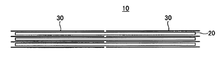
- FIG. 1 is a front view showing an embodiment of a glass packaging structure according to the present invention.
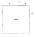
- FIG. 2 is a plan view of the glass packaging structure according to the present invention as viewed from above.
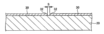
- FIG. 3 is an enlarged longitudinal sectional view showing a state in which a buffer material is interposed between the laminated surfaces of the laminated glasses.
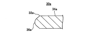
- FIG. 4A is an enlarged longitudinal sectional view showing an end portion of the cushioning material of the first modification.
- FIG. 4B is a longitudinal sectional view showing, in an enlarged manner, a state in which the cushioning material of Modification 1 is interposed between the laminated surfaces of the glass.
- FIG. 5A is an enlarged longitudinal sectional view showing an end portion of the cushioning material of the second modification.
- FIG. 5B is an enlarged longitudinal sectional view showing a state in which the cushioning material of Modification 2 is interposed between the laminated surfaces of the glass.
- FIG. 6A is an enlarged longitudinal sectional view showing an end portion of the cushioning material of the third modification.
- FIG. 6B is an enlarged longitudinal sectional view showing a state in which the cushioning material of Modification 3 is interposed between the laminated surfaces of the glasses.
- FIG. 7A is an enlarged longitudinal sectional view showing an end portion of the cushioning material of the fourth modification.
- FIG. 7B is a longitudinal sectional view showing, in an enlarged manner, a state in which the cushioning material of Modification 4 is interposed between the laminated surfaces of the glass.
- FIG. 8 is a plan view of the glass packaging structure of Modification 5 as viewed from above.
- FIG. 9 is an enlarged longitudinal sectional view showing the glass packaging structure of Modification 5.
- FIG. 1 is a front view showing an embodiment of a glass packaging structure according to the present invention.
- FIG. 2 is a plan view of the glass packaging structure according to the present invention as seen from above.
- the glass packing structure 10 is a process of laminating glass substrates 20 formed in a predetermined size (for example, 8th generation size) by a transfer robot.
- N at least two cushioning materials 30 are interposed between the laminated surfaces.
- the contact area with the glass of the buffer material 30 is smaller than the contact area (main plane) of the glass substrate 20.
- the contact area of the cushioning material 30 may be arbitrary.
- the contact size of the buffer material 30 with the glass substrate 20 may be determined to be Amm or less and Bmm or less depending on the number of buffer materials n. .
- the contact dimensions are preferably 0.5 Amm or less for the long side and Bmm or less for the short side, and may be no more than Amm for the short side and 0.5 Bmm or less for the short side.
- the distance S between the end portions 32 of each cushioning material 30 is 0 mm to 20 mm.
- the setting conditions for each buffer material 30 and the interval S are the thicknesses of the plurality of buffer materials 30 based on JIS P 8118 (1998), t 1 to t n (n is the number of buffer materials, and an integer of 2 or more) ),
- t 1 to t n (n is the number of buffer materials, and an integer of 2 or more)
- t max the maximum value among the thicknesses t 1 to t n of the plurality of cushioning materials
- the minimum value is t min ,
- both the two formulas (A) and (B) are satisfied, and the distance S between the end portions 32 of the adjacent cushioning materials 30 is set to 0 to 20 mm.
- the coefficient on the tmax side is larger than 0.12, the thickest paper protrudes, pressure is concentrated on the edge portion, and it becomes difficult to remove stains.
- the coefficient on the t min side is larger than 0.12, pressure is concentrated on the edge of the paper that becomes the thinnest paper, and it becomes difficult to remove the stain.
- each buffer material 30 can be arranged on the laminated surface of the glass substrate 20 so that the end portions 32 of the adjacent buffer materials 30 are not separated more than necessary. It becomes possible. Therefore, in the step of laminating the glass substrates 20, the load of the upper glass substrate 20 is dispersed on the plane of each buffer material 30. Thereby, the glass substrate 20 is prevented from being damaged or soiled on the laminated surface with which the end portions 32 of the buffer material 30 are in contact, and can prevent the glass substrates from contacting each other.
- the thickness of the end 32 of the buffer material 30 in contact with the glass substrate 20 is made thinner than the thickness of the buffer material 30 measured based on JIS P8118.
- the tip can be made thin by pressurizing the end portion 32 of the cushioning material 30 with a roller or the like.
- FIG. 4A is an enlarged longitudinal sectional view showing an end portion of the cushioning material of the first modification.
- FIG. 4B is a longitudinal sectional view showing, in an enlarged manner, a state in which the cushioning material of Modification 1 is interposed between the laminated surfaces of the glass.
- the end portion 32a of the cushioning material 30a has a curved surface 36a that is curved in a direction of 90 ° or more with respect to the contact surface 34a in contact with the glass substrate 20 by polishing or pressing.
- the two cushioning materials 30a are arranged on the glass substrate 20 so that the end portions 32a face each other with a certain distance S therebetween.
- the curved surface 36a is formed at the end portion 32a of the buffer material 30a, the load of the glass substrate 20 is not concentrated on the corner portion of the end portion 32a of the buffer material 30a, and the curved surface of each buffer material 30a. 36a. Thereby, the glass substrate 20 is prevented from being damaged by the end portion 32a of the buffer material 30a and from being attached to the glass substrate 20 with dirt.
- the setting conditions are set so that both the expressions (A) and (B) are satisfied, and the interval S between the curved surfaces 36a of the neighboring cushioning materials 30a is set to 0 to 20 mm.
- FIG. 5A is an enlarged longitudinal sectional view showing an end portion of the cushioning material of the second modification.
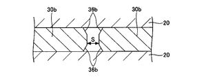
- FIG. 5B is an enlarged longitudinal sectional view showing a state in which the cushioning material of Modification 2 is interposed between the laminated surfaces of the glass.
- the end portion 32b of the cushioning material 30b is provided with a chamfer 36b at a corner portion.
- the two cushioning materials 30b are arranged on the glass substrate 20 so that the end portions 32b face each other with a certain distance S therebetween.
- the chamfer 36b is provided at the corner of the end portion 32b of the buffer material 30b, the load of the glass substrate 20 is not concentrated on the corner portion of the end portion 32b of the buffer material 30b, and each buffer material Dispersed in the chamfer 36b of 30b. As a result, the glass substrate 20 is prevented from being damaged by the end portion 32b of the buffer material 30b and from being contaminated with the glass substrate 20.
- the setting conditions are set so that both the expressions (A) and (B) are satisfied, and the interval S between the end portions 32b of the adjacent buffer materials 30b is set to 0 to 20 mm.
- FIG. 6A is an enlarged longitudinal sectional view showing an end portion of the cushioning material of the third modification.
- FIG. 6B is an enlarged longitudinal sectional view showing a state in which the cushioning material of Modification 3 is interposed between the laminated surfaces of the glasses.
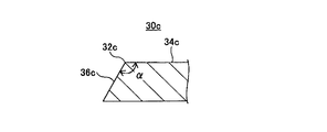
- the end portion 32c of the cushioning material 30c is provided with an inclined surface 36c.
- the two cushioning materials 30c are arranged on the glass substrate 20 so that the end portions 36c face each other with a constant interval S therebetween.
- the inclined surface 36c is provided at the end portion 32c of the buffer material 30c, the load of the glass substrate 20 is not concentrated on the corner portion of the end portion 32c of the buffer material 30c, and each buffer material 30c Dispersed in the plane and the inclined surface 36c. As a result, the glass substrate 20 is prevented from being damaged by the end portion 32c of the cushioning material 30c and from being contaminated with the glass substrate 20.
- the setting condition is set so that both the expressions (A) and (B) are satisfied, and the interval S between the tips of the inclined surfaces 36c of the adjacent cushioning materials 30c is set to 0 to 20 mm. .
- FIG. 7A is an enlarged longitudinal sectional view showing an end portion of the cushioning material of the fourth modification.
- FIG. 7B is a longitudinal sectional view showing, in an enlarged manner, a state in which the cushioning material of Modification 4 is interposed between the glass lamination surfaces.
- the end portion 32d of the cushioning material 30d is provided with a first inclined surface 36d and a second inclined surface 38d.
- the two cushioning materials 30d are arranged on the glass substrate 20 so that the end portions 36d face each other.
- the first inclined surface 36d and the second inclined surface 38d are provided at the end portion 32d of the buffer material 30d, the load of the glass substrate 20 is concentrated on the corner portion of the end portion 32d of the buffer material 30d. Without being distributed, the first inclined surface 36d and the second inclined surface 38d of each buffer material 30d are dispersed. As a result, the glass substrate 20 is prevented from being damaged by the end portion 32d of the buffer material 30d and from being contaminated with the glass substrate 20.
- the setting conditions satisfy both the expressions (A) and (B), and the interval S between the tips of the first sloped surface 36d and the second sloped surface 38d of the adjacent cushioning materials 30b is 0 to It is set to be 20 mm.
- the end portions 32a to 32d of the cushioning materials 30a to 30d may be crushed with a pressure member such as a roller, or a cutting jig (cutter). Etc.) is exemplified by a method of cutting obliquely. Further, when the buffer materials 30a to 30d are plastic films, the end portions 32a to 32d can be curved by heating and expanding.
- FIG. 8 is a plan view of the glass packaging structure of Modification 5 as viewed from above.
- FIG. 9 is an enlarged longitudinal sectional view showing the glass packaging structure of Modification 5.
- the glass packaging structure 40 is configured to interpose two cushioning materials 30 e and 30 f having different sizes between the laminated surfaces of the glass substrates 20 in the step of laminating the glass substrates 20.
- the buffer materials 30e and 30f those having an area smaller than the area of the laminated surface of the glass substrate 20 are used.
- the short side length L1 of the first buffer material 30e is shorter than that of the second buffer material 30f. It is smaller than the side length L2 (L1 ⁇ L2).
- the short side length L1 of the first cushioning material 30e is equal to or less than half of the total width L when the two cushioning materials 30e and 30f are arranged (L1 ⁇ L / 2), and the second cushioning material 30f.
- the short side length L2 is cut to be half or more of L (L2 ⁇ L / 2).
- the difference between L1 and L2 is preferably 1 mm or more, more preferably 20 mm or more, and still more preferably 40 mm or more.
- the interval S between the adjacent end portions 32 is X1 direction from the center line O of the glass substrate 20. It is located in the place shifted to. In this way, the end portions 32 adjacent to each other with the interval S are called a butt portion between the end portions of the cushioning material.
- the shape of the end portion 32 of the above-described modified examples 1 to 4 may be used as appropriate.
- the two cushioning materials 30e and 30f placed between the glass substrate 20-1 and the glass substrate 20-2 are the first cushioning materials.
- 30e is arranged on the left side in FIG. 9, and the second cushioning material 30f is arranged on the right side in FIG.
- the interval S between the adjacent end portions 32 is located at a position shifted in the X1 direction from the center line O of the glass substrate 20.
- the two cushioning materials 30e and 30f placed between the glass substrate 20-2 and the glass substrate 20-3 are arranged such that the first cushioning material 30e is arranged on the right side in FIG. 30f is arranged on the left side in FIG.
- the interval S between the adjacent end portions 32 is located at a position shifted in the X2 direction from the center line O of the glass substrate 20.
- the position of the interval S between the end portions 32 is shifted to the left side or the right side of the center line O of the glass substrate 20.
- a part of the cushioning material is provided with a hollow portion, or in order to simplify disposal of the cushioning material after removal, a part of the cushioning material is used. Perforations may be provided.
- the packaging structure in the case of laminating a large number of glass substrates used in a thin display device has been described.
- the present invention is not limited to this, and also in the case of laminating glass formed in a plate shape other than a glass substrate. Needless to say, the present invention can be applied.
- Glass packaging structure 20 Glass substrate 30, 30a-30f Buffer material 32, 32a-32d End 34a-34d Contact surface 36a Curved surface 36b Chamfer 36c Inclined surface 36d First inclined surface 38d Second inclined surface
Landscapes
- Engineering & Computer Science (AREA)
- Mechanical Engineering (AREA)
- Life Sciences & Earth Sciences (AREA)
- Wood Science & Technology (AREA)
- Buffer Packaging (AREA)
- Packaging Frangible Articles (AREA)
- Laminated Bodies (AREA)
Abstract
Description
(1)本発明は、積層された板状の複数のガラスと、各ガラスの積層面間に複数枚挿入されたシート状の緩衝材と、を有するガラス梱包構造であって、
前記緩衝材は、前記ガラスの積層面よりも小さい面積を有し、複数の緩衝材は、隣り合う緩衝材の各端部が重ならないように配置し、
前記複数の緩衝材のJIS P 8118に基づく厚さをそれぞれt1~tn(nは緩衝材の枚数であり、2以上の整数)、前記n枚の緩衝材の厚さ算術平均値をtave、前記複数の緩衝材の厚さt1~tnのうち最大値をtmax、最小値をtminとするとき、


隣り合う緩衝材の端部同士の間隔が、0~20mmである。
(2)前記緩衝材の前記ガラスに接する端部の先端の厚さが、JIS P 8118に基づき測定された前記緩衝材の厚さよりも薄い。
(3)前記緩衝材の端部は、前記ガラスに接する接触面に対して90°以上の方向に湾曲する曲面が形成される。
(4)前記緩衝材の端部は、前記ガラスに接する接触面に対して90°以上の方向に傾斜する傾斜面が形成される。
(5)前記緩衝材の端部は、角部が前記ガラスに接する接触面に対して90°以上の方向に傾斜するように面取りされている。
(6)各緩衝材の端部同士の突き合わせ部は、隣り合う各ガラスの積層面に対して異なる位置に形成されるようにずらした。
(7)前記緩衝材は、紙または樹脂フィルムにより形成される。
(8)本発明は、積層された板状の複数のガラスと、各ガラスの積層面間に複数枚挿入されたシート状の緩衝材と、を有するガラス梱包方法であって、
前記緩衝材は、前記ガラスの積層面よりも小さい面積を有し、複数の緩衝材は、隣り合う緩衝材の各端部が重ならないように配置し、
前記複数の緩衝材のJIS P 8118に基づく厚さをそれぞれt1~tn(nは緩衝材の枚数であり、2以上の整数)、前記n枚の緩衝材の厚さ算術平均値をtave、前記複数の緩衝材の厚さt1~tnのうち最大値をtmax、最小値をtminとするとき、


隣り合う緩衝材の端部同士の間隔が、0~20mmである。
(9)前記緩衝材の前記ガラスに接する端部の先端の厚さが、JIS P 8118に基づき測定された前記緩衝材の厚さよりも薄い。
(10)前記緩衝材は、紙または樹脂フィルムにより形成される。
(11)前記緩衝材の端部は、角部が前記ガラスに接する接触面に対して90°以上の方向に傾斜面または曲面が形成されるように予め加工されている。
(12)各緩衝材の端部同士の突き合わせ部は、隣り合う各ガラスの積層面に対して異なる位置に形成されるようにずらした。


図4Aは、変形例1の緩衝材の端部を拡大して示す縦断面図である。図4Bは、変形例1の緩衝材をガラスの積層面間に介在させた状態を拡大して示す縦断面図である。
図5Aは、変形例2の緩衝材の端部を拡大して示す縦断面図である。図5Bは、変形例2の緩衝材をガラスの積層面間に介在させた状態を拡大して示す縦断面図である。
図6Aは、変形例3の緩衝材の端部を拡大して示す縦断面図である。図6Bは、変形例3の緩衝材をガラスの積層面間に介在させた状態を拡大して示す縦断面図である。
図7Aは、変形例4の緩衝材の端部を拡大して示す縦断面図である。図7Bは、変形例4の緩衝材をガラスの積層面間に介在させた状態を拡大して示す縦断面図である。
図8は、変形例5のガラス梱包構造を上方からみた平面図である。図9は、変形例5のガラス梱包構造を拡大して示す縦断面図である。
本出願は、2010年7月8日出願の日本特許出願2010-155924に基づくものであり、その内容はここに参照として取り込まれる。
20 ガラス基板
30、30a~30f 緩衝材
32、32a~32d 端部
34a~34d 接触面
36a 曲面
36b 面取り
36c 傾斜面
36d 第1傾斜面
38d 第2傾斜面
Claims (12)
- 積層された板状の複数のガラスと、各ガラスの積層面間に複数枚挿入されたシート状の緩衝材と、を有するガラス梱包構造であって、
前記緩衝材は、前記ガラスの積層面よりも小さい面積を有し、複数の緩衝材は、隣り合う緩衝材の各端部が重ならないように配置し、
前記複数の緩衝材のJIS P 8118に基づく厚さをそれぞれt1~tn(nは緩衝材の枚数であり、2以上の整数)、前記n枚の緩衝材の厚さ算術平均値をtave、前記複数の緩衝材の厚さt1~tnのうち最大値をtmax、最小値をtminとするとき、


隣り合う緩衝材の端部同士の間隔が、0~20mmであるガラス梱包構造。 - 前記緩衝材の前記ガラスに接する端部の先端の厚さが、JIS P 8118に基づき測定された前記緩衝材の厚さよりも薄い請求項1に記載のガラス梱包構造。
- 前記緩衝材の端部は、前記ガラスに接する接触面に対して90°以上の方向に湾曲する曲面が形成される請求項1または2に記載のガラス梱包構造。
- 前記緩衝材の端部は、前記ガラスに接する接触面に対して90°以上の方向に傾斜する傾斜面が形成される請求項1または2に記載のガラス梱包構造。
- 前記緩衝材の端部は、角部が前記ガラスに接する接触面に対して90°以上の方向に傾斜するように面取りされている請求項1または2に記載のガラス梱包構造。
- 各緩衝材の端部同士の突き合わせ部は、隣り合う各ガラスの積層面に対して異なる位置に形成されるようにずらした請求項1乃至5の何れか一項に記載のガラス梱包構造。
- 前記緩衝材は、紙または樹脂フィルムにより形成される請求項1乃至6の何れか一項に記載のガラス梱包構造。
- 積層された板状の複数のガラスと、各ガラスの積層面間に複数枚挿入されたシート状の緩衝材と、を有するガラス梱包方法であって、
前記緩衝材は、前記ガラスの積層面よりも小さい面積を有し、複数の緩衝材は、隣り合う緩衝材の各端部が重ならないように配置し、
前記複数の緩衝材のJIS P 8118に基づく厚さをそれぞれt1~tn(nは緩衝材の枚数であり、2以上の整数)、前記n枚の緩衝材の厚さ算術平均値をtave、前記複数の緩衝材の厚さt1~tnのうち最大値をtmax、最小値をtminとするとき、


隣り合う緩衝材の端部同士の間隔が、0~20mmであるガラス梱包方法。 - 前記緩衝材の前記ガラスに接する端部の先端の厚さが、JIS P 8118に基づき測定された前記緩衝材の厚さよりも薄い請求項8に記載のガラス梱包方法。
- 前記緩衝材は、紙または樹脂フィルムにより形成される請求項8または9に記載のガラス梱包方法。
- 前記緩衝材の端部は、角部が前記ガラスに接する接触面に対して90°以上の方向に傾斜面または曲面が形成されるように予め加工されている請求項8または9に記載のガラス梱包方法。
- 各緩衝材の端部同士の突き合わせ部は、隣り合う各ガラスの積層面に対して異なる位置に形成されるようにずらした請求項8乃至11の何れか一項に記載のガラス梱包方法。
Priority Applications (3)
| Application Number | Priority Date | Filing Date | Title |
|---|---|---|---|
| KR1020137000461A KR20130112852A (ko) | 2010-07-08 | 2011-06-29 | 유리 곤포 구조 및 유리 곤포 방법 |
| JP2012523831A JPWO2012005155A1 (ja) | 2010-07-08 | 2011-06-29 | ガラス梱包構造及びガラス梱包方法 |
| CN2011800338900A CN102985338A (zh) | 2010-07-08 | 2011-06-29 | 玻璃包装结构及玻璃包装方法 |
Applications Claiming Priority (2)
| Application Number | Priority Date | Filing Date | Title |
|---|---|---|---|
| JP2010-155924 | 2010-07-08 | ||
| JP2010155924 | 2010-07-08 |
Publications (1)
| Publication Number | Publication Date |
|---|---|
| WO2012005155A1 true WO2012005155A1 (ja) | 2012-01-12 |
Family
ID=45441137
Family Applications (1)
| Application Number | Title | Priority Date | Filing Date |
|---|---|---|---|
| PCT/JP2011/064948 Ceased WO2012005155A1 (ja) | 2010-07-08 | 2011-06-29 | ガラス梱包構造及びガラス梱包方法 |
Country Status (5)
| Country | Link |
|---|---|
| JP (1) | JPWO2012005155A1 (ja) |
| KR (1) | KR20130112852A (ja) |
| CN (1) | CN102985338A (ja) |
| TW (1) | TW201217238A (ja) |
| WO (1) | WO2012005155A1 (ja) |
Cited By (2)
| Publication number | Priority date | Publication date | Assignee | Title |
|---|---|---|---|---|
| JP2015131684A (ja) * | 2014-01-09 | 2015-07-23 | コーニング精密素材株式会社Corning Precision Materials Co., Ltd. | ガラス基板の包装方法 |
| WO2018221358A1 (ja) * | 2017-05-29 | 2018-12-06 | Agc株式会社 | ガラス板梱包体の製造方法、及びガラス板梱包体 |
Families Citing this family (1)
| Publication number | Priority date | Publication date | Assignee | Title |
|---|---|---|---|---|
| KR102051924B1 (ko) | 2015-11-30 | 2019-12-04 | 주식회사 엘지화학 | 다수의 배터리 팩 시스템의 마스터 bms 및 슬레이브 bms 인식 방법 |
Citations (6)
| Publication number | Priority date | Publication date | Assignee | Title |
|---|---|---|---|---|
| JPH07883U (ja) * | 1993-06-02 | 1995-01-06 | 旭硝子株式会社 | ガラス板積層用スペーサ |
| JP2001315964A (ja) * | 2000-05-11 | 2001-11-13 | Nisseki Kosan Kk | 板材用スペーサに用いる仮付けパッドおよび板材用スペーサ |
| JP2003327267A (ja) * | 2002-05-07 | 2003-11-19 | Yoshiharu Horikiri | ガラス板用緩衝材及びその製造方法 |
| JP2006327640A (ja) * | 2005-05-27 | 2006-12-07 | Dainippon Printing Co Ltd | 基板収納容器及び基板収納体 |
| JP2007262409A (ja) * | 2007-04-02 | 2007-10-11 | Jsp Corp | ガラス基板用間紙 |
| JP2009184704A (ja) * | 2008-02-06 | 2009-08-20 | Daio Paper Corp | ガラス用合紙 |
Family Cites Families (4)
| Publication number | Priority date | Publication date | Assignee | Title |
|---|---|---|---|---|
| JP2006160271A (ja) * | 2004-12-02 | 2006-06-22 | Nippon Electric Glass Co Ltd | ガラス板の梱包スペーサ及びこれを用いた梱包ユニット |
| JP2006290382A (ja) * | 2005-04-07 | 2006-10-26 | Paachi:Kk | ガラス板用緩衝材 |
| CN2923568Y (zh) * | 2006-07-21 | 2007-07-18 | 山汰科技企业有限公司 | 间隔物 |
| CN200971213Y (zh) * | 2006-11-10 | 2007-11-07 | 山汰科技企业有限公司 | 间隔物 |
-
2011
- 2011-06-29 JP JP2012523831A patent/JPWO2012005155A1/ja not_active Withdrawn
- 2011-06-29 CN CN2011800338900A patent/CN102985338A/zh active Pending
- 2011-06-29 KR KR1020137000461A patent/KR20130112852A/ko not_active Withdrawn
- 2011-06-29 WO PCT/JP2011/064948 patent/WO2012005155A1/ja not_active Ceased
- 2011-07-08 TW TW100124304A patent/TW201217238A/zh unknown
Patent Citations (6)
| Publication number | Priority date | Publication date | Assignee | Title |
|---|---|---|---|---|
| JPH07883U (ja) * | 1993-06-02 | 1995-01-06 | 旭硝子株式会社 | ガラス板積層用スペーサ |
| JP2001315964A (ja) * | 2000-05-11 | 2001-11-13 | Nisseki Kosan Kk | 板材用スペーサに用いる仮付けパッドおよび板材用スペーサ |
| JP2003327267A (ja) * | 2002-05-07 | 2003-11-19 | Yoshiharu Horikiri | ガラス板用緩衝材及びその製造方法 |
| JP2006327640A (ja) * | 2005-05-27 | 2006-12-07 | Dainippon Printing Co Ltd | 基板収納容器及び基板収納体 |
| JP2007262409A (ja) * | 2007-04-02 | 2007-10-11 | Jsp Corp | ガラス基板用間紙 |
| JP2009184704A (ja) * | 2008-02-06 | 2009-08-20 | Daio Paper Corp | ガラス用合紙 |
Cited By (4)
| Publication number | Priority date | Publication date | Assignee | Title |
|---|---|---|---|---|
| JP2015131684A (ja) * | 2014-01-09 | 2015-07-23 | コーニング精密素材株式会社Corning Precision Materials Co., Ltd. | ガラス基板の包装方法 |
| WO2018221358A1 (ja) * | 2017-05-29 | 2018-12-06 | Agc株式会社 | ガラス板梱包体の製造方法、及びガラス板梱包体 |
| JPWO2018221358A1 (ja) * | 2017-05-29 | 2020-04-02 | Agc株式会社 | ガラス板梱包体の製造方法、及びガラス板梱包体 |
| JP7088180B2 (ja) | 2017-05-29 | 2022-06-21 | Agc株式会社 | ガラス板梱包体の製造方法 |
Also Published As
| Publication number | Publication date |
|---|---|
| JPWO2012005155A1 (ja) | 2013-09-02 |
| CN102985338A (zh) | 2013-03-20 |
| KR20130112852A (ko) | 2013-10-14 |
| TW201217238A (en) | 2012-05-01 |
Similar Documents
| Publication | Publication Date | Title |
|---|---|---|
| CN102639419B (zh) | 片材处理装置及装备有片材处理装置的成像装置 | |
| JP5610261B2 (ja) | ガラス板積層体 | |
| CN103402892B (zh) | 玻璃板层叠体及玻璃板的取出方法 | |
| KR102539551B1 (ko) | 유리 합지, 유리판 곤포체, 유리 합지 적층 방법 및 유리 합지 적층 장치 | |
| TWI478851B (zh) | Glass plate packing device | |
| TW201406550A (zh) | 玻璃板積層體之積層方法及玻璃板積層體與玻璃板捆包體 | |
| WO2009110552A1 (ja) | 非接触搬送装置 | |
| WO2014162953A1 (ja) | 板状体の梱包体 | |
| KR20150026908A (ko) | 필름 적층체의 제조 방법 및 필름 적층체의 제조 설비 | |
| TW201536569A (zh) | 部件製造方法、部件製造裝置以及部件 | |
| JPWO2012005155A1 (ja) | ガラス梱包構造及びガラス梱包方法 | |
| CN108698752B (zh) | 附有保护薄膜的玻璃板及其制造方法、以及捆包体 | |
| JP6163377B2 (ja) | フィルム積層体からの異物除去方法、フィルム積層体の製造方法及び製造装置。 | |
| JP4228326B2 (ja) | ガラス板の収納方法 | |
| CN217171721U (zh) | 玻璃板捆包体 | |
| CN104773390A (zh) | 缓冲包材结构 | |
| TWI734822B (zh) | 玻璃板用托架及玻璃板捆包體 | |
| JP6683798B1 (ja) | 偏光板積層体、及び、偏光板の積層方法 | |
| JP2016034843A (ja) | ガラス板用合紙及び合紙付きガラス板並びにガラス板梱包体 | |
| CN119095777A (zh) | 玻璃板捆包体 | |
| JP7470293B2 (ja) | ガラス板梱包用パレット及びガラス板梱包体 | |
| CN114206740B (zh) | 玻璃板捆包体以及玻璃板捆包体的制作方法 | |
| JP3102996U (ja) | 液晶表示基盤等の半製品用の保護材 | |
| TW201425147A (zh) | 玻璃板捆包用棧板 | |
| JPH11100087A (ja) | 平面表示基板の搬送方法 |
Legal Events
| Date | Code | Title | Description |
|---|---|---|---|
| WWE | Wipo information: entry into national phase |
Ref document number: 201180033890.0 Country of ref document: CN |
|
| 121 | Ep: the epo has been informed by wipo that ep was designated in this application |
Ref document number: 11803489 Country of ref document: EP Kind code of ref document: A1 |
|
| WWE | Wipo information: entry into national phase |
Ref document number: 2012523831 Country of ref document: JP |
|
| ENP | Entry into the national phase |
Ref document number: 20137000461 Country of ref document: KR Kind code of ref document: A |
|
| NENP | Non-entry into the national phase |
Ref country code: DE |
|
| 122 | Ep: pct application non-entry in european phase |
Ref document number: 11803489 Country of ref document: EP Kind code of ref document: A1 |