WO2011162017A1 - 車両用シートの組み付け構造 - Google Patents
車両用シートの組み付け構造 Download PDFInfo
- Publication number
- WO2011162017A1 WO2011162017A1 PCT/JP2011/059699 JP2011059699W WO2011162017A1 WO 2011162017 A1 WO2011162017 A1 WO 2011162017A1 JP 2011059699 W JP2011059699 W JP 2011059699W WO 2011162017 A1 WO2011162017 A1 WO 2011162017A1
- Authority
- WO
- WIPO (PCT)
- Prior art keywords
- wall
- leg
- bush
- seat
- bolt
- Prior art date
Links
Images


Classifications
-
- B—PERFORMING OPERATIONS; TRANSPORTING
- B60—VEHICLES IN GENERAL
- B60N—SEATS SPECIALLY ADAPTED FOR VEHICLES; VEHICLE PASSENGER ACCOMMODATION NOT OTHERWISE PROVIDED FOR
- B60N2/00—Seats specially adapted for vehicles; Arrangement or mounting of seats in vehicles
- B60N2/005—Arrangement or mounting of seats in vehicles, e.g. dismountable auxiliary seats
- B60N2/015—Attaching seats directly to vehicle chassis
-
- B—PERFORMING OPERATIONS; TRANSPORTING
- B60—VEHICLES IN GENERAL
- B60N—SEATS SPECIALLY ADAPTED FOR VEHICLES; VEHICLE PASSENGER ACCOMMODATION NOT OTHERWISE PROVIDED FOR
- B60N2/00—Seats specially adapted for vehicles; Arrangement or mounting of seats in vehicles
- B60N2/68—Seat frames
- B60N2/682—Joining means
Definitions
- the present invention relates to a vehicle seat assembly structure.
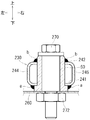
- FIGS. 7 to 9 it is fastened to the seat cushion 202 side, and is formed in a substantially rectangular tube shape from the first wall 240, the second wall 242, the third wall 244 and the fourth wall 246.
- the first wall 240 facing the vehicle floor 260 and the second wall 242 facing the first wall 240 connect the bolt 270 and the nut 272 to the vehicle floor 260.
- An assembly structure of a vehicular seat (for example, a right rear seat of a one-box type vehicle type) 201 that is fastened together is already known.
- a substantially cylindrical metal bush 250 is disposed so that a bolt 270 can be inserted. Thereby, even if the bolt 270 and the nut 272 are strongly tightened, the leg 230 can be prevented from being crushed, so that the assembly strength of the vehicle seat 201 can be improved.
- Patent Document 1 JP 2006-315540 A
- the bush 250 is disposed so as to penetrate the leg 230 in the insertion direction of the bolt 270. Therefore, the two welded portions (the one end side in the axial direction of the bush 250 and the first wall 240 of the leg 230 and the other end side in the axial direction of the bush 250) that fix the bush 250 to the leg 230. And the second wall 242 of the leg 230. In FIGS. 8 and 9, the latter welded portion (b) in FIGS. The appearance of assembling the sheet 201 was poor.
- the present invention is intended to solve such a problem.
- the purpose of the present invention is to improve the appearance of a vehicle seat when the vehicle seat is assembled to the vehicle floor by fastening the leg to the vehicle floor with bolts and nuts. It is to provide a structure capable of preventing the leg from being crushed without deteriorating.
- the present invention relates to a vehicle floor among four walls of a leg fastened to the seat cushion side and formed in a substantially rectangular tube shape from the first wall, the second wall, the third wall, and the fourth wall.
- the first wall facing each other and the second wall facing the first wall are fastened together with bolts and nuts to the vehicle floor to prevent the legs from being crushed by the joint fastening.
- the substantially cylindrical bush is an assembly structure of a vehicle seat in which a bolt can be inserted into the leg, and a flange is formed at the edge of one end in the axial direction of the bush.
- the first wall of the leg is sandwiched between the vehicle floor and the second wall of the leg is sandwiched between the head of the bolt and the other end in the axial direction of the bush. .
- the flange of the bush and the first wall of the leg may be joined by welding. According to this structure, the vehicle seat can be assembled to the vehicle floor with the bush fixed to the leg. Therefore, the workability of this assembly can be improved as compared with the case where the fixing is not performed.
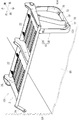
- FIG. 1 is a perspective view showing an assembly structure of a right rear seat according to Embodiment 1 of the present invention.
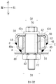
- FIG. 2 is a side view of the main part of FIG. 3 is a cross-sectional view taken along line III-III in FIG.
- FIG. 4 is a perspective view showing the assembly structure of the right rear seat according to the second embodiment of the present invention.
- FIG. 5 is a side view of the main part of FIG. 6 is a cross-sectional view taken along line VI-VI in FIG.
- FIG. 7 is a perspective view showing the assembly structure of the right rear seat according to the prior art.
- Example 1 of the present invention will be described with reference to FIGS. First, a schematic configuration of the right rear seat 1 according to the first embodiment of the present invention will be described with reference to FIG.
- the right rear seat 1 is a seat for two persons that includes a seat cushion 2 and a seat back (not shown). Of the seat cushion 2 and the seat back, the seat cushion 2 will be described in detail.
- the seat back may have a known configuration, a detailed description thereof will be omitted.
- the cushion pad and the seat cover are omitted in order to make the internal structure of the seat cushion of the right rear seat 1 easier to see. The same applies to Example 2 described later.
- the seat cushion 2 includes a cushion frame 10, a known cushion pad (not shown) that is assembled to the cushion frame 10 in a covering manner, and a known seat cover (not shown) that covers the surface of the cushion pad. It is configured.
- the cushion frame 10 mainly includes a frame main body 20 and a leg 30. Hereinafter, the frame body 20 and the leg 30 will be described individually.
- the frame main body 20 is a member for forming a skeleton of the seat cushion 2 and is formed in a rectangular frame shape.
- a plurality of springs 22,... 22 are stretched along the front-rear direction.
- brackets 24 and 26 for assembling the frame body 20 to the inner wall 64 on the right side of the vehicle are fastened to the front and rear ends on the outer side (right side in FIG. 1) of the frame body 20, respectively.
- the leg 30 is a member for assembling the seat cushion 2 to the vehicle floor 60, and is formed to have a substantially U-shape.
- the leg 30 is formed in a substantially rectangular tube shape from the first wall 40, the second wall 42, the third wall 44, and the fourth wall 46 (see FIG. 3).
- base side 32 the side where the free end does not exist (the bottom side in FIG. 1, hereinafter referred to as “base side 32”) passes through the thickness direction.
- the through-holes 40a and 42a are formed so as to form a pair in the front-rear direction.
- the first wall 40 (the lower wall in FIGS. 1 to 3) on the base side 32 is formed with mounting holes 40a, 40a penetrating in the thickness direction so as to form a pair in the front-rear direction.
- the mounting hole 40a is formed so that a bush 50 described later can be inserted.
- the diameter of the mounting hole 40a is denoted as “D1”.
- the second wall 42 (the upper wall in FIGS. 1 to 3) on the base side 32 is formed with mounting holes 42a and 42a penetrating in the thickness direction so as to form a pair in the front-rear direction.
- the mounting hole 42a is formed so that a bolt 70 described later can be inserted.
- the diameter of the mounting hole 42a is denoted as “D2”. Both the mounting holes 40a and 42a are formed so that their axial centers coincide with each other.
- the bush 50 is a metal member formed in a cylindrical shape having an insertion hole 52 into which the bolt 70 can be inserted.
- a flange 54 is formed at the edge of one end (the lower end in FIGS. 2 to 3) of the bush 50 in the axial direction.
- the axial length of the bush 50 is the other end side in the axial direction of the bush 50 (the upper end side in FIGS. 2 to 3) so that the flange 54 is caught by the edge of the mounting hole 40a, and the flange 54 is formed.
- the other side When the other side is inserted through the mounting hole 40a of the leg 30, the other end can be brought into contact with the inner surface of the second wall 42 of the leg 30 (the edge of the mounting hole 42a). Is set. Thereby, even if the bolt 70 is inserted into the insertion hole 52 of the bush 50 and the inserted bolt 70 and the nut 72 are strongly tightened, the leg 30 can be prevented from being crushed.
- the bush 50 is inserted at the other end side in the axial direction of the bush 50 from the mounting hole 40a of the leg 30 so that the flange 54 is hooked on the edge of the mounting hole 40a.
- the flange 54 and the first wall 40 of the leg 30 are joined to each other by welding in a state where they are in contact with the inner surface of the wall 42 (the edge of the mounting hole 42a). 2 to 3, A indicates a welded portion.
- the both right ends of the legs 30 are joined to the front and rear ends on the inner side (right side in FIG. 1) of the frame main body 20, respectively.
- the right rear seat 1 is composed of a seat cushion 2 having a cushion frame 10 composed of the frame body 20 and the leg 30 and a known seat back.
- This predetermined position is a rear portion on the right side inside the passenger compartment.
- both the brackets 24 and 26 of the frame body 20 and the inner wall 64 on the right side of the vehicle are fastened together via bolts and nuts (both not shown), and both the brackets 24 and 26 are attached to the inner wall 64.
- the joint tightening referred to here is to penetrate the bolt through the bracket 24 (26) and the inner wall 64, and to tighten the penetrated bolt with a nut.
- the leg 30 and the vehicle floor 60 are fastened together via bolts 70 and 70 and nuts 72 and 72, and the work of assembling these legs 30 to the vehicle floor 60 is performed. That is, the bolt 70 is penetrated from the attachment hole 42 a of the leg 30 through the attachment hole 40 a and the attachment hole 62 formed in the vehicle floor 60, and the penetrated bolt 70 is nut 72 from the back side of the vehicle floor 60. Perform tightening operation with.
- the assembly structure of the right rear seat 1 according to the first embodiment of the present invention is configured as described above. According to this configuration, when the leg 30 and the vehicle floor 60 are tightened together via the bolt 70 and the nut 72, this tightening force is applied between the second wall 42 of the leg 30, the bush 50, and the vehicle floor 60. Works. As a result, as described in the related art, the leg 30 can be prevented from being crushed even if the bolt 70 and the nut 72 are tightened strongly, so that the assembly strength of the right rear seat 1 can be improved. At this time, since the other end side in the axial direction of the bush 50 is in contact with the inner surface of the second wall 42 of the leg 30 (the edge of the mounting hole 42a), the bush 50 is fixed to the leg 30.
- the welded portion (the welded portion between the one end side in the axial direction of the bush and the first wall of the leg, A in FIGS. 2 to 3) can be completed at only one place. For this reason, as described in the prior art, this welded portion is not exposed, and therefore, the appearance of the right rear seat 1 can be prevented from being deteriorated.
- the flange 54 of the bush 50 and the first wall 40 of the leg 30 are joined by welding. Therefore, the right rear seat 1 can be assembled to the vehicle floor 60 with the bush 50 fixed to the leg 30. Therefore, the workability of the assembly can be improved as compared with the case where the fixing is not performed.
- Example 2 Next, Example 2 of the present invention will be described with reference to FIGS.
- the right rear seat 201 of the second embodiment is a form in which the substantially U-shaped bent portion of the leg 30 is reinforced compared to the right rear seat 1 of the first embodiment already described.
- the configuration excluding this reinforcing configuration is the same as that of the right rear seat 1 of the second embodiment in the right rear seat 201 of the second embodiment. The description to be omitted will be omitted.
- reinforcing covers 134 and 134 are joined to the surface of the second wall 42 at the substantially U-shaped bent portion of the leg 30 of the right rear seat 201 by welding, respectively.
- C indicates a welded portion.
- the assembly structure of the right rear seat 201 according to the second embodiment of the present invention is configured as described above. According to this structure, the same effect as the assembly structure of the right rear seat 1 of Example 1 can be obtained. Moreover, according to this structure, since the reinforcement covers 134 and 134 are provided, the intensity
- the contents described above are only related to one embodiment of the present invention, and do not mean that the present invention is limited to the above contents.
- the “right rear seat 1” of the one-box type vehicle is described as an example of the “vehicle seat”.
- the present invention is not limited to this, and the “left rear seat” may be used. In that case, the arrangement of the brackets 24 and 26 and the leg 30 is reversed left and right.
Abstract
Description
この構造によれば、レッグと車両フロアとをボルトとナットとを介して共締めすると、この締め付け力がレッグの第2の壁とブッシュと車両フロアとの間で作用する。これにより、従来技術で説明したように、ボルトとナットとを強く締め付けてもレッグが潰れることを防止できるため、車両用シートの組み付け強度を向上させることができる。このとき、ブッシュの軸方向における他端側は、レッグの第2の壁の内面に接触した状態となっているため、ブッシュをレッグに固着させている溶接部を1箇所のみで済ませることができる。そのため、従来技術で説明したように、この溶接部が露出してしまうことがなく、したがって、車両用シートの組み付けの見栄えの悪化を防止できる。
この構造によれば、ブッシュをレッグに固着させた状態で、車両用シートを車両フロアに組み付けることができる。そのため、この固着をさせていない場合と比較すると、この組み付けの作業性を向上させることができる。
まず、本発明の実施例1を、図1~3を用いて説明する。はじめに、図1を参照して、本発明の実施例1に係る右後部座席1の概略構成を説明する。この右後部座席1は、シートクッション2と、シートバック(図示しない)とから構成されている、2人掛け用のシートである。これらシートクッション2とシートバックのうち、シートクッション2について詳述していく。
次に、本発明の実施例2を、図4~6を用いて説明する。この実施例2の右後部座席201は、既に説明した実施例1の右後部座席1と比較すると、レッグ30の略コ字状の曲がり部を補強させた形態である。なお、この補強の構成を除いた構成は、実施例2の右後部座席201も実施例1の右後部座席1と同一であるため、図面において、同一部材には、同一符号を付すことで重複する説明は省略することとする。
各実施例では、『車両用シート』の例として、ワンボックスタイプの車種の『右後部座席1』を例に説明した。しかし、これに限定されるものでなく、同『左後部座席』であっても構わない。その場合、両ブラケット24、26およびレッグ30の配置が左右に逆になる。
Claims (2)
- シートクッション側に締結され、第1の壁、第2の壁、第3の壁および第4の壁から略四角筒状に形成されているレッグの4壁のうち、車両フロアと向かい合う第1の壁と、この第1の壁と向かい合う第2の壁とが車両フロアに対してボルトとナットとを介して共締めされており、この共締めによってレッグが潰れることを防止するための略筒状のブッシュがレッグの内部にボルトを差し込み可能に配置されている車両用シートの組み付け構造であって、
ブッシュの軸方向における一端の縁にはフランジが形成されており、
このフランジは、レッグの第1の壁と車両フロアとの間に挟み込まれており、
レッグの第2の壁は、ボルトの頭部とブッシュの軸方向における他端との間に挟み込まれていることを特徴とする車両用シートの組み付け構造。 - 請求項1に記載の車両用シートの組み付け構造であって、
ブッシュのフランジとレッグの第1の壁とは、溶接によって接合されていることを特徴とする車両用シートの組み付け構造。
Priority Applications (4)
| Application Number | Priority Date | Filing Date | Title |
|---|---|---|---|
| CN201180031096.2A CN103025576B (zh) | 2010-06-22 | 2011-04-20 | 车辆座椅安装结构 |
| JP2012521361A JP5490896B2 (ja) | 2010-06-22 | 2011-04-20 | 車両用シートの組み付け構造 |
| EP11797905.4A EP2586653B1 (en) | 2010-06-22 | 2011-04-20 | Vehicle seat mounting structure |
| AU2011270523A AU2011270523B2 (en) | 2010-06-22 | 2011-04-20 | Vehicle seat mounting structure |
Applications Claiming Priority (2)
| Application Number | Priority Date | Filing Date | Title |
|---|---|---|---|
| JP2010141466 | 2010-06-22 | ||
| JP2010-141466 | 2010-06-22 |
Publications (1)
| Publication Number | Publication Date |
|---|---|
| WO2011162017A1 true WO2011162017A1 (ja) | 2011-12-29 |
Family
ID=45371220
Family Applications (1)
| Application Number | Title | Priority Date | Filing Date |
|---|---|---|---|
| PCT/JP2011/059699 WO2011162017A1 (ja) | 2010-06-22 | 2011-04-20 | 車両用シートの組み付け構造 |
Country Status (5)
| Country | Link |
|---|---|
| EP (1) | EP2586653B1 (ja) |
| JP (1) | JP5490896B2 (ja) |
| CN (1) | CN103025576B (ja) |
| AU (1) | AU2011270523B2 (ja) |
| WO (1) | WO2011162017A1 (ja) |
Cited By (2)
| Publication number | Priority date | Publication date | Assignee | Title |
|---|---|---|---|---|
| EP2703289A3 (de) * | 2012-08-31 | 2016-08-10 | Recaro Aircraft Seating GmbH & Co. KG | Sitzteilervorrichtung |
| JP2017094821A (ja) * | 2015-11-20 | 2017-06-01 | トヨタ紡織株式会社 | 乗物用シートフレーム |
Families Citing this family (3)
| Publication number | Priority date | Publication date | Assignee | Title |
|---|---|---|---|---|
| DE102013008299A1 (de) * | 2013-05-15 | 2014-11-20 | Man Truck & Bus Ag | Haltevorrichtung, insbesondere für einen Fahrzeugsitz |
| CN108790986A (zh) * | 2017-05-04 | 2018-11-13 | 江苏卡威汽车工业集团股份有限公司 | 一种二人主座坐垫加强板 |
| PL126744U1 (pl) * | 2017-10-30 | 2019-05-06 | Brodawka Marek Przed Produkcyjno Handlowo Uslugowe Mkm Spolka Cywilna | Podstawa fotela samochodowego |
Citations (3)
| Publication number | Priority date | Publication date | Assignee | Title |
|---|---|---|---|---|
| JPS58171729U (ja) * | 1982-05-14 | 1983-11-16 | 荒川車体工業株式会社 | バス用シ−トレツグ構造 |
| JPH0616073A (ja) * | 1992-06-30 | 1994-01-25 | Suzuki Motor Corp | 子供用シート付自動車シート |
| JP2006315540A (ja) | 2005-05-12 | 2006-11-24 | Honda Motor Co Ltd | 車両用シートの支軸構造 |
Family Cites Families (5)
| Publication number | Priority date | Publication date | Assignee | Title |
|---|---|---|---|---|
| WO2007037374A1 (ja) * | 2005-09-30 | 2007-04-05 | Ts Tech Co., Ltd. | 車両用シートの乗員重量測定装置及び荷重センサの取付構造 |
| JP5055918B2 (ja) * | 2006-09-28 | 2012-10-24 | アイシン精機株式会社 | パワーシートスライド装置 |
| US7729122B2 (en) * | 2006-10-13 | 2010-06-01 | Illinois Tool Works Inc. | Fastener for heat sinks |
| DE102006060829B4 (de) * | 2006-12-22 | 2010-03-25 | Keiper Gmbh & Co. Kg | Lageranordnung, insbesondere eines Fahrzeugsitzes |
| JP5225603B2 (ja) * | 2007-03-30 | 2013-07-03 | 株式会社ブリヂストン | 防振装置 |
-
2011
- 2011-04-20 AU AU2011270523A patent/AU2011270523B2/en not_active Ceased
- 2011-04-20 CN CN201180031096.2A patent/CN103025576B/zh not_active Expired - Fee Related
- 2011-04-20 EP EP11797905.4A patent/EP2586653B1/en not_active Not-in-force
- 2011-04-20 WO PCT/JP2011/059699 patent/WO2011162017A1/ja active Application Filing
- 2011-04-20 JP JP2012521361A patent/JP5490896B2/ja active Active
Patent Citations (3)
| Publication number | Priority date | Publication date | Assignee | Title |
|---|---|---|---|---|
| JPS58171729U (ja) * | 1982-05-14 | 1983-11-16 | 荒川車体工業株式会社 | バス用シ−トレツグ構造 |
| JPH0616073A (ja) * | 1992-06-30 | 1994-01-25 | Suzuki Motor Corp | 子供用シート付自動車シート |
| JP2006315540A (ja) | 2005-05-12 | 2006-11-24 | Honda Motor Co Ltd | 車両用シートの支軸構造 |
Non-Patent Citations (1)
| Title |
|---|
| See also references of EP2586653A4 * |
Cited By (2)
| Publication number | Priority date | Publication date | Assignee | Title |
|---|---|---|---|---|
| EP2703289A3 (de) * | 2012-08-31 | 2016-08-10 | Recaro Aircraft Seating GmbH & Co. KG | Sitzteilervorrichtung |
| JP2017094821A (ja) * | 2015-11-20 | 2017-06-01 | トヨタ紡織株式会社 | 乗物用シートフレーム |
Also Published As
| Publication number | Publication date |
|---|---|
| CN103025576B (zh) | 2015-04-29 |
| EP2586653A4 (en) | 2013-10-30 |
| EP2586653A1 (en) | 2013-05-01 |
| EP2586653B1 (en) | 2014-10-22 |
| JP5490896B2 (ja) | 2014-05-14 |
| AU2011270523B2 (en) | 2014-03-20 |
| CN103025576A (zh) | 2013-04-03 |
| JPWO2011162017A1 (ja) | 2013-08-19 |
| AU2011270523A1 (en) | 2013-01-10 |
Similar Documents
| Publication | Publication Date | Title |
|---|---|---|
| JP5640934B2 (ja) | 車両の前部車体構造 | |
| JP5490896B2 (ja) | 車両用シートの組み付け構造 | |
| CN109955920B (zh) | 车身后部构造 | |
| JP4910882B2 (ja) | サスクロスメンバ取付け構造 | |
| JP2012030632A (ja) | 車両用シート | |
| JP6011456B2 (ja) | アームレスト取付構造 | |
| JP5906707B2 (ja) | 車両用シートのシートフレーム構造 | |
| JP5278135B2 (ja) | 車両搭載物締結構造 | |
| US10821867B2 (en) | Headrest support device | |
| US10556528B2 (en) | Cushion frame | |
| JP5297054B2 (ja) | 車両用シート | |
| WO2021060342A1 (ja) | 車両のフロア構造 | |
| JP2000344160A (ja) | 車両用部品の取付構造 | |
| JP2019202673A (ja) | 乗物用シート | |
| JP2015123848A (ja) | 車体構造 | |
| JP5397603B2 (ja) | マフラー支持構造 | |
| KR100380490B1 (ko) | 자동차용 브라켓 어셈블리 | |
| JP2023061184A (ja) | 支持部材組付構造 | |
| JP2006143155A (ja) | 車両の後部車体構造 | |
| JP2004268810A (ja) | シート取付け装置 | |
| JP2021109474A (ja) | 乗物用シート | |
| JP2015085830A (ja) | 車両用シートのフレーム構造 | |
| JP2020185849A (ja) | 乗物用シート | |
| JP4301129B2 (ja) | デッキクロスメンバ取付構造 | |
| JP2020011622A (ja) | 乗物用シート |
Legal Events
| Date | Code | Title | Description |
|---|---|---|---|
| WWE | Wipo information: entry into national phase |
Ref document number: 201180031096.2 Country of ref document: CN |
|
| 121 | Ep: the epo has been informed by wipo that ep was designated in this application |
Ref document number: 11797905 Country of ref document: EP Kind code of ref document: A1 |
|
| WWE | Wipo information: entry into national phase |
Ref document number: 2012521361 Country of ref document: JP |
|
| WWE | Wipo information: entry into national phase |
Ref document number: 1201006631 Country of ref document: TH |
|
| NENP | Non-entry into the national phase |
Ref country code: DE |
|
| WWE | Wipo information: entry into national phase |
Ref document number: 2011797905 Country of ref document: EP |
|
| ENP | Entry into the national phase |
Ref document number: 2011270523 Country of ref document: AU Date of ref document: 20110420 Kind code of ref document: A |