WO2011145673A1 - ブレーキ装置 - Google Patents
ブレーキ装置 Download PDFInfo
- Publication number
- WO2011145673A1 WO2011145673A1 PCT/JP2011/061484 JP2011061484W WO2011145673A1 WO 2011145673 A1 WO2011145673 A1 WO 2011145673A1 JP 2011061484 W JP2011061484 W JP 2011061484W WO 2011145673 A1 WO2011145673 A1 WO 2011145673A1
- Authority
- WO
- WIPO (PCT)
- Prior art keywords
- pressure
- path
- hydraulic pressure
- control valve
- chamber
- Prior art date
- Legal status (The legal status is an assumption and is not a legal conclusion. Google has not performed a legal analysis and makes no representation as to the accuracy of the status listed.)
- Ceased
Links
Images




Classifications
-
- B—PERFORMING OPERATIONS; TRANSPORTING
- B60—VEHICLES IN GENERAL
- B60T—VEHICLE BRAKE CONTROL SYSTEMS OR PARTS THEREOF; BRAKE CONTROL SYSTEMS OR PARTS THEREOF, IN GENERAL; ARRANGEMENT OF BRAKING ELEMENTS ON VEHICLES IN GENERAL; PORTABLE DEVICES FOR PREVENTING UNWANTED MOVEMENT OF VEHICLES; VEHICLE MODIFICATIONS TO FACILITATE COOLING OF BRAKES
- B60T7/00—Brake-action initiating means
- B60T7/02—Brake-action initiating means for personal initiation
- B60T7/04—Brake-action initiating means for personal initiation foot actuated
- B60T7/042—Brake-action initiating means for personal initiation foot actuated by electrical means, e.g. using travel or force sensors
-
- B—PERFORMING OPERATIONS; TRANSPORTING
- B60—VEHICLES IN GENERAL
- B60T—VEHICLE BRAKE CONTROL SYSTEMS OR PARTS THEREOF; BRAKE CONTROL SYSTEMS OR PARTS THEREOF, IN GENERAL; ARRANGEMENT OF BRAKING ELEMENTS ON VEHICLES IN GENERAL; PORTABLE DEVICES FOR PREVENTING UNWANTED MOVEMENT OF VEHICLES; VEHICLE MODIFICATIONS TO FACILITATE COOLING OF BRAKES
- B60T13/00—Transmitting braking action from initiating means to ultimate brake actuator with power assistance or drive; Brake systems incorporating such transmitting means, e.g. air-pressure brake systems
- B60T13/10—Transmitting braking action from initiating means to ultimate brake actuator with power assistance or drive; Brake systems incorporating such transmitting means, e.g. air-pressure brake systems with fluid assistance, drive, or release
- B60T13/12—Transmitting braking action from initiating means to ultimate brake actuator with power assistance or drive; Brake systems incorporating such transmitting means, e.g. air-pressure brake systems with fluid assistance, drive, or release the fluid being liquid
- B60T13/14—Transmitting braking action from initiating means to ultimate brake actuator with power assistance or drive; Brake systems incorporating such transmitting means, e.g. air-pressure brake systems with fluid assistance, drive, or release the fluid being liquid using accumulators or reservoirs fed by pumps
- B60T13/142—Systems with master cylinder
- B60T13/147—In combination with distributor valve
-
- B—PERFORMING OPERATIONS; TRANSPORTING
- B60—VEHICLES IN GENERAL
- B60T—VEHICLE BRAKE CONTROL SYSTEMS OR PARTS THEREOF; BRAKE CONTROL SYSTEMS OR PARTS THEREOF, IN GENERAL; ARRANGEMENT OF BRAKING ELEMENTS ON VEHICLES IN GENERAL; PORTABLE DEVICES FOR PREVENTING UNWANTED MOVEMENT OF VEHICLES; VEHICLE MODIFICATIONS TO FACILITATE COOLING OF BRAKES
- B60T13/00—Transmitting braking action from initiating means to ultimate brake actuator with power assistance or drive; Brake systems incorporating such transmitting means, e.g. air-pressure brake systems
- B60T13/10—Transmitting braking action from initiating means to ultimate brake actuator with power assistance or drive; Brake systems incorporating such transmitting means, e.g. air-pressure brake systems with fluid assistance, drive, or release
- B60T13/66—Electrical control in fluid-pressure brake systems
- B60T13/662—Electrical control in fluid-pressure brake systems characterised by specified functions of the control system components
-
- B—PERFORMING OPERATIONS; TRANSPORTING
- B60—VEHICLES IN GENERAL
- B60T—VEHICLE BRAKE CONTROL SYSTEMS OR PARTS THEREOF; BRAKE CONTROL SYSTEMS OR PARTS THEREOF, IN GENERAL; ARRANGEMENT OF BRAKING ELEMENTS ON VEHICLES IN GENERAL; PORTABLE DEVICES FOR PREVENTING UNWANTED MOVEMENT OF VEHICLES; VEHICLE MODIFICATIONS TO FACILITATE COOLING OF BRAKES
- B60T13/00—Transmitting braking action from initiating means to ultimate brake actuator with power assistance or drive; Brake systems incorporating such transmitting means, e.g. air-pressure brake systems
- B60T13/10—Transmitting braking action from initiating means to ultimate brake actuator with power assistance or drive; Brake systems incorporating such transmitting means, e.g. air-pressure brake systems with fluid assistance, drive, or release
- B60T13/66—Electrical control in fluid-pressure brake systems
- B60T13/68—Electrical control in fluid-pressure brake systems by electrically-controlled valves
- B60T13/686—Electrical control in fluid-pressure brake systems by electrically-controlled valves in hydraulic systems or parts thereof
-
- B—PERFORMING OPERATIONS; TRANSPORTING
- B60—VEHICLES IN GENERAL
- B60T—VEHICLE BRAKE CONTROL SYSTEMS OR PARTS THEREOF; BRAKE CONTROL SYSTEMS OR PARTS THEREOF, IN GENERAL; ARRANGEMENT OF BRAKING ELEMENTS ON VEHICLES IN GENERAL; PORTABLE DEVICES FOR PREVENTING UNWANTED MOVEMENT OF VEHICLES; VEHICLE MODIFICATIONS TO FACILITATE COOLING OF BRAKES
- B60T8/00—Arrangements for adjusting wheel-braking force to meet varying vehicular or ground-surface conditions, e.g. limiting or varying distribution of braking force
- B60T8/32—Arrangements for adjusting wheel-braking force to meet varying vehicular or ground-surface conditions, e.g. limiting or varying distribution of braking force responsive to a speed condition, e.g. acceleration or deceleration
- B60T8/34—Arrangements for adjusting wheel-braking force to meet varying vehicular or ground-surface conditions, e.g. limiting or varying distribution of braking force responsive to a speed condition, e.g. acceleration or deceleration having a fluid pressure regulator responsive to a speed condition
- B60T8/40—Arrangements for adjusting wheel-braking force to meet varying vehicular or ground-surface conditions, e.g. limiting or varying distribution of braking force responsive to a speed condition, e.g. acceleration or deceleration having a fluid pressure regulator responsive to a speed condition comprising an additional fluid circuit including fluid pressurising means for modifying the pressure of the braking fluid, e.g. including wheel driven pumps for detecting a speed condition, or pumps which are controlled by means independent of the braking system
- B60T8/4072—Systems in which a driver input signal is used as a control signal for the additional fluid circuit which is normally used for braking
- B60T8/4077—Systems in which the booster is used as an auxiliary pressure source
-
- B—PERFORMING OPERATIONS; TRANSPORTING
- B60—VEHICLES IN GENERAL
- B60T—VEHICLE BRAKE CONTROL SYSTEMS OR PARTS THEREOF; BRAKE CONTROL SYSTEMS OR PARTS THEREOF, IN GENERAL; ARRANGEMENT OF BRAKING ELEMENTS ON VEHICLES IN GENERAL; PORTABLE DEVICES FOR PREVENTING UNWANTED MOVEMENT OF VEHICLES; VEHICLE MODIFICATIONS TO FACILITATE COOLING OF BRAKES
- B60T2270/00—Further aspects of brake control systems not otherwise provided for
- B60T2270/40—Failsafe aspects of brake control systems
- B60T2270/414—Power supply failure
-
- B—PERFORMING OPERATIONS; TRANSPORTING
- B60—VEHICLES IN GENERAL
- B60T—VEHICLE BRAKE CONTROL SYSTEMS OR PARTS THEREOF; BRAKE CONTROL SYSTEMS OR PARTS THEREOF, IN GENERAL; ARRANGEMENT OF BRAKING ELEMENTS ON VEHICLES IN GENERAL; PORTABLE DEVICES FOR PREVENTING UNWANTED MOVEMENT OF VEHICLES; VEHICLE MODIFICATIONS TO FACILITATE COOLING OF BRAKES
- B60T2270/00—Further aspects of brake control systems not otherwise provided for
- B60T2270/60—Regenerative braking
- B60T2270/602—ABS features related thereto
-
- B—PERFORMING OPERATIONS; TRANSPORTING
- B60—VEHICLES IN GENERAL
- B60T—VEHICLE BRAKE CONTROL SYSTEMS OR PARTS THEREOF; BRAKE CONTROL SYSTEMS OR PARTS THEREOF, IN GENERAL; ARRANGEMENT OF BRAKING ELEMENTS ON VEHICLES IN GENERAL; PORTABLE DEVICES FOR PREVENTING UNWANTED MOVEMENT OF VEHICLES; VEHICLE MODIFICATIONS TO FACILITATE COOLING OF BRAKES
- B60T2270/00—Further aspects of brake control systems not otherwise provided for
- B60T2270/60—Regenerative braking
- B60T2270/604—Merging friction therewith; Adjusting their repartition
Definitions
- the present invention relates to a brake device.
- Patent Document 1 As a type of brake device, one shown in Patent Document 1 is known. As shown in FIG. 1 of Patent Document 1, the brake device is connected to a driving hydraulic pressure chamber (dynamic pressure chamber 7) for driving a master piston (dynamic pressure piston 9) and a driving hydraulic pressure chamber.
- a high pressure source power pressure source 5) for accumulating the hydraulic pressure of the brake fluid pumped by the electric pump, and a low pressure source (reservoir 6) connected to the drive hydraulic pressure chamber and lower in pressure than the high pressure source.
- a pressure regulating valve 4 for adjusting the communication between the power pressure source 5 and the reservoir 6 and the dynamic pressure chamber 7 and controlling the output hydraulic pressure in response to a command from the electronic control unit 3, and a high pressure source and a low pressure source.
- the hydraulic pressure in the driving hydraulic pressure chamber is adjusted by the hydraulic pressures of the two pressure sources.
- the present invention has been made to solve the above-described problem, and even when the electric system fails, the brake device applies a predetermined pressure to the drive hydraulic pressure chamber and suppresses a decrease in braking force.
- the purpose is to provide.
- the structural features of the invention according to claim 1 include a drive hydraulic pressure chamber for driving the master piston, a high pressure source for accumulating the hydraulic pressure of the brake fluid pumped by the electric pump, , Pressure increase control that controls the flow of brake fluid from the high pressure source to the drive hydraulic pressure chamber, provided in a path connecting the low pressure source lower than the high pressure source and the high pressure source to the drive hydraulic pressure chamber
- a pressure reducing control valve that is provided in a path connecting the valve and the low pressure source and the driving hydraulic pressure chamber and controls the flow of the brake fluid from the driving hydraulic pressure chamber to the low pressure source.
- the brake device that adjusts the hydraulic pressure in the drive hydraulic pressure chamber by controlling the pressure reducing control valve, it is connected to a mechanical pilot pressure generator that generates a pilot hydraulic pressure corresponding to the operation amount of the brake operating member, and a high pressure source.
- High pressure port and low pressure port connected to a low pressure source
- a pilot pressure input port connected to the mechanical pilot pressure generator, and an output port connected to the drive hydraulic pressure chamber, depending on the hydraulic pressure applied to both the high pressure port and the low pressure port
- a mechanical pressure regulator that outputs a hydraulic pressure corresponding to the pressure applied to the pilot pressure input port from the output port, a first path that connects the high pressure source and the high pressure port, a low pressure source and a low pressure port
- a fifth path that is provided as a path that connects the driving hydraulic pressure chamber and bypasses the high pressure port of the pressure adjusting unit
- a structural feature of the invention according to the first aspect wherein the third path is provided to control the flow of brake fluid between the mechanical pilot pressure generator and the pilot pressure input port.
- the structural feature of the invention according to claim 3 is that in claim 2, the vehicle state detection means detects that there is a regeneration request, and the control means detects that there is a regeneration request by the vehicle state detection means. In this case, the pilot pressure control valve is closed.
- the structural feature of the invention according to claim 4 is that, in claim 2 or claim 3, the vehicle state detecting means detects that the antilock brake control is being performed, and the control means is controlled by the vehicle state detecting means. When it is detected that the lock brake control is being performed, the pilot pressure control valve is opened.
- a structural feature of the invention according to claim 5 is that, in any one of claims 1 to 4, the pressure reducing control valve is provided in the second path.
- the structural feature of the invention according to claim 6 is that, in any one of claims 1 to 5, the mechanical pilot pressure generating portion slides between the piston interlocked with the brake operation member and the same piston.
- the hydraulic pressure chamber is configured to have a cylinder and is formed by a piston and a cylinder, and the hydraulic pressure in the hydraulic pressure chamber to which the stroke simulator is connected is generated as a pilot hydraulic pressure.
- the mechanical pilot pressure generator includes a master piston and a master cylinder on which the master piston slides.
- the hydraulic pressure in the master chamber formed by the master piston and the master cylinder is generated as a pilot hydraulic pressure.
- the first to fourth paths are opened when the pressure increasing control valve and the pressure reducing control valve are de-energized due to the failure of the electric system.
- the path connecting the low pressure source and the drive hydraulic pressure chamber is configured to include the second path and the fourth path.
- the pressure reducing control valve is a normally open type control valve, In this case, the path connecting the low pressure source and the drive hydraulic pressure chamber is not blocked by the pressure reducing control valve.
- the high pressure port, the low pressure port, the pilot pressure input port and the output port are connected to the high pressure source, the low pressure source, the mechanical pilot pressure generator and the driving hydraulic pressure chamber, respectively.
- a hydraulic pressure corresponding to the operation amount of the brake operation member is output from the output port.
- the hydraulic pressure in the drive hydraulic pressure chamber becomes the hydraulic pressure corresponding to the operation amount of the brake operation member, and the master piston is driven by the hydraulic pressure corresponding to the operation amount of the brake operation member.
- the fifth path is a path that connects the high pressure source and the driving hydraulic pressure chamber by bypassing the high pressure port of the pressure regulating unit, but the pressure increase control valve is a normally closed control valve. In the non-energized state, the brake fluid flow from the high pressure source to the drive hydraulic pressure chamber is blocked by the pressure increase control valve.
- the mechanical pressure regulator operates as described above. It is also possible to adjust the pressure by operating the pressure increasing control valve and the pressure reducing control valve.
- the control means when the electric system has not failed, includes a mechanical pilot pressure generator and a pilot pressure input port. Since the pilot pressure control valve that controls the flow of the brake fluid in the meantime can be controlled according to the vehicle state, the pressure adjustment by the mechanical pressure adjustment unit can be appropriately performed according to the vehicle state.
- the vehicle state includes an ON state or an OFF state of the ignition switch.
- control of the pilot pressure control valve according to the detection result of the vehicle state causes an electrical system failure. Control that always closes the pilot pressure control valve is included as long as no depression has occurred.
- the pressure reducing control valve is not provided in the fourth path where the flow rate of the brake fluid is larger than that in the second path, and the flow rate of the brake fluid is smaller than that in the fourth path. It is provided in the second path so that the flow rate of the brake fluid between the drive hydraulic pressure chamber and the pressure adjusting unit is not limited to the maximum flow rate of the pressure reducing control valve.
- the mechanical pilot pressure generating portion includes a piston interlocked with the brake operation member and the same piston.
- the mechanical pilot pressure generating portion is a master cylinder in which the master piston slides with the master piston.
- the hydraulic pressure in the master chamber formed by the master piston and the master cylinder is generated as a pilot hydraulic pressure.
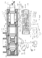
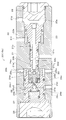
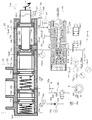
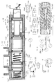
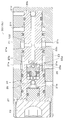
- FIG. 1 is a schematic diagram showing a first embodiment to which a brake device according to the present invention is applied. It is a schematic diagram which shows the brake device shown in FIG. It is sectional drawing which shows the regulator shown in FIG. 2, and is a figure which shows the state in which the pilot pressure is not provided. It is sectional drawing which shows the regulator shown in FIG. 2, and is a figure which shows the state in which the pilot pressure is provided. It is a schematic diagram showing a second embodiment of the brake device according to the present invention. It is a schematic diagram showing a third embodiment of the brake device according to the present invention. It is a schematic diagram showing a fourth embodiment of a brake device according to the present invention. It is a schematic diagram showing a fifth embodiment of a brake device according to the present invention. It is sectional drawing which shows the regulator shown in FIG. 8, and is a figure which shows the state in which the pilot pressure is not provided.
- FIG. 1 is a schematic diagram showing the configuration of the hybrid vehicle
- FIG. 2 is a schematic diagram showing the configuration of a brake device
- FIGS. 3 and 4 are cross-sectional views showing a regulator that is a mechanical pressure regulator. .
- the hybrid vehicle is a vehicle in which driving wheels, for example, left and right front wheels Wfl and Wfr are driven by a hybrid system.
- the hybrid system is a power train that uses a combination of two types of power sources, the engine 1 and the motor 2.
- the parallel hybrid system is a system in which wheels are directly driven by both the engine 1 and the motor 2.
- there is a serial hybrid system in which wheels are driven by the motor 2, and the engine 1 acts as a power supply source to the motor 2.
- a hybrid vehicle equipped with this parallel hybrid system includes an engine 1 and a motor 2.
- the driving force of the engine 1 is transmitted to the driving wheels (left and right front wheels Wfl, Wfr in the first embodiment) via the power split mechanism 3 and the power transmission mechanism 4. Is transmitted to the drive wheels via the power transmission mechanism 4.
- the power split mechanism 3 appropriately splits the driving force of the engine 1 into a vehicle driving force and a generator driving force.
- the power transmission mechanism 4 appropriately integrates the driving forces of the engine 1 and the motor 2 in accordance with traveling conditions and transmits them to the driving wheels.
- the power transmission mechanism 4 adjusts the driving force ratio transmitted between the engine 1 and the motor 2 between 0: 100 and 100: 0.
- the power transmission mechanism 4 has a speed change function.
- the motor 2 assists the output of the engine 1 to increase the driving force, while generating electric power and charging the battery 7 when the vehicle is braked.
- the generator 5 generates power based on the output of the engine 1 and has a starter function when starting the engine.
- the motor 2 and the generator 5 are electrically connected to the inverter 6, respectively.
- the inverter 6 is electrically connected to a battery 7 serving as a DC power source.
- the inverter 6 converts the AC voltage input from the motor 2 and the generator 5 into a DC voltage and supplies it to the battery 7, or vice versa.
- the DC voltage is converted into an AC voltage and output to the motor 2 and the generator 5.
- the regenerative brake device A is constituted by the motor 2, the inverter 6 and the battery 7, and the regenerative brake device A is detected by the pedal stroke sensor 11a (or the pressure sensor P). Regenerative braking force based on the brake operation state is generated on any of the wheels Wfl, Wfr, Wrl, Wrr (in the first embodiment, left and right front wheels Wfl, Wfr driven by the motor 2 as a driving source). It is.
- the engine 1 is controlled by an engine ECU (electronic control unit) 8.
- the engine ECU 8 outputs an opening degree command to an electronic control throttle according to an engine output request value from a hybrid ECU (electronic control unit) 9 described later. Adjust the rotation speed.
- the hybrid ECU 9 is connected so that the inverters 6 can communicate with each other.
- the hybrid ECU 9 derives necessary engine output, electric motor torque, and generator torque from the accelerator opening and the shift position (calculated from a shift position signal input from a shift position sensor not shown), and the derived engine output request value Is transmitted to the engine ECU 8 to control the driving force of the engine 1, and the motor 2 and the generator 5 are controlled through the inverter 6 in accordance with the derived electric motor torque request value and generator torque request value.
- the hybrid ECU 9 is connected to the battery 7 and monitors the charging state, the charging current, and the like of the battery 7. Further, the hybrid ECU 9 is also connected to an accelerator opening sensor (not shown) that is assembled to an accelerator pedal (not shown) and detects the accelerator opening of the vehicle, and inputs an accelerator opening signal from the accelerator opening sensor. ing.
- the brake ECU 17 is connected to the hybrid ECU 9 so as to be communicable with each other, and performs cooperative control of the regenerative brake and the hydraulic brake performed by the motor 2 so that the total braking force of the vehicle is equivalent to that of the vehicle having only the hydraulic brake. .
- the brake ECU 17 gives the hybrid ECU 9 a regeneration request value that is a share of the regenerative braking device out of the total braking force. Output as braking force.
- the hybrid ECU 9 derives an actual regeneration execution value that is actually acted as a regeneration brake in consideration of the vehicle speed, the battery charging state, and the like based on the input regeneration request value (target regeneration braking force), and the regeneration corresponding to the actual regeneration execution value.
- the motor 2 is controlled via the inverter 6 so as to generate a braking force, and the derived actual regeneration execution value is output to the brake ECU 17.
- the brake ECU 17 stores in advance in the memory the hydraulic braking force applied to the wheel W as a map, a table or an arithmetic expression when the brake hydraulic pressure is supplied to the wheel cylinder WC.
- the brake ECU 17 stores a target regenerative braking force applied to the wheel W according to a brake operation state that is a stroke (or master cylinder pressure) of the brake pedal in a memory in advance as a map, a table, or an arithmetic expression.
- the hybrid vehicle is provided with a brake device B that brakes the vehicle by directly applying a hydraulic braking force to each wheel Wfl, Wfr, Wrl, Wrr.
- the brake device B includes a brake pedal 11 that is a brake operation member, a stroke simulator unit 12, a master cylinder 13, a reservoir tank 14, a master piston drive hydraulic pressure adjustment device 15 (hereinafter referred to as drive hydraulic pressure adjustment device 15).
- a brake hydraulic pressure adjusting device 16 a brake ECU 17, and a wheel cylinder WC.
- the wheel cylinder WC regulates the rotation of the wheel W, and is provided in the caliper CL.
- brake fluid pressure brake fluid pressure
- each piston (not shown) of the wheel cylinder WC presses a pair of brake pads (not shown) that are friction members.
- the disc rotor DR which is a rotating member that rotates integrally with the wheel W, is sandwiched from both sides to restrict its rotation.
- the disc type brake is adopted, but a drum type brake may be adopted.
- the wheel W is one of the left and right front and rear wheels Wfl, Wfr, Wrl, and Wrr.
- a pedal stroke sensor 11a for detecting a brake pedal stroke which is a brake operation state when the brake pedal 11 is depressed.
- the pedal stroke sensor 11 a is connected to the brake ECU 17, and a detection signal is output to the brake ECU 17.
- the brake pedal 11 is connected to the stroke simulator unit 12 via a push rod 18.
- the stroke simulator unit 12 includes a body 12a, a hole 12b formed in the body 12a, a piston 12c capable of liquid-tight sliding in the hole 12b, and a hydraulic chamber 12d formed by the body 12a and the piston 12c. And a stroke simulator 12e communicated with the hydraulic chamber 12d.
- the body 12 a is integrally connected to the body 13 a of the master cylinder 13.
- a connecting portion 12c1 to which the push rod 18 is connected is formed on one end side in the sliding direction (axial direction) of the piston 12c.
- a rod 12f is integrally provided on the other end side opposite to the push rod 18 in the sliding direction of the piston 12c.
- the other end portion 12f1 of the rod 12f opposite to the piston 12c penetrates the partition wall 12a1 separating the hydraulic pressure chamber 12d of the stroke simulator portion 12 and the driving hydraulic pressure chamber 13e of the master cylinder 13 and is supported in a liquid-tight manner. Yes.
- the partition wall 12a1 forms part of the body 12a.
- the hydraulic chamber 12d communicates with the reservoir tank 14 via the first input / output port 12a2, and also communicates with the stroke simulator 12e via the oil passage 12g connected to the second input / output port 12a3.
- the stroke simulator 12e is generally well known, and causes the brake pedal 11 to generate a stroke having a magnitude corresponding to the operation state of the brake pedal 11.
- the stroke simulator 12e includes a piston 12e2 that slides fluidly in the housing 12e1, a hydraulic chamber 12e3 formed between the housing 12e1 and the piston 12e2, and a direction in which the piston 12e2 reduces the volume of the hydraulic chamber 12e3.
- a spring 12e4 for biasing is provided.
- the master cylinder 13 forms a hydraulic pressure (master cylinder pressure) according to the operating force of the brake pedal 11 that is a brake operating member by the driver, supplies the hydraulic pressure to the wheel cylinder WC, and a hydraulic braking force is applied to the wheel W by the hydraulic pressure. It is a device that can be generated.
- the master cylinder 13 is a tandem master cylinder and includes a body 13a.
- a cylinder hole 13b is formed in the body 13a.
- first and second pistons 13c and 13d are arranged side by side so as to be slidable in a liquid-tight manner.
- a driving hydraulic pressure chamber 13e for driving the first and second pistons 13c and 13d is formed between the first piston 13c and the partition wall 12a1.
- the other end portion 12f1 of the rod 12f faces the drive hydraulic pressure chamber 13e so as to be able to reciprocate.
- a step portion 12a2 is formed in the partition wall 12a1, and one end side of the first piston 13c comes into contact with the step portion 12a2. Even if the first piston 13c contacts the stepped portion 12a2, the drive hydraulic pressure chamber 13e can secure a volume.
- a first hydraulic pressure chamber 13f that forms a master cylinder pressure is formed between the first piston 13c and the second piston 13d, and a master cylinder pressure is formed between the second piston 13d and the bottom wall 13a1.
- a second hydraulic pressure chamber 13g is formed.
- a biasing member 13h for example, a spring
- an urging member 13i for example, a spring
- the second piston 13d When the hydraulic pressure is not supplied to the driving hydraulic pressure chamber 13e (for example, when the brake pedal 11 is not depressed), the second piston 13d is urged by the urging member 13h and is in a predetermined position.
- the piston 13c is biased by a biasing member 13i and is in a predetermined position (see FIG. 2).
- the predetermined position of the first piston 13c is a position where one end of the first piston 13c abuts on the stepped portion 12a2 and is positioned and fixed, and the other end of the first piston 13c is a position immediately before closing the port 13k. ing.
- the predetermined position of the second piston 13d is a position where the other end of the second piston 13d is positioned and fixed immediately before the port 13l is closed.
- the body 13a of the master cylinder 13 has a port 13j for communicating the drive hydraulic pressure chamber 13e and the regulator 15c, a port 13k for communicating the first hydraulic pressure chamber 13f and the reservoir tank 14, and a second fluid.
- the driving hydraulic pressure adjusting device 15 adjusts the pressure in the driving hydraulic pressure chamber 13e of the master cylinder 13 by the hydraulic pressures of both the high pressure source and the low pressure source.
- the pressure part 15b and the regulator 15c are provided.
- the drive hydraulic pressure adjusting device 15 forms a regulator pressure corresponding to the amount of operation of the brake pedal 11 by at least one of the electric pressure adjusting unit 15b and the regulator 15c receiving the pressure from the pressure supply device 15a. This is supplied to the drive hydraulic pressure chamber 13e of the cylinder 13.
- the pressure supply device 15a includes a reservoir tank 14 that is a low pressure source, an accumulator 15a1 that is a high pressure source, a pump 15a2 that sucks brake fluid from the reservoir tank 14 and pumps it to the accumulator 15a1, and an electric motor that drives the pump 15a2. 15a3.
- the reservoir tank 14 (low pressure source) is connected to the drive hydraulic pressure chamber 13e of the master cylinder 13.
- the low pressure source is at a lower pressure than the high pressure source.
- the accumulator 15a1 is also connected to the drive hydraulic pressure chamber 13e of the master cylinder 13.
- the pressure supply device 15a includes a pressure sensor 15a4 that detects the pressure of the brake fluid supplied from the accumulator 15a1 and outputs the pressure from the brake ECU 17.
- the electric pressure adjustment unit 15b includes a normally-open pressure reduction control valve 15b1 that controls the flow of brake fluid between the reservoir tank 14 and the drive hydraulic pressure chamber 13e, and an accumulator 15a1 and the drive hydraulic pressure chamber 13e. And a normally closed pressure increase control valve 15b2 for controlling the flow of the brake fluid, and a pressure sensor 15b3 for detecting the fluid pressure in the drive fluid pressure chamber 13e.
- the pressure reduction control valve 15b1 and the pressure increase control valve 15b2 are electromagnetic valves that operate in response to a command from the brake ECU 17.
- the pressure sensor 15b3 outputs a detection signal to the brake ECU 17.
- the electric pressure adjustment unit 15b adjusts the hydraulic pressure supplied from the accumulator 15a1 to the driving hydraulic pressure chamber 13e by the pressure increase control valve 15b1 while monitoring the detection value by the pressure sensor 15b3, and supplies the pressure to the reservoir tank 14.
- the brake fluid discharge (the hydraulic pressure discharged from the drive hydraulic pressure chamber 13e to the reservoir tank 14) is adjusted by the pressure reduction control valve 15b2, so that the stroke amount of the brake pedal 11 detected by the pedal stroke sensor 11a and the vehicle state
- the hydraulic pressure corresponding to the pressure can be supplied to the drive hydraulic pressure chamber 13e.
- the regulator 15c includes a regulator 20 as shown in FIG.
- a cylinder hole 21a is formed in the housing 21 of the regulator 20, and a high pressure port 21b, a low pressure port 21c, a pilot pressure input port 21d, an output port 21e, and a drain port 21f are formed.
- the high pressure port 21 b is directly connected to the accumulator 15 a 1 via the hydraulic oil passage 31.
- the low pressure port 21 c is connected to the reservoir tank 14 via a hydraulic oil passage 32.
- the pilot pressure input port 21d is connected to the hydraulic pressure chamber 12d of the stroke simulator section 12 via a hydraulic pressure oil path 33 connected to the oil path 12g.
- the output port 21e is connected to the driving hydraulic pressure chamber 13e of the master cylinder 13 through the hydraulic pressure oil passage 34.
- the drain port 21 f is connected to the reservoir tank 14.
- the hydraulic oil passage 31 is connected to the output port 21e via a hydraulic oil passage 35 that is branched in the middle.
- the first path L1 that connects the accumulator 15a1 that is the high pressure source and the high pressure port 21b is the first path L1 that connects the reservoir tank 14 that is the low pressure source and the low pressure port 21c by the hydraulic oil path 31.
- the second path L2 is connected to the stroke simulator section 12 which is a mechanical pilot pressure generating section and the pilot pressure input port 21d by the hydraulic oil path 32, and the third path L3 is connected to the driving fluid by the hydraulic oil path 33.
- the fourth path L4 connecting the pressure chamber 13e and the output port 21e is constituted by a hydraulic oil path 34.
- the fifth path L5 includes a hydraulic oil path 31 (a portion between the accumulator 15a1 and the connection point of the hydraulic oil path 35), a hydraulic oil path 35, an output port 21e, a pressure regulating chamber 20b, and an output port 21e.
- the hydraulic oil passage 34 and the port 13j are connected to the accumulator 15a1 and the driving hydraulic pressure chamber 13e via the output port 21e without bypassing (bypassing) the high pressure port 21b.
- a pressure increase control valve 15b2 is disposed on the hydraulic oil passage 35.
- a pressure reduction control valve 15 b 1 is disposed on the hydraulic oil passage 32.
- the pressure regulating piston 22 is slidably disposed in the cylinder hole 21a in a fluid-tight manner.
- the pressure adjusting piston 22 is configured such that a large-diameter portion 22a and a small-diameter portion 22b having a smaller diameter than the large-diameter portion 22a are integrally formed.
- Each area of the end surface on the large diameter portion 22a side and the end surface on the small diameter portion 22b side of the pressure regulating piston 22 is determined by the pilot pressure input port 21d due to the hydraulic pressure applied to both the high pressure port 21b and the low pressure port 21c by the regulator 20c.
- the hydraulic pressure is set so as to be output from the output port 21e according to the pressure applied to the output port 21e.
- a pilot hydraulic pressure chamber 20a is formed between the large diameter portion 22a side end (right end in the figure) of the pressure regulating piston 22 and a nut 29 that closes the right opening end of the cylinder hole 21a, and a small diameter portion 22b of the pressure regulating piston 22 is formed.
- a pressure regulating chamber 20b is formed at the side end (the left end side in the figure).
- the pilot fluid pressure chamber 20a communicates with the pilot pressure input port 21d, and the pressure regulation chamber 20b communicates with the output port 21e (two in this embodiment).
- the pressure regulating piston 22 is formed with a communication passage 22c communicating with the low pressure port 21c.
- a spring 23 is disposed in the pressure regulating chamber 20b, and urges the pressure regulating piston 22 in a direction to increase the volume of the pressure regulating chamber 20b.
- the pressure adjustment piston 22 When the hydraulic pressure is not applied to the pilot hydraulic pressure chamber 20a (for example, when the brake pedal 11 is not operated), the pressure adjustment piston 22 is urged in the right direction in the figure by the urging force of the spring 23, and the right end of the pressure adjustment piston 22 Is abutted against the nut 29 and fixed in position. At this time, since a pressure reducing valve described later is in an open state, the output port 21e communicates with the low pressure port 21c via the pressure regulating chamber 20b and the communication passage 22c.
- a cylinder member 24 having an isolation portion 24c that divides the two holes 24a and 24b is fixed to the left end of the cylinder hole 21a in the figure.
- the hole 24a faces the pressure regulating chamber 20b, and the valve body 25 is slidably disposed in the hole 24a.
- a ball 25a is fixed to the end of the valve body 25 on the pressure regulating chamber 20b side, and the ball 25a is attachable to and detachable from a valve seat 22d formed at the end of the pressure regulating piston 22 on the pressure regulating chamber 20b side. .
- the ball 25a is seated on the valve seat 22d when the pressure regulating piston 22 slides a predetermined distance in the direction of decreasing the volume of the pressure regulating chamber 20b.
- These balls 25a and the valve seat 22d constitute a pressure reducing valve, and communicate or block between the pressure regulating chamber 20b and the communication passage 22c to reduce the hydraulic pressure (regulator hydraulic pressure) in the pressure regulating chamber 20b.
- the valve body 25 is urged toward the valve seat 22d by a spring 25b.
- a small-diameter protrusion 25c is integrally provided at the opposite end of the valve body 25 to the pressure regulating chamber 20b.
- the valve body 25 is formed with a communication passage 25d that communicates the space formed by the hole 24a, the isolation part 24c, and the valve body 25 with the pressure regulating chamber 20b.
- a ball-shaped valve body 26 is movably disposed in the hole 24b of the cylinder member 24, and is detachable from a valve seat 24c2 of the valve hole 24c1 formed in the isolation part 24c.
- the valve hole 24c1 allows the protrusion 25c of the valve body 25 to advance and retract, and the inner diameter of the valve hole 24c1 is set larger than the outer diameter of the protrusion 25c.
- the valve body 26 is urged toward the valve seat 24c2 by the spring 26a, and is normally pressed and seated on the valve seat 24c2. When the valve body 25 slides in the left direction in the figure, the valve body 26 is pushed by the projection 25c of the valve body 25 and is detached from the valve seat 24c2.
- the cylinder member 24 is formed with a communication path 24d that communicates the hole 24b with the high-pressure port 21b.
- the valve body 26, the valve seat 24c2, and the spring 26a constitute a pressure increasing valve, and cooperate with the pressure reducing valve described above to communicate or block between the pressure regulating chamber 20b and the communication passage 24d. Increase the fluid pressure (regulator fluid pressure).
- the hole 24b is closed by a plug 27, and the cylinder member 24 is fixed by a nut 28.
- the regulator 20 responds to the hydraulic pressure supplied to the pilot hydraulic pressure chamber 20a by the pressure applied to both the high pressure port 21b and the low pressure port 21c.
- the hydraulic pressure can be output from the output port 21e.
- the reservoir tank 14 which is a low pressure source and the drive hydraulic pressure chamber 13e of the master cylinder 13 are the hydraulic pressure oil passage 32, the low pressure port 21c, the communication passage 22c, the pressure adjustment chamber 20b, the output port 21e, It is connected (communication) by an oil passage (the “path connecting the low pressure source and the drive hydraulic pressure chamber” described in the claims) composed of the pressure oil passage 34 and the port 13j.
- a decompression control valve 15b1 is provided in this path.
- the accumulator 15a1 which is a high pressure source and the drive hydraulic pressure chamber 13e of the master cylinder 13 are a hydraulic oil passage 31 (a portion between the connection point of the accumulator 15a1 and the hydraulic oil passage 35), a hydraulic oil passage. 35, an oil passage (a “path connecting the high pressure source and the drive hydraulic pressure chamber” described in the claims) including a pressure regulating chamber 20b, an output port 21e, a hydraulic oil passage 34, and a port 13j. (Communication).
- a pressure increase control valve 15b2 is provided in this path.
- the accumulator 15a1 and the drive hydraulic pressure chamber 13e are connected to the hydraulic oil passage 31, the high pressure port 21b, the communication passage 24d, the valve hole 24c1, the communication passage 25d,
- the pressure regulating chamber 20b, the output port 21e, the hydraulic oil passage 34, and the oil passage composed of the port 13j are connected.
- the oil passage can intermittently communicate the accumulator 15a1 and the drive hydraulic pressure chamber 13e while the regulator 15c is operating.
- This oil path is a path that connects the accumulator 15a1 and the drive hydraulic pressure chamber 13e via the high-pressure port 21b and the output port 21e.
- the brake fluid pressure adjusting device 16 includes a holding valve 16a, a pressure reducing valve 16b, a reservoir tank 16c, a pump 16d, and an electric motor 16e.
- the holding valve 16a is a normally-open electromagnetic on-off valve that is disposed between the port 13m of the master cylinder 13 and the wheel cylinder WC and communicates and blocks between the master cylinder 13 and the wheel cylinder WC.
- the holding valve 16a is configured as a two-position valve that can be controlled to be in a communication state (state shown in the figure) when de-energized in accordance with a command from the brake ECU 17 and to be cut off when energized.
- the holding valve 16a is provided with a check valve 16f in parallel that allows the flow from the wheel cylinder WC to the master cylinder 13 and restricts the flow in the reverse direction.
- the pressure reducing valve 16b is a normally closed electromagnetic on-off valve that communicates and blocks between the wheel cylinder WC and the reservoir tank 16c.
- the pressure reducing valve 16b is configured as a two-position valve that can be controlled to be in a shut-off state (state shown in the figure) when de-energized in accordance with a command from the brake ECU 17 and in a communication state when energized.
- the reservoir tank 16c stores brake fluid and communicates with the port 13m of the master cylinder 13.
- a pump 16d is disposed between the reservoir tank 16c and the master cylinder 13.
- the pump 16d has a suction port communicating with the reservoir tank 16c and a discharge port communicating between the master cylinder 13 and the holding valve 16a via a check valve 16g.
- the check valve 16g is a check valve that allows flow from the pump 16d to the master cylinder 13 and restricts flow in the reverse direction.
- the pump 16d is driven by the operation of the electric motor 16e according to the command of the brake ECU 17.
- the pump 16d sucks the brake fluid in the wheel cylinder WC or the brake fluid stored in the reservoir tank 16c and returns it to the master cylinder 13 in the pressure reduction mode of the ABS control.
- a damper 16h is disposed upstream of the pump 16d in order to relieve pulsation of the brake fluid discharged from the pump 16d.
- the brake fluid pressure adjusting device 16 is provided in the vicinity of the wheel W and includes a wheel speed sensor 16i that detects the wheel speed of the wheel W. A detection signal indicating the wheel speed detected by the wheel speed sensor 16 i is output to the brake ECU 17.
- the brake ECU 17 switches and controls the opening and closing of the electromagnetic valves 16a and 16b based on the master cylinder pressure, the wheel speed state, and the longitudinal acceleration, and requires the electric motor 16e.
- ABS control anti-lock brake control
- ABS control for adjusting the brake hydraulic pressure applied to the wheel cylinder WC, that is, the braking force applied to the wheel W, is executed.
- the first to fourth paths L1 to L4 are opened when the pressure increase control valve 15b2 and the pressure reduction control valve 15b1 are de-energized due to a failure of the electric system.
- the path connecting the reservoir tank 14 (low pressure source) and the drive hydraulic pressure chamber 13e includes the second path L2 and the fourth path L4.
- the pressure reducing control valve 15b1 is a normally open control valve. Therefore, when the non-energized state is established, the path connecting the low pressure source 14 and the drive hydraulic pressure chamber 13e is not blocked by the pressure reducing control valve 15b1.
- the regulator 15c mechanical pressure adjusting unit
- the high pressure port 21b, the low pressure port 21c, the pilot pressure input port 21d and the output port 21e are respectively connected to the accumulator 15a1 (high pressure source) and the reservoir tank 14 (low pressure source).
- the stroke simulator unit 12 (mechanical pilot pressure generating unit) and the driving hydraulic pressure chamber 13e are connected to each other, and the hydraulic pressure corresponding to the operation amount of the brake pedal 11 (brake operating member) is output from the output port 21e.
- the hydraulic pressure in the drive hydraulic pressure chamber 13e becomes a hydraulic pressure corresponding to the operation amount of the brake pedal 11, and the master pistons 13c and 13d are driven by the hydraulic pressure corresponding to the operation amount of the brake pedal 11.
- the fifth path L5 is a path that bypasses the high-pressure port 21b of the regulator 15c and connects the accumulator 15a1 and the driving hydraulic pressure chamber 13e, but the pressure increase control valve 15b2 is a normally closed control valve. In the non-energized state, the flow of brake fluid from the accumulator 15a1 to the drive hydraulic pressure chamber 13e is blocked by the pressure increase control valve 15b2.
- the regulator 15c operates in the same manner as the above-described non-energized state of the control valve. In addition to this, it is also possible to perform pressure regulation by operating the pressure increase control valve 15b2 and the pressure reduction control valve 15b1.
- the piston 12c interlocked with the brake pedal 11 (brake operation member) and the body 12a (cylinder) on which the piston 12c slides are configured.
- the piston 12c and the body 12a The formed hydraulic pressure chamber 12d is a mechanical pilot pressure generator.
- the mechanical pilot pressure generating unit generates a pilot hydraulic pressure corresponding to the operation amount of the brake pedal 11.
- the mechanical pilot pressure generator generates the hydraulic pressure in the hydraulic chamber 12d to which the stroke simulator 12e is connected as the pilot hydraulic pressure. Thereby, the pilot hydraulic pressure according to the operation amount of the brake pedal 11 can be appropriately generated with a simple configuration.
- the pressure reducing control valve 15b1 is provided in the second path L2.
- the pressure reducing control valve 15b1 is not provided in the fourth path L4 where the flow rate of the brake fluid is larger than that in the second path L2, but is provided in the second path L2 where the flow rate of the brake fluid is smaller than that in the fourth path L4.
- the flow rate of the brake fluid between the chamber 13e and the regulator 15c (pressure adjusting unit) is not limited to the maximum flow rate of the pressure reduction control valve 15b1.
- FIG. 5 is a schematic diagram showing the configuration of the brake device B.
- the second embodiment differs from the first embodiment in that a pilot pressure control valve 41 is provided.
- symbol is attached
- the pilot pressure control valve 41 is disposed on the hydraulic oil passage 33, and brake fluid between the stroke simulator unit 12 (mechanical pilot pressure generating unit) and the pilot pressure input port 21d. It is a normally open type electromagnetic control valve that controls the flow of air.
- the pilot pressure control valve 41 is controlled to open and close based on a command from the brake ECU 17.
- the brake ECU 17 closes the pilot pressure control valve 41 when there is a regeneration request. Therefore, since the pilot pressure control valve 41 is closed, the output fluid corresponding to the operation amount of the brake pedal 11 of the stroke simulator unit 12 (mechanical pilot pressure generating unit) is applied to the pilot pressure input port 21d of the regulator 15c. No pressure is applied, and pressure regulation by the regulator 15c is not performed. Therefore, the hydraulic pressure corresponding to the regeneration request can be applied to the drive hydraulic pressure chamber 13e by the control of the pressure increase control valve 15b2 and the pressure reduction control valve 15b1, and desired regenerative braking can be performed.
- the brake ECU 17 sets the regeneration request according to the operation amount detected based on the pedal stroke sensor 11a. To do. Therefore, the vehicle state detection means for detecting that there is a regeneration request is the brake ECU 17.
- the brake ECU 17 (control means) opens the pilot pressure control valve 41 when the anti-lock brake control is being performed. Therefore, since the pilot pressure control valve 41 is opened, both the hydraulic pressure adjusted by the regulator 15c and the hydraulic pressure adjusted by the control of the pressure increase control valve 15b2 and the pressure reduction control valve 15b1 are obtained. Is granted. Therefore, even if a large amount of brake fluid is required for the anti-lock brake control, it can sufficiently cope with it.
- the brake ECU 17 switches the opening and closing of the electromagnetic valves 16a and 16b based on the master cylinder pressure, the wheel speed state, and the longitudinal acceleration, and operates the electric motor 16e as necessary to operate the wheel cylinder.
- ABS control anti-lock brake control
- ABS control for adjusting the brake fluid pressure applied to the WC, that is, the braking force applied to the wheel W, is executed. Therefore, the vehicle state detection means for detecting that the antilock brake control is being performed is the brake ECU 17.
- the brake ECU 17 serving as the control means causes the brake fluid between the stroke simulator unit 12 (mechanical pilot pressure generating unit) and the pilot pressure input port 21d to flow. Since the pilot pressure control valve 41 that controls the flow can be controlled according to the vehicle state detected by the brake ECU 17 that is the vehicle state detection means, the pressure adjustment by the regulator 15c is appropriately performed according to the vehicle state. Can do.
- FIG. 6 is a schematic diagram showing the configuration of the brake device B.
- the pressure reduction control valve 15b1 is provided in the fourth path L4 between the output port 21e and the drive hydraulic pressure chamber 13e, and the check valve 42 is provided in parallel to the pressure reduction control valve 15b1.
- the fifth path L5 connecting the high pressure source and the drive hydraulic pressure chamber is not provided with a regulator.
- the hydraulic oil passage 35 is connected to the hydraulic oil passage 34.
- the check valve 42 allows the flow from the regulator 15c to the drive hydraulic pressure chamber 13e, but restricts the flow in the opposite direction. Since the flow passage area of the check valve 42 is larger than the flow passage area of the pressure reduction control valve 15b1, the flow rate of the brake fluid when increasing pressure can be earned. Note that the operational effects of the third embodiment are the same as the operational effects of the second embodiment described above.
- FIG. 7 is a schematic diagram showing the configuration of the brake device B.
- the fourth embodiment is different from the second embodiment in that the fifth path L5 connects the accumulator 15a1 and the driving hydraulic pressure chamber 13e via the low pressure port 21c and the output port 21e of the regulator 20. .
- the hydraulic oil passage 35 is connected to the hydraulic oil passage 32.
- the fifth path L5 includes the hydraulic oil path 31 (a portion between the accumulator 15a1 and the connection point of the hydraulic oil path 35), the hydraulic oil path 35, and the hydraulic oil path 32 (the hydraulic oil path 35).
- FIG. 8 is a schematic diagram showing the configuration of the brake device B.
- the fifth embodiment is different from the first embodiment in that the first hydraulic chamber 13f of the master cylinder 13 is adopted as a mechanical pilot pressure generating unit.
- the mechanical pilot pressure generator includes a first piston 13c that is a master piston and a master cylinder 13 on which the master piston 13c slides.
- the hydraulic pressure in the first hydraulic pressure chamber 13f, which is a master chamber formed by the master piston 13c and the master cylinder 13, is generated as a pilot hydraulic pressure.
- the second hydraulic pressure chamber 13g of the master cylinder 13 may be employed as the mechanical pilot pressure generator.
- the regulator 15c preferably employs the regulator 30 shown in FIG.
- the regulator 30 is set so that the area of the end face (right end face in the figure) desired for the pilot hydraulic pressure chamber 20a in the pressure adjustment piston 122 is smaller than the area of the end face (left end face in the figure) desired for the pressure adjustment chamber 20b.
- the other configurations are basically the same, and the same reference numerals are given and description thereof is omitted.
- the hydraulic pressure in the pilot hydraulic chamber 20a and the hydraulic pressure in the first hydraulic chamber 13f are the same, and the hydraulic pressure in the pressure regulating chamber 20b and the hydraulic pressure in the drive hydraulic chamber 13e are the same.
- the regulator 30 is configured such that the hydraulic pressure in the driving hydraulic pressure chamber 13e exerts on the first piston 13c in the left direction in the drawing, and the hydraulic pressure in the first hydraulic pressure chamber 13f in the right direction in the drawing with respect to the first piston 13c It is comprised so that it may become smaller than the force which acts. In this case, the pressure receiving areas of both end faces of the first piston 13c are substantially equal.
- the regulator 30 causes the force exerted by the hydraulic pressure in the driving hydraulic pressure chamber 13e to the left in the drawing with respect to the first piston 13c to be in the first hydraulic pressure chamber 13f. It is preferable that the hydraulic pressure is less than the force exerted on the first piston 13c in the right direction in the figure.
- the operation according to the fifth embodiment will be described.
- the pressure increase control valve 15b2 and the pressure reduction control valve 15b1 are de-energized due to the failure of the electrical system, the first to fourth paths L1 to L4 are opened.
- the path connecting the reservoir tank 14 (low pressure source) and the drive hydraulic pressure chamber 13e includes the second path L2 and the fourth path L4, but the pressure reducing control valve 15b1 is a normally open control valve. Therefore, when the non-energized state is established, the path connecting the low pressure source 14 and the drive hydraulic pressure chamber 13e is not blocked by the pressure reducing control valve 15b1.
- the high pressure port 21b, the low pressure port 21c, the pilot pressure input port 21d, and the output port 21e are respectively an accumulator 15a1 (high pressure source) and a reservoir tank 14 (low pressure source).
- the master cylinder is connected to the first hydraulic pressure chamber 13f (mechanical pilot pressure generator) and the driving hydraulic pressure chamber 13e.
- the first piston 13c is directly pressed by the rod 12f, so that the master is operated in the first hydraulic chamber 13f.
- a cylinder pressure is formed.
- the hydraulic pressure in the drive hydraulic pressure chamber 13e becomes the hydraulic pressure corresponding to the operation amount of the brake pedal 11, and the master pistons 13c and 13d are driven by the hydraulic pressure corresponding to the operation amount of the brake pedal 11.
- the hydraulic pressure in the drive hydraulic pressure chamber 13e cannot be adjusted by the control of the pressure increase control valve 15b2 and the pressure reduction control valve 15b1, and the brake fluid is accumulated by the electric pump 15a2.
- the brake pedal 11 can generate a braking force corresponding to the operation amount.
- the pressure increase control valve 15b2, and the pressure reduction control valve 15b1 operate normally without any failure in the electrical system
- the pressure increase is started before the supply of the regulator pressure is started by the regulator 15c.
- the master cylinder pressure (pilot hydraulic pressure) corresponding to the operation amount of the brake pedal 11 is input to the pilot pressure input port 21d by the operation of the control valve 15b2 and the pressure reduction control valve 15b1.
- the regulator 15c operates as described above, the pressure regulation by the regulator 15c and the pressure regulation by the operation of the pressure increase control valve 15b2 and the pressure reduction control valve 15b1 can be performed together.
- the present invention is not limited to a brake device mounted on a hybrid vehicle, but can also be applied to a vehicle brake device mounted only with an engine.
- the present invention can be applied not only to a brake device that can only perform ABS control but also to a brake device that can also perform ESC control.
- the brake device capable of ESC control is such that a differential pressure control valve is provided between the master cylinder 13 and the brake fluid pressure adjusting device 16 in the first embodiment described above.
- the brake device can generate a braking force corresponding to the operation amount of the brake operation member as long as the hydraulic pressure remains in the high pressure source even when the electrical system fails. Suitable for use in brake systems.
- Electric motor 15b Electric pressure regulator, 15b1 ... Pressure reduction control valve, 15b2 ... Pressure increase control valve, 15c, 20 ... Regulator ( 21b ... high pressure port, 21c ... low pressure port, 21d ... pilot pressure input port, 21e ... output port, 16 ... brake hydraulic pressure adjusting device, 17 ... brake ECU (control means, vehicle state detection means) ), 41 ... pilot pressure control valve, A ... regenerative brake device, B ... brake device.
Landscapes
- Engineering & Computer Science (AREA)
- Transportation (AREA)
- Mechanical Engineering (AREA)
- Physics & Mathematics (AREA)
- Fluid Mechanics (AREA)
- Regulating Braking Force (AREA)
- Valves And Accessory Devices For Braking Systems (AREA)
- Braking Systems And Boosters (AREA)
Abstract
Description
以下、本発明に係るブレーキ装置をハイブリッド車に適用した第1の実施形態を図面を参照して説明する。図1はそのハイブリッド車の構成を示す概要図であり、図2はブレーキ装置の構成を示す概要図であり、図3および図4は機械式の調圧部であるレギュレータを示す断面図である。
次に、本発明に係るブレーキ装置の第2の実施の形態を図5を参照して説明する。図5はブレーキ装置Bの構成を示す概要図である。
次に、本発明に係るブレーキ装置の第3の実施の形態を図6を参照して説明する。図6はブレーキ装置Bの構成を示す概要図である。
次に、本発明に係るブレーキ装置の第4の実施の形態を図7を参照して説明する。図7はブレーキ装置Bの構成を示す概要図である。
次に、本発明に係るブレーキ装置の第5の実施の形態を図8を参照して説明する。図8はブレーキ装置Bの構成を示す概要図である。
Claims (7)
- マスタピストン(13c,13d)を駆動する駆動液圧室(13e)と、
電動ポンプ(15a2)により圧送されたブレーキ液の液圧を蓄圧する高圧力源(15a1)と、
前記高圧力源よりも低圧の低圧力源(14)と、
前記高圧力源と前記駆動液圧室とを接続する経路に設けられ、前記高圧力源から前記駆動液圧室へのブレーキ液の流れを制御する増圧制御弁(15b2)と、
前記低圧力源と前記駆動液圧室とを接続する経路に設けられ、前記駆動液圧室から前記低圧力源へのブレーキ液の流れを制御する減圧制御弁(15b1)と、を備え、
前記増圧制御弁と前記減圧制御弁の制御により前記駆動液圧室の液圧を調整するブレーキ装置(B)において、
ブレーキ操作部材(11)の操作量に応じたパイロット液圧を発生させる機械式のパイロット圧発生部(12,13)と、
前記高圧力源に接続される高圧ポート(21b)と、前記低圧力源に接続される低圧ポート(21c)と、前記機械式のパイロット圧発生部に接続されるパイロット圧入力ポート(21d)と、前記駆動液圧室に接続される出力ポート(21e)とを有し、前記高圧ポートおよび前記低圧ポートの両ポートに加えられている液圧により前記パイロット圧入力ポートに加えられている圧力に応じた液圧を前記出力ポートから出力する機械式の調圧部(15c,20,30)と、
前記高圧力源と前記高圧ポートとを接続する第1経路(L1)と、
前記低圧力源と前記低圧ポートとを接続する第2経路(L2)と、
前記機械式のパイロット圧発生部と前記パイロット圧入力ポートとを接続する第3経路(L3)と、
前記駆動液圧室と前記出力ポートとを接続する第4経路(L4)と、
前記高圧力源と前記駆動液圧室とを接続する経路として設けられ、前記調圧部の前記高圧ポートをバイパスして前記高圧力源と前記駆動液圧室とを接続する第5経路(L5)と、を備え、
前記低圧力源と前記駆動液圧室とを接続する経路は、前記第2経路および前記第4経路を含んで構成され、
前記減圧制御弁は、前記第2経路又は前記第4経路に設けられた常開型の制御弁であり、
前記増圧制御弁は、前記第5経路に設けられた常閉型の制御弁であり、
前記第1経路から前記第4経路は、前記増圧制御弁および前記減圧制御弁が非通電状態となった場合に開放されるように構成されていることを特徴とするブレーキ装置。 - 請求項1において、前記第3経路に設けられ、前記機械式のパイロット圧発生部と前記パイロット圧入力ポートとの間のブレーキ液の流れを制御する常開型のパイロット圧制御弁(41)と、
所定の車両状態を検出する車両状態検出手段(17)と、
前記車両状態検出手段による車両状態の検出結果に応じて、前記パイロット圧制御弁を制御する制御手段(17)と、
を備えていることを特徴とするブレーキ装置。 - 請求項2において、前記車両状態検出手段は、回生要求があることを検出し、
前記制御手段は、前記車両状態検出手段により前記回生要求があることが検出されている場合に、前記パイロット圧制御弁を閉弁させることを特徴とするブレーキ装置。 - 請求項2または請求項3において、前記車両状態検出手段は、アンチロックブレーキ制御中であることを検出し、
前記制御手段は、前記車両状態検出手段により前記アンチロックブレーキ制御中であることが検出されている場合に、前記パイロット圧制御弁を開弁させることを特徴とするブレーキ装置。 - 請求項1乃至請求項4の何れか一項において、前記減圧制御弁は、前記第2経路に設けられていることを特徴とするブレーキ装置。
- 請求項1乃至請求項5の何れか一項において、前記機械式のパイロット圧発生部は、前記ブレーキ操作部材に連動するピストン(12c)と同ピストンが摺動するシリンダ(12a)とを有して構成され、前記ピストンと前記シリンダとにより形成されている液圧室(12d)であって、ストロークシミュレータ(12e)が接続される液圧室の液圧を、前記パイロット液圧として発生させることを特徴とするブレーキ装置。
- 請求項1乃至請求項5の何れか一項において、前記機械式のパイロット圧発生部は、前記マスタピストンと同マスタピストンが摺動するマスタシリンダ(13)とを有して構成され、前記マスタピストンと前記マスタシリンダとにより形成されているマスタ室の液圧を、前記パイロット液圧として発生させることを特徴とするブレーキ装置。
Priority Applications (3)
| Application Number | Priority Date | Filing Date | Title |
|---|---|---|---|
| US13/696,818 US9004617B2 (en) | 2010-05-20 | 2011-05-19 | Brake device |
| CN201180023876.2A CN102892651B (zh) | 2010-05-20 | 2011-05-19 | 制动装置 |
| DE112011101715.4T DE112011101715B4 (de) | 2010-05-20 | 2011-05-19 | Bremsvorrichtung |
Applications Claiming Priority (2)
| Application Number | Priority Date | Filing Date | Title |
|---|---|---|---|
| JP2010-116274 | 2010-05-20 | ||
| JP2010116274A JP5240237B2 (ja) | 2010-05-20 | 2010-05-20 | ブレーキ装置 |
Publications (1)
| Publication Number | Publication Date |
|---|---|
| WO2011145673A1 true WO2011145673A1 (ja) | 2011-11-24 |
Family
ID=44991765
Family Applications (1)
| Application Number | Title | Priority Date | Filing Date |
|---|---|---|---|
| PCT/JP2011/061484 Ceased WO2011145673A1 (ja) | 2010-05-20 | 2011-05-19 | ブレーキ装置 |
Country Status (5)
| Country | Link |
|---|---|
| US (1) | US9004617B2 (ja) |
| JP (1) | JP5240237B2 (ja) |
| CN (1) | CN102892651B (ja) |
| DE (1) | DE112011101715B4 (ja) |
| WO (1) | WO2011145673A1 (ja) |
Cited By (2)
| Publication number | Priority date | Publication date | Assignee | Title |
|---|---|---|---|---|
| CN104203681A (zh) * | 2012-03-21 | 2014-12-10 | 株式会社爱德克斯 | 车辆用的制动装置 |
| US12157444B2 (en) | 2020-05-13 | 2024-12-03 | Huawei Technologies Co., Ltd. | Hydraulic adjustment apparatus, hydraulic adjustment system, brake system, and control method |
Families Citing this family (23)
| Publication number | Priority date | Publication date | Assignee | Title |
|---|---|---|---|---|
| JP5838875B2 (ja) * | 2012-03-16 | 2016-01-06 | トヨタ自動車株式会社 | 液圧制御装置および液圧ブレーキシステム |
| JP5842712B2 (ja) * | 2012-03-30 | 2016-01-13 | 株式会社アドヴィックス | 車両用制動装置 |
| DE112012006423B4 (de) * | 2012-05-25 | 2018-07-19 | Toyota Jidosha Kabushiki Kaisha | Druckregler und mit dem Druckregler ausgerüstetes Hydraulikbremssystem |
| JP5705166B2 (ja) * | 2012-05-31 | 2015-04-22 | 株式会社アドヴィックス | 車両の制動装置 |
| JP5796554B2 (ja) * | 2012-07-12 | 2015-10-21 | 株式会社アドヴィックス | 車両用制動装置 |
| JP2014083959A (ja) * | 2012-10-23 | 2014-05-12 | Advics Co Ltd | ブレーキ装置 |
| JP5846111B2 (ja) * | 2012-11-22 | 2016-01-20 | 株式会社アドヴィックス | 車両用液圧ブレーキ装置 |
| DE102013201630A1 (de) * | 2013-01-31 | 2014-07-31 | Siemens Aktiengesellschaft | Bremseinheit für ein Fahrzeug und Fahrzeug mit einer derartigen Bremseinheit |
| JP6115944B2 (ja) * | 2013-05-27 | 2017-04-19 | 日立オートモティブシステムズ株式会社 | ブレーキ装置及びブレーキシステム |
| JP6331418B2 (ja) | 2013-06-28 | 2018-05-30 | 株式会社アドヴィックス | 車両用制動装置 |
| JP6278236B2 (ja) | 2014-01-29 | 2018-02-14 | 株式会社アドヴィックス | 車両用制動装置 |
| JP6149847B2 (ja) * | 2014-11-25 | 2017-06-21 | 株式会社アドヴィックス | 車両の制動装置 |
| JP6521309B2 (ja) * | 2015-09-01 | 2019-05-29 | 日立オートモティブシステムズ株式会社 | ブレーキ装置およびブレーキシステム |
| CN105235667A (zh) * | 2015-10-21 | 2016-01-13 | 奇瑞汽车股份有限公司 | 一种液压助力制动并实现协调再生制动的制动装置 |
| JP2018131479A (ja) * | 2017-02-13 | 2018-08-23 | 日立化成株式会社 | 摩擦材組成物、該摩擦材組成物を用いた摩擦材および摩擦部材 |
| JP6560298B2 (ja) * | 2017-05-25 | 2019-08-14 | トヨタ自動車株式会社 | 制動操作装置 |
| CN109094546B (zh) * | 2018-09-17 | 2022-07-12 | 奇瑞汽车股份有限公司 | 汽车制动系统及其控制方法 |
| KR102947661B1 (ko) * | 2020-02-04 | 2026-04-02 | 에이치엘만도 주식회사 | 전자식 브레이크 시스템 및 그 제어방법 |
| CN113665542B (zh) * | 2021-08-31 | 2022-10-18 | 中汽创智科技有限公司 | 一种集成线控制动系统、控制方法、存储介质和终端 |
| CN115571103B (zh) * | 2022-10-10 | 2026-04-21 | 安徽合力股份有限公司 | 一种无人驾驶车辆驻车制动线控系统及控制方法 |
| EP4378772B1 (en) * | 2022-12-01 | 2024-11-20 | Volvo Car Corporation | Brake system component for a vehicle, testing system for assessing a quality parameter of a brake fluid, test device, vehicle, and method for assessing a quality parameter of a brake fluid |
| CN116142161B (zh) * | 2023-01-03 | 2024-07-02 | 重庆长安汽车股份有限公司 | 一种车辆车轮状态可视化方法、装置、设备和存储介质 |
| DE102023111287A1 (de) * | 2023-05-02 | 2024-11-07 | Knorr-Bremse Systeme für Schienenfahrzeuge GmbH | Vorrichtung zum Steuern und/oder Regeln eines Fluiddrucks, Bremssystem und Fahrzeug |
Citations (3)
| Publication number | Priority date | Publication date | Assignee | Title |
|---|---|---|---|---|
| JPH02299962A (ja) * | 1989-03-25 | 1990-12-12 | Sumitomo Electric Ind Ltd | 電子制御ブレーキ装置 |
| JPH03213701A (ja) * | 1990-01-12 | 1991-09-19 | Toyota Motor Corp | 蓄圧装置 |
| JP2006264358A (ja) * | 2005-03-22 | 2006-10-05 | Advics:Kk | 車両用ブレーキ液圧発生装置 |
Family Cites Families (8)
| Publication number | Priority date | Publication date | Assignee | Title |
|---|---|---|---|---|
| DE3581270D1 (de) * | 1984-09-12 | 1991-02-14 | Roberto Ferruzza | Bremsanlagen insbesondere fuer traktoren und anhaenger in der landwirtschaft. |
| DE3526556A1 (de) * | 1985-07-25 | 1987-01-29 | Teves Gmbh Alfred | Bremsanlage mit hydraulischer bremskraftverstaerkung |
| JP2661172B2 (ja) * | 1988-08-25 | 1997-10-08 | アイシン精機株式会社 | 液圧ブレーキ装置 |
| JPH0999832A (ja) * | 1995-10-09 | 1997-04-15 | Toyota Motor Corp | 液圧ブレーキ装置 |
| JP4320968B2 (ja) * | 2000-05-02 | 2009-08-26 | トヨタ自動車株式会社 | ブレーキシステム |
| DE102006015905A1 (de) * | 2005-09-15 | 2007-04-19 | Continental Teves Ag & Co. Ohg | Bremssystem für Kraftfahrzeuge |
| DE102007049620A1 (de) * | 2007-04-19 | 2008-10-23 | Continental Teves Ag & Co. Ohg | Bremsanlage für Kraftfahrzeuge |
| JP5136592B2 (ja) * | 2010-05-20 | 2013-02-06 | 株式会社アドヴィックス | ブレーキ装置 |
-
2010
- 2010-05-20 JP JP2010116274A patent/JP5240237B2/ja not_active Expired - Fee Related
-
2011
- 2011-05-19 DE DE112011101715.4T patent/DE112011101715B4/de not_active Expired - Fee Related
- 2011-05-19 WO PCT/JP2011/061484 patent/WO2011145673A1/ja not_active Ceased
- 2011-05-19 CN CN201180023876.2A patent/CN102892651B/zh not_active Expired - Fee Related
- 2011-05-19 US US13/696,818 patent/US9004617B2/en not_active Expired - Fee Related
Patent Citations (3)
| Publication number | Priority date | Publication date | Assignee | Title |
|---|---|---|---|---|
| JPH02299962A (ja) * | 1989-03-25 | 1990-12-12 | Sumitomo Electric Ind Ltd | 電子制御ブレーキ装置 |
| JPH03213701A (ja) * | 1990-01-12 | 1991-09-19 | Toyota Motor Corp | 蓄圧装置 |
| JP2006264358A (ja) * | 2005-03-22 | 2006-10-05 | Advics:Kk | 車両用ブレーキ液圧発生装置 |
Cited By (3)
| Publication number | Priority date | Publication date | Assignee | Title |
|---|---|---|---|---|
| CN104203681A (zh) * | 2012-03-21 | 2014-12-10 | 株式会社爱德克斯 | 车辆用的制动装置 |
| CN104203681B (zh) * | 2012-03-21 | 2017-02-22 | 株式会社爱德克斯 | 车辆用的制动装置 |
| US12157444B2 (en) | 2020-05-13 | 2024-12-03 | Huawei Technologies Co., Ltd. | Hydraulic adjustment apparatus, hydraulic adjustment system, brake system, and control method |
Also Published As
| Publication number | Publication date |
|---|---|
| US20130057054A1 (en) | 2013-03-07 |
| CN102892651B (zh) | 2014-04-16 |
| CN102892651A (zh) | 2013-01-23 |
| US9004617B2 (en) | 2015-04-14 |
| DE112011101715B4 (de) | 2020-08-13 |
| JP5240237B2 (ja) | 2013-07-17 |
| JP2011240872A (ja) | 2011-12-01 |
| DE112011101715T5 (de) | 2013-03-07 |
Similar Documents
| Publication | Publication Date | Title |
|---|---|---|
| JP5240237B2 (ja) | ブレーキ装置 | |
| JP5136592B2 (ja) | ブレーキ装置 | |
| JP5516819B2 (ja) | マスタシリンダ装置およびそれを用いた液圧ブレーキシステム | |
| JP6341580B2 (ja) | ブレーキ制御装置、ブレーキシステム、及びブレーキ液圧発生方法 | |
| JP6063824B2 (ja) | ブレーキ制御装置 | |
| JP5317069B2 (ja) | マスタシリンダ装置 | |
| JP5626414B2 (ja) | マスタシリンダ装置およびそれを用いた液圧ブレーキシステム | |
| US9358891B2 (en) | Vehicle brake system | |
| JP5333364B2 (ja) | マスタシリンダ装置 | |
| CN109562748B (zh) | 车辆用制动装置 | |
| WO2011024309A1 (ja) | 液圧ブレーキシステム | |
| JP5158137B2 (ja) | マスタシリンダ装置 | |
| CN107074223A (zh) | 车辆的制动装置 | |
| JP5459371B2 (ja) | ブレーキ装置 | |
| JP5708743B2 (ja) | ブレーキ装置 | |
| JP6544639B2 (ja) | ブレーキ装置及びブレーキシステム | |
| JP6317659B2 (ja) | 車両用ブレーキシステム | |
| JP5471913B2 (ja) | シリンダ装置 | |
| JP5565333B2 (ja) | マスタシリンダ装置 | |
| JP5505290B2 (ja) | マスタシリンダ装置 | |
| JP6615939B2 (ja) | ブレーキ制御装置、ブレーキシステム、及びブレーキ液圧発生方法 | |
| JP2017226398A (ja) | 車両用制動装置 |
Legal Events
| Date | Code | Title | Description |
|---|---|---|---|
| WWE | Wipo information: entry into national phase |
Ref document number: 201180023876.2 Country of ref document: CN |
|
| 121 | Ep: the epo has been informed by wipo that ep was designated in this application |
Ref document number: 11783607 Country of ref document: EP Kind code of ref document: A1 |
|
| WWE | Wipo information: entry into national phase |
Ref document number: 13696818 Country of ref document: US |
|
| WWE | Wipo information: entry into national phase |
Ref document number: 112011101715 Country of ref document: DE Ref document number: 1120111017154 Country of ref document: DE |
|
| 122 | Ep: pct application non-entry in european phase |
Ref document number: 11783607 Country of ref document: EP Kind code of ref document: A1 |