WO2011132489A1 - 組合せ鋼矢板壁 - Google Patents
組合せ鋼矢板壁 Download PDFInfo
- Publication number
- WO2011132489A1 WO2011132489A1 PCT/JP2011/056712 JP2011056712W WO2011132489A1 WO 2011132489 A1 WO2011132489 A1 WO 2011132489A1 JP 2011056712 W JP2011056712 W JP 2011056712W WO 2011132489 A1 WO2011132489 A1 WO 2011132489A1
- Authority
- WO
- WIPO (PCT)
- Prior art keywords
- sheet pile
- steel sheet
- steel
- earth pressure
- flange
- Prior art date
- Legal status (The legal status is an assumption and is not a legal conclusion. Google has not performed a legal analysis and makes no representation as to the accuracy of the status listed.)
- Ceased
Links
Images







Classifications
-
- E—FIXED CONSTRUCTIONS
- E02—HYDRAULIC ENGINEERING; FOUNDATIONS; SOIL SHIFTING
- E02D—FOUNDATIONS; EXCAVATIONS; EMBANKMENTS; UNDERGROUND OR UNDERWATER STRUCTURES
- E02D5/00—Bulkheads, piles, or other structural elements specially adapted to foundation engineering
- E02D5/02—Sheet piles or sheet pile bulkheads
- E02D5/03—Prefabricated parts, e.g. composite sheet piles
- E02D5/04—Prefabricated parts, e.g. composite sheet piles made of steel
Definitions
- the present invention relates to a combined steel sheet pile wall used for underground continuous walls such as earth retaining walls, revetment walls, and retaining walls.
- a steel sheet pile wall provided by connecting steel sheet piles in a row is used as a retaining wall or the like.
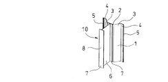
- a combination steel sheet pile in which a shape steel such as an H-shaped steel or a T-shaped steel is fixed and stiffened to the steel sheet pile, and a combination steel sheet pile wall using this combination steel sheet pile is known (for example, Patent Documents 1 and 2). For example, as shown in FIG.
- the steel sheet pile main body (hat-shaped steel sheet pile) 1 is provided with a web 2 and flanges 3 provided on the left and right side edges thereof so as to extend diagonally to the web 2 respectively;
- the front end portion of the flange 3 is provided with an arm 4 provided substantially parallel to the web 2 and a joint 5 provided at the front end of each of the two arms 4.
- the web 2 of the steel sheet pile body 1 is assembled by welding both side edges of one flange 7 of an H-shaped steel 8 provided with flanges 7 at right angles to the web 6 at both ends of the web 6 respectively.
- the steel sheet pile 9 is configured.
- the resistance of the ground becomes large when the steel sheet sheet is welded to the steel sheet pile body 1 and buried in the ground.
- the combined steel sheet pile 9 has a bulky shape as compared with the case of the steel sheet pile body 1 alone. There is a problem that the number that can be done is limited and transport efficiency is poor.
- steel sheet pile body 1 and H-section steel 8 can be constructed separately.
- the steel 8 and the steel sheet pile main body 1 can be packed separately to improve the transportation efficiency, or the ground resistance can be reduced when the steel sheet pile main body 1 and the H-shaped steel 8 are driven or press-fitted.
- the combination steel sheet pile wall according to claim 1 has a steel sheet pile main body and a length which is disposed substantially in contact with the steel sheet pile main body and arranged along the axial direction of the steel sheet pile main body.
- a combined steel sheet pile wall constructed by continuously arranging the steel sheet pile body and the adjacent steel sheet pile body via a joint comprising: The steel sheet pile body and the stiffener are not fixed over substantially the entire length, The stiffener is disposed on the side of the relatively high ground pressure side of the two sections separated by the continuously arranged steel sheet pile body, The stiffener is provided between a sheet pile contact portion substantially in contact with the steel sheet pile body, an earth pressure receiving portion provided at a position separated from the sheet pile contact portion, and the sheet pile contact portion and the earth pressure receiving portion.
- a connecting portion for connecting the sheet pile contacting portion and the earth pressure receiving portion is provided, and the lateral width of the earth pressure receiving portion is wider than the lateral width of the sheet pile contacting portion.
- the lateral width of the earth pressure receiving portion of the stiffener is such that the steel stiffener having the earth pressure receiving portion and the steel sheet pile main body can be equally bent.
- the steel sheet pile main body is not separated from the stiffener by the earth pressure because the soil pressure is wider than the lateral width of the sheet pile contact portion of the stiffener so that the earth pressure acts on the earth pressure receiving portion, and the steel sheet pile It becomes possible to make the deflection behavior of the main body and the stiffener the same.
- the combination steel sheet pile wall according to claim 2 is the steel sheet pile wall according to claim 1, wherein the stiffener is made of an H-shaped steel, and one flange of the H-shaped steel is used as the sheet pile contact portion, The other flange is an earth pressure receiving portion, the web is a connecting portion, and the width of the other flange is wider than the one flange.
- H-shaped steels having different flange widths are used as the stiffeners.
- the combination steel sheet pile wall according to claim 3 is the steel sheet pile wall according to claim 1, wherein the stiffener includes a sheet pile contact member and a earth pressure receiving member, and the sheet pile contact member is the sheet pile contact. A portion and a connection portion, wherein the earth pressure receiving member comprises the earth pressure receiving portion.
- a shaped steel such as H-shaped steel, I-shaped steel or grooved steel is used as a sheet-laying contact member, and this is brought into contact with the steel sheet pile main body.
- a stiffener can be provided by attaching (contacting) a wide earth pressure receiving member to the shape steel, that is, by combining a wide earth pressure receiving member with a normal shape steel.
- the combination steel sheet pile wall according to claim 4 is the steel sheet pile wall according to claim 3, wherein the sheet pile contact member is an H-shaped steel, and the earth pressure receiving member is any one of a steel plate, a section steel or a steel sheet pile. It is characterized by being.
- an H-shaped steel widely used as a construction material and capable of easily procuring various sizes, strengths, etc. is used as a sheet pile contact member of a stiffener, and By providing the members separately from the flanges of the H-shaped steel, for example, even if the width of the pair of flanges does not provide the H-shaped steels different from each other by processing one of the flanges of the H-shaped steel, On the other hand, the width of the earth pressure receiving member can be increased.
- the steel plate may be a flat steel as a shaped steel.
- the combination steel sheet pile wall according to claim 5 is the steel sheet pile wall according to any one of claims 1 to 4, wherein the lateral width of the earth pressure receiving portion is equal to or less than the effective width of the steel sheet pile main body. It is characterized by being.
- the lateral width of the earth pressure receiving portion equal to or less than the effective width of the steel sheet pile body, the amount of steel material used can be reduced and the cost can be reduced.
- the adjacent earth pressure receivers do not necessarily have to be in contact with each other or partially overlapped, and may be spaced to some extent.
- the effective width of a steel sheet pile main body remove excludes the half width of the part which overlaps with the coupling of the steel sheet pile main body which adjoins right and left from the left-right width of a steel sheet pile main body.
- the lateral width X of the earth pressure receiving portion satisfies the condition of the following expressions (a) and (b) It features.
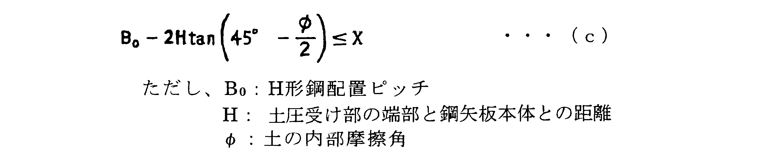
- the combination steel sheet pile wall according to claim 7 is characterized in that, in the combination steel sheet pile wall according to claim 5, the lateral width X of the earth pressure receiving portion satisfies the condition of the following expression (c).
- the ends of adjacent earth pressure receiving portions are in contact with each other. It is considered that the earth pressure can be applied so that the stiffener and the steel sheet pile body bend more equally, even if they do not overlap or partially overlap.
- the steel sheet pile body and the stiffening member are fixed over substantially the entire length. Even if the stiffener is placed on the side of the steel sheet pile wall that receives the earth pressure or on the side where the earth pressure is relatively high, the steel sheet will not be pulled away from the stiffener by the earth pressure, and the lap beam Cross section rigidity can be improved as a formula combination steel sheet pile wall.
- FIG. 1 is a view showing a first embodiment of the present invention.
- the combined steel sheet pile wall 26 of this example functions as a stiffener for stiffening the steel sheet pile main body 1 and the steel sheet pile main body 1 in the same manner as the conventional one.
- the H-shaped steels 24 have different right and left widths 23.
- the steel sheet pile body 1 includes the web 2, the flange 3, the arm 4 and the joint 5, and is connected to the adjacent steel sheet pile body 1 via the joint 5.
- the H-shaped steel 24 is provided with a narrow flange 22 with a horizontal width (flanging width) relatively to each end of the web 25 and a flange 23 with a horizontal width wider than the flange 22.
- the narrow flange 22 has a width slightly smaller than the lateral width of the web 2 of the steel sheet pile body 1 and is a sheet-board contact portion to be brought into contact with the web 2.
- the narrow flange 22 is in contact with the web 2 at the surface on the valley side (concave side) of the steel sheet pile body 1.
- the lateral width of the narrow flange 22 is the right and left width of the web 2 of the steel sheet pile body 1. It may be wider than the width.
- the H-shaped steel 24 is disposed on the side where the earth and sand are supported as the earth retaining wall against the steel sheet pile main body 1 and the earth pressure (shown by the arrow in the drawing) is applied. Ru.
- the wide flange 23 is disposed on the side away from the steel sheet pile body 1 with the narrow flange 22 in contact with the steel sheet pile body 1. That is, the wide flange 23 is an earth pressure receiving portion mainly receiving earth pressure in the H-shaped steel 24 as a stiffener.
- the web 25 of the H-shaped steel 24 functions as a connection part which connects the flange 22 as a sheet-sheet contact part, and the flange 23 as an earth pressure receiving part.
- the combined steel sheet pile wall 26 embeds the steel sheet pile body 1 in the ground so that the steel sheet pile bodies 1 are connected to each other via the joints 5 (drilled, press-fit, etc.) as with ordinary steel sheet pile walls. It is constructed by embedding the H-shaped steel 24 for each steel sheet pile main body 1. Then, the plurality of steel sheet pile bodies 1 are connected, and the outer surface of the narrow flange 22 of the H-shaped steel 24 is in contact with the web 2 of each steel sheet pile body 1 on the same side of the steel sheet pile wall 26 It has become.
- the steel sheet pile main body 1 and the H-shaped steel 24 may be separately embedded, or the steel sheet pile main body 1 and the H-shaped steel 24 may be integrally embedded. .
- one H-shaped steel 24 may be repeatedly embedded after embedding one steel sheet pile main body 1, or a plurality of H-shaped steels 24 may be embedded after embedding a plurality of steel sheet pile main bodies 1. May be embedded in order.
- the steel sheet pile main body 1 and the H-shaped steel 24 are basically not joined, but one end may be joined or engaged, and in particular, the steel sheet pile main body 1 and the H-shaped steel 24 are integrated.
- the lower end sides of the steel sheet pile body 1 and the H-shaped steel 24 may be joined to each other when the steel sheet pile body 1 and the H-shaped steel 24 are driven or pressed into the ground.
- the steel sheet pile main body 1 is disposed on the side where the earth pressure is not applied (the side where the earth pressure is relatively low), and the H-section steel 24 is the side where the earth pressure is applied Placed on the high side).
- the excavated area side is earth pressure It is the side where it does not take, and the area side which is not excavated is the side where the earth pressure is applied.
- earth and sand are filled One area side to be treated is the earth pressure side, and the other area side is the earth pressure side.
- earth pressure mainly acts on the H-section steel 24 from the wide flange 23, and in the steel sheet pile main body 1, earth pressure is applied to the steel sheet pile main body 1 from between the adjacent H-shaped steels 24. It will work.
- the received earth pressure becomes large, and in the steel sheet pile main body 1, the earth pressure received by being blocked by the wide flange 23 becomes small.
- the H-section steel 24 is pressed against the steel sheet pile main body 1 by the earth pressure, and the steel sheet pile main body 1 and the H-section steel The state of contact with H.24 is maintained, and the deflection behavior of the steel sheet pile body 1 and the H-shaped steel 24 match.
- the width of the flange 23 is insufficient, the deformation of the steel sheet pile body 1 due to the earth pressure becomes larger than the deformation due to the earth pressure applied to the H-shaped steel 24, and the steel sheet pile body 1 and the H-shaped steel 24 They are separated by earth pressure, and the deflection behavior of the steel sheet pile body 1 and the H-shaped steel 24 do not match and does not function as a lap beam.
- the width of the flange 23 is set so that the deformation of the steel sheet pile main body 1 due to the earth pressure does not become larger than the deformation of the H-shaped steel 24 due to the earth pressure. That is, the width of the flange 23 is set so that the steel sheet sheet main body 1 is not separated from the H-shaped steel 24 by the earth pressure.
- the width of such a flange 23 is calculated or experimentally determined based on the strength of the steel sheet pile body 1 and the H-shaped steel 24 based on the shape, size, thickness, material, etc. of the steel sheet pile body 1 and the conditions of earth and sand constituting the ground.
- the width of the adjacent flanges 23 exceeds the effective width of the steel sheet pile body 1, the flanges 23 are in contact with each other, and the rear side of the steel sheet pile body 1 is completely covered. In this case, earth pressure is not directly applied to the steel sheet pile body 1 side, and the steel sheet pile body 1 does not separate from the H-shaped steel 24.
- the width of the wide flange 23 be equal to or less than the effective width of the steel sheet pile main body 1 because a steel material more than necessary is used.
- the H-section steel 24 is not fixed to the steel sheet pile main body 1 by welding or the like. Even if the steel sheet pile body 1 does not separate from the H-section steel 24 even if it is arranged on the side where pressure is applied or the earth pressure becomes relatively high, the deflection behavior of the H-section steel 24 and the steel sheet pile body 1 is Match As a result, the combined steel sheet pile wall 26 functions as a pile beam to support the earth pressure by the steel sheet pile body 1 and the H-section steel 24. Therefore, the deformation amount due to the earth pressure than the steel sheet pile wall consisting of the steel sheet pile body 1 Can be made smaller.
- the geometrical moment of inertia a which is an amount representing the inflexibility of the deformation of the object with respect to the bending moment of the combined steel sheet pile 26, is used when the steel sheet pile body 1 and the H-section steel 24 function as a lap beam.
- the H-shaped steel 24 is disposed on the surface on the valley side of the steel sheet pile main body 1, but the H-shaped steel 24 may be disposed on the side surface on the mountain side (see FIG. 2).
- the connecting direction of the steel sheet pile 1 is more than the case where the H-shaped steel 24 is disposed on the valley side of the steel sheet Length), that is, the length (thickness) along the direction orthogonal to the extending length direction of the combined steel sheet pile wall 26 is increased. Therefore, the placement space can be smaller if the H-shaped steel 24 is disposed on the surface on the valley side of the steel sheet pile body 1.
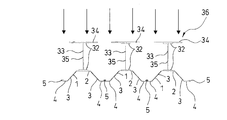
- the combined steel sheet pile wall 36 of this example is a H-shaped steel sheet having a hat-shaped steel sheet pile main body 1 similar to that of the first embodiment and a general shape having equal widths of a pair of flanges 32. It is comprised from 33 and the steel plate 34 used as a earth pressure receiving member.
- the steel plate 34 may be a flat steel as a shaped steel.
- one flange 32 of the H-shaped steel 33 which is a sheet-board contact member, is brought into contact with the web 2 of the steel sheet pile body 1 and the other steel plate 34 wider than the flange 32 has earth pressure. It is attached as a receiving member.
- one flange 32 in contact with the steel sheet pile body 1 of the H-shaped steel 33 is a sheet pile contact portion
- the steel plate 34 is an earth pressure receiving portion
- the other flange 32 to which the H-shaped steel web 35 and the steel plate 34 are attached Acts as a connection.
- the narrow flange 22 is used as a sheet-board contact portion and the wide flange 23 receives earth pressure.
- the steel plate 34 is used as the earth pressure receiving portion (earth pressure receiving member) by attaching the steel plate 34 wider than the flange 32 to the other flange 32 in the second embodiment.
- the steel plate 34 has an elongated structure similar to the steel sheet pile body 1 and the H-shaped steel 33, and has substantially the same length as the H-shaped steel 33.
- the left-right width orthogonal to the length direction of the steel plate 34 is determined similarly to the left-right width of the wide flange 23 of 1st Embodiment.
- the lateral width of the flange 32 of the H-shaped steel 33 is slightly shorter than the lateral width of the web 2 of the steel sheet pile main body 1 similarly to the narrow flange 22 of the H-shaped steel 24 of the first embodiment.
- the steel sheet pile main body 1, the H-shaped steel 33, and the steel plate 34 may be integrally constructed, or may be constructed separately, or the steel sheet pile main body 1 is constructed.
- the H-shaped steel 33 and the steel plate 34 may be integrally constructed separately from these, or the steel sheet pile main body 1 and the H-shaped steel 33 are integrally constructed, and the steel plate 34 is separately constructed separately from these. It is also good.
- the order of construction of each member is arbitrarily decided with respect to these constructions.
- the combined steel sheet pile wall 36 of the second embodiment exhibits the same effects as the combined steel sheet pile wall 26 of the first embodiment.
- a member other than the H-shaped steel 24 is not required as a stiffening material, and the H-shaped steel 24 having a shape different from that of a general H-shaped steel is required.
- the steel plate 34 is required in addition to the H-shaped steel 33 as a stiffening material, but the H-shaped steel 33 can be used in a general shape.
- the H-shaped steel 33 is disposed on the surface on the mountain side of the steel sheet pile body 1, but the placement of the H-shaped steel 33 on the surface on the valley side of the steel sheet pile body 1 is a placement space. Can be small. Also, the method of joining the other flange 32 of the H-shaped steel 33 and the steel plate 34 can be performed by, for example, coping, welding, a bolt, a drill screw, or some combination of these. Further, the H-shaped steel 33 and the steel plate 34 do not need to be joined over substantially the entire length, and for example, only the upper end or the lower end may be joined. Also, the H-shaped steel 33 and the steel plate 34 may not be joined.
- the coping is a steel sheet pile type quaywall, which is a concrete in which the steel sheet pile head is rolled and cast, and the steel sheet pile main body 1, the H-shaped steel 33 and the steel plate 34 are joined by this concrete.
- the geometrical moment of inertia in the combined steel sheet pile wall 36 of the second embodiment can be determined by adding together the geometrical moment of inertia of the steel sheet pile body 1, the H-shaped steel 33 and the steel plate 34.
- the combined steel sheet pile wall 47 of this example includes the steel sheet pile main body 1 similar to the second embodiment, the H-shaped steel 33 as a sheet pile contact member similar to the second embodiment, and earth pressure It replaces with the steel plate of 2nd Embodiment as a receiving member, and consists of a steel sheet pile 42 for stiffening.
- the stiffening steel sheet pile 42 is provided with a web 43, a flange 44 provided on the left and right side edges thereof so as to extend diagonally with respect to the web 43, respectively, and a joint 45 provided at the tip of the flange 44.
- U-shaped steel sheet pile since it is not necessary to connect and use the steel sheet for reinforcement 42, the joint 45 may not be necessary.
- one flange 32 in contact with the steel sheet pile body 1 of the H-section steel 33 which is a sheet-laying contact member is a sheet pile contact portion
- the steel sheet pile for stiffening 42 is in contact with the other flange 32 of the H-section steel 33.
- the connection portion is the earth pressure receiving portion
- the lateral width of the stiffening steel sheet pile 42 as the earth pressure receiving member is wider than the lateral width of the one flange 32 of the H-shaped steel 33 as the sheet-sheet contacting portion.
- the lateral width of the flange 32 of the H-shaped steel 33 is slightly narrower than the lateral width of the web 2 of the steel sheet pile main body 1 and the web 43 of the stiffening steel sheet pile 42. Further, one flange 32 of the pair of flanges 32 of the H-shaped steel 33 contacts the valley side of the steel sheet pile body 1, and the other flange 32 contacts the valley side of the stiffening steel sheet pile 42. There is.
- the combination steel sheet pile wall 47 of the third embodiment is obtained by replacing the steel plate 34 in the combination steel sheet pile wall 36 of the second embodiment with a steel sheet pile 42 for stiffening, and the combination is performed in the same manner as in the second embodiment.
- the steel sheet pile wall 47 can be constructed, and the same function and effect as the combined steel sheet pile wall 36 of the second embodiment can be obtained.
- the lateral width of the stiffening steel sheet pile 42 can be determined in the same manner as the lateral width of the wider flange 23 of the H-shaped steel 24 of the first embodiment.
- FIG. 4 to 6 show modifications of the combined steel sheet pile wall 47 of the third embodiment.
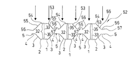
- the combination steel sheet pile wall 52 as a modification shown in FIG. 4 uses a hat-shaped stiffening steel sheet pile 53 in place of the U-shaped stiffening steel sheet pile 42 of the third embodiment, and for stiffening. One joint of the steel sheet pile 53 is eliminated.
- the other configuration is the same as that of the third embodiment.
- the stiffening steel sheet pile 53 is provided with a web 54, a flange 55 and an arm 56 substantially the same as the hat-shaped steel sheet pile main body 1, one arm 56 is provided with a joint 57, and the other arm 56 is provided.
- the joint 57 is not provided. Cost reduction can be achieved by not providing one joint 57 not used for joining. In addition, both joints 57 may not be provided.
- While the combination steel sheet pile wall 62 as a modification shown in FIG. 5 is in contact with the flange 32 of the H-shaped steel 33 at the valley side of the steel sheet pile 42 for stiffening in the third embodiment shown in FIG.
- the flange 32 of the H-shaped steel 33 is in contact with the mountain side of the stiffening steel sheet pile 42, and the other configuration is the same as that of the third embodiment.
- the combination steel sheet pile wall 72 as a modification shown in FIG. 6 is replaced with the U-shaped steel reinforcement sheet pile 42 of the third embodiment and, similarly to the steel reinforcement sheet pile 53 shown in FIG.
- the H-shaped steel 33 flange 34 is in contact with the mountain side of the stiffening steel sheet pile 42 by using a hat-shaped stiffening steel sheet pile 53 without a bolt, and the other configuration is the same as that of the third embodiment. It has the composition of In addition, it is preferable to make H-shaped steel 33 contact the valley side of the steel sheet pile 53 for stiffening space-efficiently as mentioned above.
- the combined steel sheet pile wall 86 of this example is a steel sheet pile main body 1 similar to the first embodiment, an H-shaped steel 33 similar to the second embodiment, and a second earth pressure receiving member.
- the steel plate 34 of the embodiment is composed of a stiffening H-shaped steel 82.
- the combination steel sheet pile wall 86 of the fourth embodiment can construct the combination steel sheet pile wall 86 in the same manner as the second embodiment, and the same action as the combination steel sheet pile wall 36 of the second embodiment. You can get the effect.
- the width of the web 83 of the H-shaped steel 82 can be determined in the same manner as the width of the wide flange 23 of the H-shaped steel 24 of the first embodiment.
- FIG. 8 shows a modification of the combined steel sheet pile wall 86 of FIG.
- the combination steel sheet pile wall 86 shown in FIG. 7 brings the web 83 of the stiffening H-shaped steel 82 into contact with the other flange 32 of the H-shaped steel 33 to press the web 83 of the stiffening H-shaped steel 82
- the combined steel sheet pile wall 96 of FIG. 8 brings one flange 94 of the stiffening H-shaped steel 92 into contact with the other flange 32 of the H-shaped steel 33 to make the stiffening H-shaped steel
- One flange 94 and the other flange 94 of 92 are earth pressure receiving members.
- the stiffening H-shaped steel 92 comprises a web 93 and flanges 94 respectively provided at both ends thereof.
- the flange 94 of the stiffening H-shaped steel 92 as the earth pressure receiving member is wider than the flange 32 of the H-shaped steel 33 as the sheet-sheet contacting member. Also in this modification, the same operation and effect as those of the above-described fourth embodiment can be obtained.
- the width of the flange 94 of the stiffening H-shaped steel 92 can be determined in the same manner as the width of the wider flange 23 of the H-shaped steel 24 of the first embodiment.
- the combined steel sheet pile wall 64 of this example is a general shape of H having a U-shaped steel sheet pile main body 65 and a pair of flanges 32 having the same width as in the second embodiment. It comprises a shaped steel 33 and a steel plate 34 serving as a ground pressure receiving member. Moreover, in this example, the steel sheet pile main body is stiffened every other sheet.
- the combined steel sheet pile wall 67 of this example is an H-shaped steel sheet pile main body 68 and H having a general shape in which the width of a pair of flanges 32 is equal to each other as in the second embodiment. It comprises a shaped steel 33 and a steel plate 34 serving as a ground pressure receiving member.
- the flange 32 which is a sheet-sheet-contacting portion of the H-shaped steel 33, is in contact with the steel sheet pile body 68 at the connection portion of the joints 69a and 69b of the adjacent steel sheet pile body 68.
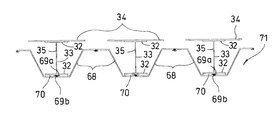
- the combined steel sheet pile wall 71 of this example is a general shape of H in which the width of the pair of flanges 32 is the same as that of the Z-shaped steel sheet pile main body 68 and the second embodiment. It comprises a shaped steel 33 and a steel plate 34 serving as a ground pressure receiving member.
- the flange 32 which is a sheet-sheet-contacting portion of the H-shaped steel 33, is brought into contact with the steel sheet pile body via the spacer 70 at the connection portion of the joints 69a and 69b of the adjacent steel sheet pile body 68.
- the stiffener is disposed on the side of the various steel sheet piles on which the earth pressure is applied (the side where the earth pressure increases), the earth pressure receiving portion (earth pressure receiver) having wide lateral width in the stiffener
- the stiffeners are subjected to a large earth pressure, and the deflection behavior of the steel sheet pile and the stiffeners becomes almost the same, and it is possible to increase the second moment of area of the combined steel sheet pile.
- all steel sheet pile bodies are stiffened except for FIG. 9, but if the cross-sectional performance of the steel sheet pile wall is acceptable, for example, every other steel sheet pile body Not all the steel sheet pile bodies constituting the steel sheet pile wall may be stiffened.
- the calculation method is demonstrated based on FIGS. 12-15 about the preferable left-right width (lower limit value) of the earth pressure receiving part (earth pressure receiving member).
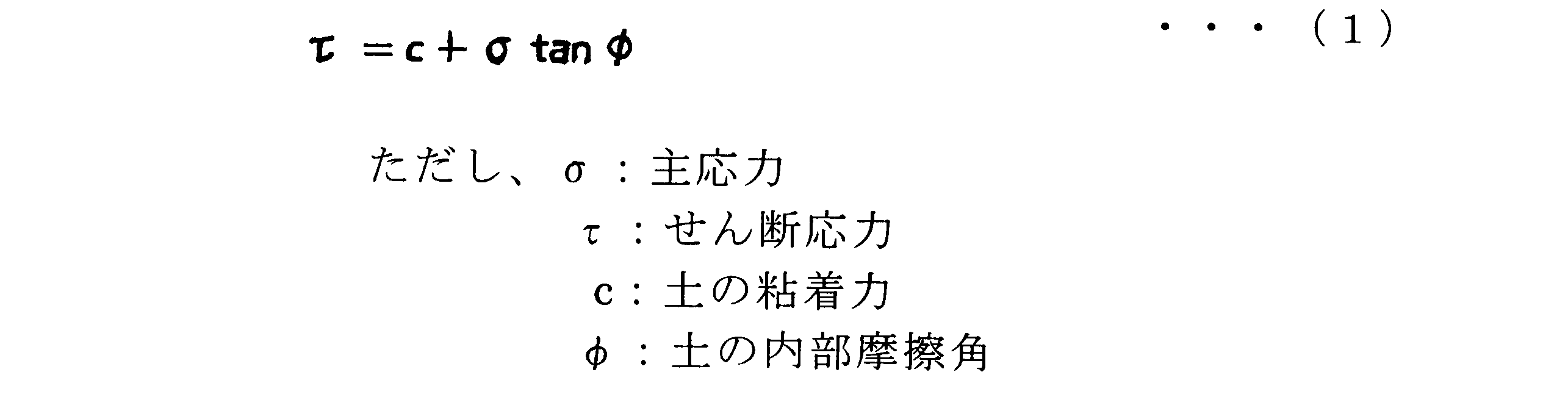
- the principal stress ⁇ and shear stress ⁇ on any surface AB are ⁇ , ⁇ on the stress circle of the molding in FIG. 12 (b). It becomes the value of.
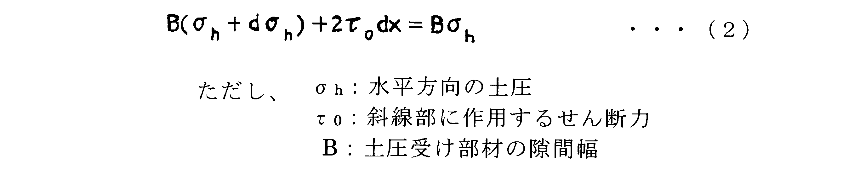
- equation (1) acts in shear force ⁇ 0 in equation (2)
- equation (3) holds, and equations (2) and (3)
- equation (4) holds.
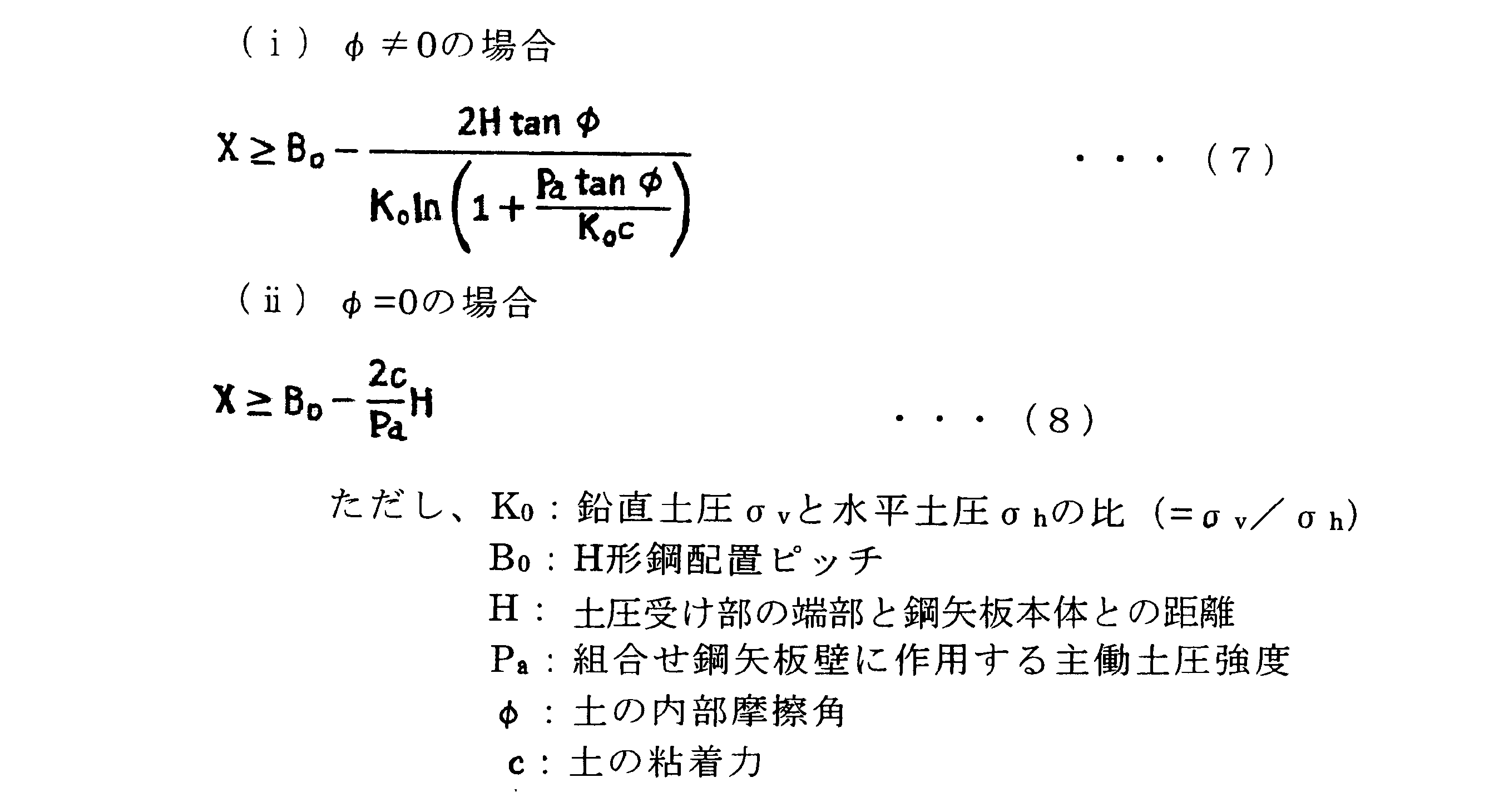
- the earth pressure receiving portion is in the range shown by the equations (7) and (8), the earth pressure does not act directly on the steel sheet pile body, and the deflection behavior of the steel sheet pile body and the stiffener Are considered to be regarded as a combination steel sheet pile of the lap beam type.
- Reference 1 proposes a method for evaluating the tensile strain when a local subsidence of the base occurs for a geomembrane to be laid in a waste disposal site.
- the strain of the geomembrane is calculated assuming the slip surface of the sand layer in the following equation (9) (see FIG. 1 of reference 1 and equation (15) on p. 42).
- the earth pressure does not act directly on the sheet pile, and the deflection behavior of the steel sheet pile main body and the stiffener match. It can be considered that it can be regarded as a beam-type combination steel sheet pile.
Landscapes
- Engineering & Computer Science (AREA)
- Structural Engineering (AREA)
- Chemical & Material Sciences (AREA)
- Composite Materials (AREA)
- Life Sciences & Earth Sciences (AREA)
- General Life Sciences & Earth Sciences (AREA)
- Mining & Mineral Resources (AREA)
- Paleontology (AREA)
- Civil Engineering (AREA)
- General Engineering & Computer Science (AREA)
- Bulkheads Adapted To Foundation Construction (AREA)
Abstract
Description
前記鋼矢板本体と前記補剛材とは略全長に渡る固定はされておらず、
前記補剛材は、前記連続配置した鋼矢板本体により仕切られた二つの区域のうちの相対的に土圧の高い区域側に配置され、
前記補剛材は、前記鋼矢板本体に実質的に接触する矢板接触部と、前記矢板接触部から離れた位置に設けられる土圧受け部と、これら矢板接触部および土圧受け部の間にあってこれら矢板接触部および土圧受け部を接続された状態とする接続部とを備え、前記土圧受け部の左右幅が、前記矢板接触部の左右幅より広くなっていることを特徴とする。

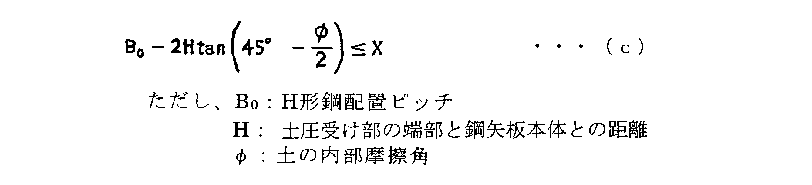
図1は、本発明の第1実施形態を示す図である。
図1に示すように、この例の組合せ鋼矢板壁26は、従来と同様のハット形の鋼矢板本体1と、鋼矢板本体1を補剛する補剛材として機能し、一対のフランジ22,23の左右幅が異なるH形鋼24とからなるものである。鋼矢板本体1は、上述のように、ウェブ2、フランジ3、アーム4および継手5を備えており、隣接する鋼矢板本体1と継手5を介して接続されている。H形鋼24は、ウェブ25の両端部にそれぞれ相対的に左右幅(フランジ幅)の狭いフランジ22と、このフランジ22より左右幅の広いフランジ23とを備えている。
なお、幅の狭いフランジ22を鋼矢板本体1の山側(凹側)の面でウェブ2に接触させる場合には、幅の狭いフランジ22の左右幅の方が鋼矢板本体1のウェブ2の左右幅より広くなってもよい。
なお、第1実施形態では、鋼矢板本体1の谷側となる面にH形鋼24を配置したが、山側となる側面にH形鋼24を配置してもよい(図2参照)。但し、鋼矢板本体1の谷側となる面にH形鋼24を配置した場合よりも、山側となる面にH形鋼24を配置した方が、鋼矢板本体1の接続方向(前記左右となる方向)、すなわち、組合せ鋼矢板壁26の延在する長さ方向と直交する方向に沿った長さ(厚さ)が長くなる。したがって、打設スペースは鋼矢板本体1の谷側となる面にH形鋼24を配置する方が小さくて済む。
図2に示すように、この例の組合せ鋼矢板壁36は、第1実施形態と同様のハット形の鋼矢板本体1と、一対のフランジ32の幅が互いに等しい一般的な形状のH形鋼33と、土圧受け部材となる鋼板34とから構成されている。なお、鋼板34は、形鋼としての平鋼であってもよい。第2実施形態においては、矢板接触部材であるH形鋼33の一方のフランジ32が鋼矢板本体1のウェブ2に接触させられ、他方のフランジ32にフランジ32より幅の広い鋼板34が土圧受け部材として取り付けられる。この構造ではH形鋼33の鋼矢板本体1に接触している一方のフランジ32が矢板接触部、鋼板34が土圧受け部、H形鋼のウェブ35および鋼板34が取り付けられる他方のフランジ32が接続部として機能する。
鋼板34は、鋼矢板本体1およびH形鋼33と同様に長尺な構造を有するもので、H形鋼33とほぼ同じ長さを有するものとなっている。
また、鋼板34の長さ方向と直交する左右幅は、第1実施形態の幅の広いフランジ23の左右幅と同様に決定される。
また、H形鋼33の他方のフランジ32と、鋼板34との接合方法は、例えば、コーピング、溶接、ボルト、ドリルねじのいずれか、またはこれらのうちのいくつかの組合せで行うことができる。また、H形鋼33と鋼板34とは、ほぼ全長に渡って接合する必要はなく、例えば、上端部もしくは下端部だけを接合するものであってもよい。また、H形鋼33と鋼板34とを接合しないものとしてもよい。なお、コーピングは、鋼矢板式岸壁で、鋼矢板頭部を巻き込んで打設するコンクリートであり、このコンクリートにより鋼矢板本体1、H形鋼33、鋼板34が接合された状態となる。
また、このような第2実施形態の組合せ鋼矢板壁36における断面二次モーメントは、鋼矢板本体1、H形鋼33および鋼板34それぞれの断面二次モーメントを足し合わせることにより求めることができる。
図3に示すように、この例の組合せ鋼矢板壁47は、第2実施形態と同様の鋼矢板本体1と、第2実施形態と同様の矢板接触部材としてのH形鋼33と、土圧受け部材として第2実施形態の鋼板に代えて補剛用鋼矢板42とからなるものである。この例で補剛用鋼矢板42は、ウェブ43と、その左右側縁にそれぞれウェブ43に対して斜めで互いに広がるように設けられたフランジ44と、フランジ44の先端部に設けられた継手45とからなるU形の鋼矢板である。なお、補剛用鋼矢板42は、接続して用いる必要はないので、継手45がなくてもよい。
なお、補剛用鋼矢板42としては、U形鋼矢板以外に、ハット形鋼矢板、直線形鋼矢板等を用いることが可能である。
図4に示す変形例としての組合せ鋼矢板壁52は、第3実施形態のU形の補剛用鋼矢板42に代えて、ハット形の補剛用鋼矢板53を用い、かつ、補剛用鋼矢板53のうちの一方の継手を無くしたものである。それ以外の構成については、第3実施形態と同様の構成を有するものとなっている。
図7に示すように、この例の組合せ鋼矢板壁86は、第1実施形態と同様の鋼矢板本体1と、第2実施形態と同様のH形鋼33と、土圧受け部材として第2実施形態の鋼板34に代えて補剛用H形鋼82とからなるものである。
図7に示す組合せ鋼矢板壁86は、補剛用H形鋼82のウェブ83を、H形鋼33の他方のフランジ32に接触させて、補剛用H形鋼82のウェブ83を土圧受け部材としたが、図8の組合せ鋼矢板壁96は、補剛用H形鋼92の一方のフランジ94を、H形鋼33の他方のフランジ32に接触させて、補剛用H形鋼92の一方のフランジ94と他方のフランジ94を土圧受け部材としたものである。この補剛用H形鋼92は、ウェブ93とその両端部にそれぞれ設けられたフランジ94とからなるものである。
本発明の第5実施形態を図9に基づいて説明する。
図9に示すように、この例の組合せ鋼矢板壁64は、U形の鋼矢板本体65と、第2の実施形態と同様の、一対のフランジ32の幅が互いに等しい一般的な形状のH形鋼33と、土圧受け部材となる鋼板34とから構成されている。またこの例では、鋼矢板本体が1枚おきに補剛されている。
図10に示すように、この例の組合せ鋼矢板壁67は、Z形の鋼矢板本体68と、第2の実施形態と同様の、一対のフランジ32の幅が互いに等しい一般的な形状のH形鋼33と、土圧受け部材となる鋼板34とから構成されている。H形鋼33の矢板接触部となるフランジ32は、隣接する鋼矢板本体68の継手69a、69bの接続部において鋼矢板本体68に接触される。
図11に示すように、この例の組合せ鋼矢板壁71は、Z形の鋼矢板本体68と、第2の実施形態と同様の、一対のフランジ32の幅が互いに等しい一般的な形状のH形鋼33と、土圧受け部材となる鋼板34とから構成されている。H形鋼33の矢板接触部となるフランジ32は、隣接する鋼矢板本体68の継手69a、69bの接続部においてスペーサー70を介して鋼矢板本体に接触される。
土塊内の任意の面での応力状態を示す基本的な表示となるものとして、図12に示す「モールの応力円」がある。図12(a)で示すように土塊に上下左右より応力が作用した場合、任意の面ABでの主応力σとせん断応力τは、図12(b)のモールの応力円上のσ,τの値となる。図13に示す式(1)のラインは、モール・クーロンの破壊基準と呼ばれ、土塊に作用する応力が大きくなり、破壊基準のラインに接すると土塊は破壊に至る。なお、このときの図12における破壊面角度θはθ=45°+φ/2となる。


[参考文献1:野本哲也,今泉繋良,阿部秀治,坪井正行,二見智子;基盤の局所沈下に伴う敷設高密度ポリエチレン(HDPE)ジオメンブレンの伸び挙動評価の模型実験,土木学会論文集No.652/lll-51,35-45,200.6]


22 フランジ(矢板接触部)
23 フランジ(土圧受け部)
24 H形鋼(補剛材、形鋼)
25 ウェブ(接続部)
26 組合せ鋼矢板壁
32 フランジ(矢板接触部、接続部)
33 H形鋼(形鋼、矢板接触部材)
34 鋼板(土圧受け部材)
35 ウェブ(接続部)
36 組合せ鋼矢板壁
42 補剛用鋼矢板(土圧受け部材)
47 組合せ鋼矢板壁
52 組合せ鋼矢板壁
53 補剛用鋼矢板(土圧受け部材)
62 組合せ鋼矢板壁
72 組合せ鋼矢板壁
82 補剛用H形鋼(土圧受け部材)
83 ウェブ(土圧受け部)
86 組合せ鋼矢板壁
92 補剛用H形鋼(土圧受け部材)
94 フランジ(土圧受け部)
96 組合せ鋼矢板壁
Claims (7)
- 鋼矢板本体と、当該鋼矢板本体に実質的に接触して当該鋼矢板本体の軸方向に沿って配置される長尺な補剛材とを備え、前記鋼矢板本体を隣接する前記鋼矢板本体と継手を介して連続して配置することで構築する組合せ鋼矢板壁であって、
前記鋼矢板本体と前記補剛材とは略全長に渡る固定はされておらず、
前記補剛材は、前記連続配置した鋼矢板本体により仕切られた二つの区域のうちの相対的に土圧の高い区域側に配置され、
前記補剛材は、前記鋼矢板本体に実質的に接触する矢板接触部と、前記矢板接触部から離れた位置に設けられる土圧受け部と、これら矢板接触部および土圧受け部の間にあってこれら矢板接触部および土圧受け部を接続された状態とする接続部とを備え、前記土圧受け部の左右幅が、前記矢板接触部の左右幅より広くなっていることを特徴とする組合せ鋼矢板壁。 - 前記補剛材はH形鋼からなり、当該H形鋼の一方のフランジが前記矢板接触部とされ、他方のフランジが土圧受け部とされ、ウェブが接続部とされ、前記一方のフランジより前記他方のフランジの幅が広くされていることを特徴とする請求項1に記載の組合せ鋼矢板壁。
- 前記補剛材は、矢板接触部材と土圧受け部材とを備え、前記矢板接触部材は前記矢板接触部および接続部を備え、前記土圧受け部材は前記土圧受け部を備えている請求項1に記載の組合せ鋼矢板壁。
- 前記矢板接触部材がH形鋼であり、前記土圧受け部材が鋼板、形鋼または鋼矢板のいずれかであることを特徴とする請求項3に記載の組合せ鋼矢板壁。
- 前記土圧受け部の左右幅は、前記鋼矢板本体の有効幅以下であることを特徴とする請求項1から請求項4のいずれか1項に記載の組合せ鋼矢板壁。
- 前記土圧受け部の左右幅Xは、次式(a)および(b)の条件を満たすことを特徴とする請求項5に記載の組合せ鋼矢板壁。

- 前記土圧受け部の左右幅Xは、次式(c)の条件を満たすことを特徴とする請求項5に記載の組合せ鋼矢板壁。
Priority Applications (3)
| Application Number | Priority Date | Filing Date | Title |
|---|---|---|---|
| JP2011549366A JP5177603B2 (ja) | 2010-04-22 | 2011-03-22 | 組合せ鋼矢板壁 |
| CN201180002854.8A CN102472032B (zh) | 2010-04-22 | 2011-03-22 | 组合钢板桩墙 |
| HK12110267.1A HK1169688B (en) | 2010-04-22 | 2011-03-22 | Combined steel sheet piling wall |
Applications Claiming Priority (2)
| Application Number | Priority Date | Filing Date | Title |
|---|---|---|---|
| JP2010099215 | 2010-04-22 | ||
| JP2010-099215 | 2010-04-22 |
Publications (1)
| Publication Number | Publication Date |
|---|---|
| WO2011132489A1 true WO2011132489A1 (ja) | 2011-10-27 |
Family
ID=44834025
Family Applications (1)
| Application Number | Title | Priority Date | Filing Date |
|---|---|---|---|
| PCT/JP2011/056712 Ceased WO2011132489A1 (ja) | 2010-04-22 | 2011-03-22 | 組合せ鋼矢板壁 |
Country Status (4)
| Country | Link |
|---|---|
| JP (1) | JP5177603B2 (ja) |
| CN (1) | CN102472032B (ja) |
| TW (1) | TWI441971B (ja) |
| WO (1) | WO2011132489A1 (ja) |
Cited By (5)
| Publication number | Priority date | Publication date | Assignee | Title |
|---|---|---|---|---|
| JP2015183475A (ja) * | 2014-03-25 | 2015-10-22 | Jfeスチール株式会社 | 土留め壁用鋼製部材および該土留め壁用鋼製部材を用いた合成構造壁 |
| JP2017172296A (ja) * | 2016-03-25 | 2017-09-28 | Jfeスチール株式会社 | 既設鋼矢板壁の補強構造及び補強方法 |
| JP2017180048A (ja) * | 2016-03-31 | 2017-10-05 | Jfeスチール株式会社 | 鋼矢板壁 |
| JP2017180046A (ja) * | 2016-03-31 | 2017-10-05 | Jfeスチール株式会社 | 既設鋼矢板壁の補強構造および補強工法 |
| JP2017198035A (ja) * | 2016-04-28 | 2017-11-02 | Jfeスチール株式会社 | 鋼矢板壁 |
Families Citing this family (8)
| Publication number | Priority date | Publication date | Assignee | Title |
|---|---|---|---|---|
| JP5769608B2 (ja) * | 2011-12-06 | 2015-08-26 | 日立造船株式会社 | 鋼板セル・アークの設置工法および鋼板セルの接続部構造 |
| SG11201800379XA (en) * | 2015-08-28 | 2018-02-27 | Nippon Steel & Sumitomo Metal Corp | Longitudinal joint structure for hat-type steel sheet piles, longitudinal joint hat-type steel sheet pile unit, and steel wall |
| CN106284297A (zh) * | 2016-10-13 | 2017-01-04 | 周峰 | 一种新型复合式钢板桩 |
| CN106703044B (zh) * | 2017-01-11 | 2018-03-02 | 北京建工土木工程有限公司 | 一种流塑状冲填土软弱地层放坡组合支护方法 |
| CN108729450A (zh) * | 2018-05-30 | 2018-11-02 | 中水电第十工程局(郑州)有限公司 | 一种管道工程钢板桩支护方法 |
| JP7490510B2 (ja) * | 2020-09-14 | 2024-05-27 | 鹿島建設株式会社 | 二重土留め壁の構築方法 |
| JP6940709B1 (ja) * | 2021-02-24 | 2021-09-29 | 哲 牧野 | 擁壁及びその築造方法 |
| CN115305919A (zh) * | 2022-07-06 | 2022-11-08 | 中煤浙江基础建设有限公司 | 一种基坑开挖土方防滑坡围护结构及其施工方法 |
Citations (2)
| Publication number | Priority date | Publication date | Assignee | Title |
|---|---|---|---|---|
| JPH0489103A (ja) * | 1990-07-31 | 1992-03-23 | Nippon Steel Corp | 連続継手型形鋼およびその圧延成形方法 |
| JP2009249885A (ja) * | 2008-04-04 | 2009-10-29 | Nippon Steel Corp | 既設の鋼矢板の補強方法及び構造、既設の鋼矢板の補強用部材 |
Family Cites Families (3)
| Publication number | Priority date | Publication date | Assignee | Title |
|---|---|---|---|---|
| JP2005299202A (ja) * | 2004-04-12 | 2005-10-27 | Nippon Steel Corp | 鋼矢板とそれを用いた土留め構造及び土留め構造の構築方法 |
| CN201400889Y (zh) * | 2009-03-12 | 2010-02-10 | 中船第九设计研究院工程有限公司 | 一种用于港湾码头或船坞的组合钢板桩及一体化直立墙 |
| JP4798251B2 (ja) * | 2009-04-21 | 2011-10-19 | 住友金属工業株式会社 | 組合せ鋼矢板および該組合せ鋼矢板を用いた鋼矢板壁 |
-
2011
- 2011-03-22 WO PCT/JP2011/056712 patent/WO2011132489A1/ja not_active Ceased
- 2011-03-22 CN CN201180002854.8A patent/CN102472032B/zh not_active Expired - Fee Related
- 2011-03-22 JP JP2011549366A patent/JP5177603B2/ja not_active Expired - Fee Related
- 2011-03-25 TW TW100110412A patent/TWI441971B/zh not_active IP Right Cessation
Patent Citations (2)
| Publication number | Priority date | Publication date | Assignee | Title |
|---|---|---|---|---|
| JPH0489103A (ja) * | 1990-07-31 | 1992-03-23 | Nippon Steel Corp | 連続継手型形鋼およびその圧延成形方法 |
| JP2009249885A (ja) * | 2008-04-04 | 2009-10-29 | Nippon Steel Corp | 既設の鋼矢板の補強方法及び構造、既設の鋼矢板の補強用部材 |
Cited By (5)
| Publication number | Priority date | Publication date | Assignee | Title |
|---|---|---|---|---|
| JP2015183475A (ja) * | 2014-03-25 | 2015-10-22 | Jfeスチール株式会社 | 土留め壁用鋼製部材および該土留め壁用鋼製部材を用いた合成構造壁 |
| JP2017172296A (ja) * | 2016-03-25 | 2017-09-28 | Jfeスチール株式会社 | 既設鋼矢板壁の補強構造及び補強方法 |
| JP2017180048A (ja) * | 2016-03-31 | 2017-10-05 | Jfeスチール株式会社 | 鋼矢板壁 |
| JP2017180046A (ja) * | 2016-03-31 | 2017-10-05 | Jfeスチール株式会社 | 既設鋼矢板壁の補強構造および補強工法 |
| JP2017198035A (ja) * | 2016-04-28 | 2017-11-02 | Jfeスチール株式会社 | 鋼矢板壁 |
Also Published As
| Publication number | Publication date |
|---|---|
| JP5177603B2 (ja) | 2013-04-03 |
| HK1169688A1 (en) | 2013-02-01 |
| CN102472032A (zh) | 2012-05-23 |
| TWI441971B (zh) | 2014-06-21 |
| TW201139790A (en) | 2011-11-16 |
| JPWO2011132489A1 (ja) | 2013-07-18 |
| CN102472032B (zh) | 2014-07-09 |
Similar Documents
| Publication | Publication Date | Title |
|---|---|---|
| JP5177603B2 (ja) | 組合せ鋼矢板壁 | |
| TWI433981B (zh) | Composite steel sheet pile and steel plate pile wall using the combined steel sheet pile | |
| JP4943218B2 (ja) | 地中連続壁用鋼材、地中連続壁および地中連続壁の構築方法 | |
| JP2005299202A (ja) | 鋼矢板とそれを用いた土留め構造及び土留め構造の構築方法 | |
| JP4903744B2 (ja) | 既設の鋼矢板の補強構造、既設の鋼矢板の補強用部材 | |
| CN102667000B (zh) | 钢管板桩接头构造、钢管板桩基础及钢管板桩基础的构建方法 | |
| CN104395531B (zh) | 组合钢制壁 | |
| JP5521277B2 (ja) | ハット形鋼矢板 | |
| JP5256180B2 (ja) | 鋼管矢板の継手構造および鋼管矢板基礎 | |
| JP6477586B2 (ja) | 鋼矢板壁 | |
| JP6714307B2 (ja) | 既設鋼矢板壁の補強工法 | |
| JPH07317087A (ja) | 鋼製壁と鉄筋コンクリート床版との接合構造 | |
| JP4754397B2 (ja) | H形鋼同士の接合構造および接合方法 | |
| JP5633524B2 (ja) | 鋼矢板地下壁構造 | |
| WO2012057359A1 (ja) | 鋼矢板及び該鋼矢板によって形成された鋼矢板壁 | |
| JP7156347B2 (ja) | 鋼製壁体と鉄筋コンクリート床版の接合構造 | |
| JP2013040553A (ja) | 鋼矢板及びこれを用いた壁体 | |
| JP6489055B2 (ja) | 既設鋼矢板壁の補強構造および補強工法 | |
| JP5370311B2 (ja) | 鋼管矢板、鋼管矢板の継手構造、鋼管矢板基礎、および鋼管矢板の製造方法 | |
| JP3573991B2 (ja) | 鋼管矢板及び鋼管矢板の連結構造 | |
| HK1169688B (en) | Combined steel sheet piling wall | |
| JP2026013011A (ja) | 合成壁構造、土留め壁用鋼製部材及び合成壁構造の構築方法 | |
| JP4798251B2 (ja) | 組合せ鋼矢板および該組合せ鋼矢板を用いた鋼矢板壁 | |
| JP2008121279A (ja) | 鋼矢板、及びその製造方法、並びに組合せ鋼矢板 | |
| JPH093878A (ja) | 土留め壁用建材及びその建込み方法 |
Legal Events
| Date | Code | Title | Description |
|---|---|---|---|
| WWE | Wipo information: entry into national phase |
Ref document number: 201180002854.8 Country of ref document: CN |
|
| WWE | Wipo information: entry into national phase |
Ref document number: 2011549366 Country of ref document: JP |
|
| 121 | Ep: the epo has been informed by wipo that ep was designated in this application |
Ref document number: 11771826 Country of ref document: EP Kind code of ref document: A1 |
|
| NENP | Non-entry into the national phase |
Ref country code: DE |
|
| 122 | Ep: pct application non-entry in european phase |
Ref document number: 11771826 Country of ref document: EP Kind code of ref document: A1 |