WO2011125977A1 - クリーニング方法、デバイス製造方法、露光装置、及びデバイス製造システム - Google Patents
クリーニング方法、デバイス製造方法、露光装置、及びデバイス製造システム Download PDFInfo
- Publication number
- WO2011125977A1 WO2011125977A1 PCT/JP2011/058520 JP2011058520W WO2011125977A1 WO 2011125977 A1 WO2011125977 A1 WO 2011125977A1 JP 2011058520 W JP2011058520 W JP 2011058520W WO 2011125977 A1 WO2011125977 A1 WO 2011125977A1
- Authority
- WO
- WIPO (PCT)
- Prior art keywords
- liquid
- cleaning
- supply
- exposure
- cleaning method
- Prior art date
- Legal status (The legal status is an assumption and is not a legal conclusion. Google has not performed a legal analysis and makes no representation as to the accuracy of the status listed.)
- Ceased
Links
Images










Classifications
-
- H—ELECTRICITY
- H10—SEMICONDUCTOR DEVICES; ELECTRIC SOLID-STATE DEVICES NOT OTHERWISE PROVIDED FOR
- H10P—GENERIC PROCESSES OR APPARATUS FOR THE MANUFACTURE OR TREATMENT OF DEVICES COVERED BY CLASS H10
- H10P76/00—Manufacture or treatment of masks on semiconductor bodies, e.g. by lithography or photolithography
- H10P76/20—Manufacture or treatment of masks on semiconductor bodies, e.g. by lithography or photolithography of masks comprising organic materials
- H10P76/204—Manufacture or treatment of masks on semiconductor bodies, e.g. by lithography or photolithography of masks comprising organic materials of organic photoresist masks
-
- G—PHYSICS
- G03—PHOTOGRAPHY; CINEMATOGRAPHY; ANALOGOUS TECHNIQUES USING WAVES OTHER THAN OPTICAL WAVES; ELECTROGRAPHY; HOLOGRAPHY
- G03F—PHOTOMECHANICAL PRODUCTION OF TEXTURED OR PATTERNED SURFACES, e.g. FOR PRINTING, FOR PROCESSING OF SEMICONDUCTOR DEVICES; MATERIALS THEREFOR; ORIGINALS THEREFOR; APPARATUS SPECIALLY ADAPTED THEREFOR
- G03F7/00—Photomechanical, e.g. photolithographic, production of textured or patterned surfaces, e.g. printing surfaces; Materials therefor, e.g. comprising photoresists; Apparatus specially adapted therefor
- G03F7/70—Microphotolithographic exposure; Apparatus therefor
- G03F7/70216—Mask projection systems
- G03F7/70341—Details of immersion lithography aspects, e.g. exposure media or control of immersion liquid supply
-
- G—PHYSICS
- G03—PHOTOGRAPHY; CINEMATOGRAPHY; ANALOGOUS TECHNIQUES USING WAVES OTHER THAN OPTICAL WAVES; ELECTROGRAPHY; HOLOGRAPHY
- G03F—PHOTOMECHANICAL PRODUCTION OF TEXTURED OR PATTERNED SURFACES, e.g. FOR PRINTING, FOR PROCESSING OF SEMICONDUCTOR DEVICES; MATERIALS THEREFOR; ORIGINALS THEREFOR; APPARATUS SPECIALLY ADAPTED THEREFOR
- G03F7/00—Photomechanical, e.g. photolithographic, production of textured or patterned surfaces, e.g. printing surfaces; Materials therefor, e.g. comprising photoresists; Apparatus specially adapted therefor
- G03F7/70—Microphotolithographic exposure; Apparatus therefor
- G03F7/708—Construction of apparatus, e.g. environment aspects, hygiene aspects or materials
- G03F7/70908—Hygiene, e.g. preventing apparatus pollution, mitigating effect of pollution or removing pollutants from apparatus
- G03F7/70925—Cleaning, i.e. actively freeing apparatus from pollutants, e.g. using plasma cleaning
Definitions
- the present invention relates to a cleaning method, a device manufacturing method, an exposure apparatus, and a device manufacturing system.
- This application is based on US provisional applications 61 / 320,451 and 61 / 320,469 filed April 2, 2010, and US application filed April 1, 2011. Claim the right and use it here.
- an immersion exposure apparatus that exposes a substrate with exposure light through an exposure liquid is used.
- the liquid contact member that comes into contact with the exposure liquid may be contaminated. Therefore, for example, a technique for cleaning the liquid contact member using a cleaning liquid as disclosed in the following patent document has been devised.
- An aspect of the present invention is to provide a cleaning method, a device manufacturing method, an exposure apparatus, and a device manufacturing system that can satisfactorily clean a liquid contact member and can smoothly perform processing of a liquid used for cleaning. .
- a cleaning method for a liquid contact member in contact with an exposure liquid in an exposure apparatus that exposes a substrate with exposure light through the exposure liquid, wherein the first liquid for cleaning is in contact with the exposure liquid.
- a cleaning method for a liquid contact member in contact with an exposure liquid in an exposure apparatus that exposes a substrate with exposure light through the exposure liquid, wherein the first liquid for cleaning is applied.
- Supplying the wetted member to clean the wetted member supplying the second liquid different from the first liquid to the wetted member and collecting after cleaning the wetted member with the first liquid;
- the second liquid is discharged from the first discharge port, and following the discharge from the first discharge port, the second liquid is discharged from a second discharge port different from the first discharge port;
- a cleaning method is provided.
- a cleaning method for a liquid contact member in contact with an exposure liquid in an exposure apparatus that exposes a substrate with exposure light through the exposure liquid, wherein the first liquid for cleaning is applied.
- Supplying the wetted member to clean the wetted member supplying the second liquid different from the first liquid to the wetted member and collecting after cleaning the wetted member with the first liquid; Performing the first process on the second liquid recovered in the first period of the recovery operation of the two liquids, and the second recovered in the second period of the recovery operation of the second liquid after the first period. Performing a second process different from the first process on the liquid.
- a cleaning method for a liquid contact member in contact with an exposure liquid in an exposure apparatus that exposes a substrate with exposure light through the exposure liquid, wherein the first cleaning liquid is applied to the liquid contact member.
- Cleaning the wetted member by supplying to the liquid, collecting the first cleaning liquid supplied to the wetted member and discharging it from the first outlet, and cleaning the wetted member with the first cleaning liquid Supplying a second cleaning liquid different from the first cleaning liquid to the liquid contact member to clean the liquid contact member, and collecting the second cleaning liquid supplied to the liquid contact member and discharging it from the second discharge port.
- the first and second liquids are suppressed so that the discharge of the first cleaning liquid from the second discharge port is suppressed. It supplies the different rinsing liquid wetted member and leaning liquid, and recovering the supplied rinse liquid, cleaning method comprising is provided.
- the liquid contact member is cleaned using the cleaning method of any one of the first to fourth aspects, the substrate is exposed via the exposure liquid, and the exposure is performed.
- a device manufacturing method is provided.
- an exposure apparatus for exposing a substrate with exposure light through an exposure liquid, wherein the liquid contact member that contacts the exposure liquid and the first liquid for cleaning are used as the liquid contact member.
- 2 supply ports and a second recovery port for recovering the second liquid supplied to the liquid contact member, and the concentration of the first liquid contained in the second liquid recovered from the second recovery port is a predetermined concentration or less.
- an exposure apparatus for exposing a substrate with exposure light through an exposure liquid, wherein the liquid contact member that contacts the exposure liquid and the first liquid for cleaning are used as the liquid contact member.
- a recovery port for recovering the liquid, and during the recovery of the second liquid, the second liquid is discharged from the first discharge port, and a second different from the first discharge port following the discharge from the first discharge port
- An exposure apparatus is provided in which the second liquid is discharged from the discharge port.
- an exposure apparatus for exposing a substrate with exposure light through an exposure liquid, wherein the liquid contact member that contacts the exposure liquid and the first liquid for cleaning are used as the liquid contact member.
- An exposure apparatus is provided in which a second process different from the first process is performed on the second liquid collected in the second period.
- an exposure apparatus that exposes a substrate with exposure light through an exposure liquid, the liquid contact member being in contact with the exposure liquid, and the first cleaning liquid being supplied to the liquid contact member.
- a first supply port, a first recovery port that recovers the first cleaning liquid supplied to the liquid contact member, and a second cleaning liquid that is different from the first cleaning liquid is supplied to the liquid contact member after the first cleaning liquid is supplied.
- First cleaning port a second recovery port for recovering the second cleaning liquid supplied to the liquid contact member, and a first cleaning from the discharge port for discharging the second cleaning liquid recovered from the second recovery port
- a third rinsing liquid different from the first and second cleaning liquids is supplied to the liquid contact member after the supply of the first cleaning liquid is stopped and before the supply of the second cleaning liquid is started so that the discharge of the liquid is suppressed.
- an exposure apparatus is provided comprising a third recovery port for recovering the rinse liquid supplied to the liquid contact member.
- a device manufacturing method comprising: exposing a substrate using the exposure apparatus according to any one of the sixth to ninth aspects; and developing the exposed substrate. Is provided.
- a device manufacturing system including an exposure apparatus that exposes a substrate with exposure light through an exposure liquid, wherein the liquid contact member in the exposure apparatus that contacts the exposure liquid is used for cleaning.
- a first supply port for supplying the first liquid, a first recovery port for recovering the first liquid supplied to the liquid contact member, and a second liquid different from the first liquid after the first liquid is supplied.
- a device manufacturing system including a processing apparatus that executes processing described below.
- a device manufacturing system including an exposure apparatus that exposes a substrate with exposure light through an exposure liquid, wherein the liquid contact member in the exposure apparatus that contacts the exposure liquid is used for cleaning.
- a first supply port for supplying the first liquid; a second supply port for supplying a second liquid different from the first liquid to the liquid contact member after the supply of the first liquid; and a second liquid supply from the second supply port.
- the recovery port for recovering the second liquid together with the supply, the first discharge port for discharging the second liquid recovered from the recovery port, and the second liquid recovered from the recovery port can be discharged.
- a second discharge port, and during the recovery of the second liquid the second liquid is discharged from the first discharge port, and the second liquid is discharged from the second discharge port following the discharge from the first discharge port.
- a device manufacturing system including an exposure apparatus that exposes a substrate with exposure light through an exposure liquid, wherein the liquid contact member in the exposure apparatus that contacts the exposure liquid is used for cleaning.
- a device manufacturing system includes a second processing apparatus that performs a second process different from the first process on the second liquid recovered in the second period of the second liquid recovery operation.
- a device manufacturing system including an exposure apparatus that exposes a substrate with exposure light through an exposure liquid, wherein a first cleaning is performed on a liquid contact member in the exposure apparatus that contacts the exposure liquid.
- a first supply port for supplying the liquid, a first recovery port for recovering the first cleaning liquid supplied to the liquid contact member, and a second cleaning liquid different from the first cleaning liquid after the first cleaning liquid is supplied.
- a cleaning method for a liquid contact member in contact with an exposure liquid in an exposure apparatus that exposes a substrate with exposure light through the exposure liquid, wherein the first liquid for cleaning is contacted.
- the wetted member is cleaned using the cleaning method of the first aspect, the substrate is exposed through the exposure liquid, and the exposed substrate is developed.
- a device manufacturing method is provided.
- an exposure apparatus that exposes a substrate with exposure light through an exposure liquid, wherein the liquid contact member that contacts the exposure liquid and the first liquid for cleaning are used as the liquid contact member.
- a device manufacturing method including exposing a substrate using the exposure apparatus according to the third aspect and developing the exposed substrate.
- a device manufacturing system including an exposure apparatus that exposes a substrate with exposure light through an exposure liquid, wherein the liquid contact member in the exposure apparatus that contacts the exposure liquid is used for cleaning.
- a device manufacturing system including a control device that stores the second liquid in the first storage member until the concentration of the first liquid contained in the second liquid in the storage member becomes equal to or lower than a predetermined concentration.
- the liquid contact member can be cleaned satisfactorily, and the liquid used for cleaning can be smoothly processed.
- an XYZ orthogonal coordinate system is set, and the positional relationship of each part will be described with reference to this XYZ orthogonal coordinate system.
- a predetermined direction in the horizontal plane is defined as an X-axis direction
- a direction orthogonal to the X-axis direction in the horizontal plane is defined as a Y-axis direction
- a direction orthogonal to each of the X-axis direction and the Y-axis direction (that is, a vertical direction) is defined as a Z-axis direction.
- the rotation (inclination) directions around the X axis, Y axis, and Z axis are the ⁇ X, ⁇ Y, and ⁇ Z directions, respectively.
- FIG. 1 is a schematic diagram illustrating an example of a device manufacturing system SYS according to the first embodiment.
- the device manufacturing system SYS includes a plurality of apparatuses.
- the device manufacturing system SYS includes an exposure apparatus EX that exposes a photosensitive substrate P with exposure light EL, a film formation apparatus that forms a photosensitive film on a base material of the substrate P, and a substrate P after exposure.
- a coater / developer apparatus CD including a developing apparatus for developing, a liquid system 100 capable of supplying a liquid used for manufacturing a device, a main controller MC for controlling the plurality of apparatuses, and a plurality of apparatuses And a communicable communication system CM.
- the communication system CM can communicate various types of information related to device manufacturing.
- the device manufacturing system SYS may include an etching apparatus, a CMP apparatus, and the like.
- the device manufacturing system SYS is installed in the factory FA.
- the device manufacturing system SYS may include a plurality of exposure apparatuses EX.
- FIG. 2 is a schematic block diagram that shows an example of the exposure apparatus EX according to the present embodiment.
- the exposure apparatus EX of the present embodiment is an immersion exposure apparatus that exposes a substrate P with exposure light EL through an exposure liquid LQ.
- the immersion space LS is formed so that at least a part of the optical path of the exposure light EL is filled with the exposure liquid LQ.
- the immersion space is a portion (space, region) filled with liquid.
- the substrate P is exposed with the exposure light EL through the exposure liquid LQ in the immersion space LS.
- water pure water
- the exposure apparatus EX of the present embodiment is an exposure apparatus that includes a substrate stage and a measurement stage as disclosed in, for example, US Pat. No. 6,897,963 and European Patent Application Publication No. 1713113. is there.
- the exposure apparatus EX measures the exposure light EL without holding the substrate P, the mask stage 1 that can move while holding the mask M, the substrate stage 2 that can move while holding the substrate P, and the like.
- a measuring stage 3 mounted with a measuring member C (measuring instrument) to be moved, an illumination system IL for illuminating the mask M with the exposure light EL, and an image of the pattern of the mask M illuminated with the exposure light EL are displayed on the substrate P
- a projection optical system PL that projects onto the projection surface, a liquid immersion member 7 that can form an immersion space LS so that the optical path K of the exposure light EL emitted from the projection optical system PL is filled with the exposure liquid LQ, and the entire exposure apparatus EX
- a control device 8 for controlling the operation.
- the mask M includes a reticle on which a device pattern projected onto the substrate P is formed.
- the mask M includes a transmission type mask having a transparent plate such as a glass plate and a pattern formed on the transparent plate using a light shielding material such as chromium.
- a reflective mask can also be used as the mask M.
- the substrate P is a substrate for manufacturing a device.
- a device pattern can be formed on the substrate P.
- the substrate P includes, for example, a base material such as a semiconductor wafer and a photosensitive film formed on the base material.
- the photosensitive film is a film of a photosensitive material (photoresist).
- the substrate P may include another film in addition to the photosensitive film.
- the substrate P may include an antireflection film or a protective film (topcoat film) that protects the photosensitive film.
- the illumination system IL irradiates the predetermined illumination area IR with the exposure light EL.
- the illumination area IR includes a position where the exposure light EL emitted from the illumination system IL can be irradiated.
- ArF excimer laser light is used as the exposure light EL emitted from the illumination system IL.
- KrF excimer laser light may be used as the exposure light EL.
- the mask stage 1 is movable on the guide surface 9G of the base member 9.
- the mask stage 1 has a holding portion 1H that holds the mask M so as to be releasable.
- the mask stage 1 can move the mask M held by the holding unit 1H to a position where the exposure light EL emitted from the illumination system IL can be irradiated.
- Projection optical system PL irradiates exposure light EL to a predetermined projection region PR.
- the projection optical system PL has an exit surface 13 that emits the exposure light EL toward the image plane of the projection optical system PL.
- the terminal optical element 12 closest to the image plane of the projection optical system PL has the exit surface 13.
- the projection region PR includes a position where the exposure light EL emitted from the emission surface 13 can be irradiated.
- the projection optical system PL projects an image of the pattern of the mask M at a predetermined projection magnification onto at least a part of the substrate P arranged in the projection region PR.
- the exposure light EL emitted from the emission surface 13 travels in the ⁇ Z direction.
- the optical axis of the last optical element 12 is parallel to the Z axis.
- the substrate stage 2 and the measurement stage 3 are movable on the guide surface 10G of the base member 10.
- the substrate stage 2 includes a substrate holding unit 11 that holds the substrate P in a releasable manner.
- the substrate stage 2 can move the substrate P held by the substrate holding unit 11 to a position where the exposure light EL emitted from the projection optical system PL can be irradiated.
- the measurement stage 3 has a holding portion 3H that holds the measurement member C so as to be releasable.
- the measurement stage 3 can move the measurement member C held by the holding unit 3H to a position where the exposure light EL emitted from the projection optical system PL can be irradiated.
- the substrate stage 2 is arranged around the substrate holding unit 11 as disclosed in, for example, US Patent Application Publication No. 2007/0177125 and US Patent Application Publication No. 2008/0049209. And a holding portion TH that holds the plate member T in a releasable manner.
- the plate member T is disposed around the substrate P held by the substrate holding unit 11.
- the measurement member C mounted on the measurement stage 3 may be a member constituting a part of an aerial image measurement system as disclosed in, for example, US Patent Application Publication No. 2002/0041377. Further, it may be a member constituting a part of an illuminance unevenness measuring system as disclosed in US Pat. No. 4,465,368 or the like, or a reference member as disclosed in US Pat. No. 5,493,403. Alternatively, it may be a member constituting a part of a dose measuring system as disclosed in US Patent Application Publication No. 2002/0061469, etc., or disclosed in European Patent No. 1079223. A member constituting a part of such a wavefront aberration measurement system may be used.
- the mask stage 1 can be moved by the operation of the drive system 4.
- the drive system 4 includes a planar motor having a mover 4 ⁇ / b> A disposed on the mask stage 1 and a stator 4 ⁇ / b> C disposed on the base member 9.
- the mask stage 1 can move in six directions on the guide surface 9G in the X axis, Y axis, Z axis, ⁇ X, ⁇ Y, and ⁇ Z directions by the operation of the drive system 4.
- Each of the substrate stage 2 and the measurement stage 3 can be moved by the operation of the drive system 5.
- the drive system 5 includes a planar motor having a mover 5A disposed on the substrate stage 2, a mover 5B disposed on the measurement stage 3, and a stator 5C disposed on the base member 10.
- Each of the substrate stage 2 and the measurement stage 3 can move in six directions on the guide surface 10G in the X axis, Y axis, Z axis, ⁇ X, ⁇ Y, and ⁇ Z directions by the operation of the drive system 5.
- An example of a flat motor is disclosed in, for example, US Pat. No. 6,452,292.
- the positions of the mask stage 1, the substrate stage 2, and the measurement stage 3 are measured by the interferometer system 6.
- the control device 8 When executing the exposure processing of the substrate P or when executing the predetermined measurement processing, the control device 8 operates the drive systems 4 and 5 based on the measurement result of the interferometer system 6 to thereby perform the mask stage 1 (mask M ), Position control of the substrate stage 2 (substrate P) and the measurement stage 3 (measurement member C) is executed.
- each of the upper surface 2F of the substrate stage 2 and the upper surface 3F of the measurement stage 3 is liquid repellent with respect to the exposure liquid LQ.
- the upper surface 2F includes the upper surface of the plate member T.
- the upper surfaces 2F and 3F are surfaces facing the + Z direction, and can face the terminal optical element 12 and the liquid immersion member 7.
- the upper surfaces 2F and 3F are formed of a film of a material containing fluorine.
- the immersion member 7 can form an immersion space LS so that the optical path K of the exposure light EL emitted from the emission surface 13 is filled with the exposure liquid LQ.
- the liquid immersion member 7 is disposed in the vicinity of the last optical element 12.
- the liquid immersion member 7 is an annular member and is provided so as to surround the terminal optical element 12.
- the liquid immersion member 7 has a lower surface 14 that can be opposed to an object disposed at a position (projection region PR) where the exposure light EL emitted from the last optical element 12 can be irradiated.
- the object that can be arranged in the projection region PR includes an object that can move on the image plane side of the projection optical system PL (the exit surface 13 side of the terminal optical element 12).
- the object includes at least one of a substrate stage 2, a substrate P held on the substrate stage 2, a dummy substrate DP described later, a measurement stage 3, and a measurement member C mounted on the measurement stage 3. .
- the last optical element 12 and the liquid immersion member 7 can hold the exposure liquid LQ with the object arranged in the projection region PR. At least a part of the emission surface 13 and the lower surface 14 is in contact with the exposure liquid LQ.
- the optical path K of the exposure light EL between the last optical element 12 and the object Is filled with the exposure liquid LQ.
- the immersion space LS is formed so that a partial region on the surface of the substrate P including the projection region PR is covered with the exposure liquid LQ.
- the liquid immersion member 7 holds the exposure liquid LQ in a local area smaller than the substrate P. At least a part of the interface (meniscus, edge) LGq of the exposure liquid LQ is formed between the lower surface 14 of the liquid immersion member 7 and the surface of the substrate P. That is, the exposure apparatus EX of the present embodiment employs a local liquid immersion method.
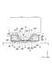
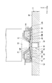
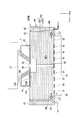
- FIG. 3 is a cross-sectional view parallel to the YZ plane showing an example of the liquid immersion member 7 according to this embodiment
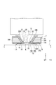
- FIG. 4 is a cross-sectional view parallel to the XZ plane
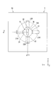
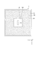
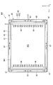
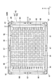
- FIG. 5 is a view of the liquid immersion member 7 according to the present embodiment as viewed from the upper side (+ Z side)
- FIG. 6 is a view as viewed from the lower side ( ⁇ Z side).
- 3 and 4 show a case where the substrate P is disposed at a position facing the terminal optical element 12 and the liquid immersion member 7, but as described above, for example, the substrate stage 2 and the measurement stage Other objects such as 3 may be arranged.
- the liquid immersion member 7 includes a plate portion 15 that is disposed around the optical path K of the exposure light EL that is emitted from the emission surface 13, and a main body portion 16 that is at least partially disposed around the terminal optical element 12. .
- the plate portion 15 has a lower surface 15B that can be opposed to the surface of the substrate P, and an upper surface 15A that faces the opposite direction of the lower surface 15B. At least a part of the upper surface 15A faces the emission surface 13.
- the liquid immersion member 7 has an opening (passage) 7K through which the exposure light EL emitted from the emission surface 13 can pass.
- the opening 7 ⁇ / b> K is formed in the plate portion 15.
- the opening 7K is formed so as to connect the upper surface 15A and the lower surface 15B.
- the lower surface 15B is disposed around the lower end of the opening 7K.
- the upper surface 15A is disposed around the upper end of the opening 7K.
- the exposure light EL emitted from the emission surface 13 can pass through the opening 7K and irradiate the substrate P.
- the liquid immersion member 7 includes a first supply port 21 that can supply the exposure liquid LQ and a recovery port 20 that can recover the exposure liquid LQ. At least during exposure of the substrate P, the first supply port 21 supplies the exposure liquid LQ, and the recovery port 20 recovers at least a part of the exposure liquid LQ supplied from the first supply port 21. In the exposure of the substrate P, the exposure liquid LQ is supplied from the first supply port 21 in a state where the substrate P is disposed facing the liquid immersion member 7.
- the liquid immersion member 7 has a second supply port 22 different from the first supply port 21.
- the second supply port 22 can supply a liquid different from the exposure liquid LQ.
- the second supply port 22 can supply a cleaning liquid LC for cleaning at least a part of the members in the exposure apparatus EX.
- the liquid immersion member 7 includes a first internal flow path 21R connected to the first supply port 21, a second internal flow path 22R connected to the second supply port 22, and a third internal flow connected to the recovery port 20. Road 20R.
- Each of the first internal flow path 21R, the second internal flow path 22R, and the third internal flow path 20R is formed inside the liquid immersion member 7.
- the first supply port 21 is formed at one end of the first internal channel 21R.
- the second supply port 22 is formed at one end of the second internal flow path 22R.
- the recovery port 20 is formed at one end of the third internal channel 20R.
- the first supply port 21 is disposed so as to face the optical path K in the vicinity of the optical path K of the exposure light EL.
- a plurality of first supply ports 21 are arranged.
- two first supply ports 21 are arranged.
- the first supply ports 21 are arranged on the + Y side and the ⁇ Y side with respect to the optical path K, respectively.
- the first supply port 21 supplies the exposure liquid LQ to the space SP1 between the emission surface 13 and the upper surface 15A.
- the exposure liquid LQ supplied from the first supply port 21 flows through the space SP1, it passes through the opening 7K and enters the space SP2 between the lower surface 15B (lower surface 14) and the surface of the substrate P (the upper surface of the object). Flowing.
- the second supply port 22 is disposed in the vicinity of the optical path K of the exposure light EL so as to face the optical path K.
- a plurality of second supply ports 22 are arranged.
- two second supply ports 22 are arranged.
- the second supply ports 22 are arranged on the + X side and the ⁇ X side with respect to the optical path K, respectively.
- the second supply port 22 can supply the cleaning liquid LC to the space SP1.
- the cleaning liquid LC supplied to the space SP1 flows to the space SP2 through the opening 7K.
- the number of the first supply ports 21 can be arbitrarily determined. Further, the position of the first supply port 21 with respect to the optical path K can be arbitrarily determined. Similarly, the number of the second supply ports 22 and the position of the second supply ports 22 with respect to the optical path K can be arbitrarily determined. For example, one or three or more of the first supply port 21 and the second supply port 22 may be arranged.
- the first supply port 21 may be disposed on at least one of the + X side and the ⁇ X side with respect to the optical path K.
- the second supply port 22 may be disposed on the + Y side and the ⁇ Y side with respect to the optical path K. It may be arranged in at least one of the above. Further, the position of the first supply port 21 in the Z direction may be different from the position of the second supply port 22 in the Z direction.
- the recovery port 20 can recover at least a part of the exposure liquid LQ on the substrate P (object).
- the recovery port 20 is disposed at a predetermined position of the liquid immersion member 7 that can face the surface of the substrate P.
- the recovery port 20 is disposed at least at a part around the lower surface 15B (opening 7K).
- the recovery port 20 is annular in the XY plane and is disposed around the lower surface 15B.
- a plurality of recovery ports 20 may be arranged at a predetermined interval so as to surround the lower surface 15B.
- the porous member 19 is disposed in the recovery port 20.
- the porous member 19 has a plurality of openings or pores.
- the porous member 19 is a plate-like member.
- the porous member 19 has a lower surface 19B that can be opposed to the surface of the substrate P, and an upper surface 19A that faces the opposite direction of the lower surface 19B.
- the hole 19H of the porous member 19 is formed so as to connect the upper surface 19A and the lower surface 19B.
- the lower surface 19 ⁇ / b> B of the porous member 19 is disposed around the lower surface 15 ⁇ / b> B of the plate portion 15.
- the lower surface 14 of the liquid immersion member 7 that can face the surface of the substrate P includes the lower surface 15B of the plate portion 15 and the lower surface 19B of the porous member 19.
- a mesh filter which is a porous member in which a large number of small holes are formed in a mesh shape, may be disposed in the recovery port 20. Further, the porous member 19 may not be disposed in the recovery port 20.
- the exposure liquid LQ (exposure liquid LQ on the object) in the space SP2 is recovered through the hole 19H of the porous member 19.
- the control device 8 determines that the pressure in the space SP2 that the lower surface 19B faces and the pressure in the space that the upper surface 19A faces (third internal flow path 20R). Adjust differently (generate differential pressure). Thereby, the exposure liquid LQ on the substrate P is recovered through the holes 19H of the porous member 19.
- the controller 8 executes the recovery operation of the exposure liquid LQ from the recovery port 20 in parallel with the supply operation of the exposure liquid LQ from the first supply port 21 in the exposure of the substrate P.
- an immersion space LS is formed with the exposure liquid LQ between the terminal optical element 12 and the liquid immersion member 7 on one side and the substrate P (object) on the other side.
- At least a part of the liquid immersion member 7 is formed of a material containing metal.
- at least a part of the liquid immersion member 7 is formed of a material containing titanium.
- the material containing titanium includes at least one of titanium and a titanium alloy.
- the plate part 15 and the main-body part 16 are formed with the material containing titanium.
- the porous member 19 is also formed of a material containing titanium.
- at least a part of the liquid immersion member 7 may include a material different from titanium, such as stainless steel and magnesium. Further, at least a part of the liquid immersion member 7 may be formed of a material containing ceramics.
- At least part of the surface of the liquid immersion member 7 may be formed of amorphous carbon.
- Amorphous carbon includes tetrahedral amorphous carbon.
- the plate portion 15 (base material) formed of a material containing titanium is formed, and at least one of the surfaces of the base material is formed.
- An amorphous carbon film is formed so that the portion is covered with the amorphous carbon film.
- at least a part of the upper surface 15A and the lower surface 15B is formed of amorphous carbon.
- At least a part of the upper surface 19A, the lower surface 19B, and the inner surface of the hole 19H of the porous member 19 may be formed of amorphous carbon.
- An amorphous carbon film can be formed (film formation) on the substrate by using a CVD method or a PVD method.
- At least a part of the surface of the liquid immersion member 7 may be formed of an oxide film.
- the oxide film may be titanium oxide.
- At least a part of the upper surface 19A, the lower surface 19B, and the inner surface of the hole 19H of the porous member 19 may be formed of an oxide film.
- liquid immersion member 7 for example, a liquid immersion member (nozzle member) as disclosed in US Patent Application Publication No. 2007/0132976 and European Patent Application Publication No. 1768170 can be used.
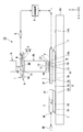
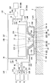
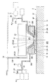
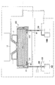
- FIG. 7 is a diagram illustrating an example of the liquid system 100 according to the present embodiment. 7 to 13 referred to in the following description, for ease of explanation, a part of the liquid immersion member 7 is shown in a sectional view parallel to the YZ plane, and a part thereof is a sectional view parallel to the XZ plane. It shows with. Specifically, in FIGS. 7 to 13, the left side with respect to the broken line is a cross-sectional view parallel to the YZ plane, and the right side with respect to the broken line is a cross-sectional view parallel to the XZ plane. That is, the liquid immersion member 7 shown in FIGS. 7 to 13 corresponds to a cross-sectional view taken along line AA in FIG. 7 to 13, the first supply port 21 is shown on the left side with respect to the broken line, and the second supply port 22 is shown on the right side with respect to the broken line.
- the liquid system 100 can supply the exposure liquid LQ.
- the first supply port 21 can supply the exposure liquid LQ from the liquid system 100 to the space SP1.
- the liquid system 100 can supply the cleaning liquid LC.
- the second supply port 22 can supply the cleaning liquid LC from the liquid system 100 to the space SP1.
- the liquid system 100 can recover the exposure liquid LQ recovered from the recovery port 20.
- the exposure liquid LQ recovered from the recovery port 20 in the exposure of the substrate P is sent to the liquid system 100.
- the recovery port 20 can recover the cleaning liquid LC.
- the cleaning liquid LC recovered from the recovery port 20 is sent to the liquid system 100.
- the liquid system 100 can supply the exposure liquid LQ to the first internal flow path 21 ⁇ / b> R of the liquid immersion member 7.
- the exposure liquid LQ supplied to the first internal channel 21R is sent to the first supply port 21 via the first internal channel 21R.
- the first supply port 21 supplies the exposure liquid LQ from the first internal flow path 21R to the space SP1.
- the liquid system 100 can supply the cleaning liquid LC to the second internal flow path 22R of the liquid immersion member 7.
- the cleaning liquid LC supplied to the second internal channel 22R is sent to the second supply port 22 through the second internal channel 22R.
- the second supply port 22 supplies the cleaning liquid LC from the second internal flow path 22R to the space SP1.
- the liquid recovered from the recovery port 20 (at least one of the exposure liquid LQ and the cleaning liquid LC) flows into the third internal flow path 20R of the liquid immersion member 7.
- the liquid system 100 recovers the liquid recovered from the recovery port 20 via the third internal flow path 20R.
- the device manufacturing system SYS includes the liquid system 100.
- the liquid system 100 is an external device (an apparatus different from the exposure apparatus EX) for the exposure apparatus EX.
- the exposure apparatus EX may include a part of the liquid system 100 or the entire liquid system 100.
- the liquid system 100 may supply liquid to the plurality of exposure apparatuses EX, and may recover liquid from the plurality of exposure apparatuses EX. It doesn't matter.
- the liquid system 100 includes a first flow path forming member 23T having a first flow path 23R through which the exposure liquid LQ supplied to the first supply port 21 flows, and a cleaning supplied to the second supply port 22.
- the second flow path forming member 24T having the second flow path 24R through which the liquid LC flows, and the third flow path 25R having the third flow path 25R through which the liquid (at least one of the exposure liquid LQ and the cleaning liquid LC) recovered from the recovery port 20 flows.
- 3 flow path forming member 25T is a tube member.
- one end of the first flow path 23R is connected to the first internal flow path 21R.
- One end of the second flow path 24R is connected to the second internal flow path 22R.
- One end of the third flow path 25R is connected to the third internal flow path 20R.
- the exposure liquid LQ flowing through the first flow path 23R is sent to the first supply port 21 via the first internal flow path 21R.
- the cleaning liquid LC flowing through the second flow path 24R is sent to the second supply port 22 via the second internal flow path 22R.
- the liquid recovered from the recovery port 20 and flowing through the third internal channel 20R is sent to the third channel 25R.
- the liquid system 100 includes a first discharge port 31 that discharges the liquid collected from the collection port 20, a second discharge port 32 that is different from the first discharge port 31, and the first and second discharge ports 31. , 32 and a third discharge port 33.
- the liquid recovered from the recovery port 20 and sent to the third flow path 25R via the third internal flow path 20R flows through the third flow path 25R, then the first discharge port 31, It is sent to at least one of the second discharge port 32 and the third discharge port 33.
- the liquid system 100 includes the first discharge port 31, the second discharge port 32, and the third discharge port 33.
- the exposure apparatus EX includes the first discharge port 31, the first discharge port 31, and the third discharge port 33. You may have at least 1 of the 2 discharge port 32 and the 3rd discharge port 33.
- FIG. In other words, at least one of the first discharge port 31, the second discharge port 32, and the third discharge port 33 may be a component of the exposure apparatus EX or a component of an external device with respect to the exposure apparatus EX.
- one end of the third flow path 25R is connected to the third internal flow path 20R, and the other end is connected to the flow path switching mechanism 30 including a valve mechanism.
- the liquid system 100 includes flow path forming members 31T, 32T, and 33T connected to the flow path switching mechanism 30.
- the flow path forming member 31T has a first discharge flow path 31R.
- the flow path forming member 32T has a second discharge flow path 32R.
- the flow path forming member 33T has a third discharge flow path 33R.
- One end of each of the first, second, and third discharge flow paths 31R, 32R, and 33R is connected to the flow path switching mechanism 30.
- the first discharge port 31 is disposed at the other end of the first discharge channel 31R.
- the second discharge port 32 is disposed at the other end of the second discharge channel 32R.
- the third discharge port 33 is disposed at the other end of the third discharge channel 33R.
- the flow path switching mechanism 30 collects liquid from the recovery port 20 and flows through the third flow path 25R into the first discharge flow path 31R (first discharge port 31) and the second discharge flow path 32R (second discharge port 32). ) And the third discharge flow path 33R (the third discharge port 33) so that the flow path is switched.
- the flow path switching mechanism 30 allows the flow path to be not supplied to the second and third discharge ports 32 and 33 when supplying the liquid from the third flow path 25R to the first discharge port 31. It can be adjusted. Further, the flow path switching mechanism 30 can adjust the flow path so that the liquid from the third flow path 25R is not supplied to the first and third discharge ports 31 and 33 when the liquid is supplied to the second discharge port 32. is there. Further, the flow path switching mechanism 30 can adjust the flow path so that the liquid from the third flow path 25R is not supplied to the first and second discharge ports 31 and 32 when supplied to the third discharge port 33. is there.
- the liquid system 100 includes a first storage member 41 that can store liquid discharged from the first discharge port 31 and a second storage member 42 that can store liquid discharged from the second discharge port 32. And a third storage member 43 that can store the liquid discharged from the third discharge port 33.
- each of the first, second, and third accommodation members 41, 42, and 43 is a tank.
- the other end of the first flow path 23 is connected to a supply source LQS that can supply the exposure liquid LQ.
- the supply source LQS may be included in the liquid system 100, or may be equipment of a factory FA where the exposure apparatus EX (device manufacturing system SYS) is installed. Further, the exposure apparatus EX may include a supply source LQS.
- a flow path switching mechanism 34 including a valve mechanism is disposed in a part of the first flow path 23R.
- the flow path switching mechanism 34 is connected to one end of the fourth flow path 26R formed by the fourth flow path forming member 26T.
- the exposure liquid LQ supplied from the supply source LQS flows through at least one of the first flow path 23R and the fourth flow path 26R.
- the flow path switching mechanism 34 switches the flow path so that the exposure liquid LQ flowing through the first flow path 23R is sent to at least one of the first supply port 21 (first flow path 23R) and the fourth flow path 26R. .
- the flow path switching mechanism 34 supplies the exposure liquid LQ from the supply source LQS to the first supply port 21 (first flow path 23R)
- the exposure liquid LQ is not supplied to the fourth flow path 26R.
- the flow path can be adjusted.
- the flow path switching mechanism 34 supplies the exposure liquid LQ from the supply source LQS to the fourth flow path 26R, the exposure liquid LQ is not supplied to the first supply port 21 (first flow path 23R).
- the flow path can be adjusted.
- the liquid system 100 includes a dilution device 35.
- the other end of the fourth flow path 26R is connected to the dilution device 35.
- the liquid system 100 includes the cleaning liquid supply device 36 that can supply the cleaning liquid LC.
- the first cleaning liquid LC1 and the second cleaning liquid LC2 are used as the cleaning liquid LC.
- the liquid system 100 includes a first cleaning liquid supply device 36A that can supply the first cleaning liquid LC1 and a second cleaning liquid supply device 36B that can supply the second cleaning liquid LC2.
- the other end of the second flow path 24R is connected to the first cleaning liquid supply device 36A.
- a flow path switching mechanism 38 including a valve mechanism is disposed in a part of the second flow path 24R.
- the flow path switching mechanism 38 is connected to one end of the fifth flow path 27R formed by the fifth flow path forming member 27T.
- the other end of the fifth flow path 27R is connected to the diluting device 35.
- the diluting device 35 and the second cleaning liquid supply device 36B are connected via the sixth flow path 28R formed by the sixth flow path forming member 28T.
- the second cleaning liquid supply device 36B can supply the second cleaning liquid LC2 to the dilution device 35 through the sixth flow path 28R. Further, the exposure liquid LQ flowing through the fourth flow path 26R is sent to the dilution device 35.
- the diluting device 35 dilutes the second cleaning liquid LC2 with the exposure liquid LQ.
- the second cleaning liquid LC2 diluted with the dilution device 35 and supplied from the dilution device 35 flows through the fifth flow path 27R.
- the second cleaning liquid LQ2 flowing through the fifth flow path 27R is sent to the flow path switching mechanism 38.
- the flow path switching mechanism 38 At least one of the first cleaning liquid LC1 from the first cleaning liquid supply device 36A and the second cleaning liquid LC2 from the second cleaning liquid supply device 36B (dilution device 35) flows in the second flow.
- the flow path is switched so as to be sent to the second supply port 22 via the path 24R.
- the flow path switching mechanism 38 when the flow path switching mechanism 38 supplies the first cleaning liquid LC1 from the first cleaning liquid supply device 36A to the second supply port 22, the second cleaning liquid LC2 is supplied to the second supply port 22.
- the flow path can be adjusted so that it is not.
- the flow path switching mechanism 38 supplies the second cleaning liquid LC2 from the second cleaning liquid supply device 36B (dilution device 35) to the second supply port 22, the first cleaning liquid LC1 is supplied to the second supply port 22. It is possible to adjust the flow path so that it is not supplied to.
- the fifth flow path 27R can be connected to at least one of the first housing member 41, the second housing member 42, and the third housing member 43.
- a flow path switching mechanism 39 including a valve mechanism is disposed in a part of the fifth flow path 27R.
- the liquid system 100 includes a detection device 40 that detects characteristics (for example, at least one of properties and components) of the liquid recovered from the recovery port 20.
- the detection device 40 measures the liquid recovered from the recovery port 20 and flowing through the third flow path 25R.
- the characteristics of the liquid include the conductivity of the liquid.
- the detection device 40 includes a conductivity meter. The detection device 40 detects the conductivity of the liquid. The detection result of the detection device 40 may be output to the control device 8, for example. The control device 8 can determine the characteristics of the liquid based on the detection result of the detection device 40. Note that the detection result of the detection device 40 may be output to the main controller MC, and the main controller MC may obtain the characteristics of the liquid. The characteristics of the liquid that has passed through the flow path switching mechanism 38 may be detected.
- a detection device may be provided in each of the first, second, and third discharge flow paths 31R, 32R, and 33R, or a part of the first, second, and third discharge flow paths 31R, 32R, and 33R.
- a detection device may be provided.
- the detection device 40 may be used together, or the detection device 40 may be omitted.
- the liquid system 100 includes a suction device 45 including a vacuum system that reduces the pressure of the third internal flow path 20R.
- the suction device 45 is connected to the third flow path 25R, for example.
- the suction device 45 reduces the pressure of the third flow path 25R and the third internal flow path 20R connected to the third flow path 35R, and the pressure of the space SP2 that the lower surface 19B faces and the space that the upper surface 19A faces.
- the pressure of the (third internal flow path 20R) to be different (generating a differential pressure)
- the liquid existing in the space SP2 can be recovered from the recovery port 20 (the hole 19H of the porous member 19). it can.
- the liquid recovered from the recovery port 20 is discharged from at least one of the first discharge port 31, the second discharge port 32, and the third discharge port 33.
- the liquid flowing into the third flow path 25R from the recovery port 20 is discharged from at least one of the first discharge port 31, the second discharge port 32, and the third discharge port 33 using gravity.
- at least one of the first accommodation member 41, the second accommodation member 42, and the third accommodation member 43 is connected to the vacuum system to accommodate (suction) the liquid flowing into the third flow path 25R from the recovery port 20. May be.
- the control device 8 moves the substrate stage 2 to the substrate exchange position in order to load (load) the substrate P before exposure onto the substrate stage 2.
- the substrate replacement position is a position away from the liquid immersion member 7 (projection region PR) and a position where the substrate P replacement process can be performed.
- the substrate P replacement process is a process of carrying out (unloading) the exposed substrate P held on the substrate stage 2 (substrate holding unit 11) from the substrate stage 2 using a predetermined transfer device (not shown). And at least one of processing for loading (loading) the substrate P before exposure into the substrate stage 2 (substrate holding unit 11).
- the control device 8 moves the substrate stage 2 to the substrate replacement position and executes the substrate P replacement process.
- the control device 8 arranges the measurement stage 3 at a position facing the terminal optical element 12 and the liquid immersion member 7, and the terminal optical element 12.
- the exposure liquid LQ is held between the liquid immersion member 7 and the measurement stage 3 to form the liquid immersion space LS.
- measurement processing using the measurement stage 3 may be performed as necessary in at least a part of the period in which the substrate stage 2 is separated from the liquid immersion member 7.
- the control device 8 makes the terminal optical element 12 and the liquid immersion member 7 and the measurement stage 3 face each other, and the exposure light EL between the terminal optical element 12 and the measurement member C is used.
- the immersion space LS is formed so that the optical path K is filled with the exposure liquid LQ.
- the control device 8 irradiates the measurement member C (measurement device) held on the measurement stage 3 with the exposure light EL via the projection optical system PL and the exposure liquid LQ, and executes the measurement process of the exposure light EL. .
- the result of the measurement process may be reflected in the exposure process of the substrate P executed thereafter. Note that the measurement process need not be executed.
- control device 8 moves the substrate stage 2 to the projection region PR, and the last optical element 12 and the liquid immersion member.
- An immersion space LS is formed between 7 and the substrate stage 2 (substrate P).
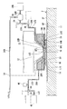
- FIG. 8 is a view showing a state in which the immersion space LS is formed with the exposure liquid LQ between the terminal optical element 12 and the liquid immersion member 7 and the substrate P.
- the exposure liquid LQ supplied from the supply source LQS is supplied to the first supply port 21 via the first flow path 23R and the first internal flow path 21R.
- the first supply port 21 supplies the exposure liquid LQ to the space SP1 (optical path K).
- the exposure liquid LQ supplied to the space SP1 flows into the space SP2 through the opening 7K.
- the operation of recovering the exposure liquid LQ from the recovery port 20 is executed. Thereby, an immersion space LS is formed with the exposure liquid LQ between the last optical element 12 and the immersion member 7 and the substrate P (substrate stage 2).
- the collection port 20 collects the exposure liquid LQ in the space SP2.
- the exposure liquid LQ recovered from the recovery port 20 flows through the third internal channel 20R and the third channel 25R.
- the flow path is adjusted by the flow path switching mechanism 30 so that the exposure liquid LQ recovered from the recovery port 20 is discharged from the first discharge port 31.
- the exposure liquid LQ discharged from the first discharge port 31 is supplied to the first storage member 41.
- the control device 8 After the immersion space LS is formed between the last optical element 12 and the liquid immersion member 7 and the substrate stage 2 (substrate P), the control device 8 starts the exposure processing of the substrate P.
- the terminal optical element 12 and the liquid immersion member 7 are opposed to the substrate P, and the optical path K of the exposure light EL between the terminal optical element 12 and the substrate P is filled with the exposure liquid LQ.
- the immersion space LS is formed as described above.
- the illumination system IL illuminates the mask M with the exposure light EL.
- the exposure light EL from the mask M is applied to the substrate P through the projection optical system PL and the exposure liquid LQ supplied from the first supply port 21. Thereby, the substrate P is exposed with the exposure light EL emitted from the last optical element 12.
- the pattern image of the mask M is projected onto the substrate P.
- the exposure apparatus EX of the present embodiment is a scanning exposure apparatus (so-called scanning stepper) that projects an image of the pattern of the mask M onto the substrate P while moving the mask M and the substrate P synchronously in a predetermined scanning direction.
- the scanning direction (synchronous movement direction) of the substrate P is the Y-axis direction
- the scanning direction (synchronous movement direction) of the mask M is also the Y-axis direction.
- the control device 8 moves the substrate P in the Y axis direction with respect to the projection region PR of the projection optical system PL, and in the illumination region IR of the illumination system IL in synchronization with the movement of the substrate P in the Y axis direction.
- the substrate P is irradiated with the exposure light EL through the projection optical system PL and the exposure liquid LQ in the immersion space LS on the substrate P while moving the mask M in the Y-axis direction.
- the control device 8 moves the substrate stage 2 to the substrate replacement position.
- the measurement stage 3 is disposed so as to face the last optical element 12 and the liquid immersion member 7, for example.
- the exposed substrate P is unloaded from the substrate stage 2 moved to the substrate exchange position, and the unexposed substrate P is loaded into the substrate stage 2.
- control device 8 repeats the above process to sequentially expose the plurality of substrates P.
- the terminal optical element 12 and the liquid immersion member 7 are used in at least a part of the exposure sequence including the replacement process of the substrate P, the measurement process using the measurement stage 3, and the exposure process of the substrate P.
- the exposure liquid LQ is supplied from the first supply port 21 between the terminal optical element 12 and the object (at least one of the substrate P, the substrate stage 2 and the measurement stage 3) disposed opposite to the liquid immersion member 7.
- at least a part of the exposure liquid LQ supplied from the first supply port 21 is recovered from the recovery port 20.
- the exposure liquid LQ recovered from the recovery port 20 in the exposure sequence is discharged from the first discharge port 31.
- the cleaning liquid LC is not supplied from the cleaning liquid supply device 36 during the exposure sequence. That is, the liquid supply from the second supply port 22 is stopped during the exposure sequence. In the exposure sequence, the supply of the exposure liquid LQ from the first supply port 21 is executed, and the liquid supply from the second supply port 22 is stopped.
- the exposure liquid LQ in the immersion space LS is the terminal optical element during at least a part of the exposure sequence including the replacement process of the substrate P, the measurement process using the measurement stage 3, and the exposure process of the substrate P. 12, contact with at least a part of the liquid immersion member 7, the substrate stage 2, and the measurement stage 3.
- the liquid immersion space LS is improved. There is a possibility that it cannot be formed. As a result, exposure failure may occur.
- the control device 8 is in contact with the exposure liquid LQ in the immersion space LS at a predetermined timing in the exposure sequence period and / or in a period other than the exposure sequence.
- a liquid member cleaning process is executed.
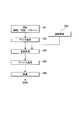
- FIG. 14 is a flowchart illustrating an example of a cleaning sequence according to the present embodiment.
- the cleaning sequence according to the present embodiment includes a process of carrying the dummy substrate DP into the substrate stage 2 (step SA1) and a process of supplying the first cleaning liquid LC1 to the liquid immersion member 7 and cleaning the liquid immersion member 7 (Step SA2), a process of supplying the rinsing liquid LH to the liquid immersion member 7 (Step SA3), and a process of supplying the second cleaning liquid LC2 to the liquid immersion member 7 and cleaning the liquid immersion member 7 (Step SA4).
- step SA5 the process of supplying the rinse liquid LH to the liquid immersion member 7
- step SA6 the process of supplying the rinse liquid LH to the liquid immersion member 7
- step SA7 Processing
- the cleaning process (SA2) using the first cleaning liquid LC1 is appropriately referred to as a first cleaning process
- the cleaning process (SA4) using the second cleaning liquid LC2 is appropriately referred to as a second cleaning process.
- the process of supplying the rinsing liquid LH to a member such as the liquid immersion member 7 cleaned using the cleaning liquid LC (LC1, LC2) is appropriately referred to as a rinsing process.
- the rinsing process includes a process of supplying the rinsing liquid LH to the member, rinsing the member, and removing the cleaning liquid LC (LC1, LC2) remaining on the member.
- the rinsing process (SA3) executed after the first cleaning process is appropriately referred to as a first rinsing process
- the rinsing process (SA5) executed after the second cleaning process is appropriately set as the second rinsing process.
- the rinse process (SA6) executed after the second rinse process is appropriately referred to as a third rinse process.
- An alkaline liquid may be used as the first cleaning liquid LC1. That is, an alkaline solution containing a predetermined substance may be used as the first cleaning liquid LC1.
- the first cleaning liquid LC1 may include tetramethylammonium hydroxide (TMAH) as a predetermined substance.
- TMAH tetramethylammonium hydroxide
- an alkaline aqueous solution may be used as the first cleaning liquid LC1.
- An acidic liquid may be used as the second cleaning liquid LC2. That is, an acidic solution containing a predetermined substance may be used as the second cleaning liquid LC2.
- the second cleaning liquid LC2 may include hydrogen peroxide as the predetermined substance.
- an acidic aqueous solution may be used as the second cleaning liquid LC2.
- first cleaning liquid LC1 and the rinsing liquid LH may include the same type of liquid.
- second cleaning liquid LC2 and the rinse liquid LH may include the same type of liquid.
- an alkaline aqueous solution is used as the first cleaning liquid LC1.
- An aqueous hydrogen peroxide solution is used as the second cleaning liquid LC2.
- An exposure liquid LQ is used as the rinse liquid LH. That is, in the present embodiment, the rinse liquid LH is water (pure water).
- each of the first cleaning liquid LC1, the second cleaning liquid LC2, and the rinse liquid LH contains water as the same type of liquid.
- a tetramethyl ammonium hydroxide (TMAH) aqueous solution is used as the first cleaning liquid LC1.
- TMAH tetramethyl ammonium hydroxide
- a hydrogen peroxide aqueous solution hydrogen peroxide solution
- LC2 hydrogen peroxide solution
- the alkaline solution used as the first cleaning liquid LC1 is not limited to tetramethylammonium hydroxide, but also an inorganic alkali solution such as sodium hydroxide and potassium hydroxide, and an organic alkali such as trimethyl (2-hydroxyethyl) ammonium hydroxide.
- an inorganic alkali solution such as sodium hydroxide and potassium hydroxide
- an organic alkali such as trimethyl (2-hydroxyethyl) ammonium hydroxide.
- ammonia water may be used as the first cleaning liquid LC1.
- the second cleaning liquid LC2 may contain a buffered hydrofluoric acid solution. Further, the second cleaning liquid LC2 may be a solution containing buffered hydrofluoric acid and hydrogen peroxide.
- Buffered hydrofluoric acid (buffered hydrofluoric acid) is a mixture of hydrofluoric acid and ammonium fluoride.
- the mixing ratio may be 5 to 2000 in terms of a volume ratio of 40 wt% ammonium fluoride solution / 50 wt% hydrofluoric acid.
- the mixing ratio of buffered hydrofluoric acid and hydrogen peroxide may be 0.8 to 55 in terms of the hydrogen peroxide / hydrofluoric acid weight ratio.
- An ozone liquid containing ozone may be used as the second cleaning liquid LC2.
- a solution containing hydrogen peroxide and ozone may be used.
- At least one of the first cleaning liquid LC1 and the second cleaning liquid LC2 may contain alcohol.
- at least one of the first cleaning liquid LC1 and the second cleaning liquid LC2 may include at least one of ethanol, isopropyl alcohol (IPA), and pentanol.
- each of the first cleaning liquid LC1 and the second cleaning liquid LC2 may be alcohol, for example.
- the dummy substrate DP is disposed at a position facing the liquid immersion member 7 in at least a part of the cleaning sequence of the liquid immersion member 7.
- a device pattern cannot be formed on the dummy substrate DP. That is, the photosensitive film is not formed on the dummy substrate DP.
- the dummy substrate DP is a substrate that is less likely to emit foreign matter than the substrate P. Further, the dummy substrate DP may have a function of collecting foreign matter on the surface of the dummy substrate DP. In this case, it is desirable that the dummy substrate DP is difficult to release foreign matter collected (attached) on the surface of the dummy substrate DP.
- the outer shape and size of the dummy substrate DP are substantially the same as the outer shape and size of the substrate P.
- the substrate holding part 11 can hold the dummy substrate DP.
- at least a part of the cleaning sequence of the liquid immersion member 7 is executed in a state where the dummy substrate DP held by the substrate stage 2 (substrate holding unit 11) and the liquid immersion member 7 face each other. . That is, the first cleaning liquid LC1, the second cleaning liquid LC2, and the rinsing liquid LH are supplied in a state where the dummy substrate DP is disposed so as to face the liquid immersion member 7, respectively.
- At least one of the outer shape and size of the dummy substrate DP may be different from that of the substrate P.
- the size of the dummy substrate may be smaller than the substrate P.
- the dummy substrate DP may not be held by the substrate holder 11 in at least a part of the cleaning sequence of the liquid immersion member 7.
- the dummy substrate DP is released from the substrate holding unit 11 and the dummy substrate DP is supported by a support mechanism different from the substrate holding unit 11 so that the liquid immersion member 7 and the dummy substrate DP are kept facing each other. May be.
- the substrate holding unit 11 substrate stage 2 may be separated from the bottom of the liquid immersion member 7.
- At least one of the first cleaning liquid LC1, the second cleaning liquid LC2, and the rinsing liquid LH is disposed so as to face the liquid immersion member 7, and at least one of the upper surface 2F of the substrate stage 2 and the upper surface 3F of the measurement stage 3 is disposed. Or may be supplied in a state where an object other than the dummy substrate DP, the substrate stage 2 and the measurement stage 3 is arranged.
- the liquid comes into contact with at least a part of the surface of the dummy substrate DP.
- the surface of the dummy substrate DP is liquid repellent with respect to the rinsing liquid LH. In the present embodiment, the surface of the dummy substrate DP is also liquid repellent with respect to the first and second cleaning liquids LC1 and LC2.
- the dummy substrate DP includes a base material including a semiconductor wafer such as a silicon wafer, and a liquid repellent film formed on the base material. At least a part of the surface of the dummy substrate DP includes the liquid repellent film.
- a liquid repellent film that forms at least a part of the surface of the dummy substrate DP is appropriately referred to as a liquid repellent film.
- the liquid repellent film may be formed of a material containing fluorine.
- the liquid repellent film may be formed of a resin containing fluorine.
- the liquid repellent film may be formed of polytetrafluoroethylene (PFA), polytetrafluoroethylene (PTFE), Teflon (registered trademark), or the like.
- the liquid repellent film may be a silicon carbonitride (SiCN) film formed by, for example, a CVD method.
- the liquid repellent film is not limited to a resin containing fluorine.
- the liquid repellent film is resistant to the first and second cleaning liquids LC1 and LC2 and the rinsing liquid LH, and a surface on which the liquid immersion space can be satisfactorily formed with the liquid immersion member 7. What is necessary is just to have (liquid repellency).
- the contact angle of the first liquid LC1 and the contact angle of the second liquid LC2 on the surface of the dummy substrate DP are 80 degrees or more, 90 degrees or more, 100 degrees or more, 110 or more, or 120 degrees or more. is there.
- another film for example, a film that improves the adhesion between the base material and the liquid repellent film may be formed between the base material and the liquid repellent film.
- the control device 8 executes a process of loading (loading) the dummy substrate DP into the substrate stage 2 (step SA1). In order to carry the dummy substrate DP into the substrate stage 2 (substrate holding unit 11), the control device 8 moves the substrate stage 2 to the substrate replacement position. When the substrate P is held by the substrate holding unit 11, the process of carrying out the dummy substrate DP into the substrate holding unit 11 is executed after the process of carrying out the substrate P from the substrate stage 2 is executed.
- the control device 8 sets the substrate so that the dummy substrate DP held by the substrate stage 2 is disposed at a position facing the terminal optical element 12 and the liquid immersion member 7. Move stage 2.
- the control device 8 starts the first cleaning process (step SA2).
- step SA2 After all the exposure liquid LQ in the immersion space LS between the last optical element 12 and the liquid immersion member 7 and the object (substrate stage 2, measurement stage 3, dummy substrate DP, etc.) is collected. The first cleaning process is started.
- the measurement stage 3 is disposed at a position facing the terminal optical element 12 and the liquid immersion member 7 in a state where the substrate stage 2 is disposed at the substrate replacement position for carrying in the dummy substrate DP. .
- the control device 8 exposes the exposure liquid from the first supply port 21. With the supply of LQ stopped, the exposure liquid LQ is recovered from the recovery port 20 (the hole 19H of the porous member 19) for a predetermined time. Thereby, substantially all the exposure liquid LQ between the last optical element 12 and the liquid immersion member 7 and the measurement stage 3 is collected.
- an object different from the measurement stage 3 may be disposed at a position facing the terminal optical element 12 and the liquid immersion member 7.
- the first supply port 21 The supply of the exposure liquid LQ may be stopped, and the recovery of the exposure liquid LQ from the recovery port 20 may be executed for a predetermined time.
- the exposure liquid LQ may be collected from the second supply port 22 as well as the collection operation from the collection port 20. That is, the second supply port 22 may function as a collection port for the exposure liquid LQ.
- the exposure liquid LQ can be recovered from the second supply port 22 by connecting the second supply port 22 to the vacuum system.
- the collection operation from the second supply port 22 may be performed, and the collection operation from the collection port 20 may not be performed. Further, the exposure liquid LQ may be recovered from the first supply port 21 by connecting the first supply port 21 to a vacuum system.
- the exposure liquid LQ remaining in the first internal flow path 21R may be removed when the first cleaning process is executed.
- the first internal flow path 21R and the first flow path 23R is depressurized, and exposure remains in at least one of the first internal flow path 21R and the first flow path 23R.
- the liquid LQ may be removed.
- a vacuum system a suction device
- the first internal channel 21R is aspirated (decompressed).
- the exposure liquid LQ remaining in the first internal channel 21R is sucked into the vacuum system, and the exposure liquid LQ is discharged from the first internal channel 21R.
- at least one of the first internal flow path 21R and the first flow path 23R may be pressurized to remove the exposure liquid LQ remaining in at least one of the first internal flow path 21R and the first flow path 23R.
- a gas supply device is connected to at least one of the first internal channel 21R and the first channel 23R, and gas is supplied to the first internal channel 21R.
- the first internal channel 21R may be pressurized.
- the exposure liquid LQ remaining in the first internal flow path 21R is discharged from the first supply port 21, and the exposure liquid LQ is discharged from the first internal flow path 21R.
- the first internal flow path 21R and the first cleaning liquid supply device 36A are connected by a predetermined flow path, and the first cleaning liquid LC1 sent from the first cleaning liquid supply device 36A is connected to the first internal flow path.
- 21R may be supplied and the exposure liquid LQ may be discharged from the first internal channel 21R.
- the cleaning process may be started while the exposure liquid LQ remains in at least one of the first internal channel 21R and the first channel 23R.
- the controller 8 starts the first cleaning process in a state where all the exposure liquid LQ is collected and the last optical element 12 and the liquid immersion member 7 face the dummy substrate DP.
- the control device 8 starts supplying the first cleaning liquid LC1 in order to clean the liquid immersion member 7 with the first cleaning liquid LC1.
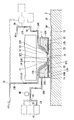
- FIG. 9 is a diagram illustrating an example of a state in which the first cleaning process is being performed.
- the control device 8 starts supplying the first cleaning liquid LC1 from the second supply port 22.
- the control device 8 supplies the first cleaning liquid LC1 from the second supply port 22 to the space SP1 with the supply of the exposure liquid LQ from the first supply port 21 stopped.
- the recovery of the first cleaning liquid LC1 from the recovery port 20 is executed in parallel with the supply of the first cleaning liquid LC1 from the second supply port 22.
- the immersion space LT1 is formed by the first cleaning liquid LC1 between the last optical element 12 and the liquid immersion member 7 and the dummy substrate DP.
- the first cleaning liquid LC1 is delivered from the first cleaning liquid supply device 36A.
- the first cleaning liquid supply device 36A may be a facility of the factory FA.
- the first cleaning liquid LC1 supplied from the first cleaning liquid supply device 36A is supplied to the second supply port 22 via the second flow path 24R and the second internal flow path 22R.
- the second supply port 22 supplies the first cleaning liquid LC1 to the space SP1.
- the first cleaning liquid LC1 supplied to the space SP1 flows into the space SP2 through the opening 7K.
- the first cleaning liquid LC1 contacts at least a part of the surface of the liquid immersion member 7 including the lower surface 14.
- the surface of the liquid immersion member 7 is cleaned with the first cleaning liquid LC1.
- the first cleaning liquid LC1 contains an alkali and can remove foreign matters including organic substances present on the surface (the lower surface 14 and the like) of the liquid immersion member 7. Therefore, by supplying the first cleaning liquid LC1 so as to come into contact with the liquid immersion member 7, the foreign matter adhering to the liquid immersion member 7 is removed.
- the recovery port 20 recovers the first cleaning liquid LC1 supplied from the second supply port 22 to at least a part of the surface of the liquid immersion member 7.
- the recovery port 20 recovers the first cleaning liquid LC1 in the space SP2.
- the foreign matter removed from the surface of the liquid immersion member 7 is recovered from the recovery port 20 together with the first cleaning liquid LC1.
- the first cleaning liquid LC1 recovered from the recovery port 20 flows through the third internal channel 20R and the third channel 25R.
- the flow path switching mechanism 30 adjusts the flow path so that the first cleaning liquid LC1 recovered from the recovery opening 20 is discharged from the second discharge opening 32.
- the first cleaning liquid LC1 supplied to the liquid immersion member 7 and recovered from the recovery port 20 is discharged from the second discharge port 32.
- the first cleaning liquid LC1 discharged from the second discharge port 32 is supplied to the second storage member 42.
- the immersion space LT1 is formed by the first cleaning liquid LC1.
- the 1st cleaning liquid LC1 is diluted with the exposure liquid LQ between the last optical element 12 and the liquid immersion member 7, and the dummy substrate DP.
- the concentration of alkali contained in the first cleaning liquid LC1 sent from the first cleaning liquid supply device 36A and supplied from the second supply port 22 to the surface of the liquid immersion member (liquid contact member) 7 is a concentration suitable for cleaning. Has been adjusted.
- the first cleaning liquid LC1 By suppressing the first cleaning liquid LC1 from being diluted with the exposure liquid LQ between the last optical element 12 and the liquid immersion member 7 and the dummy substrate DP, the first cleaning liquid containing an alkali having a concentration suitable for cleaning.
- the liquid immersion member 7 can be cleaned with LC1.
- the supply of the exposure liquid LQ from the first supply port 21 is stopped in the first cleaning process.
- the exposure liquid LQ may be filled in the first internal channel 21R.
- the first cleaning liquid LC1 becomes the first internal flow path 21R, the first flow path Intrusion into 23R and the like can be suppressed.
- the first cleaning liquid LC1 may enter the first internal channel 21R from the first supply port 21.
- step SA2 After supplying the first cleaning liquid LC1 from the second supply port 22 for a predetermined time, the control device 8 stops supplying the first cleaning liquid LC1 from the second supply port 22. Thereby, the first cleaning process (step SA2) is completed.
- the first rinse process is started (step SA3).
- the first rinsing process is started after all of the first cleaning liquid LC1 in the immersion space LT1 has been collected.
- the control device 8 executes the recovery of the first cleaning liquid LC1 from the recovery port 20 (the hole 19H of the porous member 19) for a predetermined time while the supply of the first cleaning liquid LC1 from the second supply port 22 is stopped. . Thereby, almost all the first cleaning liquid LC1 between the last optical element 12 and the liquid immersion member 7 and the dummy substrate DP is recovered.
- the first cleaning liquid LC1 in order to collect all the first cleaning liquid LC1, not only the recovery operation from the recovery port 20, but also the first cleaning liquid LC1 may be recovered from the second supply port 22.
- the first cleaning liquid LC1 can be recovered from the second supply port 22 by connecting the second supply port 22 to the vacuum system.
- the collecting operation from the second supply port 22 may be executed and the collecting operation from the collecting port 20 may not be executed.
- the first supply port 21 may be connected to a vacuum system, and the first cleaning liquid LC1 may be recovered from the first supply port 21.
- the first cleaning liquid LC1 remaining in the second internal flow path 22R may be removed when performing the first rinsing process.
- the first cleaning liquid LC1 may be removed.
- a vacuum system a suction device
- the second internal flow path 22R is sucked (depressurized).
- the first cleaning liquid LC1 remaining in the second internal flow path 22R is sucked into the vacuum system, and the first cleaning liquid LC1 is discharged from the second internal flow path 22R.
- at least one of the second internal flow path 22R and the second flow path 24R may be pressurized to remove the first cleaning liquid LC1 remaining in at least one of the second internal flow path 22R and the second flow path 24R.
- a gas supply device is connected to at least one of the second internal flow path 22R and the second flow path 24R, and gas is supplied to the second internal flow path 22R.
- the second internal flow path 22R may be pressurized.
- the first cleaning liquid LC1 remaining in the second internal flow path 22R is discharged from the second supply port 22, and the first cleaning liquid LC1 is discharged from the second internal flow path 22R.
- the second internal flow path 22R and the supply source LQS are connected by a predetermined flow path, and the exposure liquid LQ sent from the supply source LQS is supplied to the second internal flow path 22R, and the second internal flow path 22R is supplied.
- the first cleaning liquid LC1 may be discharged from the flow path 22R.
- the first cleaning liquid LC1 may be removed (discharged) from at least one of the fifth flow path 27R and the second flow path 24R.
- the exposure liquid LQ sent from the supply source LQS may be supplied to at least one of the fifth flow path 27R and the second flow path 24R.
- FIG. 10 is a diagram illustrating an example of a state in which the first rinse process is being performed. Also in the first rinsing process, the dummy substrate DP is disposed facing the liquid immersion member 7.
- the control device 8 starts supplying the rinsing liquid LH in order to rinse the liquid immersion member 7 with the rinsing liquid LH.
- the supply of the rinsing liquid LH may be started in a state where the immersion space LT1 for the first cleaning liquid LC1 is formed.
- the control device 8 starts supplying the rinsing liquid LH from the first supply port 21.
- the control device 8 supplies the rinsing liquid LH from the first supply port 21 to the space SP1 in a state where the supply of the cleaning liquid LC from the second supply port 22 is stopped.
- the exposure liquid LQ is used as the rinse liquid LH.
- the liquid from the recovery port 20 (including at least one of the first cleaning liquid LC1 and the rinsing liquid LH). Recovery is performed. Thereby, the immersion space LSh is formed with the rinsing liquid LH between the last optical element 12 and the liquid immersion member 7 and the dummy substrate DP.
- the rinsing liquid LH (exposure liquid LQ) is sent from the supply source LQS.
- the rinse liquid LH supplied from the supply source LQS is supplied to the first supply port 21 via the first flow path 23R and the first internal flow path 21R.
- the first supply port 21 supplies the rinse liquid LH to the space SP1.
- the rinse liquid LH supplied to the space SP1 flows into the space SP2 through the opening 7K.
- the rinse liquid LH contacts at least a part of the surface of the liquid immersion member 7 including the lower surface 14.
- the surface of the liquid immersion member 7 is rinsed with the rinse liquid LH.
- the rinse liquid LH can remove the first cleaning liquid LC1 remaining on the surface of the liquid immersion member 7.
- the rinsing liquid LH supplied from the first supply port 21 comes into contact with the liquid immersion member 7, the first cleaning liquid LC1 remaining in the liquid immersion member 7 can be removed.
- the rinsing liquid LH is pure water
- the first cleaning liquid LC1 is an alkaline aqueous solution. Therefore, the rinsing liquid LH can remove the first cleaning liquid LC1 remaining in the liquid immersion member 7. Further, since the rinsing liquid LH supplied from the first supply port 21 comes into contact with the liquid immersion member 7, it is possible to remove foreign matters adhering to the liquid immersion member 7 by the rinsing liquid LH.
- the recovery port 20 recovers the rinse liquid LH supplied from the first supply port 21 to at least a part of the surface of the liquid immersion member 7.
- the recovery port 20 recovers the rinse liquid LH in the space SP2.
- the first cleaning liquid LC1 removed from the surface of the liquid immersion member 7 is recovered from the recovery port 20 together with the rinse liquid LH.
- the liquid is also collected from the second supply port 22 in the first rinsing process.
- the second supply port 22 can be connected to a vacuum system and can function as a liquid recovery port. That is, in the present embodiment, the recovery of the liquid from the recovery port 20 and the second supply port 22 is executed in parallel with the supply of the rinse liquid LH from the first supply port 21.
- the first cleaning liquid LC1 remaining in the second internal flow path 22R, the second flow path 24R, and the like is removed.
- the second internal flow path 22R, the second flow path 24R, and the like are rinsed with the rinsing liquid LH.
- the rinse liquid LH recovered from the recovery port 20 flows through the third internal channel 20R and the third channel 25R.
- the rinse liquid LH recovered from the second supply port 22 flows through the second internal channel 22R and the second channel 24R.
- the flow path is adjusted by the flow path switching mechanism 30 so that the rinse liquid LH recovered from the recovery port 20 is discharged from the second discharge port 32.
- the rinse liquid LH supplied to the liquid immersion member 7 and recovered from the recovery port 20 is discharged from the second discharge port 32.
- the rinse liquid LH discharged from the second discharge port 32 is supplied to the second storage member 42.
- the rinse liquid LH recovered from the recovery port 20 is discharged from the second discharge port 32.
- the rinse liquid LH recovered from the second supply port 22 is sent to the flow path switching mechanism 39 via the second internal flow path 22R, the second flow path 24R, and the fifth flow path 27R.
- the flow path switching mechanism 39 adjusts the flow path so that the rinse liquid LH recovered from the second supply port 22 is sent to the second storage member 42.
- the control device 8 executes the supply of the rinse liquid LH from the first supply port 21 and the recovery of the rinse liquid LH from the recovery port 20 and the second supply port 22 for a predetermined period.
- the rinsing liquid LH may be supplied from the first and second supply ports 21 and 22, and the supplied rinsing liquid LH may be recovered from the recovery port 20.
- the recovery from the second supply port 22 is stopped.
- the recovery from the recovery port 20 may be performed together with the supply of the rinse liquid LH from the first supply port 21.
- the recovery from the second supply port 22 may not be performed.
- the characteristics of the rinse liquid LH recovered from the recovery port 20 are detected by the detection device 40 in the first rinse process.
- the detection device 40 detects the characteristics of the rinsing liquid LH recovered from the recovery port 20 and flowing through the third flow path 25R.
- the detection device 40 detects the conductivity of the rinse liquid LH recovered from the recovery port 20.
- the detection result of the detection device 40 is output to the control device 8.
- the control device 8 obtains the concentration of alkali (tetramethylammonium hydroxide) contained in the rinse liquid LH recovered from the detection result of the detection device 40, and the first until the concentration falls below a predetermined allowable value.
- the rinsing process supply and recovery of the rinsing liquid LH
- the first rinsing process is continued until the concentration of alkali contained in the rinsing liquid LH recovered from the recovery port 20 becomes 1% or less.
- step SA3 After confirming that the concentration of alkali contained in the rinsing liquid LH recovered from the recovery port 20 is below the allowable value based on the detection result of the detection device 40, the first rinsing process (step SA3) ends. To do.
- Step SA4 the control device 8 starts the second cleaning process.
- the control device 8 starts supplying the second cleaning liquid LC2 in order to clean the liquid immersion member 7 with the second cleaning liquid LC2.
- the supply of the rinse liquid LH from the first supply port 21 and the recovery of the rinse liquid LH from the recovery port 20 until the supply of the second cleaning liquid LC2 to the liquid immersion member 7 is started.
- Parallel operations are executed. That is, after the supply of the rinsing liquid LH is stopped, the supply of the second cleaning liquid LC2 is started in a state where the immersion space LSh of the rinsing liquid LH is formed.
- the second cleaning process (second cleaning process) is performed after all the rinsing liquid LH in the immersion space LSh between the last optical element 12 and the liquid immersion member 7 and the dummy substrate DP is collected.
- Supply of liquid LC2) may be started.
- the rinse liquid LH remaining in the first internal flow path 21R may be removed when the second cleaning process is performed.
- the rinse liquid LH remaining in the first internal flow path 21R may be removed when the second cleaning process is performed.
- the rinse liquid LH remaining in the first internal flow path 21R may be removed.
- at least one of the first internal channel 21R and the first channel 23R is depressurized or pressurized and remains in at least one of the first internal channel 21R and the first channel 23R.
- the rinsing liquid LH to be removed may be removed.
- FIG. 11 is a diagram illustrating an example of a state in which the second cleaning process is being performed.
- the control device 8 starts supplying the second cleaning liquid LC2 from the second supply port 22.
- the control device 8 supplies the second cleaning liquid LC2 from the second supply port 22 to the space SP1 while the supply of the rinse liquid LH from the first supply port 21 is stopped.
- the second cleaning liquid LC2 is supplied in a state where the dummy substrate DP is disposed so as to face the liquid immersion member 7.
- the recovery of the second cleaning liquid LC2 from the recovery port 20 is executed in parallel with the supply of the second cleaning liquid LC2 from the second supply port 22.
- an immersion space LT2 is formed by the second cleaning liquid LC2 between the last optical element 12 and the liquid immersion member 7 and the dummy substrate DP.
- the second cleaning liquid LC2 is delivered from the second cleaning liquid supply device 36B.
- the second cleaning liquid supply device 36B may be a factory FA facility.
- the second cleaning liquid LC2 supplied from the second cleaning liquid supply device 36B is supplied to the dilution device 35 via the sixth flow path 28R.
- the flow path is adjusted by the flow path switching mechanism 34 so that the exposure liquid LQ from the supply source LQS is supplied to the dilution device 35 via the fourth flow path 26R.
- the dilution device 35 dilutes the second cleaning liquid LC2 from the second cleaning liquid supply device 36B with the exposure liquid LQ from the fourth flow path 26R.
- the second cleaning liquid LC2 delivered from the second cleaning liquid supply device 36B is an aqueous solution having a hydrogen peroxide concentration of 30%.
- the dilution device 35 dilutes the second cleaning liquid LC2 with the exposure liquid (water) LQ to generate an aqueous solution having a hydrogen peroxide concentration of 5%.
- the concentration of hydrogen peroxide contained in the second cleaning liquid LC2 is adjusted to a predetermined concentration suitable for cleaning.
- the diluting device 35 sends an aqueous solution having a hydrogen peroxide concentration of 5% to the fifth flow path 27R as the second cleaning liquid LC2.
- the concentration of hydrogen peroxide contained in the second cleaning liquid LC2 delivered to the fifth flow path 27R may not be 5%, for example, 10% or more, 15% or more, or 20% or more. Also good.
- the concentration of hydrogen peroxide contained in the second cleaning liquid LC2 is, for example, the inner surface of the fifth flow path 27R (fifth flow path forming member 27T) through which the second cleaning liquid LC2 flows, the second flow path 24R (second You may adjust suitably according to the state of the inner surface of the flow-path formation member 24T) and the inner surface of the 2nd internal flow path 22R (immersion member 7).
- the concentration of hydrogen peroxide may be adjusted according to the resistance of the inner surfaces of these channels to hydrogen peroxide.
- the concentration of hydrogen peroxide may be adjusted according to the resistance of the surface of the dummy substrate DP to hydrogen peroxide.
- the concentration of hydrogen peroxide may be adjusted according to the resistance of the upper surface 2F of the substrate stage 2 to hydrogen peroxide.
- the concentration of hydrogen peroxide may be adjusted according to the resistance of the upper surface 3F of the measurement stage 3 to hydrogen peroxide.
- a backflow prevention device may be provided between the dilution device 35 and the supply source LQS so that the second cleaning liquid LC2 is not sent from the dilution device 35 to the supply source LQS.
- a backflow prevention device may be provided in the fourth flow path 26R.
- a liquid (pure water) supplied from a supply device different from the supply source LQS may be used as the liquid used for diluting the second cleaning liquid LC2. That is, a liquid different from the exposure liquid LQ may be used as the liquid used for diluting the second cleaning liquid LC2. Further, a liquid other than water may be used as the liquid used for diluting the second cleaning liquid LC2.
- the second cleaning liquid LC2 delivered from the second cleaning liquid supply device 36B may not be diluted. Further, the diluting device 35 may be omitted.
- the second cleaning liquid LC2 is diluted using the diluting device 35, but the liquid to be diluted is not limited to this.
- a diluting device 35 may be provided between the first cleaning supply device 36A and the flow path switching mechanism 38, and the first cleaning liquid LC1 from the first cleaning supply device 36A may be diluted with the exposure liquid LQ.
- the second cleaning liquid LC2 from the dilution device 35 is supplied to the second supply port 22 via the fifth flow path 27R, the second flow path 24R, and the second internal flow path 22R.
- the second supply port 22 supplies the second cleaning liquid LC2 to the space SP1.
- the second cleaning liquid LC2 supplied to the space SP1 flows into the space SP2 through the opening 7K.
- the second cleaning liquid LC2 contacts at least a part of the surface of the liquid immersion member 7 including the lower surface 14. The surface of the liquid immersion member 7 is cleaned by the second cleaning liquid LC2.
- the second cleaning liquid LC2 contains hydrogen peroxide and can remove foreign matters that could not be removed from the surface of the liquid immersion member 7 by the first cleaning process. Further, the second cleaning liquid LC2 can remove the first cleaning liquid LC1 remaining on the surface of the liquid immersion member 7 and the like. For example, the second cleaning liquid LC2 can remove the first cleaning liquid LC1 that could not be removed from the surface of the liquid immersion member 7 by the first rinsing process. Accordingly, by supplying the second cleaning liquid LC2 so as to contact the liquid immersion member 7, the foreign matter adhering to the liquid immersion member 7 and the first cleaning liquid LC1 are removed. The second cleaning liquid LC2 can remove foreign matters that could not be removed from the surface of the liquid immersion member 7 and the like by the first rinsing process.
- the recovery port 20 recovers the second cleaning liquid LC2 supplied from the second supply port 22 to at least a part of the surface of the liquid immersion member 7.
- the recovery port 20 recovers the second cleaning liquid LC2 in the space SP2.
- the foreign matter removed from the surface of the liquid immersion member 7 is recovered from the recovery port 20 together with the second cleaning liquid LC2.
- the second cleaning liquid LC2 recovered from the recovery port 20 flows through the third internal channel 20R and the third channel 25R.
- the flow path switching mechanism 30 adjusts the flow path so that the second cleaning liquid LC ⁇ b> 2 recovered from the recovery port 20 is discharged from the third discharge port 33.
- the second cleaning liquid LC ⁇ b> 2 supplied to the liquid immersion member 7 and recovered from the recovery port 20 is discharged from the third discharge port 33.
- the second cleaning liquid LC2 discharged from the third discharge port 33 is supplied to the third storage member 43.
- the supply of the rinsing liquid LH from the first supply port 21 is stopped in the second cleaning process.
- the rinse liquid LH may be filled in the first internal channel 21R.
- the second cleaning liquid LC2 becomes the first internal flow path 21R, the first flow path Intrusion into 23R and the like can be suppressed.
- the second cleaning liquid LC2 may enter the first internal channel 21R or the like from the first supply port 21.
- step SA4 After supplying the second cleaning liquid LC2 from the second supply port 22 for a predetermined time, the control device 8 stops the supply of the second cleaning liquid LC2 from the second supply port 22. Thereby, the second cleaning process (step SA4) is completed.
- the rinse is performed in the first rinse process.
- the liquid LH is supplied to the liquid immersion member 7 and the supplied rinse liquid LH is recovered from the recovery port 20. Therefore, the concentration of the first cleaning liquid LC1 contained in the second cleaning liquid LC2 recovered from the recovery port 20 in the second cleaning process can be reduced.
- the first cleaning liquid LC1 recovered from the recovery port 20 in the first cleaning process is discharged from the second discharge port 32, and the second cleaning liquid LC1 recovered from the recovery port 20 in the second cleaning process.
- the cleaning liquid LC2 is discharged from the third discharge port 33.
- the concentration of the first cleaning liquid LC1 contained in the second cleaning liquid LC2 discharged from the third discharge port 33 is high, it takes time for the processing (waste liquid processing) of the second cleaning liquid LC2, or the processing is It may become complicated.
- the concentration of the first cleaning liquid LC1 contained in the second cleaning liquid LC2 recovered from the recovery port 20 in the second cleaning process is not more than a predetermined concentration that does not affect the waste liquid process. Since 1 rinse process is performed, the waste liquid process can be performed smoothly. That is, the disposal process of the liquid stored in the third storage member 43 can be performed relatively easily.
- the first cleaning liquid LC1 delivered from the first cleaning liquid supply device 36A and the second cleaning liquid LC2 delivered from the second cleaning liquid supply device 36B are: At least a part is supplied to the liquid immersion member 7 through the same supply flow path. That is, as shown in FIGS. 9 and 11, in the present embodiment, each of the first cleaning liquid LC1 and the second cleaning liquid LC2 is liquid via at least the second flow path 24R and the second internal flow path 22R. It is supplied to the immersion member 7. The first cleaning liquid LC1 and the second cleaning liquid LC2 are supplied through the second supply port 22, respectively.
- the second rinse process is started (step SA5).
- the second rinsing process is started.
- the control device 8 executes the recovery of the second cleaning liquid LC2 from the recovery port 20 (the hole 19H of the porous member 19) for a predetermined time while the supply of the second cleaning liquid LC2 from the second supply port 22 is stopped. . Thereby, all the second cleaning liquid LC2 between the last optical element 12 and the liquid immersion member 7 and the dummy substrate DP is collected.
- the second cleaning liquid LC2 may be recovered from the second supply port 22.
- a recovery operation from the second supply port 22 may be executed.
- the second cleaning liquid LC2 may be recovered from the first supply port 21.
- the second cleaning liquid LC2 remaining in the second internal flow path 22R may be removed when performing the second rinse process.
- the second cleaning liquid LC2 may be removed.
- a vacuum system a suction device
- the second internal flow path 22R is sucked (depressurized).
- the second cleaning liquid LC2 remaining in the second internal flow path 22R is sucked into the vacuum system, and the second cleaning liquid LC2 is discharged from the second internal flow path 22R.
- at least one of the second internal flow path 22R and the second flow path 24R may be pressurized to remove the second cleaning liquid LC2 remaining in at least one of the second internal flow path 22R and the second flow path 24R.
- a gas supply device is connected to at least one of the second internal flow path 22R and the second flow path 24R, and gas is supplied to the second internal flow path 22R.
- the second internal flow path 22R may be pressurized.
- the second cleaning liquid LC2 remaining in the second internal flow path 22R is discharged from the second supply port 22, and the second cleaning liquid LC2 is discharged from the second internal flow path 22R.
- the second internal flow path 22R and the supply source LQS are connected by a predetermined flow path, and the exposure liquid LQ sent from the supply source LQS is supplied to the second internal flow path 22R, and the second internal flow path 22R is supplied.
- the second cleaning liquid LC2 may be discharged from the flow path 22R.
- the second cleaning liquid LC2 may be removed (discharged) from at least one of the fifth flow path 27R and the second flow path 24R.
- the exposure liquid LQ sent from the supply source LQS may be supplied to at least one of the fifth flow path 27R and the second flow path 24R.
- FIG. 12 is a diagram illustrating an example of a state in which the second rinse process is being performed. Also in the second rinsing process, the dummy substrate DP is disposed facing the liquid immersion member 7.
- the control device 8 starts supplying the rinsing liquid LH in order to rinse the liquid immersion member 7 with the rinsing liquid LH.
- the supply of the rinsing liquid LH may be started in a state where the immersion space LT2 for the second cleaning liquid LC2 is formed.
- the control device 8 starts supplying the rinsing liquid LH from the first supply port 21.
- the control device 8 supplies the rinsing liquid LH from the first supply port 21 to the space SP1 in a state where the supply of the cleaning liquid LC from the second supply port 22 is stopped.
- the exposure liquid LQ is used as the rinse liquid LH.
- the liquid from the recovery port 20 (including at least one of the second cleaning liquid LC2 and the rinsing liquid LH). Recovery is performed. Thereby, the immersion space LSh is formed with the rinsing liquid LH between the last optical element 12 and the liquid immersion member 7 and the dummy substrate DP.
- the rinsing liquid LH (exposure liquid LQ) is sent from the supply source LQS.
- the rinse liquid LH supplied from the supply source LQS is supplied to the first supply port 21 via the first flow path 23R and the first internal flow path 21R.
- the first supply port 21 supplies the rinse liquid LH to the space SP1.
- the rinse liquid LH supplied to the space SP1 flows into the space SP2 through the opening 7K.
- the rinse liquid LH contacts at least a part of the surface of the liquid immersion member 7 including the lower surface 14.
- the surface of the liquid immersion member 7 is rinsed with the rinse liquid LH.
- the rinse liquid LH can remove the second cleaning liquid LC2 remaining on the surface of the liquid immersion member 7.
- the second cleaning liquid LC ⁇ b> 2 remaining on the liquid immersion member 7 can be removed.
- the rinse liquid LH is pure water
- the second cleaning liquid LC2 is an aqueous hydrogen peroxide solution. Therefore, the rinsing liquid LH can remove the second cleaning liquid LC2 remaining in the liquid immersion member 7.
- the recovery port 20 recovers the rinse liquid LH supplied from the first supply port 21 to at least a part of the surface of the liquid immersion member 7.
- the recovery port 20 recovers the rinse liquid LH in the space SP2.
- the second cleaning liquid LC2 removed from the surface of the liquid immersion member 7 is recovered from the recovery port 20 together with the rinse liquid LH.
- liquid recovery from the second supply port 22 is executed in the second rinsing process.
- the second supply port 22 can be connected to a vacuum system and can function as a liquid recovery port. That is, in the present embodiment, the recovery of the liquid from the recovery port 20 and the second supply port 22 is executed in parallel with the supply of the rinse liquid LH from the first supply port 21.
- the second cleaning liquid LC2 remaining in the second internal flow path 22R, the second flow path 24R, and the like is removed.
- the second internal flow path 22R, the second flow path 24R, and the like are rinsed with the rinsing liquid LH.
- the rinse liquid LH recovered from the recovery port 20 flows through the third internal channel 20R and the third channel 25R.
- the rinse liquid LH recovered from the second supply port 22 flows through the second internal channel 22R and the second channel 24R.
- the flow path is adjusted by the flow path switching mechanism 30 so that the rinse liquid LH recovered from the recovery port 20 is discharged from the third discharge port 33.
- the rinse liquid LH supplied to the liquid immersion member 7 and recovered from the recovery port 20 is discharged from the third discharge port 33.
- the rinse liquid LH discharged from the third discharge port 33 is supplied to the third storage member 43.
- the rinse liquid LH recovered from the recovery port 20 during the supply and recovery of the rinse liquid LH is discharged from the third discharge port 33.
- the rinse liquid LH recovered from the second supply port 22 is sent to the flow path switching mechanism 39 via the second internal flow path 22R, the second flow path 24R, and the fifth flow path 27R.
- the flow path switching mechanism 39 adjusts the flow path so that the rinse liquid LH recovered from the second supply port 22 is sent to the third housing member 43.
- the control device 8 executes the supply of the rinse liquid LH from the first supply port 21 and the recovery of the rinse liquid LH from the recovery port 20 and the second supply port 22 for a predetermined period.
- the rinse liquid LH may be supplied from the first and second supply ports 21 and 22 and the supplied rinse liquid LH may be recovered from the recovery port 20.
- the recovery from the second supply port 22 is stopped.
- the recovery from the recovery port 20 may be performed together with the supply of the rinse liquid LH from the first supply port 21.
- recovery from the second supply port 22 may not be performed.
- the rinse liquid LH from the first supply port 21 is adjusted so that the concentration of the second cleaning liquid LC2 contained in the rinse liquid LH recovered from the recovery port 20 is equal to or lower than a predetermined concentration.
- a parallel operation of the supply and the recovery of the rinse liquid LH from the recovery port 20 is executed.
- the characteristics of the rinsing liquid LH recovered from the recovery port 20 are detected by the detection device 40 in the second rinsing process.
- the detection device 40 detects the conductivity of the rinse liquid LH that is collected from the collection port 20 and flows through the third flow path 25R.
- the detection result of the detection device 40 is output to the control device 8.
- the control device 8 determines the concentration of the second cleaning liquid LC2 contained in the rinse liquid LH collected from the collection port 20 based on the detection result of the detection device 40, and thus the excess contained in the rinse liquid LH. Obtain the concentration of hydrogen oxide.
- the controller 8 supplies the rinsing liquid LH from the first supply port 21 and collects the recovery port 20 until the concentration of the second cleaning liquid LC2 contained in the rinsing liquid LH recovered from at least the recovery port 20 becomes a predetermined concentration or less.
- the parallel operation with the recovery of the rinsing liquid LH from is performed for a predetermined period.
- the second rinsing process (supply and recovery of the rinsing liquid LH) is continued until at least the concentration of hydrogen peroxide contained in the recovered rinsing liquid LH is equal to or lower than a predetermined allowable value. .
- the second rinsing process is continued until the concentration of hydrogen peroxide contained in the rinsing liquid LH recovered from the recovery port 20 becomes 1% or less.
- the recovered rinse liquid LH is discharged from the third discharge port 33.
- the second rinse process includes a process of discharging the rinse liquid LH recovered from the recovery port 20 from the third discharge port 33.
- the third rinse process is executed after the second rinse process (step SA6).
- FIG. 13 is a diagram illustrating an example of a state in which the third rinse process is being performed.
- the third rinse process includes a process of discharging the rinse liquid LH recovered from the recovery port 20 from the first discharge port 31.
- the supply operation of the rinse liquid LH from the first supply port 21, the recovery operation of the rinse liquid LH from the recovery port 20, and the discharge operation of the recovered rinse liquid LH from the third discharge port 33 are performed.
- the included second rinsing process is performed at least until the concentration of the second cleaning liquid LC2 included in the rinsing liquid LH reaches a predetermined concentration. That is, the process of discharging the rinse liquid LH from the third discharge port 33 to the recovered rinse liquid LH until the concentration of the second cleaning liquid LC2 included in the recovered rinse liquid LH reaches a predetermined concentration. Is executed.
- the rinse liquid LH discharged from the third discharge port 33 is stored in the third storage member 43.
- the rinse liquid LH recovered from the recovery port 20 is stored in the third storage member 43 until the concentration of the second cleaning liquid LC2 included in the rinse liquid LH is equal to or lower than a predetermined concentration.
- the control device 8 supplies the rinse liquid LH from the first supply port 21 and rinses from the recovery port 20 While performing the parallel operation with the recovery of LH, the flow path switching mechanism 30 is controlled to adjust the flow path so that the rinse liquid LH recovered from the recovery port 20 is discharged from the first discharge port 31. . That is, the control device 8 obtains the concentration of the second cleaning liquid LC2 contained in the recovered rinse liquid LH from the detection result of the detection device 40, and controls the flow path switching mechanism 30 based on the concentration, The operation is switched from the discharge operation of the third discharge port 33 to the discharge operation of the first discharge port 31.
- the control device 8 discharges the recovered rinse liquid LH from the third discharge port 33 until the concentration of the second cleaning liquid LC2 included in the recovered rinse liquid LH reaches a predetermined concentration.
- the recovered rinse liquid LH is discharged from the first discharge port 31 after the concentration of the second cleaning liquid LC2 becomes equal to or lower than the predetermined concentration.
- the controller 8 supplies the rinse liquid LH from the first supply port 21 and the recovery port 20 (second A parallel operation with the recovery of the rinse liquid LH from the supply port 22) is performed. After the concentration of the second cleaning liquid LC2 contained in the recovered rinse liquid LH reaches a predetermined concentration, a process of discharging the rinse liquid LH from the first discharge port 31 to the recovered rinse liquid LH is performed. Executed.
- the 2nd rinse process and the 3rd rinse process are performed continuously.
- the rinsing liquid LH is discharged from the third discharge port 33.
- the flow path switching mechanism 30 is controlled, and the third discharge port Following the discharge from 33, the rinse liquid LH is discharged from the first discharge port 31 in the third rinse treatment.
- the concentration of the second cleaning liquid LC2 contained in the rinse liquid LH discharged from the first discharge port 31 is not more than a predetermined concentration.
- the flow path switching mechanism 30 starts the first discharge from the third discharge port 33 to the first.
- the parallel operation of the supply of the rinse liquid LH from the first supply port 21 and the recovery of the rinse liquid LH from the recovery port 20 may be resumed as the third rinse process.
- the concentration of hydrogen peroxide contained in the rinsing liquid LH discharged from the first discharge port 31 is greater than the concentration of hydrogen peroxide contained in the rinsing liquid LH discharged from the third discharge port 33. Is also low.
- the concentration of hydrogen peroxide contained in the rinsing liquid LH discharged from the first discharge port 31 is equal to the concentration of hydrogen peroxide contained in the second cleaning liquid LC2 supplied from the second supply port 22 to the liquid immersion member 7. Lower than concentration.
- the rinsing liquid LH recovered from the recovery port 20 in the first period in which the second rinsing process after the second cleaning process is executed is discharged from the third discharge port 33, and after the second rinsing process.
- the rinse liquid LH recovered from the recovery port 20 in the second period in which the third rinsing process is performed is discharged from the first discharge port 31.
- the concentration of hydrogen peroxide contained in the recovered rinse liquid LH is lower during recovery in the third rinse process (second period) than in recovery in the second rinse process (first period). Thereby, discharge
- the second rinse process is performed so that the discharge of the second cleaning liquid LC2 from the first discharge port 31 is suppressed in the third rinse process, for example, it is included in the rinse liquid LH discharged from the first discharge port 31.
- the concentration of the second cleaning liquid LC2 hydrogen peroxide
- the concentration of the second cleaning liquid LC2 contained in the rinse liquid LH (exposure liquid LQ) of the first containing member 41 can be reduced.
- the second rinsing is performed so that the concentration of the second cleaning liquid LC2 contained in the rinsing liquid LH recovered from the recovery port 20 in the third rinsing process is equal to or lower than a predetermined concentration that does not affect the waste liquid process. Since the process is executed, the waste liquid process can be executed smoothly.
- the first process is performed on the rinse liquid LH discharged from the third discharge port 33 in the second rinse process, and the rinse liquid LH discharged from the first discharge port 31 in the third rinse process.
- a second process different from the first process is executed. As described above, the concentration of hydrogen peroxide contained in the rinse liquid LH discharged from the third discharge port 33 is high, and the concentration of hydrogen peroxide contained in the rinse liquid LH discharged from the first discharge port 31 is low. .
- the process (first process) for the rinse liquid LH discharged from the third discharge port 33 in the second rinse process is the second cleaning liquid LC2 discharged from the third discharge port 33 in the second cleaning process. It is the same as the processing for.
- the second cleaning liquid LC2 discharged from the third discharge port 33 in the second cleaning process is discarded, and the rinse liquid LH discharged from the third discharge port 33 is also discarded. That is, in the present embodiment, the first process includes a process of discarding the rinse liquid LH discharged from the third discharge port 33.
- the rinsing liquid LH discharged from the first discharge port 31 in the third rinsing process may be reused without being discarded. That is, the second process includes a process of reusing.
- the rinse liquid LH discharged from the first discharge port 31 in the third rinse process may be reused as the exposure liquid LQ, or may be used for temperature adjustment of the drive systems 4 and 5.
- the second process may be a process of discarding the rinse liquid LH discharged from the first discharge port 31.
- the first and second processes are processes for discarding the discharged rinse liquid LH
- the processes until the discharged rinse liquid LH is discarded may be different between the first process and the second process.
- the second process may have fewer steps than the first process.
- the rinse liquid LH having a low concentration of hydrogen peroxide may be discarded as it is after being discharged from the first discharge port 31.
- the rinsing liquid LH having a high concentration of hydrogen peroxide may not be discarded as it is after being discharged from the third discharge port 33.
- the second cleaning liquid LC2 discharged from the third discharge port 33 in the second cleaning process may not be discarded as it is.
- a predetermined number of steps may be required.
- the treatment for the rinse liquid LH discharged from the first discharge port 31 is discharged from the third discharge port 33. There is a high possibility that the number of steps may be smaller than the treatment for the rinsing liquid LH.
- the rinse liquid LH discharged from the first discharge port 31 is stored in the first storage member 41, and the rinse liquid LH discharged from the third discharge port 33 is stored in the third storage member 43.
- the third housing member 43 includes a rinse liquid LH discharged from the third discharge port 33 in the third rinse process and a second cleaning liquid discharged from the third discharge port 33 in the second cleaning process.
- LC2 is accommodated.
- the first storage member 41 stores the exposure liquid LQ discharged from the first discharge port 31 in the exposure process and the rinse liquid LH discharged from the first discharge port 31 in the third rinse process.
- the concentration of hydrogen peroxide contained in the liquid stored in the first storage member 41 is low. Therefore, the treatment of the liquid stored in the first storage member 41 is simple at the time of disposal.
- the discharge port for discharging the collected rinse liquid LH is divided in the second rinse process and the third rinse process, the rinse liquid discharged from the first discharge port 31 in the third rinse process
- the concentration of the second cleaning liquid LC2 contained in LH can be sufficiently reduced. Therefore, the process of the rinse liquid LH can be performed smoothly.
- the first period in which the second rinse process is executed may be shorter than the second period in which the third rinse process is executed. Even if the first period is short, the second cleaning liquid LC2 remaining in the liquid immersion member 7 in the second cleaning process can be sufficiently removed. Further, by increasing the second period, for example, the amount of the rinsing liquid LH that is discharged from the first discharge port 31 and stored in the first storage member 41 can be increased. Thereby, the density
- control device 8 executes a process for unloading the dummy substrate DP from the substrate stage 2 (step SA7).
- the control device 8 moves the substrate stage 2 to the substrate replacement position in order to carry the dummy substrate DP out of the substrate stage 2 (substrate holding unit 11).
- control device 8 may execute an exposure sequence including an exposure process for the substrate P.
- the immersion space LT1 is formed with the first cleaning liquid LC1.
- the first cleaning liquid LC1 can be satisfactorily brought into contact with the surface of the liquid immersion member 7 that has been in contact with the exposure liquid LQ in the liquid immersion space LS in the exposure of the substrate P.
- the second cleaning liquid LC2 since the immersion space LT2 is formed by the second cleaning liquid LC2, the second cleaning liquid LC2 can be brought into contact with the surface of the liquid immersion member 7.
- the rinsing process SA3, SA5, SA6
- the immersion space LSh is formed with the rinse liquid LH
- the rinse liquid LH can be brought into contact with the surface of the liquid immersion member 7.
- the first cleaning liquid LC1 is supplied from the second supply port 22 to the surface of the liquid immersion member 7, and the first cleaning liquid LC1 is recovered from the recovery port 20, so The clean first cleaning liquid LC1 supplied from the supply port 22 can be kept in contact with the surface of the liquid immersion member 7.
- the second cleaning process SA4
- the clean second cleaning liquid LC2 supplied from the second supply port 22 can be kept in contact with the surface of the liquid immersion member 7, and the rinsing process (SA3, SA5) is performed.
- SA6 the clean rinse liquid LH supplied from the first supply port 21 can be kept in contact with the surface of the liquid immersion member 7.
- the liquid immersion member 7 It is possible to prevent foreign matters and the like removed from the surface from adhering to the surface of the dummy substrate DP.
- the cleaning liquid LC (LC1, LC2) from the recovery port 20 (hole 19H)
- the cleaning liquid LC can be brought into contact with not only the lower surface 19B but also the inner surface of the hole 19H and the upper surface 19A.
- the inner surface of the hole 19H, and the upper surface 19A can be satisfactorily cleaned with the cleaning liquid LC.
- the rinsing liquid LH from the recovery port 20 (hole 19H)
- the rinsing liquid LH can be brought into contact with not only the lower surface 19B but also the inner surface of the hole 19H and the upper surface 19A.
- the inner surface and the upper surface 19A can be well rinsed with the rinsing liquid LH.
- the control device 8 has an immersion space (LT1, LT2, LSh) formed between the last optical element 12, the liquid immersion member 7 and the dummy substrate DP.
- the substrate stage 2 may be controlled to move the dummy substrate DP in the XY plane.
- the liquid interfaces (LG1, LG2, LGh) in the immersion space move, and the liquids (LC1, LC2, LH) can be brought into contact with a wide area of the lower surface 14 of the immersion member 7.
- the cleaning effect or the rinsing effect can be enhanced.
- the liquid flows in the immersion space by moving the dummy substrate DP the cleaning effect or the rinsing effect can be enhanced. It is not necessary to move the dummy substrate DP.
- the immersion space (LT1, LT2, LSh) does not come out of the dummy substrate DP, in other words, the immersion space is formed only on the dummy substrate DP, and the dummy substrate DP
- the movement range of the dummy substrate DP (substrate stage 2) with respect to the liquid immersion member 7 may be controlled so that the liquid (LC1, LC2, LH) in the liquid immersion space does not contact the outer upper surface 2F.
- the immersion space (LT1, LT2, LSh) may be outside the dummy substrate DP.
- liquids LC1, LC2, LH
- the liquid may be brought into contact with the measurement stage 3, or the liquid may be brought into contact with an object other than the dummy substrate DP, the substrate stage 2, and the measurement stage 3.
- a range (movement path of the substrate stage 2) for moving the dummy substrate DP with respect to the liquid immersion member 7 is determined for each of the above steps SA2 to SA6. You can make them different. Further, in at least one of the above steps SA2 to SA6, the range in which the dummy substrate DP is moved relative to the liquid immersion member 7 (the movement path of the substrate stage 2) may be different. For example, in step 6, a period in which the immersion space is formed only on the dummy substrate DP and a period in which the immersion space is formed so as to straddle the dummy substrate DP surface and the upper surface 2F may be provided. In this case, after the period in which the immersion space is formed only on the dummy substrate DP, a period in which the immersion space is formed so as to straddle the surface of the dummy substrate DP and the upper surface 2F may be provided.
- the cleaning sequence is executed using the dummy substrate DP, but the dummy substrate DP may not be used in at least a part of the above steps SA2 to SA6.
- the dummy substrate DP may not be used in at least a part of the above steps SA2 to SA6.
- at least one of the above steps SA2 to SA6 may be executed in a state where an immersion space is formed between the last optical element 12, the liquid immersion member 7, and the measurement stage 3.
- the concentration of the second cleaning liquid LC2 contained in the recovered rinse liquid LH is reduced to a predetermined concentration or less, the treatment of the rinse liquid LH is smoothly performed. Can be executed. Therefore, for example, it is possible to suppress a decrease in the operating rate of the device manufacturing system SYS including the exposure apparatus EX, an increase in processing cost, and the like.
- a parallel operation of supplying and recovering the rinse liquid LH is performed.
- Processing for setting a stop period during which the supply of the rinsing liquid LH is stopped may be performed.
- the supply of the second cleaning liquid LC2 is stopped, the second cleaning liquid LC2 is recovered, and the liquid immersion space LT2 is eliminated.
- the stop period is set longer than the time until the second cleaning liquid LC2 starts to vaporize. Thereby, for example, the second cleaning liquid LC2 remaining in the liquid immersion member 7 is vaporized and removed from the liquid immersion member 7.
- the supply of the rinsing liquid LH for the second rinsing process is started after the stop period. Since at least a part of the second cleaning liquid LC2 remaining in the liquid immersion member 7 is vaporized and removed from the liquid immersion member 7, it is recovered from the recovery port 20 immediately after the start of the supply of the rinse liquid LH. The concentration of the second cleaning liquid LC2 in the rinsing liquid LH is reduced.
- the stop period may be continued until the concentration of the second cleaning liquid LC2 in the rinse liquid LH recovered from the recovery port 20 immediately after the start of the supply of the rinse liquid LH becomes equal to or lower than a predetermined concentration.
- concentration of the second cleaning liquid LC2 that is recovered from the recovery port 20 and discharged from the third discharge port 33 in the second rinsing process is equal to or lower than a predetermined concentration.
- the rinse liquid LH discharged from the third discharge port 33 is, for example, reused or discarded as it is. In this case, the third rinsing process may or may not be omitted.
- the stop period may be shorter than the time until the second cleaning liquid LC2 starts to vaporize.
- the supply of the second cleaning liquid LC2 is stopped, the second cleaning liquid LC2 is recovered, and the process of eliminating the immersion space LT2 is executed, whereby the second cleaning liquid LC2 is supplied after the stop period and included in the recovered rinse liquid LH. 2
- the concentration of the cleaning liquid LC2 can be reduced.
- the first cleaning liquid LC1, the second cleaning liquid LC2, and the rinsing liquid LH are supplied in a state where the dummy substrate DP is disposed facing the liquid immersion member 7.
- at least one of the first cleaning liquid LC1, the second cleaning liquid LC2, and the rinsing liquid LH may be supplied in a state where the substrate stage 2 is disposed facing the liquid immersion member 7, or the measurement stage 3 May be supplied in a state of being arranged, or may be supplied in a state where objects other than the dummy substrate DP, the substrate stage 2 and the measurement stage 3 are arranged.
- a process for reducing the concentration of the second cleaning liquid LC2 contained in the recovered rinse liquid LH to a predetermined concentration or less for example, a process of adding a catalyst capable of reducing hydrogen peroxide to the rinse liquid LH is performed. Also good.
- a catalyst may be added to the rinsing liquid LH in parallel with the supply and recovery of the rinsing liquid LH. The catalyst may be added to the rinsing liquid LH recovered from the recovery port 20, or may be added to the rinsing liquid LH supplied from the first supply port 21. In this case, the third rinse process may or may not be omitted.
- a process of adding a catalyst is performed on the recovered rinse liquid LH until the concentration of the second cleaning liquid LC2 reaches a predetermined concentration, and the concentration of the second cleaning liquid LC2 is increased to a predetermined concentration by the processing.
- the process of discharging the recovered rinse liquid LH from the third discharge port 33 is executed during the period in which the process of adding the catalyst is performed, and the recovered rinse liquid LH in the period of not adding the catalyst. May be executed through the first discharge port 31.
- the rinsing liquid LH recovered from the recovery port 20 in the first period in which the second rinsing process is executed is discharged from the third discharge port 33, and the second rinsing process is executed.
- the rinse liquid LH recovered from the recovery port 20 during the period is discharged from the first discharge port 31, and the first process is performed on the rinse liquid LH discharged from the third discharge port 33.
- the second process is performed on the discharged rinse liquid LH.
- the first process is performed on the rinsing liquid LH collected from the collection port 20 and discharged from the third discharge port 33 in a predetermined period (hereinafter referred to as a third period) in the second rinse process.
- the second process may be performed on the rinsing liquid LH recovered from the recovery port 20 and discharged from the third discharge port 33 in the fourth period after the third period.
- the concentration of hydrogen peroxide contained in the rinse liquid LH recovered in the fourth period is lower than the concentration of hydrogen peroxide contained in the rinse liquid LH recovered in the third period.
- the rinse liquid LH recovered from the recovery port 20 is discharged from, for example, the second discharge port 32 and from the second discharge port 32.
- the rinsing liquid LH may be discharged from an outlet (for example, the first outlet 31) different from the second outlet 32.
- the third process is performed on the rinse liquid LH collected from the collection port 20 and discharged from the second discharge port 32 in a predetermined period (hereinafter referred to as a fifth period) in the first rinse process.
- a fourth process different from the third process may be performed on the rinse liquid LH recovered from the recovery port 20 and discharged from the second discharge port 32 in the sixth period after the fifth period.
- the concentration of hydrogen peroxide contained in the rinse liquid LH recovered in the sixth period is lower than the concentration of hydrogen peroxide contained in the rinse liquid LH recovered in the fifth period.
- FIG. 15 is a diagram illustrating an example of a state in which vibration is applied to the rinsing liquid LH.
- the measurement stage 3 includes an ultrasonic generator 50 that can generate ultrasonic vibrations.
- the ultrasonic generator 50 includes a drive device 51 and a vibration member 52 connected to the drive device 51.
- the vibration member 52 is a rod-shaped member mounted on the measurement stage 3.
- the vibration member 52 is made of, for example, quartz.
- the driving device 51 includes a piezoelectric element such as a crystal resonator or PZT (lead zirconate titanate) and a circuit for driving the piezoelectric element.
- the measurement stage 3 has a recess in the upper surface 3F, and the vibration member 52 is disposed in the recess.
- An upper surface 3F of the measurement stage 3 is disposed around the upper end of the recess.
- the upper surface 3F of the measurement stage 3 and the upper surface of the vibration member 52 are disposed in substantially the same plane (they are flush).
- a predetermined gap is formed between the upper surface of the vibration member 52 and the upper surface 3F of the measurement stage 3.
- the driving device 51 is connected to the vibration member 52.
- the driving device 51 is connected to the lower surface of the vibration member 52 inside the recess.
- the drive device 51 causes the vibration member 52 to vibrate ultrasonically.
- the driving device 51 is controlled by the control device 8.
- the control device 8 causes the vibration member 52 to ultrasonically vibrate using the drive device 51.
- the control device 8 contacts the rinse liquid LH in a state where the immersion space LSh is formed with the rinse liquid LH between the lower surface 14 of the liquid immersion member 7, the upper surface of the vibration member 52, and the upper surface 3F of the measurement stage 3.
- vibration (ultrasonic vibration) can be applied to the rinsing liquid LH.
- the rinse effect can be improved.
- a suction port 53 capable of sucking fluid is disposed outside the recovery port 20 in the radiation direction with respect to the optical path K.
- the suction port 53 is provided in the suction member 54 disposed at least at a part around the liquid immersion member 7.
- the suction port 53 can suck the gas outside the interface LGq.
- the suction port 53 can suck the exposure liquid LQ. Thereby, at the time of exposure of the substrate P, it is possible to suppress the exposure liquid LQ from coming out of the suction port 53.
- the suction port 53 may be provided in the liquid immersion member 7.
- the suction port 53 can collect the liquid (at least one of the first cleaning liquid LC1, the second cleaning liquid LC2, and the rinse liquid LH).
- the rinsing liquid LH is supplied from the first supply port 21 to the space SP2, and the rinsing liquid LH is also supplied from the recovery port 20 (the hole 19H of the porous member 19).
- the size of the immersion space LSh in the rinsing process is larger than the size of the immersion space LS in the exposure process.
- the size of the immersion space refers to the size in the XY plane substantially parallel to the lower surface 14.
- the rinse liquid LH supplied from the first supply port 21 and the recovery port 20 is recovered from the suction port 53.
- the rinsing liquid LH supplied from the first supply port 21 (recovery port 20) to the space SP2 is vibrated.
- the first internal channel 21R and the first channel 23R are provided.
- a vibrator may be disposed on at least one of the first and second rinse liquids LH before being supplied to the first supply port 21.
- a vibrator may be arranged in the third internal flow path 23R to give vibration to the rinse liquid LH before being supplied from the recovery port 20.
- vibration (ultrasonic vibration) may be applied to the rinse liquid LH.
- the vibration condition includes, for example, at least one of vibration frequency, amplitude, and vibration time.
- vibration may be applied at a first frequency in the first period, and vibration may be applied at a second frequency different from the first frequency in the second period.
- the first frequency may be larger or smaller than the second frequency.
- vibration may be applied with a first amplitude in the first period, and vibration may be applied with a second amplitude different from the first amplitude in the second period.
- the first amplitude may be larger or smaller than the second amplitude. Further, in the first period, vibration may be applied at a first time, and in the second period, vibration may be applied at a second time different from the first time. The first time may be greater than or less than the second time.
- the rinsing liquid LH supplied to the liquid immersion member 7 may be vibrated, and the vibration condition may be changed during the second period.
- the vibration condition may be changed during the first period.
- first cleaning liquid LC1 in the first cleaning process may be vibrated, the rinse liquid LH in the first rinse process may be vibrated, or the second cleaning liquid LC2 in the second cleaning process may be vibrated. May be given.
- the vibration condition applied to the liquid may be changed during the supply operation.
- an ultrasonic generator may be disposed on the dummy substrate DP, and the ultrasonic generator may be operated to apply ultrasonic vibration to the liquid between the liquid immersion member 7 and the dummy substrate DP. Further, an ultrasonic generator may be arranged on the substrate stage 2 and the ultrasonic generator may be operated to apply ultrasonic vibration to the liquid between the liquid immersion member 7 and the substrate stage 2.
- the rinsing liquid LH is also supplied from the recovery port 20 (the hole 19H of the porous member 19).
- the recovery port 20 the hole 19H of the porous member 19.
- ultrasonic vibration may be applied to the rinsing liquid LH.
- ultrasonic vibration may be applied to the rinsing liquid LH without providing the suction port 53 as shown in FIG.
- an immersion space (LT1, LT2, LSh, etc.) formed between the immersion member 7 and an object (at least one of the dummy substrate DP, the substrate stage 2, and the measurement stage 3).
- the size may be adjusted. That is, the contact area of the liquid forming the immersion space on the lower surface 14 may be changed.
- the size of the immersion space refers to the size in the XY plane substantially parallel to the lower surface 14 between the lower surface 14 and the upper surface of the object facing the lower surface 14.
- the per unit time from the first supply port 21 By increasing the supply amount of the rinsing liquid LH, the immersion space LSh can be increased, and by decreasing the supply amount, the immersion space LSh can be decreased. Further, for example, the immersion space can be reduced by reducing the recovery amount of the rinse liquid LH per unit time from the recovery port 20 without changing the supply amount of the rinse liquid LH per unit time from the first supply port 21. LSh can be increased, and the immersion space LSh can be reduced by increasing the recovery amount. Of course, both the supply amount and the recovery amount of the rinse liquid LH may be adjusted.
- the position of the interface LGh (position in the radial direction with respect to the optical path of the exposure light EL) is changed between the lower surface 14 and the upper surface of the object. Thereby, the rinse effect can be improved.
- the size of LT1 may be adjusted, or at least one of the supply amount and the recovery amount of the second cleaning liquid LC2 may be adjusted to form the second cleaning liquid LC2 between the liquid immersion member 7 and the object.
- the size of the immersion space LT2 may be adjusted.
- the cleaning liquid LC (LC1, LC2) is supplied to the substrate stage 2 (including the plate member T).
- the substrate stage 2 can be cleaned.
- the rinsing liquid LH to the substrate stage 2
- the measurement stage 3 can be cleaned.
- the measurement stage 3 can be rinsed.
- the cleaning liquid LC is applied to the scale member.
- the rinsing liquid LH may be supplied.
- the cleaning liquid LC is supplied through the second supply port 22 of the liquid immersion member 7, but the supply location of the cleaning liquid LC is not limited thereto.
- the cleaning liquid LC may be supplied through the first supply port 21 of the liquid immersion member 7.
- the cleaning liquid LC flowing through the second flow path 24R can be supplied via the first supply port 21 by connecting the second flow path 24R to a part of the first flow path 23R via a switching mechanism. It becomes possible.
- a backflow prevention device may be provided so that the cleaning liquid LC is not sent from the switching mechanism to the supply source LQS.
- the cleaning liquid LC may be supplied through the recovery port 20 of the liquid immersion member 7.
- a suction port 53 capable of sucking fluid is provided outside the recovery port 20 in the radiation direction with respect to the optical path K as shown in FIG. 15, and the cleaning liquid LC supplied via the recovery port 20 is recovered. I do not care.
- the liquid (first and second cleaning liquids LC1, LC2, rinse liquid LH) is supplied through the supply ports (21, 22) of the liquid immersion member 7, and the liquid immersion member 7 is supplied.
- the liquid is recovered through the recovery port (20), but from a supply port provided on an object (substrate stage 2, measurement stage 3, dummy substrate DP, etc.) facing the liquid immersion member 7. Liquid may be supplied, or liquid may be recovered from a recovery port provided in the object.
- the same dummy substrate DP is used in each step SA2, SA3, SA4, SA5, and SA6 of the cleaning sequence.
- the dummy substrate DP may be replaced for each step.
- the dummy substrate DP may be exchanged for each liquid to be used. For example, when supplying at least one of the first and second cleaning liquids LC1 and LC2 onto the dummy substrate DP, the dummy substrate DP whose surface is formed of a clear coat is used, and when supplying the rinse liquid LH, the surface Alternatively, a dummy substrate DP formed of HMDS may be used.
- the concentration of the second cleaning liquid LC2 contained in the rinsing liquid LH accommodated in the third accommodating member 43 is equal to or lower than a predetermined concentration that does not affect the waste liquid treatment.
- the rinsing liquid LH recovered from the recovery port 20 is continuously delivered to the third storage member 43.
- the rinsing liquid LH recovered from the recovery port 20 is sent to the third storage member 43.
- the concentration of the second cleaning liquid LC2 contained in the rinse liquid LH stored in 43 gradually decreases. That is, the rinse liquid LH recovered by the recovery operation of the recovery port 20 performed in parallel with the supply operation of the rinse liquid LH from the first supply port 21 is supplied from the third discharge port 33 to the third storage member 43. In order to continue, the concentration of the second cleaning liquid LC2 contained in the rinse liquid LH stored in the third storage member 43 gradually decreases and eventually becomes lower than the predetermined concentration.
- the waste liquid process of the rinse liquid LH accommodated in the 3rd accommodating member 43 can be performed smoothly.
- the operation of switching the discharge of the rinse liquid LH from the third discharge port 33 to the first discharge port 31 (the operation of shifting from the second rinse process to the third rinse process) may be omitted.
- the rinse liquid LH stored in the third storage member 43 may be discarded as it is, or may be reused without being discarded. That is, the second process described in the first embodiment can be performed on the rinse liquid LH stored in the third storage member 43.
- the rinsing liquid LH containing the second cleaning liquid LC2 or less in a predetermined concentration is discarded, when the predetermined process needs to be performed, the number of steps of the process is less than the predetermined concentration of the second cleaning liquid LC2. It is possible to reduce the number of processing steps performed when discarding the rinse liquid LH containing a large amount.
- the second cleaning liquid LC2 contained in the rinse liquid LH accommodated in the third accommodating member 43 is recovered from the recovery port 20 even after the concentration reaches the predetermined concentration.
- the supply of the rinsing liquid LH to the third housing member 43 may be continued. Thereby, the density
- the operation of switching the discharge of the rinsing liquid LH from the third discharge port 33 to the first discharge port 31 (the operation of shifting from the second rinse process to the third rinse process) may be omitted.
- the rinse liquid LH may be stored in the third storage member 43 before the rinse liquid LH recovered from the recovery port 20 is stored in the third storage member 43. This also makes it possible to reduce the concentration of the second cleaning liquid LC2 contained in the rinse liquid LH stored in the third storage member 43 to a predetermined concentration or less.
- the second process may be performed on the rinse liquid LH in which the concentration of the second cleaning liquid LC2 is equal to or lower than a predetermined concentration.
- the concentration of the second cleaning liquid LC2 contained in the rinsing liquid LH contained in the third containing member 43 is included in the rinsing liquid LH recovered from the recovery port 20 and supplied to the third containing member 43.
- the concentration of the second cleaning liquid LC2 may be high.
- the second cleaning liquid LC2 is used to reduce the concentration of the second cleaning liquid LC2 contained in the rinse liquid LH stored in the third storage member 43 to a predetermined concentration or less.
- Different predetermined liquids LE may be delivered to the third housing member 43.
- the predetermined liquid LE may be supplied to the third housing member 43 without the liquid immersion member 7 or may be supplied via the liquid immersion member 7.
- the predetermined liquid LE may be supplied from the predetermined liquid supply device 500 to the third housing member 43 without using the liquid immersion member 7 or may be supplied by an operator.
- the delivery of the predetermined liquid LE to the third storage member 43 may be performed in a state where the supply of the rinse liquid LH recovered from the recovery port 20 to the third storage member 43 is stopped, or the recovery is performed.
- the rinsing liquid LH recovered from the port 20 may be performed in a state where the rinsing liquid LH is sent to the third housing member 43.
- the predetermined liquid LE may be, for example, a rinsing liquid LH. That is, the predetermined liquid LE may be water. Further, the cleanliness of the predetermined liquid LE supplied to the third housing member 43 may be lower than the cleanliness of the rinse liquid LH (exposure liquid LQ). That is, although the predetermined liquid LE is the same component as the rinse liquid LH, the cleanliness may be different. Moreover, the temperature of the predetermined liquid LE and the rinse liquid LH may differ. In addition, the predetermined liquid LE may be a liquid other than water, such as an alcohol such as ethanol.
- the rinse liquid LH recovered from the recovery port 20 before the concentration of the second cleaning liquid LC2 contained in the rinse liquid LH stored in the third storage member 43 reaches a predetermined concentration is applied to the third storage member 43. Delivery may be stopped. For example, the supply of the rinsing liquid LH from the first supply port 21 and the stop of the recovery of the rinsing liquid LH from the recovery port 20 may stop sending the rinsing liquid LH to the third housing member 43.
- a detection device similar to the detection device 40 described above is provided in the third storage member 43, and the characteristics of the rinsing liquid LH stored in the third storage member 43 are detected and stored in the third storage member 43. It may be determined whether the concentration of the second cleaning liquid LC2 contained in the rinsing liquid LH is equal to or lower than a predetermined concentration.
- a detection device similar to the above-described detection device 40 is provided in the second storage member 42 to detect the characteristics of the rinse liquid LH stored in the second storage member 42 and stored in the second storage member 43. It may be determined whether the concentration of the second cleaning liquid LC2 contained in the rinsing liquid LH is equal to or lower than a predetermined concentration.
- the above-described detection device 40 may be omitted.
- the second liquid LH contained in the rinse liquid LH in the third flow path 25R When the rinse liquid LH recovered from the recovery port 20 is supplied to the third storage member 43 via the third flow path 25R, the second liquid LH contained in the rinse liquid LH in the third flow path 25R. After the concentration of the cleaning liquid LC2 reaches a predetermined value or less, the recovered rinse liquid LH may be stopped from being delivered to the third storage member 43. The concentration of the second cleaning liquid LC2 contained in the rinse liquid LH in the third flow path 25R can be obtained from the detection result of the detection device 40. The predetermined value may be lower than the predetermined concentration.
- the control device 8 determines that the concentration of the second cleaning liquid LC2 contained in the rinse liquid LH to be collected is lower than a predetermined concentration based on the detection result of the detection device 40, the control device 8 collects the second cleaning liquid LC2.
- the rinsing liquid LH with the second cleaning liquid LC2 having a concentration equal to or lower than a predetermined value may be supplied to a member different from the third housing member 43 (for example, the first housing member 41) or reused. Or may be discarded.
- the supply of the rinse liquid LH from the first supply port 21 and the recovery of the rinse liquid LH from the recovery port 20 are continued. May be.
- a process of switching the discharge of the rinse liquid LH from the third discharge port 33 to the first discharge port 31 is executed, and the recovered rinse liquid LH is stored in the first storage member 41. You may do it. Further, the recovered rinse liquid LH may be discarded.
- the recovery operation from the recovery port 20 is performed in parallel with the supply operation of the rinse liquid LH from the first supply port 21, and the rinse liquid LH recovered from the recovery port 20 flows into the third flow. It is supplied from the third outlet 33 to the third housing member 43 through the path 25R. After the concentration of the second cleaning liquid LC2 contained in the rinse liquid LH stored in the third storage member 43 reaches a predetermined concentration, the rinse liquid LH recovered from the recovery port 20 in the third flow path 25R The concentration of the second cleaning liquid LC2 contained is lower than a predetermined concentration.
- the recovered rinsing liquid LH is stored in the third state until the concentration of the second cleaning liquid LC2 contained in the rinsing liquid LH becomes equal to or lower than a predetermined concentration.
- the recovered rinse liquid LH is the concentration of the first cleaning liquid LC1 contained in the rinse liquid LH.
- the above-described sequence may also be applied to the case where the second accommodating member 42 accommodates until the concentration reaches a predetermined concentration or less.
- FIG. 18 is a side sectional view showing an example of the cleaning device 600 according to the second embodiment
- FIG. 19 is a plan view of the cleaning device 600 as viewed from above.
- a case where the liquid immersion member 7 is cleaned using the cleaning device 600 that can face the liquid immersion member 7 will be described as an example.
- the cleaning device 600 includes a holding member 60 capable of holding a liquid (at least one of the first cleaning liquid LC1, the second cleaning liquid LC2, and the rinsing liquid LH).
- the holding member 60 includes a plate-like base member 61 and a side wall member 62 connected to the side surface of the base member 61 and extending upward from the base member 61.
- the side wall member 62 is disposed around the first side wall part 621 that forms the space SP ⁇ b> 3 capable of holding the liquid and the first side wall part 621, and holds the liquid between the first side wall part 621.
- a second side wall 622 that forms a possible space SP4.
- the space SP3 is defined by the base member 61 and the first side wall portion 621.
- the holding member 60 has an opening 63 defined by the upper end of the first side wall portion 621.
- the opening 63 is larger than the liquid immersion member 7.
- the liquid immersion member 7 is disposed inside the opening 63.
- the cleaning device 600 includes a supply port 64 for supplying a liquid between the liquid immersion member 7 and the holding member 60 and a recovery port 65 for recovering the liquid.
- the cleaning device 600 includes a pipe member 66 disposed in the space SP3.
- the supply port 64 is formed in the pipe member 66.
- the pipe member 66 is disposed outside the + Y side edge and outside the ⁇ Y side edge of the upper surface of the base member 61.
- the pipe member 66 is long in the X-axis direction.
- the pipe member 66 has a plurality of holes connecting the internal space of the pipe member 66 and the external space (space SP3). In the pipe member 66, a plurality of holes are formed in the X-axis direction.
- the supply port 64 is disposed at one end of the hole facing the space SP3. The supply port 64 supplies liquid toward the center of the space SP3.
- the recovery port 65 is defined by the upper end of the first side wall portion 621 and the upper end of the second side wall portion 622.
- the recovery port 65 is provided in an annular shape so as to surround the upper end of the first side wall portion 621.
- the recovery port 65 recovers the liquid that has overflowed from the upper end of the first side wall portion 621.
- the liquid in the space SP3 that has overflowed from the upper end of the first side wall 621 is recovered in the recovery port 65 and flows into the space SP4 through the recovery port 65.
- a suction port 67 is formed at the bottom of the space SP4.
- the suction port 67 is smaller than the recovery port 65.
- a plurality of suction ports 67 are arranged at the bottom of the space SP4. The suction port 67 collects the liquid recovered from the recovery port 65 and sucks the liquid present in the space SP4.
- FIG. 20 is a diagram illustrating an example of a liquid system 100B that can perform supply and recovery of the liquid to the cleaning device 600 according to the present embodiment.
- the cleaning apparatus 600 may be an external apparatus for the exposure apparatus EX or may be a part of the exposure apparatus EX.
- the liquid system 100B may be an external device for the exposure apparatus EX or may be a part of the exposure apparatus EX.
- the liquid system 100B may be an external device for the cleaning device 600 or may be a part of the cleaning device 600.
- the exposure apparatus EX includes the cleaning apparatus 600 and the liquid system 100B is an external apparatus with respect to the exposure apparatus EX will be described as an example.
- the liquid system 100B includes a flow path forming member 23TB having a flow path 23RB through which the liquid supplied to the supply port 64 flows, and a flow path 25RB through which the liquid recovered from the recovery port 65 (suction port 67) flows. And a flow path forming member 25TB.
- the liquid system 100B includes a first discharge port 31B that discharges the liquid collected from the suction port 67, a second discharge port 32B that is different from the first discharge port 31B, and the first and second discharge ports 31B. , 32B and a third discharge port 33B.
- the liquid collected from the suction port 67 and sent to the flow path 25RB is sent to at least one of the first discharge port 31B, the second discharge port 32B, and the third discharge port 33B.
- the liquid system 100B includes the first discharge port 31B, the second discharge port 32B, and the third discharge port 33B.
- the exposure apparatus EX includes the first discharge port 31B, the first discharge port 31B, and the third discharge port 33B.
- the cleaning device 600 may include at least one of the first discharge port 31B, the second discharge port 32B, and the third discharge port 33B. You may have.
- one end of the flow path 25RB is connected to the suction port 67, and the other end is connected to the flow path switching mechanism 30B including a valve mechanism.
- the liquid system 100B also includes flow path forming members 31TB, 32TB, and 33TB connected to the flow path switching mechanism 30B.
- the flow path forming member 31TB has a first discharge flow path 31RB.
- the flow path forming member 32TB has a second discharge flow path 32RB.
- the flow path forming member 33TB has a third discharge flow path 33RB.
- One end of each of the first, second, and third discharge flow paths 31RB, 32RB, and 33RB is connected to the flow path switching mechanism 30B.
- the first discharge port 31B is disposed at the other end of the first discharge channel 31RB.
- the second discharge port 32B is disposed at the other end of the second discharge channel 32RB.
- the third discharge port 33B is disposed at the other end of the third discharge channel 33RB.
- the flow path switching mechanism 30B collects the liquid from the suction port 67 and flows through the flow path 25RB into the first discharge flow path 31RB (first discharge port 31B), the second discharge flow path 32RB (second discharge port 32B), And the flow path is switched so that it is sent to at least one of the third discharge flow paths 33RB (the third discharge ports 33B).
- the flow path switching mechanism 30B can adjust the flow path so that when the liquid from the flow path 25RB is supplied to the first discharge port 31B, it is not supplied to the second and third discharge ports 32B and 33B. It is.
- the flow path switching mechanism 30B can adjust the flow path so that when the liquid from the flow path 25RB is supplied to the second discharge port 32B, it is not supplied to the first and third discharge ports 31B and 33B. Further, the flow path switching mechanism 30B can adjust the flow path so that the liquid from the flow path 25RB is not supplied to the first and second discharge ports 31B and 32B when the liquid is supplied to the third discharge port 33B.
- the liquid system 100B includes a first storage member 41B that can store the liquid discharged from the first discharge port 31B, and a second storage member 42B that can store the liquid discharged from the second discharge port 32B. And a third storage member 43B capable of storing the liquid discharged from the third discharge port 33B.
- the first, second, and third housing members 41B, 42B, and 43B include tanks.
- the other end of the flow path 23B is connected to a supply source LQS that can supply the exposure liquid LQ.
- the supply source LQS may be included in the liquid system 100B, or may be equipment of a factory FA where the exposure apparatus EX (device manufacturing system SYS) is installed. Further, the exposure apparatus EX may include a supply source LQS.
- one end of the flow path 23RB is connected to the supply port 64, and the other end is connected to a flow path switching mechanism 38B including a valve mechanism. Further, one end of a flow path 26RT formed by the flow path forming member 26TB is connected to the flow path switching mechanism 38B. The other end of the channel 26RB is connected to a channel switching mechanism 34B including a valve mechanism.
- the flow path switching mechanism 34B is disposed in a part of the first flow path 23R formed by the first flow path forming member 23T.
- the first flow path 23R is connected to the first supply port 21 of the liquid immersion member 7 via the first internal flow path 21R.
- the exposure liquid LQ supplied from the supply source LQS flows through the first flow path 23R.
- the flow path switching mechanism 34B switches the flow path so that the exposure liquid LQ flowing through the first flow path 23R is sent to at least one of the first supply port 21 and the flow path 26RB.
- the flow path switching mechanism 34B can adjust the flow path so that it is not supplied to the flow path 26RB when supplying the exposure liquid LQ from the supply source LQS to the first supply port 21.
- the flow path switching mechanism 34B can adjust the flow path so that the exposure liquid LQ from the supply source LQS is not supplied to the first supply port 21 when supplied to the flow path 26RB.
- the liquid system 100B includes a first cleaning liquid supply device 36AB that can supply the first cleaning liquid LC1 and a second cleaning liquid supply device 36BB that can supply the second cleaning liquid LC2. Yes.
- the first cleaning liquid supply device 36AB is connected to the flow path switching mechanism 38B via the flow path 27RB.
- the second cleaning liquid supply device 36BB is connected to the flow path switching mechanism 38B via the flow path 28RB.
- the flow path switching mechanism 38B includes an exposure liquid LQ from the supply source LQS (flow path 26RB), a first cleaning liquid LC1 from the first cleaning liquid supply apparatus 36AB, and a second cleaning liquid from the second cleaning liquid supply apparatus 36BB.
- the flow path is switched so that at least one of the LCs 2 is sent to the supply port 64 via the flow path 23RB.
- the flow path switching mechanism 38B when the flow path switching mechanism 38B supplies the first cleaning liquid LC1 from the first cleaning liquid supply device 36AB to the supply port 64, the exposure liquid LQ and the second cleaning liquid LC2 are not supplied.
- the flow path can be adjusted. Further, the flow path switching mechanism 38B sets the flow path so that the exposure liquid LQ and the first cleaning liquid LC1 are not supplied when the second cleaning liquid LC2 from the second cleaning liquid supply device 36BB is supplied to the supply port 64. It can be adjusted.
- the flow path switching mechanism 38B can adjust the flow path so that the first cleaning liquid LC1 and the second cleaning liquid LC2 are not supplied when the exposure liquid LQ from the supply source LQS is supplied to the supply port 64. .
- the liquid system 100B includes a detection device 40B that detects the characteristics (at least one of properties and components) of the liquid collected from the suction port 67.
- the detection device 40B measures the electrical conductivity of the liquid collected from the suction port 67 and flowing through the flow path 25RB.
- FIGS. 21 to 27 are schematic views showing an example of a cleaning sequence according to this embodiment
- FIG. 28 is a flowchart showing an example of a cleaning sequence according to this embodiment.
- the liquid immersion member 7 and the cleaning device 600 are opposed to each other so that the liquid immersion member 7 is disposed in the opening 63 (Step SB1), and the first cleaning liquid LC1 is immersed in the liquid.
- the first cleaning liquid LC1 is supplied to the space SP3 so as to be supplied to the member 7 and the liquid immersion member 7 is cleaned (step SB2), and the rinse liquid LH is supplied to the liquid immersion member 7.
- the second cleaning process (step SB4) for cleaning the liquid immersion member 7 and the rinse liquid LH are supplied to the liquid immersion member 7.
- Step SB6 a fourth rinsing process (Step SB7) for supplying the rinsing liquid LH to the space SP3 so that the rinsing liquid LH is supplied to the liquid immersion member 7, and holding the liquid immersion member 7 and the substrate stage 2
- a fifth rinsing process step SB8 for supplying the rinsing liquid LH to the liquid immersion member 7 so as to face the dummy substrate DP.
- the control device 8 When the immersion space LS is formed in at least one of the liquid immersion member 7, the substrate stage 2 and the measurement stage 3 before the cleaning sequence is started, the control device 8 is configured to start the cleaning sequence.
- the supply of the exposure liquid LQ from the first supply port 21 is stopped, and the recovery of the exposure liquid LQ from the recovery port 20 is continued for a predetermined time, so that the immersion space LS disappears, so that the exposure liquid LQ in the immersion space LS disappears. Collect all.
- at least the exposure liquid LQ in the third internal flow path 20R disappears.
- the exposure liquid LQ may or may not exist in at least one of the first internal channel 21R and the second internal channel 22R.
- the control device 8 moves the substrate stage 2 and the measurement stage 3 away from the position facing the liquid immersion member 7 so that the cleaning device 600 can be disposed facing the liquid immersion member 7. .
- the cleaning device 600 is carried into a position facing the liquid immersion member 7.
- the carrying-in of the cleaning device 600 may be performed by an operator, for example, or may be performed using a predetermined transport device.
- the first cleaning liquid LC1 is supplied from the supply port 64 as shown in FIG. Supplied. Thereby, the space SP3 is filled with the first cleaning liquid LC1, and the liquid immersion member 7 and the first cleaning liquid LC1 come into contact with each other.
- the cleaning device 600 executes recovery of the first cleaning liquid LC1 from the recovery port 65 (suction port 67) in parallel with the supply of the first cleaning liquid LC1 from the supply port 64.
- the first cleaning liquid LC1 collected from the suction port 67 is discharged from the first discharge port 31B.
- the first cleaning liquid LC1 discharged from the first discharge port 31B is supplied to the first storage member 41B.
- the cleaning device 600 After supplying the first cleaning liquid LC1 from the supply port 64 and the recovery of the first cleaning liquid LC1 from the recovery port 65 (suction port 67) for a predetermined time, the cleaning device 600 receives the first cleaning liquid LC1 from the supply port 64. The supply of the cleaning liquid LC1 is stopped. Thereby, the first cleaning process (step SB2) is completed.
- Cleaning device 600 starts the first rinsing process (step SB3). As shown in FIG. 22, the cleaning device 600 starts supplying the rinse liquid LH from the supply port 64.
- the exposure liquid LQ is used as the rinse liquid LH.
- the flow path switching mechanism 34B adjusts the flow path so that the rinsing liquid LH (exposure liquid LQ) from the supply source LQS is supplied to the supply port 64.
- the cleaning device 600 performs liquid (first cleaning liquid LC1 and rinse) from the recovery port 65 (suction port 67) in parallel with the supply of the rinsing liquid LH (exposure liquid LQ) from the supply port 64. Recovery of at least one of the liquid LH).
- the cleaning device 600 starts supplying the rinsing liquid LH from the supply port 64 after collecting all the first cleaning liquid LC1 in the space SP3.
- the supply of the rinsing liquid LH from the supply port 64 may be started in a state where the first cleaning liquid LC1 exists in the space SP3.
- the first cleaning liquid LC1 remaining in the liquid immersion member 7 can be removed.
- the cleaning device 600 collects the liquid from the collection port 65 (suction port 67) in parallel with the supply of the rinse liquid LH from the supply port 64.
- the flow path is adjusted so that the liquid (rinse liquid LH) recovered from the suction port 67 is discharged from the first discharge port 31B.
- the liquid discharged from the first discharge port 31B is supplied to the first housing member 41B.
- the characteristics of the liquid recovered from the suction port 67 are detected by the detection device 40B in the first rinsing process.
- the detection device 40B detects the liquid collected from the suction port 67 and flowing through the flow path 25RB.
- the detection device 40 ⁇ / b> B detects the conductivity of the liquid collected from the suction port 67.
- the detection result of the detection device 40B is output to the control device 8.
- the control device 8 obtains the concentration of alkali (tetramethylammonium hydroxide) contained in the liquid to be recovered based on the detection result of the detection device 40B, and the concentration is a predetermined allowable value.
- the first rinsing process (supply and recovery of the rinsing liquid LH) is continued until the following is reached.
- the first rinsing process is continued until the concentration of alkali contained in the liquid recovered from the suction port 67 becomes 1% or less.
- the first rinsing process ends.
- the cleaning device 600 starts the second cleaning process (step SB4).
- the cleaning device 600 stops the supply of the rinsing liquid LH from the supply port 64 and supplies the second cleaning liquid LC2 from the supply port 64 to the space SP3. Start.
- the supply of the second cleaning liquid LC2 from the supply port 64 may be started in a state where the rinse liquid LH is present in the space SP3, or the rinse liquid LH is recovered from the recovery port 65 (suction port 67), The supply of the second cleaning liquid LC2 may be started from the supply port 64 after the SP3 rinse liquid LH is used up.
- the cleaning device 600 collects the second cleaning liquid LC2 from the collection port 65 (suction port 67) in parallel with the supply of the second cleaning liquid LC2 from the supply port 64. .
- the second cleaning liquid LC2 is sent from the second cleaning liquid supply device 36BB.
- the second cleaning liquid LC2 delivered from the second cleaning liquid supply device 36BB may be diluted, and the diluted second cleaning liquid LC2 may be supplied from the supply port 64.
- the recovery port 65 recovers the second cleaning liquid LC2 supplied to at least a part of the surface of the liquid immersion member 7.
- the flow path is adjusted so that the second cleaning liquid LC2 collected from the suction port 67 is discharged from the second discharge port 32B.
- the second cleaning liquid LC2 collected from the suction port 67 is discharged from the second discharge port 32B.
- the second cleaning liquid LC2 discharged from the second discharge port 32B is supplied to the second storage member 42B.
- the cleaning device 600 After supplying the second cleaning liquid LC2 from the supply port 64 and the recovery of the second cleaning liquid LC2 from the recovery port 65 (suction port 67) for a predetermined time, the cleaning device 600 receives the second cleaning liquid LC2 from the supply port 64. The supply of the cleaning liquid LC2 is stopped. Thereby, the second cleaning process (step SB4) is completed.
- the surface of the liquid immersion member 7 may be etched with the second cleaning liquid LC2.
- the surface of the liquid immersion member 7 may be smoothed by the etching.
- the rinse liquid LH is immersed in the first rinse process. While being supplied to the member 7, the supplied rinse liquid LH is collect
- the first cleaning liquid LC1 recovered from the recovery port 65 (suction port 67) in the first cleaning process is discharged from the first discharge port 31B, and in the second cleaning process, the recovery port 65 ( The second cleaning liquid LC2 collected from the suction port 67) is discharged from the second discharge port 32B.
- the first rinse process between the first cleaning process and the second cleaning process the discharge of the first cleaning liquid LC1 from the second discharge port 32B is suppressed in the second cleaning process.
- the first rinsing process is performed so that the discharge of the first cleaning liquid LC1 from the second discharge port 32B is suppressed.
- the second cleaning liquid LC2 discharged from the second discharge port 32B The concentration of the first cleaning liquid LC1 contained in the can be reduced. Further, for example, the concentration of the first cleaning liquid LC1 contained in the second cleaning liquid LC2 of the second storage member 42B can be reduced.
- the first cleaning liquid LC1 delivered from the first cleaning liquid supply device 36AB and the second cleaning liquid LC2 delivered from the second cleaning liquid supply device 36BB are: At least a part is supplied to the liquid immersion member 7 through the same supply flow path. That is, in the present embodiment, each of the first cleaning liquid LC1 and the second cleaning liquid LC2 is supplied to the liquid immersion member 7 through at least the flow path 23R. The first cleaning liquid LC1 and the second cleaning liquid LC2 are supplied through the supply port 64.
- the cleaning device 600 After the supply of the second cleaning liquid LC2 from the supply port 64 is stopped and the second cleaning process is completed, the cleaning device 600 starts the second rinse process (step SB5). As shown in FIG. 24, the cleaning device 600 starts supplying the rinse liquid LH from the supply port 64.
- the cleaning device 600 starts supplying the rinsing liquid LH from the supply port 64 after collecting all the second cleaning liquid LC2 in the space SP3. Note that the supply of the rinse liquid LH from the supply port 64 may be started in a state where the second cleaning liquid LC2 exists in the space SP3.
- the exposure liquid LQ is used as the rinsing liquid LH.
- the cleaning device 600 performs liquid (second cleaning liquid LC2 and rinse) from the recovery port 65 (suction port 67) in parallel with the supply of the rinse liquid LH (exposure liquid LQ) from the supply port 64. Recovery of at least one of the liquid LH).
- the rinsing liquid LH is supplied to the liquid immersion member 7, whereby the second cleaning liquid LC2 remaining on the surface of the liquid immersion member 7 is removed.
- the rinsing liquid LH is pure water and the second cleaning liquid LC2 is an aqueous hydrogen peroxide solution, the rinsing liquid LH can remove the second cleaning liquid LC2 remaining in the liquid immersion member 7. It is.
- the cleaning device 600 collects the liquid from the collection port 65 (suction port 67) in parallel with the supply of the rinse liquid LH from the supply port 64.
- the liquid recovered from the suction port 67 includes the rinsing liquid LH supplied from the supply port 64 and the second cleaning liquid LC2 remaining in the liquid immersion member 7.
- the supply of the rinsing liquid LH from the supply port 64 and the recovery of the liquid from the recovery port 65 (suction port 67) are performed for a predetermined period, whereby the second cleaning liquid LC2 is removed from the liquid immersion member 7.
- the rinsing liquid LH (exposure liquid LQ) from the supply source LQS is supplied from the supply port 64.
- the liquid collected from the suction port 67 flows through the flow path 25RB.
- the flow path is adjusted so that the liquid recovered from the suction port 67 is discharged from the second discharge port 32B.
- the flow path switching mechanism 30B adjusts the flow path so that the rinse liquid LH recovered from the suction port 67 is discharged from the second discharge port 32B.
- the rinse liquid LH recovered from the suction port 67 is discharged from the second discharge port 32B.
- the liquid discharged from the second discharge port 32B is supplied to the second storage member 42B.
- the cleaning device 600 is supplied from the supply port 64 so that the concentration of the second cleaning liquid LC2 contained in the rinse liquid LH recovered from the suction port 67 is equal to or lower than a predetermined concentration.
- a parallel operation of supplying the rinsing liquid LH and collecting the rinsing liquid LH from the suction port 67 is executed.
- the characteristics of the liquid recovered from the suction port 67 are detected by the detection device 40B.
- the detection device 40B detects the characteristics of the liquid collected from the suction port 67 and flowing through the flow path 25RB.
- the detection device 40B detects the conductivity of the rinse liquid LH recovered from the suction port 67.
- the detection result of the detection device 40B is output to the control device 8.
- the control device 8 determines the concentration of the second cleaning liquid LC2 contained in the rinsing liquid LH collected from the suction port 67 based on the detection result of the detection device 40B, and thus the peroxide contained in the rinsing liquid LH.
- the concentration of hydrogen is obtained, and the parallel operation of supplying the rinsing liquid LH from the supply port 64 and collecting the rinsing liquid LH from the suction port 67 is executed for a predetermined period until the concentration becomes equal to or lower than the predetermined concentration.
- the second rinsing process supply and recovery of the rinsing liquid LH
- the concentration of hydrogen peroxide contained in the rinsing liquid LH is equal to or lower than a predetermined allowable value.
- the second rinsing process is continued until the concentration of hydrogen peroxide contained in the rinsing liquid LH recovered from the suction port 67 becomes 1% or less.
- the recovered rinse liquid LH is discharged from the second discharge port 32B.
- the second rinsing process includes a process of discharging the rinsing liquid LH recovered from the suction port 67 from the second discharge port 32B.
- the third rinse process is executed after the second rinse process (step SB6). As shown in FIG. 25, in the present embodiment, the third rinse process includes a process of discharging the rinse liquid LH recovered from the suction port 67 from the third discharge port 33B.
- the first operation includes the supply operation of the rinse liquid LH from the supply port 64, the recovery operation of the rinse liquid LH from the suction port 67, and the discharge operation of the recovered rinse liquid LH from the second discharge port 32B.
- the 2-rinse process is performed at least until the concentration of the second cleaning liquid LC2 included in the rinse liquid LH reaches a predetermined concentration. That is, until the concentration of the second cleaning liquid LC2 included in the recovered rinse liquid LH reaches a predetermined concentration, the process of discharging the rinse liquid LH from the second discharge port 32B to the recovered rinse liquid LH. Is executed.
- the cleaning device 600 supplies the rinse liquid LH from the supply port 64 and the rinse liquid LH from the suction port 67. While performing the parallel operation with the recovery, the flow path switching mechanism 30B is controlled to adjust the flow path so that the rinse liquid LH recovered from the suction port 67 is discharged from the third discharge port 33B. That is, the cleaning device 600 obtains the concentration of the second cleaning liquid LC2 contained in the recovered rinse liquid LH from the detection result of the detection device 40B, controls the flow path switching mechanism 30B based on the concentration, The discharge operation of the second discharge port 32B is switched to the discharge operation of the third discharge port 33B.
- the cleaning device 600 discharges the recovered rinse liquid LH from the second discharge port 32B until the concentration of the second cleaning liquid LC2 contained in the recovered rinse liquid LH reaches a predetermined concentration. After the concentration of the second cleaning liquid LC2 becomes equal to or lower than the predetermined concentration, the recovered rinse liquid LH is discharged from the third discharge port 33B.
- the cleaning device 600 supplies the rinse liquid LH from the supply port 64 and rinses the liquid LH from the suction port 67. Performs parallel operation with collection. After the concentration of the second cleaning liquid LC2 included in the recovered rinse liquid LH reaches a predetermined concentration, a process of discharging the rinse liquid LH from the third discharge port 33B to the recovered rinse liquid LH is performed. Executed.
- the second rinse process and the third rinse process are continuously executed.
- the rinsing liquid LH is discharged from the second discharge port 32B, and the flow path switching mechanism 30B is controlled during the recovery, and the second discharge port Following the discharge from 32B, in the third rinse process, the rinse liquid LH is discharged from the third discharge port 33B.
- the concentration of the second cleaning liquid LC2 contained in the rinse liquid LH discharged from the third discharge port 33B is not more than a predetermined concentration.
- the concentration of hydrogen peroxide contained in the discharged rinse liquid LH is lower when discharged from the third discharge port 33B than when discharged from the third discharge port 32B. Further, the concentration of hydrogen peroxide contained in the rinse liquid LH discharged from the third discharge port 33B is higher than the concentration of hydrogen peroxide contained in the second cleaning liquid LC2 supplied from the supply port 64 to the liquid immersion member 7. Is also low.
- the rinsing liquid LH recovered from the suction port 67 in the first period in which the second rinsing process after the second cleaning process is executed is discharged from the second discharge port 32B, and the second rinsing process is performed.
- the rinse liquid LH recovered from the suction port 67 in the second period in which the subsequent third rinse process is executed is discharged from the third discharge port 33B.
- the concentration of hydrogen peroxide contained in the recovered rinse liquid LH is lower during recovery in the third rinse process (second period) than in recovery in the second rinse process (first period). Accordingly, the discharge of the second cleaning liquid LC2 from the third discharge port 33B is suppressed in the third rinse process.
- the second rinse process is performed so that the discharge of the second cleaning liquid LC2 from the third discharge port 33B is suppressed.
- it is included in the rinse liquid LH discharged from the third discharge port 33B.
- the concentration of the second cleaning liquid LC2 hydrogen peroxide
- the concentration of the second cleaning liquid LC2 contained in the rinse liquid LH (exposure liquid LQ) in the third storage member 43B can be reduced. Thereby, the process (waste liquid process) of the rinse liquid LH discharged
- the fourth rinsing process is executed (step SB7).
- the fourth rinsing process includes a process of recovering the rinsing liquid LH in the space SP3 from the recovery port 20 of the liquid immersion member 7.
- the first cleaning process (step SB2), the first rinse process (step SB3), the second cleaning process (step SB4), and the second rinse process (step In SB5) and the third rinse process (step SB6) the liquid is not supplied from the first and second supply ports 21 and 22 of the liquid immersion member 7, and the liquid is not recovered from the recovery port 20. .
- the fourth rinsing process is an operation of supplying the rinsing liquid LH from the supply port 64 and recovers at least a part of the rinsing liquid LH supplied from the supply port 64 from the recovery port 65 (suction port 67).
- the concentration of the second cleaning liquid LC2 contained in the rinsing liquid LH recovered from the suction port 67 and the concentration of the second cleaning liquid LC2 contained in the rinsing liquid LH present in the space SP3 are equal to or lower than a predetermined concentration. It is executed after becoming.
- the concentration of the second cleaning liquid LC2 contained in the rinse liquid LH recovered from the recovery port 20 is not more than a predetermined concentration. Note that the concentration of the second cleaning liquid LC2 contained in the rinse liquid LH present in the space SP3 (the concentration of the second cleaning liquid LC2 contained in the rinse liquid LH recovered from the recovery port 20) is lower than a predetermined concentration. It may be executed after:
- the third rinse process and the fourth rinse process are executed continuously.
- an operation of supplying the rinsing liquid LH from the supply port 64, an operation of recovering at least a part of the rinsing liquid LH supplied from the supply port 64 from the recovery port 65 (suction port 67), and a suction port The operation of discharging the rinse liquid LH recovered from 67 through the third discharge port 33B is executed, and the recovery operation of the rinse liquid LH from the recovery port 20 (that is, the fourth rinse process) is started while continuing these operations.
- recovery (suction) of the rinsing liquid LH from the second supply port 22 may be executed.
- the inner surface, the upper surface 19A, and the like of the hole 19H of the porous member 19 can be rinsed with the rinsing liquid LH. Further, the rinsing liquid LH can be supplied to the inner surface of the third internal channel 20R.
- the supply of the rinsing liquid LH from the supply port 64 is stopped.
- the rinse liquid LH present in the space SP3 is recovered from the recovery port 65 (suction port 67).
- the rinse liquid LH present in the space SP3 is also recovered from the recovery port 20 of the liquid immersion member 7.
- the cleaning device 600 is carried out.
- the unloading of the cleaning device 600 may be performed by an operator, for example, or may be performed using a predetermined transport device.
- the dummy substrate DP held on the substrate stage 2 is disposed so as to face the liquid immersion member 7 as shown in FIG.
- the control device 8 starts the fifth rinsing process with the liquid immersion member 7 and the dummy substrate DP facing each other (step SB8).
- the fifth rinsing process is an operation of supplying the rinsing liquid LH (exposure liquid LQ) from the first supply port 21 of the liquid immersion member 7 in a state where the dummy substrate DP is disposed facing the liquid immersion member 7, and the In parallel with the supply, an operation of recovering the rinse liquid LH from the recovery port 20 is included. Thereby, the liquid immersion member 7 is rinsed.
- the substrate stage 2 is controlled to move the dummy substrate DP in the XY plane. Or may not be moved.
- the immersion space LSh is formed only on the dummy substrate DP, and the dummy substrate DP (substrate) with respect to the immersion member 7 is prevented so that the rinsing liquid LH in the immersion space LSh does not contact the upper surface 2F outside the dummy substrate DP.
- the movement range of the stage 2) may be controlled, or the dummy substrate DP (substrate stage 2) may be moved so that the rinse liquid LH is in contact with the upper surface 2F.
- the first process is performed on the rinsing liquid LH discharged from the second discharge port 32B in the second rinse process, and the liquid is discharged from the third discharge port 33B in the third and fourth rinse processes.
- a second process different from the first process is performed on the rinsing liquid LH.
- the concentration of hydrogen peroxide contained in the rinse liquid LH discharged from the second discharge port 32B is high, and the concentration of hydrogen peroxide contained in the rinse liquid LH discharged from the third discharge port 33B is low.
- the second cleaning liquid LC2 discharged from the second discharge port 32B is discarded. Further, the rinse liquid LH discharged from the first discharge port 31B is also discarded.
- the rinse liquid LH discharged from the third discharge port 33B may be reused as the exposure liquid LQ without being discarded, or may be used for temperature adjustment of the drive systems 4 and 5.
- emitted from the 3rd discharge port 33B may be discarded.
- the number of steps until the rinsing liquid LH discharged from the third discharge port 33B is discarded may be less than the number of steps until the rinsing liquid LH discharged from the second discharge port 32B is discarded.
- the rinse liquid LH discharged from the second discharge port 32B is stored in the second storage member 42B, and the rinse liquid LH discharged from the third discharge port 33B is stored in the third storage member 43B. Is housed in. At the time of disposal, the processing for the liquid stored in the third storage member 43B is simple.
- the discharge port for discharging the recovered rinse liquid LH is divided in the second rinse process and the third rinse process, the rinse liquid discharged from the third discharge port 33B in the third rinse process
- the concentration of the second cleaning liquid LC2 contained in LH can be sufficiently reduced. Therefore, the process of the rinse liquid LH can be performed smoothly.
- control device 8 executes a process of unloading the dummy substrate DP from the substrate stage 2.
- the control device 8 moves the substrate stage 2 to the substrate replacement position in order to carry the dummy substrate DP out of the substrate stage 2 (substrate holding unit 11).
- control device 8 may execute an exposure sequence including an exposure process for the substrate P.
- the rinsing liquid LH can be processed smoothly. Therefore, for example, it is possible to suppress a decrease in the operating rate of the device manufacturing system SYS including the exposure apparatus EX, an increase in processing cost, and the like.
- the process for reducing the concentration of the second cleaning liquid LC2 contained in the recovered rinse liquid LH to a predetermined concentration or less for example, after the end of the second cleaning process (after the supply of the second cleaning liquid LC2 is stopped), and Further, a process of setting a stop period in which the rinse liquid LH to the liquid immersion member 7 is stopped before the start of the second rinse process (before the start of the supply of the rinse liquid LH) may be performed. Thereby, for example, the second cleaning liquid LC2 remaining in the liquid immersion member 7 is vaporized and removed from the liquid immersion member 7.
- a process for reducing the concentration of the second cleaning liquid LC2 contained in the recovered rinse liquid LH to a predetermined concentration or less for example, a process of adding a catalyst capable of reducing hydrogen peroxide to the rinse liquid LH is performed. Also good.
- cleaning apparatus 600 may execute a sequence similar to the cleaning sequence described in the second embodiment.
- the rinsing liquid LH supplied to the liquid immersion member 7 may be vibrated.
- the vibration member 52 of the ultrasonic generator 50 disposed on the measurement stage 3 is disposed so as to face the liquid immersion member 7, and the rinse liquid LH is supplied from the first supply port 21.
- the recovery of the rinse liquid LH from the recovery port 20, and the vibration member 52 in a state where the immersion space LSh is formed with the rinse liquid LH between the liquid immersion member 7, the vibration member 52 and the measurement stage 3. May be vibrated. Thereby, vibration is given to the rinse liquid LH which contacts the liquid immersion member 7.
- the size of the immersion space LSh may be adjusted.
- the size of the immersion space LSh refers to the size in the XY plane substantially parallel to the lower surface 14 between the lower surface 14 and the upper surface of the object facing the lower surface 14.
- the immersion space LSh can be increased by increasing the supply amount of the rinsing liquid LH from the first supply port 21 per unit time, and the immersion space LSh can be reduced by decreasing the supply amount. can do.
- the immersion space LSh can be increased by reducing the recovery amount of the rinse liquid LH from the recovery port 20 per unit time, and the immersion space LSh can be reduced by increasing the recovery amount. Can do.
- both the supply amount and the recovery amount of the rinse liquid LH may be adjusted.
- the position of the interface LGh position in the radial direction with respect to the optical path of the exposure light EL
- the rinse effect can be improved.
- vibration is applied to the liquid (at least one of the first cleaning liquid LC1, the second cleaning liquid LC2, and the rinse liquid LH) existing between the liquid immersion member 7 and the cleaning device 600. Also good.
- FIGS. 30 and 31 are diagrams showing an example of a cleaning device 600B including an ultrasonic generator 90 capable of applying vibration to a liquid.
- 30 is a side sectional view of the cleaning device 600B
- FIG. 31 is a plan view seen from above.
- the ultrasonic generator 90 includes a vibrator 91 that is disposed on the upper surface of the base member 61 and generates ultrasonic vibrations having a predetermined frequency.
- a plurality of vibrators 91 are arranged on the upper surface of the base member 61. Each of the plurality of vibrators 91 is disposed so as to face the space SP3.
- the vibrator 91 includes, for example, a piezo element and is driven based on electric power supplied from the power supply device.
- the cleaning device 600B includes a cover member 92 that covers the opening 7K of the liquid immersion member 7.
- the cover member 92 has an upper surface that can face the lower surface 14 of the liquid immersion member 7.
- the upper surface of the cover member 92 is sufficiently larger than the opening 7K and can cover the opening 7K.
- the upper surface of the cover member 92 is smaller than the lower surface 14.
- the upper surface of the cover member 92 has a size arranged inside the lower surface 19 ⁇ / b> B of the porous member 19.
- the cover member 92 has a size so as not to cover the porous member 19 (so as not to face the porous member 19) and to cover the opening 7K.
- the cover member 92 is supported by the support member 93.
- the support member 93 supports the cover member 92 so that the cover member 92 covers the opening 7K in the liquid and does not cover the porous member 19.
- the cleaning device 600B supplies and recovers the first cleaning liquid LC1 from the supply port 64 with the cover member 92 covering the opening 7K.
- the first cleaning liquid LC1 is recovered from the port 65 (suction port 67).
- the first cleaning liquid LC1 in the space SP3 comes into contact with at least a part of the lower surface 14 of the liquid immersion member 7.
- the cleaning device 600B operates the ultrasonic generator 90 to apply ultrasonic vibration to the first cleaning liquid LC1 in the space SP3 in contact with the liquid immersion member 7. Thereby, the liquid immersion member 7 is cleaned.
- the cleaning effect can be enhanced by applying ultrasonic vibration to the first cleaning liquid LC1.
- the first cleaning liquid LC1 in the space SP3 can enter the hole 19H of the porous member 19.
- the lower surface 19B of the porous member 19 and the inner surface of the hole 19H are cleaned with the first cleaning liquid LC1.
- the upper surface 19A is also cleaned with the first cleaning liquid LC1.
- the cover member 92 since the cover member 92 is provided, it is possible to prevent the first cleaning liquid LC1 in the space SP3 from passing through the opening 7K. Therefore, the first cleaning liquid LC1 is prevented from coming into contact with the terminal optical element 12 or entering between the side surface of the terminal optical element 12 and the inner surface of the liquid immersion member 7 (main body portion 16). For example, even when ultrasonic vibration generated from the ultrasonic generator 90 may generate mist of the first cleaning liquid LC1, the opening 7K is covered with the cover member 92, so the first cleaning liquid It is possible to suppress the mist of LC1 from passing through the opening 7K.
- step SB2 the case where vibration is applied to the first cleaning liquid LC1 in the first cleaning process (step SB2) has been described as an example, but of course, the second cleaning liquid LC2 is vibrated in the second cleaning process (step SB4). Or at least part of the first rinse process (step SB3), the second rinse process (step SB5), the third rinse process (step SB6), and the fourth rinse process (step SB7).
- the liquid LH may be vibrated.
- the condition of vibration applied to the liquid may be changed.
- the rinse liquid LH is vibrated at the first frequency
- the rinse liquid LH is vibrated at a second frequency different from the first frequency
- the fourth rinse process is performed.
- the rinsing liquid LH may be vibrated at a third frequency different from the first and second frequencies.
- the vibration condition applied to the rinse liquid LH may be changed during the period in which the second rinse process is being performed.
- the vibration condition may be changed in the middle of the period in which the third rinse process is being executed, or the vibration condition may be changed in the middle of the period in which the fourth rinse process is being executed.
- the liquid in the first cleaning process, the first rinse process, the second cleaning process, the second rinse process, the third rinse process, and the fourth rinse process, the liquid is supplied via the liquid immersion member 7. Although not supplied, it may be supplied.
- the first cleaning liquid LC1 may be supplied from the second supply port 22 to the space SP3.
- the supply of the first cleaning liquid LC1 from the supply port 64 may be executed or stopped.
- the second cleaning liquid LC2 may be supplied from the second supply port 22 to the space SP3.
- the supply of the second cleaning liquid LC2 from the supply port 64 may be executed or stopped.
- the rinsing liquid LH may be supplied from the first supply port 21 to the space SP3. Further, in parallel with the supply of the rinse liquid LH from the first supply port 21 to the space SP3, the supply of the rinse liquid LH from the supply port 64 may be executed or stopped.
- liquid in the first cleaning process, the first rinsing process, the second cleaning process, the second rinsing process, and the third rinsing process, liquid is not collected through the liquid immersion member 7. However, it may be recovered.
- the first cleaning liquid LC1 in the space SP3 may be recovered from the recovery port 20 in the first cleaning process.
- the first cleaning liquid LC1 in the space SP3 may or may not be recovered from the recovery port 65 (suction port 67). May be.
- the second cleaning liquid LC2 in the space SP3 may be recovered from the recovery port 20.
- the second cleaning liquid LC2 in the space SP3 may or may not be recovered from the recovery port 65 (suction port 67). May be.
- the rinsing liquid LH in the space SP3 may be recovered from the recovery port 20 in at least a part of the first, second, and third rinsing processes.
- the rinsing liquid LH in the space SP3 may or may not be recovered from the recovery port 65 (suction port 67).
- the rinsing liquid LH and the liquid immersion member 7 do not have to be in contact with each other in at least a part of the first, second, and third rinsing processes. For example, even if the rinsing liquid LH and the liquid immersion member 7 do not contact each other, for example, the liquid remaining in the first side wall portion 621 is removed by executing supply and recovery of the rinsing liquid LH to the space SP3. be able to.
- the liquid used as the first cleaning liquid LC1 is not limited to an alkaline solution, and may be a neutral or acidic solution.
- the liquid used as the second cleaning liquid LC2 is not limited to an acidic solution, and may be a neutral or alkaline solution.
- an alkaline liquid may be used as the second cleaning liquid after the acidic liquid is used as the first cleaning liquid LC2.
- the conductivity of the liquid is detected by the detection device (40, 40B) for concentration detection, but the characteristic of the liquid detected by the detection device for concentration detection is the conductivity of the liquid. It does not have to be a rate.
- the pH value of the liquid may be detected for concentration detection.
- the detection device may include a pH meter.
- the characteristics of the liquid collected by the detection device (40, 40B) are detected for concentration detection. However, the amount of the collected liquid or the collection operation is started. The above-mentioned concentration may be estimated from the elapsed time.
- the rinsing liquid that flows through the third flow path 25R from the recovery amount of the rinsing liquid LH from the recovery port 20 or the time from the start of the recovery operation. You may make it judge that the density
- the detection device may be omitted and a flow meter may be disposed in the third flow path 25R.
- the immersion space formed between the immersion member 7 and the object (such as the dummy substrate DP) before executing the exposure sequence including the exposure processing of the substrate P in the cleaning sequence. desirably have no foreign matter, or the percentage of foreign matter contained in the immersion space falls below a predetermined value.
- the ratio of the foreign matter contained in the immersion space may be calculated from the recovered rinse liquid LH.
- the ratio of foreign matters contained in the collected rinsing liquid LH may be detected, and the rinsing process may be stopped after confirming that a predetermined value has been reached.
- the rinsing process may be performed based on the rinsing process time calculated in advance until the predetermined value is reached. Further, for example, in the course of the cleaning sequence, an immersion space (LT1, LT2, LSh, etc.) is formed between the immersion member 7 and an object (for example, a dummy substrate), and per unit area on the object. You may calculate the ratio of the foreign material contained in immersion space (LT1, LT2, LSh, etc.) from the number of foreign materials adhering.
- an immersion space LT1, LT2, LSh, etc.
- the optical path on the exit side (image plane side) of the terminal optical element 12 of the projection optical system PL is filled with the exposure liquid LQ.
- a projection optical system PL in which an optical path on the incident side (object plane side) of the last optical element 12 is also filled with the exposure liquid LQ can be employed.
- the exposure liquid LQ is transmissive to the exposure light EL, has a high refractive index with respect to the exposure light EL, and is a photosensitive material (photoresist) that forms the surface of the projection optical system PL or the substrate P.
- Those that are stable to the membrane are preferred.
- hydrofluoroether (HFE), perfluorinated polyether (PFPE), fomblin oil, or the like can be used as the first liquid LQ1.
- various fluids such as a supercritical fluid can be used as the first liquid LQ1.
- the substrate P in each of the above embodiments not only a semiconductor wafer for manufacturing a semiconductor device, but also a glass substrate for a display device, a ceramic wafer for a thin film magnetic head, or an original mask or reticle used in an exposure apparatus. (Synthetic quartz, silicon wafer) or the like is applied.
- the exposure apparatus EX in addition to the step-and-scan type scanning exposure apparatus (scanning stepper) that scans and exposes the pattern of the mask M by moving the mask M and the substrate P synchronously, the mask M and the substrate P Can be applied to a step-and-repeat type projection exposure apparatus (stepper) in which the pattern of the mask M is collectively exposed while the substrate P is stationary and the substrate P is sequentially moved stepwise.
- stepper step-and-repeat type projection exposure apparatus
- the second pattern With the projection optical system after the reduced image of the second pattern is transferred onto the substrate P using the projection optical system while the first pattern and the substrate P are substantially stationary, the second pattern With the projection optical system, the reduced image of the second pattern may be partially overlapped with the first pattern and collectively exposed on the substrate P (stitch type batch exposure apparatus).
- the stitch type exposure apparatus can be applied to a step-and-stitch type exposure apparatus in which at least two patterns are partially transferred on the substrate P, and the substrate P is sequentially moved.
- two mask patterns are synthesized on a substrate via a projection optical system, and one shot area on the substrate is obtained by one scanning exposure.
- the present invention can also be applied to an exposure apparatus that performs double exposure almost simultaneously.
- the present invention can also be applied to proximity type exposure apparatuses, mirror projection aligners, and the like.
- the exposure apparatus EX may be an exposure apparatus that does not include the measurement stage 3.
- the exposure apparatus EX does not include a measurement stage as disclosed in US Pat. No. 6,341,007, US Pat. No. 6,208,407, US Pat. No. 6,262,796, etc.
- a twin stage type exposure apparatus provided with a stage may be used.
- the cleaning sequence may be executed with any substrate stage facing the liquid immersion member 7 among the plurality of substrate stages.
- the type of the exposure apparatus EX is not limited to an exposure apparatus for manufacturing a semiconductor element that exposes a semiconductor element pattern on the substrate P, but an exposure apparatus for manufacturing a liquid crystal display element or a display, a thin film magnetic head, an image sensor (CCD). ), An exposure apparatus for manufacturing a micromachine, a MEMS, a DNA chip, a reticle, a mask, or the like.
- the position information of each stage is measured using an interferometer system including a laser interferometer.
- an interferometer system including a laser interferometer.
- the present invention is not limited to this.
- a scale diffiffraction grating provided in each stage You may use the encoder system which detects this.
- a light-transmitting mask in which a predetermined light-shielding pattern (or phase pattern / dimming pattern) is formed on a light-transmitting substrate is used.
- a variable shaped mask also called an electronic mask, an active mask, or an image generator
- a pattern forming apparatus including a self-luminous image display element may be provided instead of the variable molding mask including the non-luminous image display element.
- the exposure apparatus provided with the projection optical system PL has been described as an example.
- the present invention can be applied to an exposure apparatus and an exposure method that do not use the projection optical system PL.
- an immersion space can be formed between an optical member such as a lens and the substrate, and the substrate can be irradiated with exposure light through the optical member.
- an exposure apparatus (lithography system) that exposes a line and space pattern on the substrate P by forming interference fringes on the substrate P.
- the present invention can also be applied to.
- the exposure apparatus EX of the above-described embodiment is manufactured by assembling various subsystems including each component so as to maintain predetermined mechanical accuracy, electrical accuracy, and optical accuracy. To ensure these various accuracies, before and after this assembly, various optical systems are adjusted to achieve optical accuracy, various mechanical systems are adjusted to achieve mechanical accuracy, and various electrical systems are Adjustments are made to achieve electrical accuracy.
- the assembly process from the various subsystems to the exposure apparatus includes mechanical connection, electrical circuit wiring connection, pneumatic circuit piping connection and the like between the various subsystems. Needless to say, there is an assembly process for each subsystem before the assembly process from the various subsystems to the exposure apparatus. When the assembly process of the various subsystems to the exposure apparatus is completed, comprehensive adjustment is performed to ensure various accuracies as the entire exposure apparatus.
- the exposure apparatus is preferably manufactured in a clean room where the temperature, cleanliness, etc. are controlled.
- a microdevice such as a semiconductor device includes a step 201 for performing a function / performance design of the microdevice, a step 202 for manufacturing a mask (reticle) based on the design step, and a substrate as a substrate of the device.
- Substrate processing step 204 including substrate processing (exposure processing) including exposing the substrate with exposure light from the pattern of the mask and developing the exposed substrate according to the above-described embodiment, It is manufactured through a device assembly step (including processing processes such as a dicing process, a bonding process, and a packaging process) 205, an inspection step 206, and the like.
- the substrate processing step includes a process of cleaning the liquid immersion member 7 and the like according to the above-described embodiment, and the substrate P is exposed with the exposure light EL using the cleaned liquid immersion member 7 and the like.
- First cleaning liquid LC2 ... Second Cleaning liquid, LH ... Rinse liquid, LQ ... Exposure liquid, LS ... Immersion space, LSh ... Immersion space, LT1 ... Immersion space, LT2 ... Immersion space, P ... Substrate, SYS ... Device manufacturing system
Landscapes
- Physics & Mathematics (AREA)
- General Physics & Mathematics (AREA)
- Engineering & Computer Science (AREA)
- Health & Medical Sciences (AREA)
- Epidemiology (AREA)
- Public Health (AREA)
- Plasma & Fusion (AREA)
- Life Sciences & Earth Sciences (AREA)
- Atmospheric Sciences (AREA)
- Environmental & Geological Engineering (AREA)
- Exposure Of Semiconductors, Excluding Electron Or Ion Beam Exposure (AREA)
- Exposure And Positioning Against Photoresist Photosensitive Materials (AREA)
Abstract
Description
本願は、2010年4月2日に出願された米国特許仮出願第61/320,451号、及び第61/320,469号、及び2011年4月1日に出願された米国出願に基づき優先権を主張し、その内容をここに援用する。
を含むクリーニング方法が提供される。
第1実施形態について説明する。図1は、第1実施形態に係るデバイス製造システムSYSの一例を示す模式図である。デバイス製造システムSYSは、複数の装置を備えている。本実施形態において、デバイス製造システムSYSは、感光性の基板Pを露光光ELで露光する露光装置EXと、基板Pの基材上に感光膜を形成する成膜装置及び露光後の基板Pを現像する現像装置を含むコータ・デベロッパ装置CDと、デバイスの製造のために使用される液体を供給可能な液体システム100と、それら複数の装置を制御するメインコントローラMCと、複数の装置の間において通信可能な通信システムCMとを備えている。通信システムCMは、デバイスの製造に関する各種の情報を通信可能である。なお、デバイス製造システムSYSが、エッチング装置、及びCMP装置等を備えていてもよい。デバイス製造システムSYSは、工場FAに設置される。また、デバイス製造システムSYSが、複数の露光装置EXを備えていてもよい。
なお、流路切替機構38を通過した液体の特性を検出するようにしてもよい。この場合、第1、第2、第3排出流路31R、32R、33Rのそれぞれに検出装置を設けてもよいし、第1、第2、第3排出流路31R、32R、33Rの一部に検出装置を設けてもよい。この場合、検出装置40と併用してもよいし、検出装置40を省略してもよい。
また、基材と撥液膜との間に、他の膜(例えば、基材と撥液膜との密着性を高める膜)が形成されていてもよい。
なお、希釈装置35から第2クリーニング液体LC2が供給源LQSに送出されないように、希釈装置35と供給源LQSとの間に逆流防止装置を設けても構わない。例えば、第4流路26Rに逆流防止装置を設けてもよい。
リンス液体LHの回収中、第1排出口31から排出されるリンス液体LHに含まれる過酸化水素の濃度は、第3排出口33から排出されるリンス液体LHに含まれる過酸化水素の濃度よりも低い。また、第1排出口31から排出されるリンス液体LHに含まれる過酸化水素の濃度は、第2供給口22から液浸部材7に供給される第2クリーニング液体LC2に含まれる過酸化水素の濃度よりも低い。
次に、第2実施形態について説明する。以下の説明において、上述の実施形態と同等の構成部分については同一の符号を付し、その説明を簡略若しくは省略する。
なお、第3収容部材43に収容されたリンス液体LHに含まれる第2クリーニング液体LC2の濃度が所定濃度以下になったかどうかの判断は、上述の検出装置40の検出結果で判断してもよいし、上述の検出装置40と同様の検出装置を、第3収容部材43に設け、第3収容部材43に収容されたリンス液体LHの特性を検出して、第3収容部材43に収容されたリンス液体LHに含まれる第2クリーニング液体LC2の濃度が所定濃度以下かどうかを判断してもよい。
なお、上述の検出装置40と同様の検出装置を、第2収容部材42に設けて、第2収容部材42に収容されたリンス液体LHの特性を検出し、第2収容部材43に収容されたリンス液体LHに含まれる第2クリーニング液体LC2の濃度が所定濃度以下かどうかを判断してもよい。第2収容部材42と第3収容部材43とに、リンス液体LHの特性を検出する検出装置が設けられている場合には、上述の検出装置40を省略してもよい。
次に、第2実施形態について説明する。以下の説明において、上述の実施形態と同一又は同等の構成部分については同一の符号を付し、その説明を簡略若しくは省略する。
また、上述の実施形態においては、濃度検出のために検出装置(40、40B)により回収された液体の特性を検出しているが、回収された液体の量、あるいは回収動作を開始してからの経過時間から、上述の濃度を推定するようにしてもよい。例えば、第1実施形態の第1リンス処理(ステップSA3)において、回収口20からのリンス液体LHの回収量もしくは、回収動作を開始してからの時間から、第3流路25Rを流れるリンス液体LH液体のアルカリの濃度が所定値以下になったことを判断するようにしてもよい。この場合、検出装置を省略して、第3流路25Rに流量計を配置してもよい。
Claims (160)
- 露光液体を介して露光光で基板を露光する露光装置の、露光液体に接触する接液部材のクリーニング方法であって、
クリーニング用の第1液体を前記接液部材に供給して前記接液部材をクリーニングすることと、
前記接液部材に供給された前記第1液体を回収することと、
前記接液部材を前記第1液体でクリーニングした後、前記第1液体と異なる第2液体を前記接液部材に供給することと、
前記接液部材に供給された前記第2液体を回収することと、
前記回収される前記第2液体に含まれる前記第1液体の濃度を所定濃度以下にする処理を実行することと、
を含むクリーニング方法。 - 前記回収される第2液体に対して、前記第1液体の濃度が前記所定濃度に達するまでは第1処理を実行するとともに、前記第1処理によって前記第1液体の濃度が前記所定濃度以下になってからは前記第1処理と異なる第2処理を実行することをさらに含む請求項1記載のクリーニング方法。
- 前記第2液体の供給と回収とが並行して実行され、前記所定濃度以下にする処理は、前記第2液体の供給及び回収と並行して実行される請求項1又は2記載のクリーニング方法。
- 前記所定濃度以下にする処理後も継続して、前記第2液体の供給と回収の並行動作が実行される請求項3記載のクリーニング方法。
- 前記第2液体の供給と回収とが並行して実行され、
前記所定濃度以下にする処理は、前記第2液体の供給と回収の並行動作を所定期間実行することを含む請求項1~4のいずれか一項記載のクリーニング方法。 - 前記第2液体の回収中、前記第2液体を第1排出口から排出するとともに、前記第1排出口からの排出に続けて、前記第1排出口と異なる第2排出口から前記第2液体を排出することをさらに含み、
前記第2排出口から排出される第2液体に含まれる第1液体の濃度は、前記所定濃度以下である請求項1~5のいずれか一項記載のクリーニング方法。 - 前記回収される第2液体に含まれる前記第1液体の濃度を検出し、前記検出結果に基づいて、前記第1排出口の排出動作から前記第2排出口の排出動作に切り替えられる請求項6記載のクリーニング方法。
- 前記回収される第2液体は、前記第1液体の濃度が前記所定濃度に達するまでは前記第1排出口から排出され、前記第1液体の濃度が前記所定濃度以下になってからは前記第2排出口から排出される請求項6又は7記載のクリーニング方法。
- 前記所定濃度以下にする処理は、前記第1液体の供給停止後かつ前記第2液体の供給開始前に、前記接液部材への液体供給が停止される停止期間を設定することを含む請求項1~8のいずれか一項記載のクリーニング方法。
- 前記停止期間は、前記第1液体が気化を開始するまでの時間より長く設定される請求項9記載のクリーニング方法。
- 前記第2液体の供給は前記停止期間後に開始され、前記停止期間は、前記供給開始の直後に回収される前記第2液体中の前記第1液体の濃度が前記所定濃度以下になるまで継続される請求項9又は10記載のクリーニング方法。
- 露光液体を介して露光光で基板を露光する露光装置内の、露光液体に接触する接液部材のクリーニング方法であって、
クリーニング用の第1液体を前記接液部材に供給して前記接液部材をクリーニングすることと、
前記接液部材を前記第1液体でクリーニングした後、前記第1液体と異なる第2液体を前記接液部材に供給すると共に回収することと、
前記第2液体の回収中、前記第2液体を第1排出口から排出するとともに、前記第1排出口からの排出に続けて、前記第1排出口と異なる第2排出口から前記第2液体を排出することと、
を含むクリーニング方法。 - 前記第1液体は、所定物質を含み、
前記第2液体の回収中、前記排出される第2液体に含まれる前記所定物質の濃度は、前記第1排出口からの排出時よりも前記第2排出口からの排出時で低い請求項6~8、12のいずれか一項記載のクリーニング方法。 - 前記第1液体は、所定物質を含み、
前記第2排出口から排出される第2液体に含まれる前記所定物質の濃度は、前記接液部材に供給される前記第1液体に含まれる前記所定物質の濃度よりも低い請求項6~8、12、13のいずれか一項記載のクリーニング方法。 - 前記第1排出口から排出される第2液体を第1収容部材に収容することと、
前記第2排出口から排出される第2液体を、前記第1収容部材とは異なる第2収容部材に収容することとをさらに含む請求項6~8、12~14のいずれか一項記載のクリーニング方法。 - 前記第1排出口から排出された第2液体に対して第1処理を実行することと、
前記第2排出口から排出された第2液体に対して前記第1処理とは異なる第2処理を実行することと、をさらに含む請求項6~8、12~15のいずれか一項記載のクリーニング方法。 - 前記供給された第1液体を回収することと、前記回収された第1液体を前記第1排出口から排出することと、をさらに含む請求項6~8、12~16のいずれか一項記載のクリーニング方法。
- 前記供給される第2液体は振動が与えられるとともに、前記供給動作の途中で前記第2液体の振動条件が変更される請求項1~17のいずれか一項記載のクリーニング方法。
- 露光液体を介して露光光で基板を露光する露光装置内の、露光液体に接触する接液部材のクリーニング方法であって、
クリーニング用の第1液体を前記接液部材に供給して前記接液部材をクリーニングすることと、
前記接液部材を前記第1液体でクリーニングした後、前記第1液体と異なる第2液体を前記接液部材に供給すると共に回収することと、
前記第2液体の回収動作の第1期間において回収された第2液体に対して第1処理を実行することと、
前記第1期間後の、前記第2液体の回収動作の第2期間において回収された第2液体に対して前記第1処理とは異なる第2処理を実行することと、
を含むクリーニング方法。 - 前記第1期間は、前記第2期間に比べて短い請求項19記載のクリーニング方法。
- 前記第1液体は所定物質を含み、
前記第2液体の回収動作の実行中、前記回収される第2液体に含まれる前記所定物質の濃度は、前記第1期間での回収時よりも前記第2期間での回収時で低い請求項19又は20記載のクリーニング方法。 - 前記第1、第2期間のうち少なくとも前記第1期間において、前記接液部材に供給される第2液体に振動を与える請求項19~21のいずれか一項記載のクリーニング方法。
- 前記第2期間において、前記接液部材に供給される第2液体に、前記第1期間と異なる条件で振動を与える請求項22記載のクリーニング方法。
- 前記第2期間において、前記接液部材に供給される第2液体に振動を与えるとともに、前記第2期間の途中で振動条件を変更する請求項22又は23記載のクリーニング方法。
- 前記供給された第1液体を回収することと、前記回収された第1液体を処理することと、をさらに含み、
前記第1処理は、前記第1液体の処理と同一である請求項2、16、19~24のいずれか一項記載のクリーニング方法。 - 前記供給された第1液体を回収することと、前記回収された第1液体を処理することと、をさらに含み、
前記第2処理は、前記第1液体の処理と異なる請求項2、16、19~25のいずれか一項記載のクリーニング方法。 - 前記第2処理は、前記第1処理よりも工程数が少ない請求項2、16、19~26のいずれか一項記載のクリーニング方法。
- 前記第1、第2処理の少なくとも一方は、前記排出された第2液体を廃棄することを含む請求項27記載のクリーニング方法。
- 前記第1、第2処理はそれぞれ、前記排出された第2液体を廃棄することを含み、
前記第1処理と前記第2処理とで、前記排出された第2液体を廃棄するまでの工程が異なり、前記第2処理の方が前記第1処理より工程が少ない請求項2、16、19~28のいずれか一項記載のクリーニング方法。 - 前記接液部材のクリーニング動作中、前記第1液体はその供給と並行して回収が行われる請求項1~29のいずれか一項記載のクリーニング方法。
- 前記第2液体は、前記供給と前記回収とが並行して行われる請求項1~30のいずれか一項記載のクリーニング方法。
- 前記接液部材に供給される第1液体に振動を与えることをさらに含む請求項1~31のいずれか一項記載のクリーニング方法。
- 前記第1液体は、少なくとも一部が前記露光液体及び/又は前記第2液体の供給流路と異なる供給流路を介して前記接液部材に供給される請求項1~32のいずれか一項記載のクリーニング方法。
- 前記第1液体の供給停止後、前記供給流路に残留する第1液体を排出することをさらに含む請求項33記載のクリーニング方法。
- 前記供給流路を減圧又は加圧して前記残留する第1液体を排出する請求項34記載のクリーニング方法。
- 前記露光液体及び/又は前記第2液体の供給停止後、前記供給流路に残留する前記露光液体及び/又は前記第2液体を排出することをさらに含む請求項33~35のいずれか一項記載のクリーニング方法。
- 前記第1液体は、前記露光液体及び/又は前記第2液体と異なる供給口を介して前記接液部材に供給される請求項1~36のいずれか一項記載のクリーニング方法。
- 前記露光光の射出面が前記露光液体と接する光学部材を囲んで設けられ、前記基板より小さい局所領域内に前記露光液体を保持するための液浸部材を介して前記露光液体の供給と回収が行われ、
前記第1、第2液体はそれぞれ、前記液浸部材に対向して物体が配置された状態で供給され、
前記接液部材は、前記液浸部材と前記物体との少なくとも一方を含む請求項1~37のいずれか一項記載のクリーニング方法。 - 前記第1、第2液体の少なくとも一方は、前記液浸部材と前記物体の一方の側から前記供給が行われ、前記液浸部材と前記物体の他方の側から前記回収が行われる請求項38記載のクリーニング方法。
- 前記第1、第2液体の少なくとも一方は、前記液浸部材と前記物体の一方の側から前記供給と前記回収の両方が行われる請求項38記載のクリーニング方法。
- 前記第1液体は、前記液浸部材を介して前記供給が行われる請求項38~40のいずれか一項記載のクリーニング方法。
- 前記第2液体は、前記液浸部材を介して前記供給が行われる請求項38~41のいずれか一項記載のクリーニング方法。
- 前記第2液体は、前記露光液体と同じ供給口を介して前記供給が行われる請求項1~42のいずれか一項記載のクリーニング方法。
- 前記第1液体は、酸性液体である請求項1~43のいずれか一項記載のクリーニング方法。
- 前記酸性液体は、過酸化水素を含む請求項44記載のクリーニング方法。
- 前記第1液体は水溶液であり、前記第2液体は水である請求項1~45のいずれか一項記載のクリーニング方法。
- 前記第1液体はアルカリ性液体であり、前記第2液体の回収動作後、前記接液部材をクリーニングするために酸性液体を供給することをさらに含む請求項1~46のいずれか一項記載のクリーニング方法。
- 前記接液部材をクリーニングするために前記第1、第2液体とは異なる第3液体を前記接液部材に供給するとともに、前記供給された第3液体を回収することをさらに含む請求項1~46のいずれか一項記載のクリーニング方法。
- 前記接液部材を前記第3液体でクリーニングした後、前記接液部材への前記第1液体の供給を開始し、
前記回収される前記第1液体に含まれる前記第3液体の濃度を所定濃度以下にする処理を実行することと、をさらに含む請求項48記載のクリーニング方法。 - 前記所定濃度以下にする処理は、前記第1、第3液体とは異なる第4液体を前記接液部材に供給するとともに、前記供給された第4液体を回収する請求項49記載のクリーニング方法。
- 前記接液部材を前記第3液体でクリーニングした後、前記第1、第3液体とは異なる第4液体を前記接液部材に供給すると共に回収することと、
前記第4液体の回収中、前記第4液体を第3排出口から排出するとともに、前記第3排出口からの排出に続けて前記第3排出口とは異なる第4排出口から前記第4液体を排出することと、
を含む請求項48記載のクリーニング方法。 - 前記接液部材を前記第3液体でクリーニングした後、前記第1、第3液体とは異なる第4液体を前記接液部材に供給すると共に回収することと、
前記第4液体の回収動作の第3期間において回収された液体に対して第3処理を実行することと、
前記第3期間後の、前記第4液体の回収動作の第4期間において、回収された第4液体に対して前記第3処理とは異なる第4処理を実行することと、
を含む請求項48記載のクリーニング方法。 - 前記接液部材への前記第1液体の供給を開始するまで、前記第4液体の供給と回収の並行動作が実行される請求項50~52のいずれか一項記載のクリーニング方法。
- 前記第3液体は、少なくとも一部が前記第1液体と同じ供給流路を介して前記接液部材に供給される請求項48~53のいずれか一項記載のクリーニング方法。
- 前記第3液体は、前記第1液体と同じ供給口を介して前記供給が行なわれる請求項48~54のいずれか一項記載のクリーニング方法。
- 前記第4液体は、少なくとも一部が前記露光液体及び/又は前記第2液体の供給流路と同じ供給流路を介して前記接液部材に供給される請求項50~55のいずれか一項記載のクリーニング方法。
- 前記第4液体は、前記露光液体及び/又は前記第2液体と同じ供給口を介して前記供給が行なわれる請求項50~56のいずれか一項記載のクリーニング方法。
- 前記第3液体は、アルカリ性液体である請求項48~57のいずれか一項記載のクリーニング方法。
- 前記アルカリ性液体は、水酸化テトラメチルアンモニウムを含む請求項58記載のクリーニング方法。
- 前記第3液体は水溶液であり、前記第4液体は水である請求項50~59記載のクリーニング方法。
- 前記第3液体と前記第4液体とは、同じ種類の液体を含む請求項50~60のいずれか一項記載のクリーニング方法。
- 前記第1液体と前記第2液体は、同じ種類の液体を含む請求項1~61のいずれか一項記載のクリーニング方法。
- 前記同じ種類の液体は、水である請求項61又は62記載のクリーニング方法。
- 前記第3液体は、前記接液部材に存在する異物を除去可能である請求項48~59記載のクリーニング方法。
- 前記第1液体は、前記接液部材に残留する前記第3液体を除去可能である請求項64記載のクリーニング方法。
- 露光液体を介して露光光で基板を露光する露光装置の、露光液体に接触する接液部材のクリーニング方法であって、
第1クリーニング液体を前記接液部材に供給して前記接液部材をクリーニングすることと、
前記接液部材に供給された前記第1クリーニング液体を回収して第1排出口から排出することと、
前記接液部材を前記第1クリーニング液体でクリーニングした後、前記第1クリーニング液体と異なる第2クリーニング液体を前記接液部材に供給して前記接液部材をクリーニングすることと、
前記接液部材に供給された前記第2クリーニング液体を回収して第2排出口から排出することと、
前記第2排出口からの前記第1クリーニング液体の排出が抑制されるように、前記第1クリーニング液体の供給停止後かつ前記第2クリーニング液体の供給開始前に、前記第1、第2クリーニング液体とは異なるリンス液体を前記接液部材に供給するとともに、前記供給されたリンス液体を回収することと、
を含むクリーニング方法。 - 前記第2クリーニング液体の供給が開始されるまで、前記リンス液体の供給と回収の並行動作が実行される請求項66記載のクリーニング方法。
- 前記リンス液体の供給と回収中、前記回収されるリンス液体を前記第1排出口から排出する請求項66又は67記載のクリーニング方法。
- 前記第1クリーニング液体は、アルカリ性液体を含む請求項66~68のいずれか一項記載のクリーニング方法。
- 前記アルカリ性液体は、水酸化テトラメチルアンモニウムを含む請求項69記載のクリーニング方法。
- 前記第2クリーニング液体は、酸性液体を含む請求項66~70のいずれか一項記載のクリーニング方法。
- 前記酸性液体は、過酸化水素を含む請求項71記載のクリーニング方法。
- 前記アルカリ性、酸性液体の少なくとも一方は、水溶液である請求項69~72のいずれか一項記載のクリーニング方法。
- 前記リンス液体は、水である請求項66~73のいずれか一項記載のクリーニング方法。
- 前記第1クリーニング液体と、前記リンス液体には、同じ種類の液体が含まれる請求項66~74のいずれか一項記載のクリーニング方法。
- 前記同じ種類の液体は、水である請求項75記載のクリーニング方法。
- 前記第1排出口と前記第2排出口とは異なる請求項66~76のいずれか一項記載のクリーニング方法。
- 前記接液部材の表面は、アモルファスカーボンで覆われている請求項1~77のいずれか一項記載のクリーニング方法。
- 前記アモルファスカーボンは、テトラヘドラルアモルファスカーボンである請求項78記載のクリーニング方法。
- 請求項1~79のいずれか一項記載のクリーニング方法を用いて前記接液部材をクリーニングすることと、
前記露光液体を介して基板を露光することと、
露光された前記基板を現像することと、を含むデバイス製造方法。 - 露光液体を介して露光光で基板を露光する露光装置であって、
露光液体に接触する接液部材と、
クリーニング用の第1液体を前記接液部材に供給する第1供給口と、
前記接液部材に供給された前記第1液体を回収する第1回収口と、
前記第1液体の供給後、前記第1液体と異なる第2液体を前記接液部材に供給する第2供給口と、
前記接液部材に供給された前記第2液体を回収する第2回収口と、を備え、
前記第2回収口から回収される前記第2液体に含まれる前記第1液体の濃度を所定濃度以下にする処理が実行される露光装置。 - 露光液体を介して露光光で基板を露光する露光装置であって、
露光液体に接触する接液部材と、
クリーニング用の第1液体を前記接液部材に供給する第1供給口と、
前記第1液体の供給後、前記第1液体と異なる第2液体を前記接液部材に供給する第2供給口と、
前記第2供給口からの前記第2液体の供給と共に前記第2液体を回収する回収口と、を備え、
前記第2液体の回収中、前記第2液体が第1排出口から排出されるとともに、前記第1排出口からの排出に続けて前記第1排出口と異なる第2排出口から前記第2液体が排出される露光装置。 - 露光液体を介して露光光で基板を露光する露光装置であって、
露光液体に接触する接液部材と、
クリーニング用の第1液体を前記接液部材に供給する第1供給口と、
前記第1液体の供給後、前記第1液体と異なる第2液体を前記接液部材に供給する第2供給口と、
前記第2供給口からの前記第2液体の供給と共に前記第2液体を回収する回収口と、を備え、
前記第2液体の回収動作の第1期間において回収された第2液体に対して第1処理が実行され、
前記第1期間後の、前記第2液体の回収動作の第2期間において回収された第2液体に対して前記第1処理とは異なる第2処理が実行される露光装置。 - 露光液体を介して露光光で基板を露光する露光装置であって、
露光液体に接触する接液部材と、
第1クリーニング液体を前記接液部材に供給する第1供給口と、
前記接液部材に供給された前記第1クリーニング液体を回収する第1回収口と、
前記第1クリーニング液体の供給後、前記第1クリーニング液体と異なる第2クリーニング液体を前記接液部材に供給する第2供給口と、
前記接液部材に供給された前記第2クリーニング液体を回収する第2回収口と、
前記第2回収口から回収された前記第2クリーニング液体が排出される排出口からの前記第1クリーニング液体の排出が抑制されるように、前記第1クリーニング液体の供給停止後かつ前記第2クリーニング液体の供給開始前に、前記第1、第2クリーニング液体とは異なるリンス液体を前記接液部材に供給する第3供給口と、
前記接液部材に供給された前記リンス液体を回収する第3回収口と、を備える露光装置。 - 請求項81~84のいずれか一項記載の露光装置を用いて基板を露光することと、
露光された前記基板を現像することと、を含むデバイス製造方法。 - 露光液体を介して露光光で基板を露光する露光装置を含むデバイス製造システムであって、
露光液体に接触する前記露光装置内の接液部材にクリーニング用の第1液体を供給する第1供給口と、
前記接液部材に供給された前記第1液体を回収する第1回収口と、
前記第1液体の供給後、前記第1液体と異なる第2液体を前記接液部材に供給する第2供給口と、
前記接液部材に供給された前記第2液体を回収する第2回収口と、
前記第2回収口から回収される前記第2液体に含まれる前記第1液体の濃度を所定濃度以下にする処理を実行する処理装置と、を備えるデバイス製造システム。 - 前記処理装置は、前記回収される第2液体に対して、前記第1液体の濃度が前記所定濃度に達するまでは第1処理を実行するとともに、前記第1処理によって前記第1液体の濃度が前記所定濃度以下になってからは前記第1処理と異なる第2処理を実行する請求項86記載のデバイス製造システム。
- 前記第2液体の供給と回収とが並行して実行され、
前記所定濃度以下にする処理は、前記第2液体の供給及び回収と並行して実行される請求項86又は87記載のデバイス製造システム。 - 前記第2液体の供給と回収とが並行して実行され、
前記所定濃度以下にする処理は、前記第2液体の供給と回収の並行動作を所定期間実行することを含む請求項86~88のいずれか一項記載のデバイス製造システム。 - 前記所定濃度以下にする処理は、前記第1液体の供給停止後かつ前記第2液体の供給開始前に、前記接液部材への液体供給が停止される停止期間を設定することを含む請求項86~89のいずれか一項記載のデバイス製造システム。
- 前記回収された前記第2液体を排出可能な第1排出口と、
前記第1排出口と異なり、前記回収された前記第2液体を排出可能な第2排出口と、を備え、
前記第2液体の回収中、前記第2液体が前記第1排出口から排出されるとともに、前記第1排出口からの排出に続けて前記第2排出口から前記第2液体が排出される請求項86~90のいずれか一項記載のデバイス製造システム。 - 露光液体を介して露光光で基板を露光する露光装置を含むデバイス製造システムであって、
露光液体に接触する前記露光装置内の接液部材にクリーニング用の第1液体を供給する第1供給口と、
前記第1液体の供給後、前記第1液体と異なる第2液体を前記接液部材に供給する第2供給口と、
前記第2供給口からの前記第2液体の供給と共に前記第2液体を回収する回収口と、
前記回収口から回収された前記第2液体を排出可能な第1排出口と、
前記第1排出口と異なり、前記回収口から回収された前記第2液体を排出可能な第2排出口と、を備え、
前記第2液体の回収中、前記第2液体が前記第1排出口から排出されるとともに、前記第1排出口からの排出に続けて前記第2排出口から前記第2液体が排出されるデバイス製造システム。 - 前記供給される第2液体に振動を付与する振動付与装置を備え、
前記供給動作の途中で前記第2液体の振動条件が変更される請求項86~92のいずれか一項記載のデバイス製造システム。 - 前記第2液体の回収動作の第1期間において回収された第2液体に対して第1処理を実行する第1処理装置と、
前記第1期間後の、前記第2液体の回収動作の第2期間において回収された第2液体に対して前記第1処理とは異なる第2処理を実行する第2処理装置と、を備える請求項86~93のいずれか一項記載のデバイス製造システム。 - 露光液体を介して露光光で基板を露光する露光装置を含むデバイス製造システムであって、
露光液体に接触する前記露光装置内の接液部材にクリーニング用の第1液体を供給する第1供給口と、
前記第1液体の供給後、前記第1液体と異なる第2液体を前記接液部材に供給する第2供給口と、
前記第2供給口からの前記第2液体の供給と共に前記第2液体を回収する回収口と、
前記第2液体の回収動作の第1期間において回収された第2液体に対して第1処理を実行する第1処理装置と、
前記第1期間後の、前記第2液体の回収動作の第2期間において回収された第2液体に対して前記第1処理とは異なる第2処理を実行する第2処理装置と、を備えるデバイス製造システム。 - 前記第1期間は、前記第2期間に比べて短い請求項94又は95記載のデバイス製造システム。
- 前記接液部材のクリーニング動作中、前記第1液体はその供給と並行して回収が行われる請求項86~96のいずれか一項記載のデバイス製造システム。
- 前記第2液体は、前記供給と前記回収とが並行して行われる請求項86~97のいずれか一項記載のデバイス製造システム。
- 前記露光光の射出面が前記露光液体と接する光学部材を囲んで設けられ、前記基板より小さい局所領域内に前記露光液体を保持するための液浸部材を介して前記露光液体の供給と回収が行われ、
前記第1、第2液体はそれぞれ、前記液浸部材に対向して物体が配置された状態で供給され、
前記接液部材は、前記液浸部材と前記物体との少なくとも一方を含む請求項86~98のいずれか一項記載のデバイス製造システム。 - 露光液体を介して露光光で基板を露光する露光装置を含むデバイス製造システムであって、
露光液体に接触する前記露光装置内の接液部材に第1クリーニング液体を供給する第1供給口と、
前記接液部材に供給された前記第1クリーニング液体を回収する第1回収口と、
前記第1クリーニング液体の供給後、前記第1クリーニング液体と異なる第2クリーニング液体を前記接液部材に供給する第2供給口と、
前記接液部材に供給された前記第2クリーニング液体を回収する第2回収口と、
前記第2回収口から回収された前記第2クリーニング液体が排出される排出口からの前記第1クリーニング液体の排出が抑制されるように、前記第1クリーニング液体の供給停止後かつ前記第2クリーニング液体の供給開始前に、前記第1、第2クリーニング液体とは異なるリンス液体を前記接液部材に供給する第3供給口と、
前記接液部材に供給された前記リンス液体を回収する第3回収口と、を備えるデバイス製造システム。 - 前記第2クリーニング液体の供給が開始されるまで、前記リンス液体の供給と回収との並行動作が実行される請求項100記載のデバイス製造システム。
- 露光液体を介して露光光で基板を露光する露光装置の、露光液体に接触する接液部材のクリーニング方法であって、
クリーニング用の第1液体を前記接液部材に供給して前記接液部材をクリーニングすることと、
前記接液部材に供給された前記第1液体を回収することと、
前記接液部材を前記第1液体でクリーニングした後、前記第1液体と異なる第2液体を前記接液部材に供給することと、
前記接液部材に供給された前記第2液体を回収することと、
前記回収された前記第2液体を前記第1液体の濃度が所定濃度以下になるまで、第1収容部材に収容することと、
を含むクリーニング方法。 - 前記第1収容部材に収容された前記第2液体に含まれる前記第1液体の濃度が前記所定濃度以下になるまで、前記回収される前記第2液体の前記第1収容部材への送出が継続される請求項102記載のクリーニング方法。
- 前記第1収容部材に収容された前記第2液体に含まれる前記第1液体の濃度が前記所定濃度に達した後も、前記回収される前記第2液体の前記第1収容部材への送出が継続される請求項102又は103記載のクリーニング方法。
- 前記第1収容部材に収容された前記第2液体に含まれる前記第1液体の濃度が前記所定濃度に達する前に、前記回収される前記第2液体の前記第1収容部材への送出が停止される請求項102~104のいずれか一項記載のクリーニング方法。
- 前記回収される前記第2液体の前記第1収容部材への送出の停止後において、前記第1収容部材に収容された前記第2液体に含まれる前記第1液体の濃度が前記所定濃度以下になるまで、前記回収される前記第2液体の前記第1収容部材への送出が継続される請求項105記載のクリーニング方法。
- 前記回収される第2液体は、回収流路を介して前記第1収容部材に送出され、
前記回収流路内での前記回収される第2液体に含まれる前記第1液体の濃度が所定値以下に達した後、前記回収される第2液体の前記第1収容部材への送出が停止される請求項105又は106記載のクリーニング方法。 - 前記所定値は、前記所定濃度よりも低い請求項107記載のクリーニング方法。
- 前記回収される前記第2液体の前記第1収容部材への送出の停止後においても、前記第2液体の回収は継続される請求項105~108のいずれか一項記載のクリーニング方法。
- 前記回収される前記第2液体の前記第1収容部材への送出の停止後において、回収される前記第2液体は、前記第1収容部材とは異なる第2収容部材に収容される請求項105~109のいずれか一項記載のクリーニング方法。
- 前記回収される第2液体の前記第1収容部材への送出の停止後において、回収される前記第2液体は廃棄される請求項105~110のいずれか一項記載のクリーニング方法。
- 前記第2液体の供給と回収の停止により、前記回収される第2液体の前記第1収容部材への送出を停止する請求項105~108のいずれか一項記載のクリーニング方法。
- 前記第2液体の供給と回収中、前記回収される第2液体の前記第1収容部材への送出が行なわれる請求項102~112のいずれか一項記載のクリーニング方法。
- 前記第1収容部材には、前記回収された前記第2液体が収容される前に、前記第2液体が収容されている請求項102~113のいずれか一項記載のクリーニング方法。
- 前記第1収容部材に収容された前記第2液体に含まれる前記第1液体の濃度が前記所定濃度以下にするために、前記第1液体とは異なる所定液体を前記第1収容部材に送出する請求項102~114のいずれか一項記載のクリーニング方法。
- 前記所定液体は、前記第2液体と同じ成分である請求項115記載のクリーニング方法。
- 前記所定液体は、前記第2液体である請求項115又は116記載のクリーニング方法。
- 前記所定液体は、前記接液部材を介さずに前記第1収容部材に送出される請求項115~117のいずれか一項記載のクリーニング方法。
- 前記回収される前記第2液体の前記第1収容部材への送出が停止した状態で、前記所定液体の前記第1収容部材への送出が行なわれる請求項115~118のいずれか一項記載のクリーニング方法。
- 前記第1収容部材に収容された前記第2液体に含まれる前記第1液体の濃度が前記所定濃度以下になるまで、前記所定液体の前記第1収容部材への送出が継続される請求項115~119のいずれか一項記載のクリーニング方法。
- 前記第1収容部材には、前記回収された前記第2液体が収容される前に、前記所定液体が収容されている請求項115~120のいずれか一項記載のクリーニング方法。
- 前記回収される第2液体は、回収流路を介して前記第1収容部材に送出され、
前記第1収容部材に収容された前記第2液体に含まれる前記第1液体の濃度が前記所定濃度に達した後において、前記回収流路内での前記回収される前記第2液体に含まれる前記第1液体の濃度は前記所定濃度より低い請求項102~121のいずれか一項記載のクリーニング方法。 - 前記第2液体に対して実行される処理は、前記第1液体を前記所定濃度より多く含む第2液体に対して実行される第1処理と、前記第1液体を前記所定濃度以下含む第2液体に対して実行される、前記第1処理とは異なる第2処理とを含み、
前記第1収容部材に収容された前記第2液体に含まれる前記第1液体の濃度が前記所定濃度以下になってから、前記第1収容部材に収容された前記第2液体に対して前記第2処理を実行する請求項102~122のいずれか一項記載のクリーニング方法。 - 前記供給された第1液体を回収することと、前記回収された第1液体を処理することと、をさらに含み、
前記第1処理は、前記第1液体の処理と同一である請求項123記載のクリーニング方法。 - 前記供給された第1液体を回収することと、前記回収された第1液体を処理することと、をさらに含み、
前記第2処理は、前記第1液体の処理と異なる請求項123又は124記載のクリーニング方法。 - 前記第2処理は、前記第1処理よりも工程数が少ない請求項123~125のいずれか一項記載のクリーニング方法。
- 前記第2処理は、前記第1収容部材に収容された第2液体を廃棄することを含む請求項126記載のクリーニング方法。
- 前記第1液体は、少なくとも一部が前記露光液体及び/又は前記第2液体の供給流路と異なる供給流路を介して前記接液部材に供給される請求項102~127のいずれか一項記載のクリーニング方法。
- 前記第1液体の供給停止後、前記供給流路に残留する第1液体を取り除くことをさらに含む請求項128記載のクリーニング方法。
- 前記供給流路を減圧又は加圧して前記供給流路に残留する第1液体を取り除く請求項128記載のクリーニング方法。
- 前記露光液体及び/又は前記第2液体の供給停止後、前記供給流路に残留する前記露光液体及び/又は前記第2液体を取り除く請求項128~130のいずれか一項記載のクリーニング方法。
- 前記第1液体は、前記露光液体及び/又は前記第2液体と異なる供給口を介して前記接液部材に供給される請求項102~131のいずれか一項記載のクリーニング方法。
- 前記露光光の射出面が前記露光液体と接する光学部材を囲んで設けられ、前記基板より小さい局所領域内に前記露光液体を保持するための液浸部材を介して前記露光液体の供給と回収が行われ、
前記第1、第2液体はそれぞれ、前記液浸部材に対向して物体が配置された状態で供給され、
前記接液部材は、前記液浸部材と前記物体との少なくとも一方を含む請求項102~132のいずれか一項記載のクリーニング方法。 - 前記第1、第2液体の少なくとも一方は、前記液浸部材と前記物体の一方の側から前記供給が行われ、前記液浸部材と前記物体の他方の側から前記回収が行われる請求項133記載のクリーニング方法。
- 前記第1、第2液体の少なくとも一方は、前記液浸部材と前記物体の一方の側から前記供給と前記回収の両方が行われる請求項133記載のクリーニング方法。
- 前記第1液体は、前記液浸部材を介して前記供給が行われる請求項133~135のいずれか一項記載のクリーニング方法。
- 前記第2液体は、前記液浸部材を介して前記供給が行われる請求項133~136のいずれか一項記載のクリーニング方法。
- 前記第2液体は、前記露光液体と同じ供給口を介して前記供給が行われる請求項102~137のいずれか一項記載のクリーニング方法。
- 前記第1液体は、酸性液体である請求項102~138のいずれか一項記載のクリーニング方法。
- 前記酸性液体は、過酸化水素を含む請求項139記載のクリーニング方法。
- 前記第1液体は水溶液であり、前記第2液体は水である請求項102~140のいずれか一項記載のクリーニング方法。
- 前記第1液体はアルカリ性液体であり、前記第2液体は酸性液体である請求項102~138のいずれか一項記載のクリーニング方法。
- 前記接液部材をクリーニングするために前記第1、第2液体とは異なる第3液体を前記接液部材に供給するとともに、前記供給された第3液体を回収することをさらに含む請求項102~141のいずれか一項記載のクリーニング方法。
- 前記接液部材を前記第3液体でクリーニングした後、前記第3液体と異なる第4液体を前記接液部材に供給することと、
前記接液部材に供給された前記第4液体を回収することと、
前記回収された第4液体を前記第3液体の濃度が所定濃度以下になるまで、第3収容部材に収容することを含む請求項143記載のクリーニング方法。 - 前記第1収容部材と前記第3収容部材とは異なる請求項144記載のクリーニング方法。
- 前記第3液体は、アルカリ性液体である請求項143~145のいずれか一項記載のクリーニング方法。
- 前記アルカリ性液体は、水酸化テトラメチルアンモニウムを含む請求項146記載のクリーニング方法。
- 前記第3液体は水溶液であり、前記第4液体は水である請求項143~147記載のクリーニング方法。
- 前記第1液体と前記第2液体には、同じ種類の液体が含まれる請求項102~148のいずれか一項記載のクリーニング方法。
- 前記第3液体と前記第4液体には同じ種類の液体が含まれる請求項143~148のいずれか一項記載のクリーニング方法。
- 前記同じ種類の液体は水である請求項149又は150記載のクリーニング方法。
- 前記接液部材の表面は、アモルファスカーボンで覆われている請求項102~151のいずれか一項記載のクリーニング方法。
- 前記アモルファスカーボンは、テトラヘドラルアモルファスカーボンである請求項152記載のクリーニング方法。
- 請求項102~153のいずれか一項記載のクリーニング方法を用いて前記接液部材をクリーニングすることと、
前記露光液体を介して基板を露光することと、
露光された前記基板を現像することと、を含むデバイス製造方法。 - 露光液体を介して露光光で基板を露光する露光装置であって、
露光液体に接触する接液部材と、
クリーニング用の第1液体を前記接液部材に供給する第1供給口と、
前記接液部材に供給された前記第1液体を回収する第1回収口と、
前記第1液体の供給後、前記第1液体と異なる第2液体を前記接液部材に供給する第2供給口と、
前記接液部材に供給された前記第2液体を回収する第2回収口と、を備え、
前記第2回収口から回収された前記第2液体を前記第1液体の濃度が所定濃度以下になるまで、第1収容部材に収容する露光装置。 - 請求項155記載の露光装置を用いて基板を露光することと、
露光された前記基板を現像することと、を含むデバイス製造方法。 - 露光液体を介して露光光で基板を露光する露光装置を含むデバイス製造システムであって、
露光液体に接触する前記露光装置内の接液部材にクリーニング用の第1液体を供給する第1供給口と、
前記接液部材に供給された前記第1液体を回収する第1回収口と、
前記第1液体の供給後、前記第1液体と異なる第2液体を前記接液部材に供給する第2供給口と、
前記接液部材に供給された前記第2液体を回収する第2回収口と、
前記第2回収口から回収された前記第2液体を収容する第1収容部材と、
前記第1収容部材における前記第2液体に含まれる前記第1液体の濃度が所定濃度以下になるまで、前記第2液体を前記第1収容部材に収容する制御装置と、を備えるデバイス製造システム。 - 前記第1収容部材に収容された第2液体に含まれる前記第1液体の濃度が前記所定濃度以下になるまで、前記回収される第2液体の前記第1収容部材への送出が継続される請求項157記載のデバイス製造システム。
- 前記第1収容部材に収容された第2液体に含まれる前記第1液体の濃度が前記所定濃度に達した後も、前記回収される第2液体の前記第1収容部材への送出が継続される請求項157又は158記載のデバイス製造システム。
- 前記第2液体の供給と回収中、前記回収される第2液体の前記第1収容部材への送出が行なわれる請求項157~159のいずれか一項記載のデバイス製造システム。
Priority Applications (3)
| Application Number | Priority Date | Filing Date | Title |
|---|---|---|---|
| KR1020127028438A KR20130014685A (ko) | 2010-04-02 | 2011-04-04 | 클리닝 방법, 디바이스 제조 방법, 노광 장치, 및 디바이스 제조 시스템 |
| CN2011800264540A CN102918630A (zh) | 2010-04-02 | 2011-04-04 | 清洗方法、器件制造方法、曝光装置、以及器件制造系统 |
| JP2012509653A JPWO2011125977A1 (ja) | 2010-04-02 | 2011-04-04 | クリーニング方法、デバイス製造方法、露光装置、及びデバイス製造システム |
Applications Claiming Priority (6)
| Application Number | Priority Date | Filing Date | Title |
|---|---|---|---|
| US32046910P | 2010-04-02 | 2010-04-02 | |
| US32045110P | 2010-04-02 | 2010-04-02 | |
| US61/320,469 | 2010-04-02 | ||
| US61/320,451 | 2010-04-02 | ||
| US13/078,544 US20120062858A1 (en) | 2010-04-02 | 2011-04-01 | Cleaning method, device manufacturing method, exposure apparatus, and device manufacturing system |
| US13/078,544 | 2011-04-01 |
Publications (1)
| Publication Number | Publication Date |
|---|---|
| WO2011125977A1 true WO2011125977A1 (ja) | 2011-10-13 |
Family
ID=44762912
Family Applications (1)
| Application Number | Title | Priority Date | Filing Date |
|---|---|---|---|
| PCT/JP2011/058520 Ceased WO2011125977A1 (ja) | 2010-04-02 | 2011-04-04 | クリーニング方法、デバイス製造方法、露光装置、及びデバイス製造システム |
Country Status (5)
| Country | Link |
|---|---|
| US (1) | US20120062858A1 (ja) |
| JP (1) | JPWO2011125977A1 (ja) |
| KR (1) | KR20130014685A (ja) |
| CN (1) | CN102918630A (ja) |
| WO (1) | WO2011125977A1 (ja) |
Cited By (2)
| Publication number | Priority date | Publication date | Assignee | Title |
|---|---|---|---|---|
| TWI700559B (zh) * | 2015-10-08 | 2020-08-01 | 日商三菱製紙股份有限公司 | 阻擋層的薄膜化裝置 |
| WO2020183660A1 (ja) * | 2019-03-13 | 2020-09-17 | 株式会社ニコン | 液浸部材、液浸露光装置、成膜方法および液浸部材の製造方法 |
Families Citing this family (6)
| Publication number | Priority date | Publication date | Assignee | Title |
|---|---|---|---|---|
| NL1036709A1 (nl) | 2008-04-24 | 2009-10-27 | Asml Netherlands Bv | Lithographic apparatus and a method of operating the apparatus. |
| NL2005610A (en) | 2009-12-02 | 2011-06-06 | Asml Netherlands Bv | Lithographic apparatus and surface cleaning method. |
| WO2012133583A1 (ja) * | 2011-03-30 | 2012-10-04 | 大日本印刷株式会社 | 超臨界乾燥装置及び超臨界乾燥方法 |
| CN109728158B (zh) * | 2017-10-27 | 2023-07-07 | 华邦电子股份有限公司 | 电阻式存储器及其制造方法与化学机械研磨制程 |
| US11480885B2 (en) | 2018-11-09 | 2022-10-25 | Asml Holding N. V. | Apparatus for and method cleaning a support inside a lithography apparatus |
| CN112286012A (zh) * | 2020-10-29 | 2021-01-29 | 浙江启尔机电技术有限公司 | 一种浸液回收系统及采用该系统的浸液回收方法 |
Citations (2)
| Publication number | Priority date | Publication date | Assignee | Title |
|---|---|---|---|---|
| JP2009260352A (ja) * | 2008-04-14 | 2009-11-05 | Nikon Corp | 露光装置、クリーニング方法、及びデバイス製造方法 |
| JP2009267401A (ja) * | 2008-04-28 | 2009-11-12 | Nikon Corp | 露光装置、クリーニング方法、及びデバイス製造方法 |
Family Cites Families (4)
| Publication number | Priority date | Publication date | Assignee | Title |
|---|---|---|---|---|
| JP2002151459A (ja) * | 2000-11-10 | 2002-05-24 | Kurita Water Ind Ltd | 洗浄方法 |
| KR20170016014A (ko) * | 2003-04-11 | 2017-02-10 | 가부시키가이샤 니콘 | 액침 리소그래피에 의한 광학기기의 세정방법 |
| JP2006261606A (ja) * | 2005-03-18 | 2006-09-28 | Canon Inc | 露光装置、露光方法及びデバイス製造方法 |
| US20080156356A1 (en) * | 2006-12-05 | 2008-07-03 | Nikon Corporation | Cleaning liquid, cleaning method, liquid generating apparatus, exposure apparatus, and device fabricating method |
-
2011
- 2011-04-01 US US13/078,544 patent/US20120062858A1/en not_active Abandoned
- 2011-04-04 JP JP2012509653A patent/JPWO2011125977A1/ja not_active Withdrawn
- 2011-04-04 CN CN2011800264540A patent/CN102918630A/zh active Pending
- 2011-04-04 KR KR1020127028438A patent/KR20130014685A/ko not_active Withdrawn
- 2011-04-04 WO PCT/JP2011/058520 patent/WO2011125977A1/ja not_active Ceased
Patent Citations (2)
| Publication number | Priority date | Publication date | Assignee | Title |
|---|---|---|---|---|
| JP2009260352A (ja) * | 2008-04-14 | 2009-11-05 | Nikon Corp | 露光装置、クリーニング方法、及びデバイス製造方法 |
| JP2009267401A (ja) * | 2008-04-28 | 2009-11-12 | Nikon Corp | 露光装置、クリーニング方法、及びデバイス製造方法 |
Cited By (2)
| Publication number | Priority date | Publication date | Assignee | Title |
|---|---|---|---|---|
| TWI700559B (zh) * | 2015-10-08 | 2020-08-01 | 日商三菱製紙股份有限公司 | 阻擋層的薄膜化裝置 |
| WO2020183660A1 (ja) * | 2019-03-13 | 2020-09-17 | 株式会社ニコン | 液浸部材、液浸露光装置、成膜方法および液浸部材の製造方法 |
Also Published As
| Publication number | Publication date |
|---|---|
| KR20130014685A (ko) | 2013-02-08 |
| CN102918630A (zh) | 2013-02-06 |
| US20120062858A1 (en) | 2012-03-15 |
| JPWO2011125977A1 (ja) | 2013-07-11 |
Similar Documents
| Publication | Publication Date | Title |
|---|---|---|
| JP5151981B2 (ja) | 露光装置及びデバイス製造方法 | |
| WO2011125977A1 (ja) | クリーニング方法、デバイス製造方法、露光装置、及びデバイス製造システム | |
| JP5019170B2 (ja) | メンテナンス方法、露光方法及び装置、並びにデバイス製造方法 | |
| JP5264504B2 (ja) | 洗浄用液体、洗浄方法、液体発生装置、露光装置、及びデバイス製造方法 | |
| JP5056891B2 (ja) | メンテナンス方法、メンテナンス機器、露光装置、及びデバイス製造方法 | |
| WO2007135990A1 (ja) | 露光方法及び装置、メンテナンス方法、並びにデバイス製造方法 | |
| JP2009033111A (ja) | 露光装置、デバイス製造方法、洗浄装置、及びクリーニング方法並びに露光方法 | |
| JP2012028772A (ja) | クリーニング方法、液浸部材、液浸露光装置、デバイス製造方法、プログラム、及び記録媒体 | |
| JP2009016422A (ja) | クリーニング装置、露光装置、デバイス製造方法、及びクリーニング方法 | |
| JP2012028776A (ja) | クリーニング方法、液浸露光装置、デバイス製造方法、プログラム、及び記録媒体 | |
| WO2012018051A1 (ja) | クリーニング方法、デバイス製造方法、クリーニング基板、液浸部材、液浸露光装置、及びダミー基板 | |
| JP2012028777A (ja) | クリーニング方法、クリーニング装置、デバイス製造方法、プログラム、及び記録媒体 | |
| JP2009016421A (ja) | 露光装置、デバイス製造方法、及びクリーニング方法 | |
| JP2010251461A (ja) | クリーニング装置、クリーニング方法、露光装置、及びデバイス製造方法 | |
| JP2012094794A (ja) | 洗浄方法、露光装置及びデバイスの製造方法 | |
| JP2013045924A (ja) | 露光装置、クリーニング方法、デバイス製造方法、プログラム、及び記録媒体 | |
| JP2011018743A (ja) | 露光装置、クリーニング方法、及びデバイス製造方法 | |
| JP2011108735A (ja) | 洗浄部材、露光装置、洗浄方法、及びデバイス製造方法 | |
| JP2010267808A (ja) | 露光装置、クリーニング方法、及びデバイス製造方法 | |
| JP2009147235A (ja) | 露光方法、露光装置、デバイス製造方法、リソグラフィシステム及びメンテナンス方法 |
Legal Events
| Date | Code | Title | Description |
|---|---|---|---|
| WWE | Wipo information: entry into national phase |
Ref document number: 201180026454.0 Country of ref document: CN |
|
| 121 | Ep: the epo has been informed by wipo that ep was designated in this application |
Ref document number: 11765877 Country of ref document: EP Kind code of ref document: A1 |
|
| NENP | Non-entry into the national phase |
Ref country code: DE |
|
| WWE | Wipo information: entry into national phase |
Ref document number: 2012509653 Country of ref document: JP |
|
| ENP | Entry into the national phase |
Ref document number: 20127028438 Country of ref document: KR Kind code of ref document: A |
|
| 122 | Ep: pct application non-entry in european phase |
Ref document number: 11765877 Country of ref document: EP Kind code of ref document: A1 |