WO2011125662A1 - 延伸装置およびそれを用いたポリイミドフィルムの製造方法 - Google Patents
延伸装置およびそれを用いたポリイミドフィルムの製造方法 Download PDFInfo
- Publication number
- WO2011125662A1 WO2011125662A1 PCT/JP2011/057863 JP2011057863W WO2011125662A1 WO 2011125662 A1 WO2011125662 A1 WO 2011125662A1 JP 2011057863 W JP2011057863 W JP 2011057863W WO 2011125662 A1 WO2011125662 A1 WO 2011125662A1
- Authority
- WO
- WIPO (PCT)
- Prior art keywords
- film
- stretching
- self
- polyimide
- roller
- Prior art date
- Legal status (The legal status is an assumption and is not a legal conclusion. Google has not performed a legal analysis and makes no representation as to the accuracy of the status listed.)
- Ceased
Links
Images




Classifications
-
- B—PERFORMING OPERATIONS; TRANSPORTING
- B29—WORKING OF PLASTICS; WORKING OF SUBSTANCES IN A PLASTIC STATE IN GENERAL
- B29C—SHAPING OR JOINING OF PLASTICS; SHAPING OF MATERIAL IN A PLASTIC STATE, NOT OTHERWISE PROVIDED FOR; AFTER-TREATMENT OF THE SHAPED PRODUCTS, e.g. REPAIRING
- B29C55/00—Shaping by stretching, e.g. drawing through a die; Apparatus therefor
- B29C55/02—Shaping by stretching, e.g. drawing through a die; Apparatus therefor of plates or sheets
- B29C55/04—Shaping by stretching, e.g. drawing through a die; Apparatus therefor of plates or sheets uniaxial, e.g. oblique
- B29C55/06—Shaping by stretching, e.g. drawing through a die; Apparatus therefor of plates or sheets uniaxial, e.g. oblique parallel with the direction of feed
-
- B—PERFORMING OPERATIONS; TRANSPORTING
- B29—WORKING OF PLASTICS; WORKING OF SUBSTANCES IN A PLASTIC STATE IN GENERAL
- B29C—SHAPING OR JOINING OF PLASTICS; SHAPING OF MATERIAL IN A PLASTIC STATE, NOT OTHERWISE PROVIDED FOR; AFTER-TREATMENT OF THE SHAPED PRODUCTS, e.g. REPAIRING
- B29C55/00—Shaping by stretching, e.g. drawing through a die; Apparatus therefor
- B29C55/02—Shaping by stretching, e.g. drawing through a die; Apparatus therefor of plates or sheets
- B29C55/04—Shaping by stretching, e.g. drawing through a die; Apparatus therefor of plates or sheets uniaxial, e.g. oblique
- B29C55/08—Shaping by stretching, e.g. drawing through a die; Apparatus therefor of plates or sheets uniaxial, e.g. oblique transverse to the direction of feed
-
- B—PERFORMING OPERATIONS; TRANSPORTING
- B29—WORKING OF PLASTICS; WORKING OF SUBSTANCES IN A PLASTIC STATE IN GENERAL
- B29C—SHAPING OR JOINING OF PLASTICS; SHAPING OF MATERIAL IN A PLASTIC STATE, NOT OTHERWISE PROVIDED FOR; AFTER-TREATMENT OF THE SHAPED PRODUCTS, e.g. REPAIRING
- B29C55/00—Shaping by stretching, e.g. drawing through a die; Apparatus therefor
- B29C55/02—Shaping by stretching, e.g. drawing through a die; Apparatus therefor of plates or sheets
- B29C55/10—Shaping by stretching, e.g. drawing through a die; Apparatus therefor of plates or sheets multiaxial
- B29C55/12—Shaping by stretching, e.g. drawing through a die; Apparatus therefor of plates or sheets multiaxial biaxial
- B29C55/14—Shaping by stretching, e.g. drawing through a die; Apparatus therefor of plates or sheets multiaxial biaxial successively
-
- B—PERFORMING OPERATIONS; TRANSPORTING
- B29—WORKING OF PLASTICS; WORKING OF SUBSTANCES IN A PLASTIC STATE IN GENERAL
- B29C—SHAPING OR JOINING OF PLASTICS; SHAPING OF MATERIAL IN A PLASTIC STATE, NOT OTHERWISE PROVIDED FOR; AFTER-TREATMENT OF THE SHAPED PRODUCTS, e.g. REPAIRING
- B29C55/00—Shaping by stretching, e.g. drawing through a die; Apparatus therefor
- B29C55/02—Shaping by stretching, e.g. drawing through a die; Apparatus therefor of plates or sheets
- B29C55/20—Edge clamps
-
- B—PERFORMING OPERATIONS; TRANSPORTING
- B65—CONVEYING; PACKING; STORING; HANDLING THIN OR FILAMENTARY MATERIAL
- B65H—HANDLING THIN OR FILAMENTARY MATERIAL, e.g. SHEETS, WEBS, CABLES
- B65H23/00—Registering, tensioning, smoothing or guiding webs
- B65H23/02—Registering, tensioning, smoothing or guiding webs transversely
- B65H23/022—Registering, tensioning, smoothing or guiding webs transversely by tentering devices
- B65H23/025—Registering, tensioning, smoothing or guiding webs transversely by tentering devices by rollers
-
- C—CHEMISTRY; METALLURGY
- C08—ORGANIC MACROMOLECULAR COMPOUNDS; THEIR PREPARATION OR CHEMICAL WORKING-UP; COMPOSITIONS BASED THEREON
- C08J—WORKING-UP; GENERAL PROCESSES OF COMPOUNDING; AFTER-TREATMENT NOT COVERED BY SUBCLASSES C08B, C08C, C08F, C08G or C08H
- C08J5/00—Manufacture of articles or shaped materials containing macromolecular substances
- C08J5/18—Manufacture of films or sheets
-
- B—PERFORMING OPERATIONS; TRANSPORTING
- B29—WORKING OF PLASTICS; WORKING OF SUBSTANCES IN A PLASTIC STATE IN GENERAL
- B29K—INDEXING SCHEME ASSOCIATED WITH SUBCLASSES B29B, B29C OR B29D, RELATING TO MOULDING MATERIALS OR TO MATERIALS FOR MOULDS, REINFORCEMENTS, FILLERS OR PREFORMED PARTS, e.g. INSERTS
- B29K2079/00—Use of polymers having nitrogen, with or without oxygen or carbon only, in the main chain, not provided for in groups B29K2061/00 - B29K2077/00, as moulding material
-
- B—PERFORMING OPERATIONS; TRANSPORTING
- B29—WORKING OF PLASTICS; WORKING OF SUBSTANCES IN A PLASTIC STATE IN GENERAL
- B29K—INDEXING SCHEME ASSOCIATED WITH SUBCLASSES B29B, B29C OR B29D, RELATING TO MOULDING MATERIALS OR TO MATERIALS FOR MOULDS, REINFORCEMENTS, FILLERS OR PREFORMED PARTS, e.g. INSERTS
- B29K2079/00—Use of polymers having nitrogen, with or without oxygen or carbon only, in the main chain, not provided for in groups B29K2061/00 - B29K2077/00, as moulding material
- B29K2079/08—PI, i.e. polyimides or derivatives thereof
-
- B—PERFORMING OPERATIONS; TRANSPORTING
- B65—CONVEYING; PACKING; STORING; HANDLING THIN OR FILAMENTARY MATERIAL
- B65H—HANDLING THIN OR FILAMENTARY MATERIAL, e.g. SHEETS, WEBS, CABLES
- B65H2301/00—Handling processes for sheets or webs
- B65H2301/50—Auxiliary process performed during handling process
- B65H2301/51—Modifying a characteristic of handled material
- B65H2301/512—Changing form of handled material
- B65H2301/5124—Stretching; Tentering
- B65H2301/51242—Stretching transversely; Tentering
- B65H2301/512422—Stretching transversely; Tentering involving roller pair acting on edge of web
-
- B—PERFORMING OPERATIONS; TRANSPORTING
- B65—CONVEYING; PACKING; STORING; HANDLING THIN OR FILAMENTARY MATERIAL
- B65H—HANDLING THIN OR FILAMENTARY MATERIAL, e.g. SHEETS, WEBS, CABLES
- B65H2701/00—Handled material; Storage means
- B65H2701/10—Handled articles or webs
- B65H2701/17—Nature of material
- B65H2701/175—Plastic
-
- C—CHEMISTRY; METALLURGY
- C08—ORGANIC MACROMOLECULAR COMPOUNDS; THEIR PREPARATION OR CHEMICAL WORKING-UP; COMPOSITIONS BASED THEREON
- C08J—WORKING-UP; GENERAL PROCESSES OF COMPOUNDING; AFTER-TREATMENT NOT COVERED BY SUBCLASSES C08B, C08C, C08F, C08G or C08H
- C08J2379/00—Characterised by the use of macromolecular compounds obtained by reactions forming in the main chain of the macromolecule a linkage containing nitrogen with or without oxygen, or carbon only, not provided for in groups C08J2361/00 - C08J2377/00
- C08J2379/04—Polycondensates having nitrogen-containing heterocyclic rings in the main chain; Polyhydrazides; Polyamide acids or similar polyimide precursors
- C08J2379/08—Polyimides; Polyester-imides; Polyamide-imides; Polyamide acids or similar polyimide precursors
Definitions
- the present invention relates to a stretching apparatus used to stretch a film in a transport direction in a film manufacturing process.
- the present invention also relates to a method for producing a polyimide film comprising the step of drawing using a drawing apparatus.
- sequential biaxial stretching is performed in which a film in the middle of production is stretched in the machine direction (MD) and then stretched in the width direction (TD: Transverse Direction).
- MD machine direction
- TD Transverse Direction
- a polyimide film is mentioned as an example of these films.
- Polyimide films are light in weight and excellent in various properties such as flexibility, film strength and heat resistance, so they are used, for example, as flexible wiring substrate materials and substrate materials for COFs in various fields, particularly in the field of electronics and electricity. It is done.
- a self-supporting film also called a gel-like film, a gel film, etc.
- a solvent solution of a polyimide precursor such as polyamic acid onto a support is used as a support
- the film is stretched by drawing in the MD direction using the circumferential speed difference between two pairs of rollers spaced apart in the MD direction at a heating temperature at which the imidization does not proceed, and
- a method also referred to as heat curing
- a self-supporting film stretched in the MD direction is stretched in the TD direction and heated while gripping both ends using a tenter device or the like.
- Patent Document 1 an organic solvent solution of a polyamic acid containing a ring closure catalyst and a dehydrating agent is cast on a support surface, and the polyamic acid is imidized to be a self-supporting gel film having a solid content of 5 to 50% by weight.
- the gel film is stretched 1.1 to 1.9 times in the running direction, and stretched in the TD direction at a magnification of 0.9 to 1.3 times the stretching ratio in the running direction.
- a polyimide film is disclosed.
- Patent Document 2 provides a unique heater device that improves the amount of heat emitted per unit area, thereby providing the film with the amount of heat necessary for stretching at a short transport distance, thereby providing a neck-in amount.
- a stretching apparatus is disclosed that can reduce the
- Patent Document 1 Japanese Patent Laid-Open No. 2004-2880
- Patent Document 2 Japanese Patent Laid-Open No. 2003-123942
- the stretching device disclosed in Patent Document 2 is characterized by a heater device and requires heating of the film.
- stretching of the film may not require heating, in which case neck-in can not be reduced.
- An object of this invention is to provide the extending
- the present invention can suppress neck-in by using a stretching apparatus suitable for stretching a polyimide self-supporting film in the MD direction, can be easily stretched in the TD direction, and can be efficiently produced.
- the purpose is to provide a manufacturing method of
- the stretching apparatus of the present invention comprises a delivery mechanism for delivering the film, a take-off mechanism for taking out the film delivered from the delivery mechanism at a speed faster than the speed of the film delivered from the delivery mechanism, and a delivery mechanism and a take-up mechanism. And two sets of film holding units disposed at both ends in the film width (TD) direction between the two.
- the film presser unit cooperates with a plurality of upper presser rollers arranged in parallel at intervals in the film transport (MD) direction above the film transport path, and moves the film up and down in cooperation with the plurality of upper presser rollers.
- the lower pressing roller has a plurality of lower pressing rollers disposed opposite to the upper pressing roller below the transport path of the film so as to sandwich the film, and the upper pressing roller and the lower pressing roller direct the rotation axis toward the downstream side of the film in the MD direction.
- the film is rotatably supported while being inclined outward in the TD direction of the film.
- the stretching apparatus of the present invention may further include an upper plate supporting a plurality of upper pressing rollers, and a lower plate disposed opposite to the upper plate and supporting a plurality of lower pressing rollers.
- at least one of the upper plate and the lower plate is supported so as to be movable in the vertical direction. More preferably, at least one of the plurality of upper pressing rollers and the plurality of lower pressing rollers is supported so as to be elastically displaced up and down individually through the plurality of elastic members.
- the film feeding apparatus may further include a heating furnace for heating the film being conveyed between the feeding mechanism and the pulling mechanism, in which case at least a part of the film holding unit is disposed inside the heating furnace.
- the heating furnace also has an inlet side opening and an outlet side opening for the film, and through the inlet side opening and the outlet side opening, a portion and a plurality of lower pressers of the plurality of upper presser rollers Some of the rollers may be located outside the furnace.
- the heating furnace may heat the film by hot air.
- the upper pressing roller and the lower pressing roller have a roughened surface.
- both the delivery mechanism and the take-up mechanism are rollers. Furthermore, it is preferable that at least one of the delivery mechanism and the pulling mechanism is a suction roller.
- the method for producing the polyimide film of the present invention is A first step of casting a solvent solution of a polyimide precursor onto a support to form a self-supporting film; And b) carrying out heat treatment while conveying the self-supporting film,
- the second step is a method for producing a polyimide film, which comprises stretching the self-supporting film in the MD direction by a stretching device,
- the stretching apparatus is the stretching apparatus of the present invention, and is characterized by stretching a self-supporting film as a film.
- the second step preferably includes stretching the self-supporting film in the TD direction after the self-supporting film is stretched in the MD direction by the stretching apparatus.
- the stretching apparatus of the present invention stretches the film while suppressing the neck-in even if the heating of the film is not required by stretching while holding both ends of the film in the TD direction by the film holding unit. can do.
- extra stretching in the TD direction is not necessary because neck-in is suppressed, and therefore, when stretching in the TD direction. It is possible to reduce film breakage and reduce mechanical load on the stretching apparatus.
- a stretched film having a desired linear expansion coefficient can be obtained.
- the self-supporting film when the self-supporting film is stretched in the MD direction using the stretching apparatus of the present invention, the self-supporting film is suppressed while suppressing neck-in regardless of heating conditions.
- the film can be stretched in the transport direction, and as a result, the polyimide film can be produced more efficiently.
- the second step performs stretching in the TD direction after stretching by the above-mentioned stretching apparatus, neck-in is suppressed and there is no need for extra stretching in the TD direction, so the film at the time of stretching in the TD direction It is possible to suppress breakage and produce a polyimide film having a desired coefficient of linear expansion more efficiently.
- FIG. 1 is a schematic side view of a stretching apparatus according to an embodiment of the present invention. It is the schematic which shows arrangement
- FIG. 10 is a schematic side view of the film holding unit when the mounting position of the holding roller is shifted. It is a schematic diagram which shows the other example of arrangement
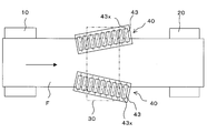
- a stretching apparatus 1 which is used to stretch a film F in the transport direction in a process of producing the film F, is shown.
- the stretching device 1 is a delivery mechanism for delivering the film F, and a take-up roller, which is a take-up mechanism for taking out the delivered film F at a speed faster than that of the film F delivered by the delivery mechanism. It has twenty.
- the delivery roller 10 and the take-up roller 20 are individually rotationally driven by a drive mechanism (not shown), and the film F is conveyed from the delivery roller 10 side to the take-up roller 20 side.
- the circumferential speed of the winding roller 20 is larger than the circumferential speed of the feeding roller 10, and the film F is pulled between the feeding roller 10 and the winding roller 20 due to the circumferential speed difference between them, and as a result, the film F is It is stretched in the MD direction.
- the draw ratio of the film F can be adjusted by appropriately setting the peripheral speed ratio between the delivery roller 10 and the take-up roller 20.
- any roller generally used in this kind of drawing apparatus is used, and in order to draw the film at a desired drawing ratio, the film F slips on the roller surface. It is important not to In order to prevent the film F from slipping, at least one of the delivery roller 10 and the take-up roller 20 is a suction roller (suction roller) having a large number of suction holes on the surface to suction the film F by negative pressure. It can be done. Also, the delivery mechanism and the take-off mechanism can be configured by a roller group consisting of a plurality of rollers, and in this case also, at least one roller can be used as a suction roller.
- a heating furnace 30 for heating the film F during conveyance is installed between the feed roller 10 and the take-up roller 20, a heating furnace 30 for heating the film F during conveyance.
- the heating furnace 30 has an inlet side opening 31 and an outlet side opening 32.
- the film F is heated by a heat source (not shown) until it enters the heating furnace 30 through the inlet side opening 31 and exits the heating furnace 30 through the outlet side opening 32 and the heated portion of the film F Is drawn preferentially.
- Each film holding unit 40 has an upper plate 42 and a lower plate 45 which are disposed facing each other up and down with a transport path of the film F from the feeding roller 10 to the winding roller 20.
- the upper plate 42 is supported by a linear actuator 41 such as an air cylinder, a hydraulic cylinder, or an electric cylinder so as to be movable in the vertical direction, which is the opposite direction to the lower plate 45. Is rotatably supported.
- a linear actuator 41 such as an air cylinder, a hydraulic cylinder, or an electric cylinder so as to be movable in the vertical direction, which is the opposite direction to the lower plate 45.
- the plurality of upper pressing rollers 43 are arranged in parallel at intervals in the MD direction (arrow direction) of the film F, and the rotation axis 43 x is the film F in the TD direction of the film F.
- the outer peripheral surface is directed obliquely outward in the TD direction of the film F.
- each upper pressure roller 43 The length, diameter, spacing, and inclination of the film F relative to the TD direction of each upper pressure roller 43 are preferably identical to each other, but at least one of the length, diameter, spacing, and inclination may be different.
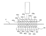
- the lower plate 45 individually supports the plurality of lower pressure rollers 46 on the upper surface side thereof via the plurality of springs 47 and the plurality of sub plates 45a.
- the lower end of the spring 47 is fixed to the lower plate 45, and can be elastically deformed by receiving a force from the upper plate 42 toward the lower plate 45.
- a spring 47 for example, a compression coil spring can be used.
- One sub plate 45 a is fixed to the upper end of each spring 47, and each sub plate 45 a rotatably supports one lower pressing roller 46. Therefore, the plurality of lower pressing rollers 46 are supported so as to be elastically displaced up and down individually via the plurality of springs 47.
- the plurality of lower pressing rollers 46 supported in this manner are located below the transport path of the film F.
- Each lower pressing roller 46 is disposed at a position opposed to the corresponding upper pressing roller 43 in the vertical direction so that the film F can be sandwiched from the upper and lower sides in cooperation with each upper pressing roller 43. Therefore, the lower pressing roller 46 is also arranged in parallel at intervals in the MD direction of the film F as the upper pressing roller 43, and when viewed from the MD direction downstream side of the film F, the outer circumferential surface is the film F The TD direction is facing diagonally outward.
- the length, diameter, spacing and inclination of each lower pressing roller 46 may be different or the same as each other as long as the length, diameter, spacing and inclination of the opposing upper pressing roller 43 .
- the force (pressure force) for sandwiching the film F by the upper pressing roller 43 and the lower pressing roller 46 can be adjusted by appropriately setting the position of the upper pressing roller 43 in the vertical direction by the linear actuator 41.
- the film holding unit 40 is disposed inside the heating furnace 30, but in the present embodiment, the entire film holding unit 40 is not disposed inside the heating furnace 30, and the MD direction upstream of the film F On the side and the downstream side, a part of the film holding unit 40 protrudes from the inlet opening 31 and the outlet opening 32. As a result, a part of the upper pressing roller 43 and the lower pressing roller 46 also project from the inlet side opening 31 and the outlet side opening 32 on the upstream side and the downstream side of the film F in the MD direction.
- the film F delivered from the delivery roller 10 is heated by the heating furnace 30 along the transport path until it is taken up by the take-up roller 20 And stretched in this heated area.
- the film F is vertically sandwiched at both ends in the TD direction by the plurality of upper pressing rollers 43 and the plurality of lower pressing rollers 46 of the film pressing unit 40. Since the upper pressing roller 43 and the lower pressing roller 46 are rotatably supported, when the film F is conveyed from the delivery roller 10 side to the take-up roller 20 while being sandwiched therebetween, the upper pressing roller 43 and the lower The pressure roller 46 is rotated by the friction with the film F.
- the upper pressure roller 43 and the lower pressure roller 46 are supported by the upper pressure roller 43 and the lower pressure roller 46, since the rotary shaft is supported obliquely downward in the TD direction of the film F toward the downstream side of the film F in the MD direction.
- the force in the TD direction of the film F is exerted on the both ends of the film F in the TD direction by the friction between the upper pressing roller 43 and the lower pressing roller 46. While this force reduces the width of the film F by stretching, it exerts a force that restrains the film F. As a result, the neck-in of the film F is suppressed.
- both end portions in the TD direction of the film F are mechanically restrained by the upper pressing roller 43 and the lower pressing roller 46, the neck-in is suppressed regardless of the heating condition. Can. Moreover, the rotation of the upper pressing roller 43 and the lower pressing roller 46 follows the conveyance of the film F, and in the MD direction of the film F, the restraining force of the film F by the upper pressing roller 43 and the lower pressing roller 46 is small. There is almost no influence on the stretching of the film F.
- the upper pressing roller 43 and the lower pressing roller 46 are respectively arranged in plurality at intervals in the MD direction of the film F, the region in which the necking of the film F may occur is taken as the MD direction of the film F Can be held in a wide range. As a result, neck-in of the film F can be effectively suppressed.
- the range in which the upper pressing rollers 43a to 43i press the film F in the MD direction of the film F when considering a to i, two ranges adjacent to the MD direction of the film F (a and b, b and c, c and d, d and e, e and f, f and g, g and h, h and It is preferable to set the length, spacing, and inclination angle of the rotation axis of the film F with respect to the TD direction so that i) contacts or partially overlaps each other.
- the plurality of lower pressing rollers (not shown in FIG. 3) correspond to the upper pressing rollers 43a to 43i by the same number as the upper pressing rollers 43a to 43i, and each faces the upper pressing rollers 43a to 43i. Arranged as.
- the film F is formed by the pair of upper pressing roller and lower pressing roller from the range a to the range i in the MD direction of the film F. Since it is pinched, neck-in can be suppressed more effectively.
- the film F is held by the plurality of upper pressing rollers 43 and the plurality of lower pressing rollers 46, in order to effectively suppress the neck-in, all the upper pressing rollers 43 and the lower pressing rollers 46 It is important that the film F be held in pairs. That is, the upper pressing rollers 43 are attached such that the distances in the direction perpendicular to the lower surface of the upper plate 42 are equal to each other, and the lower pressing rollers 46 are perpendicular to the upper surface of the lower plate 45 It is important that they be mounted so that the distances in one direction are equal to one another.
- one lower presser roller 46 e is, as illustrated in FIG. 4, due to variations in attachment of the upper presser roller 43 and the lower presser roller 46 to the upper plate 42 and the lower plate 45, respectively.
- the film F is attached to the upper surface of the lower plate 45 at a position projecting beyond the other lower pressing rollers 46a to 46d and 46f to 46i, the film F is formed only by the lower pressing roller 46e and the upper pressing roller 43e opposed thereto. It will be pinched.
- all the lower pressing rollers 46 are individually supported by the lower plate 45 via the springs 47, and the position of the upper plate 42 can be adjusted up and down by the linear actuator 41. Since the upper plate 42 is moved closer to the lower plate 45 by the linear actuator 41, the spring 47 supporting the lower presser roller 46e in the projecting position is opposed to the upper presser roller 43e. , So that all the lower pressing rollers can hold the film F with the upper pressing rollers.
- the upper pressing roller 43 and the lower pressing roller 43 are combined by combining the support of the lower pressing roller 46 via the spring 47 and the structure in which the upper pressing roller 43 can move up and down by the linear actuator 41 as described above.
- the sandwiching force of the film F by 46 and can be adjusted according to the draw ratio of the film F, and the like.
- the upper plate 42 is vertically movable by the linear actuator 41 in the embodiment described above
- the lower plate 45 may be movable in the vertical direction, and the upper plate 42 and the lower plate may be vertically movable. Both 45 may be movable up and down.
- the plurality of lower pressing rollers 46 are individually supported by the plurality of springs 47 on the lower plate 45, but the plurality of upper pressing rollers 43 are individually vertically moved by the plurality of springs.
- the upper presser roller 43 and the lower presser roller 4 may be supported so as to be elastically deformable in the upper and lower directions, respectively.
- the heating system of the heating furnace 30 may be any heating system as long as it can heat the film F to an extent that can soften the film F, and examples thereof include heating with infrared rays, heating with hot air, and combinations thereof. For uniform stretching, it is preferable to be able to heat the entire film as uniformly as possible.
- the film pressing units 40 are installed at both ends of the film F in the TD direction, and both ends of the film F in the TD direction are slightly less likely to be heated than other parts. Therefore, in consideration of the simplicity of the apparatus, the cost, etc., in the present embodiment, the upper pressing roller 43 and the lower pressing roller 46 in contact with the film F are also heated by the infrared heating method. It is preferable to use a heating furnace by a hot air system which can also indirectly heat both end portions in the width direction.
- the heating furnace 30 heats the film F in the middle of conveyance, and therefore, has the inlet side opening 31 and the outlet side opening 32 for passing the film F in view of the structure, and these inlet side openings A portion of the air heated in the heating furnace 30 flows out through the portion 31 and the outlet opening 32. Therefore, depending on the temperature in the heating furnace 30 and the size of the openings 31, 32, the film F may be stretched near the openings 31, 32 even outside the heating furnace 30.
- the film pressing unit 40 is outside the heating furnace 30 via the inlet side opening 31 and the outlet side opening 32 on the upstream and downstream sides of the film F in the MD direction.
- a portion of the plurality of upper pressing rollers 43 and a portion of the plurality of lower pressing rollers 46 are disposed outside the heating furnace 30.
- the entire film holding unit 40 may be disposed inside the heating furnace 30 if the outflow of the heated air from the inlet side opening 31 and the outlet side opening 32 is not considered so much.
- the plurality of upper pressing rollers 43 (and hence the lower pressing roller 46) move from the upstream side to the downstream side of the film F in the MD direction.
- An example is shown in which the device is disposed out of alignment in the TD direction. This is because the rotation shaft of the upper pressing roller 43 is disposed in parallel with the width direction of the rectangular upper plate 42, and the upper plate 42 is installed in an inclined posture.
- the plurality of upper pressing rollers 43 themselves are attached such that the rotation shaft 43x is oblique to the TD direction of the upper plate 42, and each upper pressing roller in the TD direction of the film F It is also possible to arrange the 43 positions equally. In this case, of course, the lower presser roller 46 is similarly arranged. The arrangement of the upper pressing roller 43 and the lower pressing roller 46 as described above can well suppress the neck-in at the time of stretching.
- the upper pressing roller 43 and the lower pressing roller 46 rotate as the film F is transported, and it is the neck-in that the rotation accompanying the transport of the film F is performed smoothly.
- the peripheral surfaces of these pressing rollers 43 and 46 are roughened by sanding or embossing such as embossing, and work between the pressing roller 43 and the film F It is preferable that the frictional force be increased.
- the upper pressure roller 43 and the lower pressure roller 46 may be rubber rollers, or these rubber rollers may be pneumatically expanded hollow air rollers to increase the frictional force acting on the film F. It is also good.
- the inclination angles of the rotation shafts of the upper and lower pressing rollers 43 and 46 with respect to the TD direction of the film F are set in accordance with the stretching ratio of the film F in the MD direction. Since the neck-in amount of the film F increases as the stretch ratio increases, it is necessary to constrain both ends in the TD direction of the film F so as not to cause neck-in. In order to increase the restraining force of the film F in the TD direction, it is preferable that the inclination angle be large. However, if the inclination angle is increased too much, the restraining force in the MD direction of the film F is increased, which may make it impossible to appropriately perform the stretching.
- the inclination angle has an appropriate range, and the preferable range is more than 0 ° and less than 45 °, more preferably more than 0 ° and not more than 30 °, still more preferably more than 0 ° It is 15 degrees or less.
- a mechanism having at least one delivery roller and at least one take-up roller has been shown as the delivery mechanism and the take-up mechanism in the present invention.
- the delivery mechanism and the take-off mechanism are not limited to the mechanism for transporting the film by the roller, and for example, the film gripping member moving in the MD direction of the film while gripping the end of the film in the TD direction
- These delivery side and take-up by arranging the take-up side film gripping members on both sides in the TD direction of the film on the take-up side and at a speed higher than the speed of the film delivered from the delivery side holding member.
- the side gripping members can also be used as delivery and take-off mechanisms, respectively.
- at least one of the delivery mechanism and the take-up mechanism can be configured by a combination of a roller and a gripping member.
- a molten resin is formed into a film to form a film (S101).
- the film may be molded by, for example, extrusion-molding, solution-casting, and calendaring.
- the formed film is conveyed by a roller, it is stretched in the MD direction (S102).
- a neck-in usually occurs, but the neck-in is suppressed by using the above-described stretching apparatus 1 of the present embodiment.
- the film stretched in the MD direction is then stretched in the TD direction (S103).
- a tenter device or the like can be used for stretching in the TD direction.
- neck-in is caused by stretching in the MD direction, so it is necessary to extra-stretch by the amount of the width reduced by neck-in in addition to the desired stretching amount, which may cause film breakage Also, the mechanical load on the stretching apparatus was large.
- the film stretched in the TD direction is cured (cure) (S104), and wound on a roller (S105) to produce a biaxially stretched film.
- Methods of curing the film include heating, utilization of a catalyst, irradiation of ultraviolet light (UV), irradiation of electron beam, and a combination of them.
- the film is stretched in the MD direction and the TD direction at a desired stretch ratio, whereby the desired thermal linear expansion in the MD direction and the TD direction
- a biaxially stretched film having a coefficient can be produced with significantly reduced film breakage when stretched in the TD direction.
- the stretching apparatus of the present invention can be used for stretching of various films in the MD direction, but among the films, it can be particularly preferably used for stretching of a self-supporting film in the production of a polyimide film.
- a solvent solution of a polyimide precursor is cast on a support to make a self-supporting film, and a self-supporting film obtained in the first step is transported.
- a second step of heating is included, and the second step includes stretching in the MD direction of the self-supporting film with the stretching device. More specifically, as shown in FIG. 6, in the method of producing a polyimide film of the present invention, a solvent solution of a polyimide precursor is cast on a support (S101) to form a self-supporting film as a first step And a second step of heating for the purpose of heat treatment including imidization and / or stretching while conveying the self-supporting film. The second step includes stretching the self-supporting film in the transport direction (S102), then stretching in the width direction (S103), and heat curing (S104). The polyimide film finally manufactured by heat curing is wound around a roller (S105).
- the “step of film forming” step (S101), the “MD stretching” step (S102), and the “TD stretching” step (FIG. 6) are the “film forming” step (S101), the “MD stretching” step (S102) in FIG. S103) corresponds to the “cure” step (S104) and the “roll-up” step (S105).
- the stretching apparatus of the present invention is used in the MD stretching step among these steps. Therefore, when using the extending
- a polyimide film can be produced by thermal imidization, chemical imidization, or a method using thermal imidization and chemical imidization in combination.
- a polyimide precursor for forming a self-supporting film in a 1st process well-known polyimide precursors, such as a polyamic acid obtained from a well-known acid component and a diamine component, can be used.
- the finally produced polyimide layer may be composed of a single layer or a multilayer composed of different components.
- at least one layer is preferably a layer composed of heat-resistant polyimide.
- a layer composed of a thermocompression-bondable polyimide is formed on one side or both sides of a layer composed of a heat resistant polyimide, Examples in which the layer is excellent, examples in which at least one layer is formed by a layer excellent in transparency or non-transparency, and the like can be given.
- the self-supporting film may also be composed of one layer or multiple layers different in the component of the polyimide precursor, corresponding to the polyimide film finally manufactured.
- a combination comprising 3,3 ′, 4,4′-biphenyltetracarboxylic acid dianhydride (s-BPDA), p-phenylenediamine (PPD) and optionally 4,4-diaminodiphenylether (DADE).
- s-BPDA 4,4′-biphenyltetracarboxylic acid dianhydride
- PPD p-phenylenediamine
- DADE 4,4-diaminodiphenylether
- a combination comprising 3,3 ′, 4,4′-biphenyltetracarboxylic dianhydride and pyromellitic dianhydride (PMDA), p-phenylenediamine and optionally 4,4-diaminodiphenylether.
- PMDA pyromellitic dianhydride
- BPDA / PMDA is preferably 0/100 to 90/10.
- PPD and DADE are used in combination, PPD / (DADE is preferably 90/10 to 10/90, for example.
- DADE / PPD is preferably 90/10 to 10/90.
- part or all of 4,4-diaminodiphenyl ether may be replaced by 3,4'-diaminodiphenyl ether or other diamines shown below depending on the purpose.
- an acid component capable of obtaining a heat-resistant polyimide other than the acid components shown above, 2,3,3 ′, 4′-biphenyltetracarboxylic acid dianhydride, 3,3 to the extent that the target characteristics are not impaired.
- thermocompression-bondable polyimide is (1) 3,3 ', 4,4'-biphenyltetracarboxylic dianhydride, 2,3,3', 4'-biphenyltetracarboxylic dianhydride, pyromellitic dianhydride, 3,3 '1,4,4'-benzophenonetetracarboxylic acid dianhydride, bis (3,4-dicarboxyphenyl) ether dianhydride, bis (3,4-dicarboxyphenyl) sulfide dianhydride, bis (3,4-) Dicarboxyphenyl) sulfone dianhydride, bis (3,4-dicarboxyphenyl) methane dianhydride, 2,2-bis (3,4-dicarboxyphenyl) propane dianhydride and 1,4-hydroquinone dibenzoate
- An acid component containing at least one component selected from acid dianhydrides such as -3,3 ', 4,4'-t
- At least one component selected from 3,3 ′, 4,4′-biphenyltetracarboxylic acid dianhydride and 2,3,3 ′, 4′-biphenyltetracarboxylic acid dianhydride acid dianhydride A seed-containing acid component, preferably an acid component containing at least 70 mol% or more, more preferably 80 mol% or more, more preferably 90 mol% or more of these acid components;
- the diamine component 1,3-bis (4-aminophenoxy) benzene, 1,3-bis (3-aminophenoxy) benzene 4,4′-bis (3-aminophenoxy) biphenyl, bis [4 -(3-Aminophenoxy) phenyl] sulfone, bis [4- (3-aminophenoxy) phenyl] ether, 2,2-bis [4- (3-
- thermocompression-bondable polyimide As a diamine component from which a thermocompression-bondable polyimide can be obtained, p-phenylenediamine, m-phenylenediamine, 2,4-toluenediamine, and 3, within the range not impairing the characteristics of the present invention other than the diamine components shown above.
- the synthesis of the polyimide precursor can be carried out by a known method, for example, by random polymerization or block polymerization of an acid component such as about equimolar aromatic tetracarboxylic acid dianhydride and a diamine component in an organic solvent Is achieved by May also be mixed with the reaction conditions was keep two or more polyimide precursors in which either of these two components is excessive, the respective polyimide precursor solution together.
- the polyimide precursor solution thus obtained can be used for producing a self-supporting film as it is or, if necessary, removing or adding a solvent.
- the polyimide precursor solution is heated to 150 to 250 ° C. or added with an imidization agent and reacted at a temperature of 150 ° C. or less, particularly 15 to 50 ° C. to form imide cyclization
- the solvent is then evaporated or precipitated in a poor solvent to form a powder.
- the powder can be dissolved in an organic solvent to obtain an organic solvent solution of polyimide.
- organic solvent of the polyimide precursor solution examples include N-methyl-2-pyrrolidone, N, N-dimethylformamide, N, N-dimethylacetamide, N, N-diethylacetamide and the like. These organic solvents may be used alone or in combination of two or more.
- fine particles such as an imidation catalyst, an organic phosphorus-containing compound, and inorganic fine particles and organic fine particles may be added to the polyimide precursor solution.
- a substituted or unsubstituted nitrogen-containing heterocyclic compound As the imidation catalyst, a substituted or unsubstituted nitrogen-containing heterocyclic compound, an N-oxide compound of the nitrogen-containing heterocyclic compound, a substituted or unsubstituted amino acid compound, an aromatic hydrocarbon compound having a hydroxyl group or an aromatic complex Cyclic compounds, in particular, lower ones such as 1,2-dimethylimidazole, N-methylimidazole, N-benzyl-2-methylimidazole, 2-methylimidazole, 2-ethyl-4-methylimidazole, 5-methylbenzimidazole Alkylimidazole, benzimidazole such as N-benzyl-2-methylimidazole, isoquinoline, 3,5-dimethylpyridine, 3,4-dimethylpyridine, 2,5-dimethylpyridine, 2,4-dimethylpyridine, 4-n- Substituted pyridine such as propylpyridine It can be used to apply
- the amount of the imidization catalyst used is preferably about 0.01 to 2 equivalents, and more preferably 0.02 to 1 equivalents, with respect to the amic acid unit of the polyamic acid.
- Use of the imidization catalyst may improve the physical properties of the resulting polyimide film, in particular, the elongation and tear resistance.
- a chemical imidization agent in which a dehydrated ring-closing agent and an organic amine are combined is generally contained in a polyimide precursor solution.
- dehydrated ring-closing agents include dicyclohexylcarbodiimide and acid anhydrides such as acetic anhydride, propionic acid anhydride, valeric acid anhydride, benzoic acid anhydride, benzoic acid anhydride and trifluoroacetic acid dianhydride, and organic amines such as picoline and quinoline And isoquinoline, pyridine and the like, but not limited thereto.
- a polyimide precursor solution As a polyimide precursor solution, it can be cast on a support, a self-supporting film can be peeled from the support, and then a self-supporting film can be formed which can be stretched in at least one direction in the second step.
- the viscosity of the polyimide precursor solution can be appropriately set, such as the type of polymer, the degree of polymerization, the concentration, and the types and concentrations of various additives to be added to the solution as required.
- the concentration of the polyimide precursor in the polyimide precursor solution is preferably 5 to 30% by mass, more preferably 10 to 25% by mass, and still more preferably 15 to 20% by mass.
- the solution viscosity of the polyimide precursor solution is preferably 100 to 10000 poise, preferably 400 to 5000 poise, and more preferably 1000 to 3000 poise.
- the die contains one or more types of polyimide precursor solvent
- the solution is supplied, and extruded from the discharge port (lip portion) of the die as a single layer or multilayer thin film on a support (endless belt, drum, etc.) to obtain a substantially uniform thickness of the solvent solution of the polyimide precursor.
- the film can be formed at a temperature at which the imidization of the polyimide precursor does not proceed completely while moving the support (endless belt, drum, etc.) inside the casting furnace and a part or most of the organic solvent can be removed. Heat to temperature to peel the self-supporting film from the support.
- a self-supporting film is formed from a solvent solution of a polyimide precursor of a specific composition, and then a solvent solution of a polyimide precursor of a different composition is cast on the surface.
- Multilayer self-supporting films can also be produced by heating in a casting furnace.
- a known material can be used as the support, but it is preferable that the surface is made of a metal material such as a stainless steel material, a resin material such as polyethylene terephthalate, a stainless steel belt, stainless steel roll, polyethylene terephthalate Belts can be mentioned.
- the surface of the support is preferably capable of uniformly forming a thin film of solvent.
- the surface of the support may be smooth, or grooves or embossments may be formed on the surface. It is particularly preferred to be smooth.
- the heating temperature inside the casting furnace may be a temperature at which the imidization of the polyimide precursor does not proceed completely and a temperature at which part or most of the organic solvent can be removed, for example, in the range of 30 to 200 ° C.
- the temperature is preferably 100 to 200.degree.
- the self-supporting film is in the semi-cured state or in the dried state before it.
- the state of semi-hardened or before means that it is in a self-supporting state by heating and / or chemical imidization.
- the self-supporting film may be any one that can be peeled off from the support, and the solvent content and the imidation ratio may be in any range.
- the self-supporting film may be a solution (for example, a surface treatment agent, a polyimide precursor, a polyimide, etc. may be included) on one side or both sides of the self-supporting film after peeling off the support. May be applied, sprayed, dipped or the like, and the coating solvent may be mainly removed by means such as drying or extraction if necessary.
- a solution for example, a surface treatment agent, a polyimide precursor, a polyimide, etc. may be included
- various coupling agents such as silane coupling agents, borane coupling agents, aluminum coupling agents, aluminum chelating agents, titanate coupling agents, iron coupling agents, copper coupling agents, and chelates Agents can be mentioned.
- the solvent content and imidization rate of the self-supporting film can be appropriately set according to the polyimide film intended for production.
- the solvent content means the content of a volatilizable component including generated water, in addition to the solvent in the precursor solution.
- the imidation ratio is 1 to 80%, preferably 5 to 40%
- the solvent content is preferably 10 to 60% by mass, More preferably, it is 25 to 45% by mass.
- the imidization ratio is 50 to 100%, preferably 70 to 100%, and the solvent content of the polyimide precursor is preferably 10 to 80% by mass, more preferably 20 to 70%. %.
- the self-supporting film produced in the first step is sent to the second step after the surface treatment agent is applied if necessary.
- the self-supporting film produced in the first step is subjected to heat treatment (stretching and heat curing) to form a polyimide film having desired physical properties.
- the above-described stretching apparatus is used in stretching the self-supporting film in the MD direction.
- both end portions of the self-supporting film in the TD direction are sandwiched by a film pressing unit having a plurality of upper pressing rollers and lower pressing rollers arranged obliquely as described above. Since stretching is performed, the occurrence of neck-in can be favorably suppressed.
- the self-supporting film is preferably stretched in the TD direction by a tenter device.
- stretching in the MD direction causes necking-in, in addition to the desired stretching amount, it is necessary to stretch extra by the amount of the width reduced by neck-in, which causes film breakage.
- the mechanical burden on the stretching device was also large.
- neck-in is suppressed by using the above-described stretching apparatus for stretching in the MD direction, it is not necessary to increase the stretching ratio in the TD direction as in the prior art. As a result, the film breakage can be significantly reduced, the film can be stretched in the TD direction at a desired stretching ratio, and a polyimide film having a desired linear expansion coefficient can be obtained.
- the self-supporting film is transported by moving at a predetermined speed in a heating zone at a predetermined temperature, during which the self-supporting film is heat-treated to promote imidization (thermal curing), and finally the polyimide A film is obtained.
- a tenter device can be used for stretching the self-supporting film in the TD direction.
- the tenter device has a pair of tenter chains for gripping both ends of the self-supporting film in the TD direction, and the spacing of the tenter chains is changed so as to expand while the chain is moving in the MD direction. Can stretch the self-supporting film in the TD direction.
- a tenter device can be used to transport the self-supporting film.
- the tenter apparatus can be used to continuously or simultaneously heat and cure the self-supporting film in the TD direction.
- the maximum temperature is in the range of 200 to 600 ° C., preferably in the range of 350 to 550 ° C., particularly preferably in the range of 300 to 500 ° C. It is preferable to heat gradually in 5 hours.
- the solvent and the like are sufficiently removed from the self-supporting film so that the content of the volatile matter composed of the organic solvent and the generated water and the like in the finally obtained polyimide film is 1% by weight or less. The imidization of the constituent polymer is sufficiently carried out.
- the heating zone preferably also has a temperature gradient and may be divided into several blocks with different heating temperatures.
- One example is primary heat treatment for about 0.5 to 30 minutes at a relatively low temperature of about 100 to 170 ° C., and then for about 0.5 to 30 minutes at a temperature of 170 to 220 ° C.
- a third heat treatment is performed at a high temperature of 220 to 400 ° C. for about 0.5 to 30 minutes, and if necessary, a fourth heat treatment at a high temperature of 400 to 600 ° C.
- primary heat treatment is carried out at 80 to 240 ° C.
- heat treatment is optionally carried out at an intermediate heating temperature
- final heat treatment is carried out at 350 to 600 ° C.
- the above heat treatment can be performed using various known heating devices such as a hot air furnace, an infrared heating furnace, and the like.
- the heat treatment such as the initial heating temperature, the intermediate heating temperature and / or the final heating temperature of the self-supporting film is preferably performed under an inert gas such as nitrogen or argon or a heating gas atmosphere such as air.
- a polyimide film is manufactured in a long shape by the above manufacturing method, generally, a portion obtained by cutting and excluding both ends of a self-supporting film held in the TD direction by a tenter is wound in a roll It is preserved and provided to the next processing.
- the thickness of the polyimide film is not particularly limited as long as it is appropriately selected, but the thickness is 150 ⁇ m or less, preferably 5 to 120 ⁇ m, more preferably 8 to 80 ⁇ m, more preferably 6 to 50 ⁇ m, still more preferably 7 It can be up to 40 ⁇ m, particularly preferably 8 to 35 ⁇ m.
- the stretching apparatus shown in FIG. 1 or the like is used in the second step of imidation and / or heat treatment of the self-supporting film among the steps of producing the polyimide film. Since this stretching apparatus can well suppress neck-in, it is possible to reduce film breakage in the subsequent stretching in the TD direction. As a result, it is possible to efficiently produce a polyimide film excellent in thermal dimensional stability having a desired linear expansion coefficient and being stretched in the MD direction and the TD direction with a desired stretching ratio.
- the linear expansion coefficient of the polyimide film can be controlled in the range of 5 to 15 ppm / ° C. in both the MD and TD directions.
- Example 1 the neck-in rate was determined when the polyimide film (self-supporting film) was stretched in the MD direction under various conditions.
- Example 1-1 P-phenylenediamine (PPD) as a diamine component and 3,3 ', 4,4'-biphenyltetracarboxylic acid dianhydride (s-BPDA as acid component) using N, N-dimethylacetamide as a solvent And a polyamic acid solution (polyimide precursor solution).
- PPD P-phenylenediamine
- s-BPDA 3,3 ', 4,4'-biphenyltetracarboxylic acid dianhydride
- N, N-dimethylacetamide as a solvent
- a polyamic acid solution polyimide precursor solution
- a polyimide film (self-supporting film) formed to a width of 270 mm was stretched in the MD direction, and the neck-in rate was measured.
- the film holding unit 40 had ten upper holding rollers 43 and ten lower holding rollers 46 respectively.
- the upper pressure roller 43 and the lower pressure roller 46 had an angle of inclination of 25 °, a diameter of 20 mm, and a length of 50 mm.
- the pitch between the shafts of the adjacent rollers was 22 mm.
- the material of the upper pressing roller 43 and the lower pressing roller 46 is made of stainless steel (SUS 304), and the surface roughness Ra is made 2 to 3 ⁇ m by subjecting the surface to a shot brass treatment.
- an air cylinder diameter 63 mm
- the upper pressure roller 43 and the lower pressure roller 46 grip the self-supporting film (polyimide film) did.
- the heating furnace 30 used the thing by a hot air for a heating system, and set the inside of the heating furnace 30 so that the temperature was 120 degreeC and the average wind speed of a hot air might be 0.7 m / s.
- the heating time of the self-supporting film by the heating furnace 30 was 15 seconds.
- the heating furnace 30 has a width capable of heating the full width of the film, and the upper pressing roller 43 and the lower pressing roller 46 partially out of the heating furnace 30 from the inlet side opening and the outlet side opening It was set as the structure which hold
- the stretch ratio was 9.17%, and the neck-in ratio was 0.74%.
- Example 1-2 Using a stretching apparatus configured in the same manner as Example 1-1 except that the lower pressing roller 46 is supported without the spring 47 and that the heating system of the heating furnace 30 is by infrared irradiation.
- the self-supporting film (polyimide film) was stretched, and the stretch ratio and the neck-in ratio were determined in the same manner as in Example 1-1.
- the stretch ratio was 8.67% and the neck-in ratio was 2.24%.
- Example 1-1 A self-supporting film (polyimide film) is stretched using the stretching apparatus not equipped with the film holding unit 40 and the other conditions are the same as in Example 1-2, and the stretching ratio and the stretching ratio and the same as in Example 1-1. The neck-in rate was determined. As a result of stretching, the stretch ratio was 9.24% and the neck-in ratio was 5.73%.
- the neck-in rate is reduced to half or less compared to the case where it is not so even though the stretching rate is about the same. I understand that.
- the neck-in ratio can be further reduced by combining the lower pressure roller with a spring and heating the film with hot air.
- Example 2 In Example 2, the set stretching ratio of the device when the polyimide film (self-supporting film) is stretched, and the actual stretching ratio measured from the polyimide film obtained by performing the heat curing after stretching the self-supporting film, The relationship with the thermal linear expansion coefficient was investigated.
- the linear expansion coefficient was measured using a thermomechanical analyzer TMA / SS 6100 manufactured by Seiko Instruments Inc., and the average linear expansion coefficient at 50 to 200 ° C. when the temperature was raised at a rate of 20 ° C./min.
- Example 2-1 The formed polyimide film (self-supporting film) was stretched in the MD direction using the same stretching apparatus 1 as that used in Example 1-1. The stretch ratio was set to 12%. The pressure of the air introduced into the air cylinder for holding the self-supporting film (polyimide film) between the upper pressing roller 43 and the lower pressing roller 46 was set to 0.06 MPa. Next, the self-supporting film (polyimide film) stretched in the MD direction was stretched in the TD direction using a tenter apparatus to obtain a sequentially biaxially stretched film. The draw ratio in the width direction at this time was set to 12%. The stretching temperature and time were 140 to 170 ° C. ⁇ 143 seconds.
- Example 2-1 A self-supporting film (polyimide film) was stretched in the MD and TD directions using the stretching apparatus not equipped with the film holding unit 40, and the other conditions were the same as in Example 2-1, and the sequentially biaxially stretched film was Obtained. Each stretch ratio was set to 12%. When the linear expansion coefficient of the obtained biaxially stretched film was measured, it was 4.33 ppm / ° C. for MD and 11.22 ppm / ° C. for TD. The actual stretch ratio was 11.9% in the MD direction, 8.0% in the TD direction, and the neck-in rate was 6.93%.
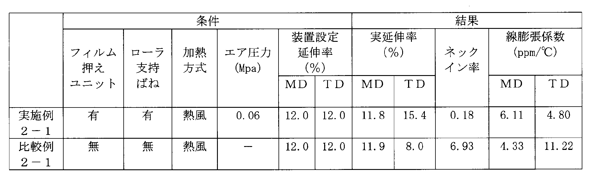
- Example 2-1 The main stretching conditions of Example 2-1 and Comparative Example 2-1 and the measurement results of the thermal linear expansion coefficient and the like are shown in Table 2.
- Example 2-1 From Table 2, in Example 2-1, it can be seen that neck-in hardly occurs due to the film holding unit at the time of MD stretching. Almost no neck-in occurs to ensure the desired TD stretching, thereby reducing the linear expansion coefficient in the TD direction.
- Comparative Example 2-1 since the film holding unit is not used, neck-in occurs largely at the time of MD stretching. As a result, in spite of the same device setting draw ratio in the TD direction as that of Example 2-1, the actual draw ratio becomes smaller due to the neck-in. As a result, the linear expansion coefficient in the TD direction is large. In order to lower this value, it is necessary to further increase the device setting stretch ratio in the TD direction, which places a burden on the tenter device.
- Example 3 In Example 3, plural types of polyimide films having different stretch ratios of a self-supporting film were produced, and the linear expansion coefficients in the MD and TD directions were measured for the obtained polyimide films.
- the stretching was performed only in the MD direction and the TD direction, or in the MD direction, and the stretching device in the MD direction used the stretching device having the upper pressing roller 43 and the lower pressing roller 46 shown in FIG.
- the linear expansion coefficient was measured using a thermomechanical analyzer TMA / SS 6100 manufactured by Seiko Instruments Inc., and the average linear expansion coefficient at 50 to 200 ° C. when the temperature was raised at a rate of 20 ° C./min.
- the draw ratio and linear expansion coefficient of the obtained polyimide film are shown in Table 3.
- "stretching ratio” in Table 3 is a setting stretching ratio of a stretching apparatus.
- "o” means that MD stretching was performed using a drawing apparatus provided with the film holding unit, and "x” using a drawing apparatus provided with no film holding unit It means that it was MD stretched.
- the film stretched by the stretching device provided with the film pressing unit at any stretching ratio had a line in the MD. It can be seen that the expansion coefficient is small.
- the reduction effect of the linear expansion coefficient in TD exhibits a tendency similar to that of the MD stretching, and is more remarkable as the stretching ratio is higher. For example, between Example 3-1 and Comparative Example 3-1, although the reduction effect of the linear expansion coefficient in TD is about 20%, Example 3-3 and Comparative Example 3 in which the MD stretch ratio is increased. Between -3, the reduction effect of the linear expansion coefficient in TD is about 50%.
- Example 3-4 which made the TD draw ratio high In comparison with Comparative Example 3-4, the reduction effect of the linear expansion coefficient in TD reaches about 70%.
- the linear expansion coefficient can be reduced from about 15 ppm / ° C. to about 5 ppm / ° C. in the reference example 3-5 by increasing the reduction efficiency.
- the linear expansion coefficient can be controlled to a lower range in the case where the film holding unit is not present. Specifically, the linear expansion coefficient can be controlled in the range of 5 to 15 ppm / ° C. in both the MD direction and the TD direction.
Landscapes
- Engineering & Computer Science (AREA)
- Mechanical Engineering (AREA)
- Chemical & Material Sciences (AREA)
- Manufacturing & Machinery (AREA)
- Materials Engineering (AREA)
- Chemical Kinetics & Catalysis (AREA)
- Medicinal Chemistry (AREA)
- Polymers & Plastics (AREA)
- Organic Chemistry (AREA)
- Health & Medical Sciences (AREA)
- Shaping By String And By Release Of Stress In Plastics And The Like (AREA)
- Manufacture Of Macromolecular Shaped Articles (AREA)
- Registering, Tensioning, Guiding Webs, And Rollers Therefor (AREA)
Abstract
Description
特許文献2:特開2003-123942号公報
ポリイミド前駆体の溶媒溶液を支持体上にキャストし、自己支持性フィルムとする第1工程と、
自己支持性フィルムを搬送しながら加熱処理する第2工程とを有し、
第2工程は、延伸装置によって自己支持性フィルムをMD方向に延伸することを含むポリイミドフィルムの製造方法であって、
延伸装置は、上記本発明の延伸装置であり、フィルムとして自己支持性フィルムを延伸することを特徴とする。
の製造における自己支持性フィルムのMD方向への延伸に特に好ましく用いることができる。
より具体的には、本発明のポリイミドフィルムの製造方法は、図6に示すように、ポリイミド前駆体の溶媒溶液を支持体上にキャストし(S101)、自己支持性フィルムとする第1工程と、この自己支持性フィルムを搬送しながら、イミド化及び/又は延伸を含む熱処理などを目的とする加熱する第2工程とを有する。第2工程は、自己支持性フィルムを搬送方向に延伸すること(S102)と、次いで幅方向に延伸すること(S103)と、熱キュアすること(S104)と、を含む。熱キュアにより最終的に製造されたポリイミドフィルムは、ローラに巻き取られる(S105)。
第1工程において自己支持性フィルムを形成するためのポリイミド前駆体としては、公知の酸成分とジアミン成分とから得られるポリアミック酸などの公知のポリイミド前駆体を用いることができる。
(1)3,3’,4,4’-ビフェニルテトラカルボン酸二無水物、ピロメリット酸二無水物及び1,4-ヒドロキノンジベンゾエート-3,3’,4,4’-テトラカルボン酸二無水物より選ばれる成分を少なくとも1種含む酸成分、好ましくはこれらの酸成分を少なくとも70モル%以上、さらに好ましくは80モル%以上、より好ましくは90モル%以上含む酸成分と、
(2)ジアミン成分としてp-フェニレンジアミン、4,4’-ジアミノジフェニルエーテル、3,4’-ジアミノジフェニルエーテル、m-トリジン及び4,4’-ジアミノベンズアニリドより選ばれる成分を少なくとも1種含むジアミン、好ましくはこれらのジアミン成分を少なくとも70モル%以上、さらに好ましくは80モル%以上、より好ましくは90モル%以上含むジアミン成分とから得られるポリイミドなどを用いることができる。
1)3,3’,4,4’-ビフェニルテトラカルボン酸二無水物(s-BPDA)と、p-フェニレンジアミン(PPD)と、必要により4,4-ジアミノジフェニルエーテル(DADE)を含む組み合わせ。この場合、PPD/DADE(モル比)は100/0~85/15であることが好ましい。
2)3,3’,4,4’-ビフェニルテトラカルボン酸二無水物及びピロメリット酸二無水物(PMDA)と、p-フェニレンジアミンと必要により4,4-ジアミノジフェニルエーテルを含む組み合わせ。この場合、BPDA/PMDAは0/100~90/10であることが好ましい。PPDとDADEを併用する場合、PPD/(DADEは、例えば90/10~10/90が好ましい。
3)ピロメリット酸二無水物と、p-フェニレンジアミン及び4,4-ジアミノジフェニルエーテルの組み合わせ。この場合、DADE/PPDは90/10~10/90であることが好ましい。
4)3,3’,4,4’-ビフェニルテトラカルボン酸二無水物とp-フェニレンジアミンとを主成分(合計100モル%中の50モル%以上)として得られるものを挙げることができる。
(1)3,3’,4,4’-ビフェニルテトラカルボン酸二無水物、2,3,3’,4’-ビフェニルテトラカルボン酸二無水物、ピロメリット酸二無水物、3,3’,4,4’-ベンゾフェノンテトラカルボン酸二無水物、ビス(3,4-ジカルボキシフェニル)エーテル二無水物、ビス(3,4-ジカルボキシフェニル)スルフィド二無水物、ビス(3,4-ジカルボキシフェニル)スルホン二無水物、ビス(3,4-ジカルボキシフェニル)メタン二無水物、2,2-ビス(3,4-ジカルボキシフェニル)プロパン二無水物及び1,4-ヒドロキノンジベンゾエート-3,3’,4,4’-テトラカルボン酸二無水物などの酸二無水物より選ばれる成分を少なくとも1種含む酸成分、好ましくはこれらの酸成分を少なくとも70モル%以上、さらに好ましくは80モル%以上、より好ましくは90モル%以上含む酸成分と、
(2)ジアミン成分としては、1,3-ビス(4-アミノフェノキシ)ベンゼン、1,3-ビス(3-アミノフェノキシ)ベンゼン、1,4-ビス(4-アミノフェノキシ)ベンゼン、3,3’-ジアミノベンゾフェノン、4,4’-ビス(3-アミノフェノキシ)ビフェニル、4,4’-ビス(4-アミノフェノキシ)ビフェニル、ビス[4-(3-アミノフェノキシ)フェニル]ケトン、ビス[4-(4-アミノフェノキシ)フェニル]ケトン、ビス[4-(3-アミノフェノキシ)フェニル]スルフィド、ビス[4-(4-アミノフェノキシ)フェニル]スルフィド、ビス[4-(3-アミノフェノキシ)フェニル]スルホン、ビス[4-(4-アミノフェノキシ)フェニル]スルホン、ビス[4-(3-アミノフェノキシ)フェニル]エーテル、ビス[4-(4-アミノフェノキシ)フェニル]エーテル、2,2-ビス[4-(3-アミノフェノキシ)フェニル]プロパン、2,2-ビス[4-(4-アミノフェノキシ)フェニル]プロパンなどのジアミンより選ばれる成分を少なくとも1種含むジアミン、好ましくはこれらのジアミン成分を少なくとも70モル%以上、さらに好ましくは80モル%以上、より好ましくは90モル%以上含むジアミン成分とから得られるポリイミドなどを用いることができる。
(1)3,3’,4,4’-ビフェニルテトラカルボン酸二無水物及び2,3,3’,4’-ビフェニルテトラカルボン酸二無水物の酸二無水物より選ばれる成分を少なくとも1種含む酸成分、好ましくはこれらの酸成分を少なくとも70モル%以上、さらに好ましくは80モル%以上、より好ましくは90モル%以上含む酸成分と、
(2)ジアミン成分としては、1,3-ビス(4-アミノフェノキシ)ベンゼン、1,3-ビス(3-アミノフェノキシ)ベンゼン4,4’-ビス(3-アミノフェノキシ)ビフェニル、ビス[4-(3-アミノフェノキシ)フェニル]スルホン、ビス[4-(3-アミノフェノキシ)フェニル]エーテル、2,2-ビス[4-(3-アミノフェノキシ)フェニル]プロパン、2,2-ビス[4-(4-アミノフェノキシ)フェニル]プロパンなどのジアミンより選ばれる成分を少なくとも1種含むジアミン、好ましくはこれらのジアミン成分を少なくとも70モル%以上、さらに好ましくは80モル%以上、より好ましくは90モル%以上含むジアミン成分とから得られるポリイミドなどを用いることができる。
第2工程においては、第1工程で製造した自己支持性フィルムを、加熱処理(延伸および熱キュア)して所望の物性を有するポリイミドフィルムとする。本発明では、自己支持性フィルムのMD方向への延伸の際に、前述の延伸装置を用いる。自己支持性フィルムのMD方向への延伸では、自己支持性フィルムのTD方向両端部を、前述のように斜めに配置された複数の上押えローラおよび下押えローラを有するフィルム押えユニットで挟持しながら延伸するので、ネックインの発生を良好に抑制することができる。
実施例1では、様々な条件でポリイミドフィルム(自己支持性フィルム)をMD方向に延伸したときのネックイン率を求めた。
溶媒としてN,N-ジメチルアセトアミドを用いて、ジアミン成分としてのp-フェニレンジアミン(PPD)と、酸成分としての3,3’,4,4’-ビフェニルテトラカルボン酸二無水物(s-BPDA)とを重合反応させて、ポリアミック酸溶液(ポリイミド前駆体溶液)を得た。得られたポリアミック酸溶液を支持体上に流延し、加熱することにより部分イミド化された自己支持性フィルムを得た。


下押えローラ46を、ばね47を介さずに支持したこと、および加熱炉30の加熱方式が赤外線の照射によるものであることの他は実施例1-1と同様に構成された延伸装置を用いて自己支持性フィルム(ポリイミドフィルム)を延伸し、実施例1-1と同様にして延伸率およびネックイン率を求めた。延伸の結果、延伸率は8.67%、ネックイン率は2.24%であった。
フィルム押えユニット40を備えていない延伸装置を用い、他の条件は実施例1-2と同じにして自己支持性フィルム(ポリイミドフィルム)を延伸し、実施例1-1と同様にして延伸率およびネックイン率を求めた。延伸の結果、延伸率は9.24%、ネックイン率は5.73%であった。

実施例2では、ポリイミドフィルム(自己支持性フィルム)を延伸したときの装置の設定延伸率と、自己支持性フィルムを延伸後に熱キュアを実施して得たポリイミドフィルムから計測した実延伸率と、熱線膨張係数との関係を調べた。
線膨張係数は、セイコーインスツル株式会社製の熱機械的分析装置TMA/SS6100を使用し、20℃/分の速度で昇温したときの50~200℃の平均線膨張係数を測定した。
製膜されたポリイミドフィルム(自己支持性フィルム)を、実施例1-1で用いたものと同じ延伸装置1を用いてMD方向に延伸した。延伸率は12%に設定した。上押えローラ43と下押えローラ46とにより自己支持性フィルム(ポリイミドフィルム)を挟持させるためにエアシリンダに導入したエアの圧力は0.06MPaに設定した。次いで、このMD方向に延伸された自己支持性フィルム(ポリイミドフィルム)を、テンター装置を用いてTD方向に延伸し、逐次二軸延伸フィルムを得た。このときの幅方向の延伸率は12%に設定した。延伸温度および時間は140~170℃×143秒とした。
得られたポリイミドフィルムの線膨張係数を測定したところ、MDについては6.11ppm/℃、TDについては4.80ppm/℃であった。また、実施例1と同様にして求めた実延伸率は、MDについては11.8%、TDについては15.4%で、ネックイン率は0.18%であった。
フィルム押えユニット40を備えていない延伸装置を用い、他の条件は実施例2-1と同じにして自己支持性フィルム(ポリイミドフィルム)をMD方向およびTD方向に延伸し、逐次二軸延伸フィルムを得た。それぞれの延伸率の設定は12%とした。得られた二軸延伸フィルムの線膨張係数を測定したところ、MDについては4.33ppm/℃、TDについては11.22ppm/℃であった。また、実延伸率は、MD方向については11.9%、TD方向については8.0%で、ネックイン率は6.93%であった。
実施例3では、自己支持性フィルムの延伸率の異なる複数種のポリイミドフィルムを製造し、得られたポリイミドフィルムについてMD方向およびTD方向の線膨張係数を測定した。延伸は、MD方向およびTD方向、あるいは、MD方向のみについて実施し、MD方向への延伸に、図1等に示した、上押えローラ43および下押えローラ46を有する延伸装置を用いた。線膨張係数は、セイコーインスツル株式会社製の熱機械的分析装置TMA/SS6100を使用し、20℃/分の速度で昇温したときの50~200℃の平均線膨張係数を測定した。

10 繰り出しローラ
20 巻き取りローラ
30 加熱炉
40 フィルム押えユニット
41 リニアアクチュエータ
42 上プレート
43 上押えローラ
45 下プレート
45a サブプレート
46 下押えローラ
47 ばね
Claims (12)
- フィルムを送り出すための送り出し機構と、
前記送り出し機構から送り出されたフィルムを、前記送り出し機構から送り出されるフィルムの速度よりも速い速度で引き取る引き取り機構と、
前記送り出し機構と前記引き取り機構との間でフィルムの幅(TD)方向両端部に配置された2組のフィルム押えユニットと、
を有し、
前記フィルム押えユニットは、
フィルムの搬送経路の上方に、フィルムの搬送(MD)方向に間隔をあけて並列に配置された複数の上押えローラと、
前記複数の上押えローラと協働してフィルムを上下から挟むようにフィルムの搬送経路の下方に上押えローラと対向配置された複数の下押えローラと、
を有し、
前記上押えローラおよび前記下押えローラは、回転軸をフィルムのMD方向下流側に向かってフィルムのTD方向外側に傾いて回転自在に支持されていることを特徴とする延伸装置。 - 前記複数の上押えローラを支持する上プレートと、前記上プレートと対向配置されて前記複数の下押えローラを支持する下プレートとをさらに有する請求項1に記載の延伸装置。
- 前記上プレートおよび前記下プレートの少なくとも一方が上下方向に移動可能に支持されている請求項2に記載の延伸装置。
- 前記複数の上押えローラおよび前記複数の下押えローラの少なくとも一方が、複数の弾性部材を介して個々に上下に弾性変位可能に支持されている請求項2または3に記載の延伸装置。
- 前記送り出し機構と前記引き取り機構との間に、搬送中のフィルムを加熱する加熱炉をさらに有し、前記フィルム押えユニットの少なくとも一部は前記加熱炉の内部に配置されている請求項1から4のいずれか1項に記載の延伸装置。
- 前記加熱炉はフィルムのための入口側開口部および出口側開口部を有し、前記入口側開口部および前記出口側開口部を介して、前記複数の上押えローラのうちの一部および前記複数の下押えローラのうちの一部が前記加熱炉の外部に配置されている請求項5に記載の延伸装置。
- 前記加熱炉は、熱風により前記フィルムを加熱する請求項5または6に記載の延伸装置。
- 前記上押えローラおよび下押えローラは、周面に粗面処理が施されている請求項1から7のいずれか1項に記載の延伸装置。
- 前記送り出し機構と前記引き取り機構とは、いずれもローラである請求項1から8のいずれか1項に記載の延伸装置。
- 前記送り出し機構および前記引き取り機構の少なくとも一方が吸引ローラである請求項9記載の延伸装置。
- ポリイミド前駆体の溶媒溶液を支持体上にキャストし、自己支持性フィルムとする第1工程と、
前記自己支持性フィルムを搬送しながら加熱処理する第2工程とを有し、
前記第2工程は、延伸装置によって前記自己支持性フィルムをMD方向に延伸することを含むポリイミドフィルムの製造方法であって、
前記延伸装置は、請求項1から10のいずれか1項に記載の延伸装置であり、フィルムとして前記自己支持性フィルムを延伸することを特徴とするポリイミドフィルムの製造方法。 - 前記第2工程は、前記延伸装置を用いたMD方向に延伸の後に、前記自己支持性フィルムをTD方向に延伸することを含む請求項11に記載のポリイミドフィルムの製造方法。
Priority Applications (4)
| Application Number | Priority Date | Filing Date | Title |
|---|---|---|---|
| US13/638,527 US9199409B2 (en) | 2010-03-31 | 2011-03-29 | Stretching apparatus and method of manufacturing polyimide film using the same |
| KR1020127028415A KR101796137B1 (ko) | 2010-03-31 | 2011-03-29 | 스트레칭 기구 및 이것을 사용한 폴리이미드 막의 제조 방법 |
| JP2012509487A JP5692220B2 (ja) | 2010-03-31 | 2011-03-29 | 延伸装置およびそれを用いたポリイミドフィルムの製造方法 |
| CN201180026573.6A CN102917858B (zh) | 2010-03-31 | 2011-03-29 | 拉伸设备和使用其制造聚酰亚胺膜的方法 |
Applications Claiming Priority (4)
| Application Number | Priority Date | Filing Date | Title |
|---|---|---|---|
| JP2010-081321 | 2010-03-31 | ||
| JP2010081384 | 2010-03-31 | ||
| JP2010-081384 | 2010-03-31 | ||
| JP2010081321 | 2010-03-31 |
Publications (1)
| Publication Number | Publication Date |
|---|---|
| WO2011125662A1 true WO2011125662A1 (ja) | 2011-10-13 |
Family
ID=44762609
Family Applications (1)
| Application Number | Title | Priority Date | Filing Date |
|---|---|---|---|
| PCT/JP2011/057863 Ceased WO2011125662A1 (ja) | 2010-03-31 | 2011-03-29 | 延伸装置およびそれを用いたポリイミドフィルムの製造方法 |
Country Status (6)
| Country | Link |
|---|---|
| US (1) | US9199409B2 (ja) |
| JP (1) | JP5692220B2 (ja) |
| KR (1) | KR101796137B1 (ja) |
| CN (1) | CN102917858B (ja) |
| TW (1) | TW201202006A (ja) |
| WO (1) | WO2011125662A1 (ja) |
Cited By (11)
| Publication number | Priority date | Publication date | Assignee | Title |
|---|---|---|---|---|
| CN102431160A (zh) * | 2011-12-02 | 2012-05-02 | 浙江格尔泰斯环保特材科技有限公司 | 一种聚四氟乙烯纤维膜预拉伸装置 |
| CN102555220A (zh) * | 2011-12-05 | 2012-07-11 | 浙江格尔泰斯环保特材科技有限公司 | 一种聚四氟乙烯纤维膜 |
| JP2014022382A (ja) * | 2012-07-12 | 2014-02-03 | Disco Abrasive Syst Ltd | テープ拡張装置 |
| JP2015021101A (ja) * | 2013-07-22 | 2015-02-02 | 東レ・デュポン株式会社 | ポリイミドフィルム |
| JP2015224314A (ja) * | 2014-05-29 | 2015-12-14 | 東レ・デュポン株式会社 | ポリイミドフィルム |
| JP2016132743A (ja) * | 2015-01-21 | 2016-07-25 | 東レ・デュポン株式会社 | ポリイミドフィルム |
| CN110049856A (zh) * | 2016-10-31 | 2019-07-23 | 东丽工程株式会社 | 纵向拉伸装置 |
| CN115056468A (zh) * | 2022-08-15 | 2022-09-16 | 天津市天缘电工材料股份有限公司 | 一种聚酰亚胺薄膜用横向拉伸机构 |
| WO2024154394A1 (ja) * | 2023-01-17 | 2024-07-25 | 株式会社日本製鋼所 | フィルム搬送機、フィルム搬送方法、及びフィルム製造装置 |
| WO2026023219A1 (ja) * | 2024-07-23 | 2026-01-29 | 株式会社日本製鋼所 | フィルム搬送機、フィルム搬送方法及びフィルム製造装置 |
| WO2026023133A1 (ja) * | 2024-07-23 | 2026-01-29 | 株式会社日本製鋼所 | フィルム搬送機、フィルム搬送方法、及びフィルム製造装置 |
Families Citing this family (11)
| Publication number | Priority date | Publication date | Assignee | Title |
|---|---|---|---|---|
| CN103302850A (zh) * | 2013-07-03 | 2013-09-18 | 深圳市沃尔核材股份有限公司 | 热缩管扩张系统 |
| CN110099783B (zh) * | 2016-06-13 | 2022-03-29 | 格罗布兰股份有限公司 | 用于传送箔的基础结构、装置和方法 |
| CN110803549A (zh) * | 2019-11-12 | 2020-02-18 | 广州丽盈塑料有限公司 | 一种塑料卷材粉碎报废放卷进料机构及其进料方法 |
| CN111231381A (zh) * | 2020-01-19 | 2020-06-05 | 巢湖市三木缓冲材料有限公司 | 一种新型复合板的加工设备 |
| CN111941868B (zh) * | 2020-07-10 | 2022-06-14 | 青岛大学 | 一种全自动ptfe薄膜/纤维拉伸烧结机及拉伸烧结方法 |
| DE102020127803A1 (de) * | 2020-10-22 | 2022-04-28 | Brückner Maschinenbau GmbH & Co. KG | Längsreckwerk sowie Verfahren zum Austausch einer einem Verschleiß ausgesetzten Baueinheit in einem Längsreckwerk |
| CN114103078B (zh) * | 2021-10-20 | 2022-08-09 | 湖北龙辰科技股份有限公司 | 一种高强度聚丙烯薄膜及其制备方法和应用 |
| CN115159229B (zh) * | 2022-09-08 | 2023-01-06 | 席梦思床褥家具(苏州)有限公司 | 一种复合纤维面料收卷机构 |
| CN115991408B (zh) * | 2023-03-21 | 2023-06-16 | 江苏万禾塑业有限公司 | 一种阀口袋生产用收卷装置 |
| CN118991012B (zh) * | 2024-09-26 | 2025-05-27 | 江苏蜀联汉新材料科技有限公司 | 一种建筑防水卷材制作设备及其制造方法 |
| CN119117762B (zh) * | 2024-11-18 | 2025-05-27 | 新乡市天邦科技有限公司 | 一种服饰加工用布料张紧装置 |
Citations (7)
| Publication number | Priority date | Publication date | Assignee | Title |
|---|---|---|---|---|
| JPS62268629A (ja) * | 1986-05-19 | 1987-11-21 | Teijin Ltd | 熱可塑性樹脂フイルムの熱処理方法 |
| JPS631665A (ja) * | 1986-06-18 | 1988-01-06 | Teijin Ltd | ロ−ル式シ−ト幅出し装置 |
| JPH04223135A (ja) * | 1990-12-26 | 1992-08-13 | Toray Ind Inc | ウエブのシワ伸ばし装置 |
| JP2001316006A (ja) * | 2000-05-12 | 2001-11-13 | Sumitomo Chem Co Ltd | 基材搬送装置および基材塗工体の製造方法 |
| JP2004002880A (ja) * | 1991-10-30 | 2004-01-08 | Du Pont Toray Co Ltd | ポリイミドフィルム |
| JP2005067000A (ja) * | 2003-08-22 | 2005-03-17 | Toshiba Mach Co Ltd | シート・フィルムの縦延伸装置 |
| JP2009203055A (ja) * | 2008-02-29 | 2009-09-10 | Toray Ind Inc | ウェブロールの製造方法 |
Family Cites Families (5)
| Publication number | Priority date | Publication date | Assignee | Title |
|---|---|---|---|---|
| US5460890A (en) * | 1991-10-30 | 1995-10-24 | E. I. Du Pont De Nemours And Company | Biaxially stretched isotropic polyimide film having specific properties |
| US6051177A (en) * | 1996-03-11 | 2000-04-18 | Ward; Gregory F. | Thermo-mechanical modification of nonwoven webs |
| JP3880830B2 (ja) | 2001-10-10 | 2007-02-14 | 富士フイルムホールディングス株式会社 | ヒータ装置および延伸装置 |
| JP4217119B2 (ja) * | 2003-07-17 | 2009-01-28 | 富士フイルム株式会社 | 溶液製膜設備及び方法 |
| DE102004004084A1 (de) * | 2004-01-27 | 2005-08-18 | Treofan Germany Gmbh & Co.Kg | Verfahren und Vorrichtung zum Längsstrecken einer Folienbahn |
-
2011
- 2011-03-29 CN CN201180026573.6A patent/CN102917858B/zh not_active Expired - Fee Related
- 2011-03-29 WO PCT/JP2011/057863 patent/WO2011125662A1/ja not_active Ceased
- 2011-03-29 JP JP2012509487A patent/JP5692220B2/ja active Active
- 2011-03-29 US US13/638,527 patent/US9199409B2/en not_active Expired - Fee Related
- 2011-03-29 KR KR1020127028415A patent/KR101796137B1/ko not_active Expired - Fee Related
- 2011-03-31 TW TW100111257A patent/TW201202006A/zh unknown
Patent Citations (7)
| Publication number | Priority date | Publication date | Assignee | Title |
|---|---|---|---|---|
| JPS62268629A (ja) * | 1986-05-19 | 1987-11-21 | Teijin Ltd | 熱可塑性樹脂フイルムの熱処理方法 |
| JPS631665A (ja) * | 1986-06-18 | 1988-01-06 | Teijin Ltd | ロ−ル式シ−ト幅出し装置 |
| JPH04223135A (ja) * | 1990-12-26 | 1992-08-13 | Toray Ind Inc | ウエブのシワ伸ばし装置 |
| JP2004002880A (ja) * | 1991-10-30 | 2004-01-08 | Du Pont Toray Co Ltd | ポリイミドフィルム |
| JP2001316006A (ja) * | 2000-05-12 | 2001-11-13 | Sumitomo Chem Co Ltd | 基材搬送装置および基材塗工体の製造方法 |
| JP2005067000A (ja) * | 2003-08-22 | 2005-03-17 | Toshiba Mach Co Ltd | シート・フィルムの縦延伸装置 |
| JP2009203055A (ja) * | 2008-02-29 | 2009-09-10 | Toray Ind Inc | ウェブロールの製造方法 |
Cited By (13)
| Publication number | Priority date | Publication date | Assignee | Title |
|---|---|---|---|---|
| CN102431160A (zh) * | 2011-12-02 | 2012-05-02 | 浙江格尔泰斯环保特材科技有限公司 | 一种聚四氟乙烯纤维膜预拉伸装置 |
| CN102555220A (zh) * | 2011-12-05 | 2012-07-11 | 浙江格尔泰斯环保特材科技有限公司 | 一种聚四氟乙烯纤维膜 |
| JP2014022382A (ja) * | 2012-07-12 | 2014-02-03 | Disco Abrasive Syst Ltd | テープ拡張装置 |
| JP2015021101A (ja) * | 2013-07-22 | 2015-02-02 | 東レ・デュポン株式会社 | ポリイミドフィルム |
| JP2015224314A (ja) * | 2014-05-29 | 2015-12-14 | 東レ・デュポン株式会社 | ポリイミドフィルム |
| JP2016132743A (ja) * | 2015-01-21 | 2016-07-25 | 東レ・デュポン株式会社 | ポリイミドフィルム |
| CN110049856A (zh) * | 2016-10-31 | 2019-07-23 | 东丽工程株式会社 | 纵向拉伸装置 |
| CN110049856B (zh) * | 2016-10-31 | 2022-03-22 | 东丽工程株式会社 | 纵向拉伸装置 |
| CN115056468A (zh) * | 2022-08-15 | 2022-09-16 | 天津市天缘电工材料股份有限公司 | 一种聚酰亚胺薄膜用横向拉伸机构 |
| CN115056468B (zh) * | 2022-08-15 | 2022-10-28 | 天津市天缘电工材料股份有限公司 | 一种聚酰亚胺薄膜用横向拉伸机构 |
| WO2024154394A1 (ja) * | 2023-01-17 | 2024-07-25 | 株式会社日本製鋼所 | フィルム搬送機、フィルム搬送方法、及びフィルム製造装置 |
| WO2026023219A1 (ja) * | 2024-07-23 | 2026-01-29 | 株式会社日本製鋼所 | フィルム搬送機、フィルム搬送方法及びフィルム製造装置 |
| WO2026023133A1 (ja) * | 2024-07-23 | 2026-01-29 | 株式会社日本製鋼所 | フィルム搬送機、フィルム搬送方法、及びフィルム製造装置 |
Also Published As
| Publication number | Publication date |
|---|---|
| CN102917858B (zh) | 2015-12-09 |
| CN102917858A (zh) | 2013-02-06 |
| TW201202006A (en) | 2012-01-16 |
| US9199409B2 (en) | 2015-12-01 |
| US20130037988A1 (en) | 2013-02-14 |
| KR20130040848A (ko) | 2013-04-24 |
| JP5692220B2 (ja) | 2015-04-01 |
| JPWO2011125662A1 (ja) | 2013-07-08 |
| KR101796137B1 (ko) | 2017-11-10 |
Similar Documents
| Publication | Publication Date | Title |
|---|---|---|
| JP5692220B2 (ja) | 延伸装置およびそれを用いたポリイミドフィルムの製造方法 | |
| JP5857607B2 (ja) | 延伸装置およびそれを用いたポリイミドフィルムの製造方法 | |
| JP5613300B2 (ja) | 新規なポリイミドフィルム並びにそれを用いて得られる接着フィルム、フレキシブル金属張積層板 | |
| TWI513568B (zh) | 聚醯亞胺膜之製造方法及拉幅裝置 | |
| TWI673321B (zh) | 聚醯亞胺膜 | |
| CN104250529B (zh) | 聚酰亚胺膜 | |
| KR100979618B1 (ko) | 접착 시트, 금속 적층 시트 및 인쇄 배선판 | |
| KR20230044998A (ko) | 폴리이미드 필름 | |
| KR20150011323A (ko) | 폴리이미드 필름 | |
| JPWO2006115258A1 (ja) | 新規なポリイミドフィルムおよびその利用 | |
| KR20170039900A (ko) | 폴리머 필름의 제조방법 | |
| TWI741030B (zh) | 聚醯亞胺膜 | |
| JP5550010B2 (ja) | ポリイミドフィルムの製造方法 | |
| JP2011131456A (ja) | ガスバリアー性ポリイミドフィルムおよびそれを用いた金属積層体 | |
| JP2016120663A (ja) | ガラス−フィルム積層体およびその製造方法 | |
| JP2014043511A (ja) | ポリイミドフィルム及びその製造方法 | |
| JP6603021B2 (ja) | ポリイミドフィルム | |
| JP6034662B2 (ja) | ポリイミドフィルム | |
| KR20170037244A (ko) | 폴리머 필름의 제조방법 | |
| WO2025177852A1 (ja) | ポリイミドフィルムの製造方法 | |
| TW201829561A (zh) | 聚醯亞胺膜 | |
| JP2011057782A (ja) | ポリイミドフィルムの製造方法 |
Legal Events
| Date | Code | Title | Description |
|---|---|---|---|
| WWE | Wipo information: entry into national phase |
Ref document number: 201180026573.6 Country of ref document: CN |
|
| 121 | Ep: the epo has been informed by wipo that ep was designated in this application |
Ref document number: 11765562 Country of ref document: EP Kind code of ref document: A1 |
|
| WWE | Wipo information: entry into national phase |
Ref document number: 2012509487 Country of ref document: JP |
|
| WWE | Wipo information: entry into national phase |
Ref document number: 13638527 Country of ref document: US |
|
| NENP | Non-entry into the national phase |
Ref country code: DE |
|
| ENP | Entry into the national phase |
Ref document number: 20127028415 Country of ref document: KR Kind code of ref document: A |
|
| 122 | Ep: pct application non-entry in european phase |
Ref document number: 11765562 Country of ref document: EP Kind code of ref document: A1 |