WO2011125505A1 - 蓄電デバイス - Google Patents
蓄電デバイス Download PDFInfo
- Publication number
- WO2011125505A1 WO2011125505A1 PCT/JP2011/057087 JP2011057087W WO2011125505A1 WO 2011125505 A1 WO2011125505 A1 WO 2011125505A1 JP 2011057087 W JP2011057087 W JP 2011057087W WO 2011125505 A1 WO2011125505 A1 WO 2011125505A1
- Authority
- WO
- WIPO (PCT)
- Prior art keywords
- storage cell
- power storage
- storage device
- fixing member
- heat sink
- Prior art date
- Legal status (The legal status is an assumption and is not a legal conclusion. Google has not performed a legal analysis and makes no representation as to the accuracy of the status listed.)
- Ceased
Links
Images






Classifications
-
- H—ELECTRICITY
- H01—ELECTRIC ELEMENTS
- H01G—CAPACITORS; CAPACITORS, RECTIFIERS, DETECTORS, SWITCHING DEVICES, LIGHT-SENSITIVE OR TEMPERATURE-SENSITIVE DEVICES OF THE ELECTROLYTIC TYPE
- H01G11/00—Hybrid capacitors, i.e. capacitors having different positive and negative electrodes; Electric double-layer [EDL] capacitors; Processes for the manufacture thereof or of parts thereof
- H01G11/10—Multiple hybrid or EDL capacitors, e.g. arrays or modules
- H01G11/12—Stacked hybrid or EDL capacitors
-
- H—ELECTRICITY
- H01—ELECTRIC ELEMENTS
- H01G—CAPACITORS; CAPACITORS, RECTIFIERS, DETECTORS, SWITCHING DEVICES, LIGHT-SENSITIVE OR TEMPERATURE-SENSITIVE DEVICES OF THE ELECTROLYTIC TYPE
- H01G11/00—Hybrid capacitors, i.e. capacitors having different positive and negative electrodes; Electric double-layer [EDL] capacitors; Processes for the manufacture thereof or of parts thereof
- H01G11/14—Arrangements or processes for adjusting or protecting hybrid or EDL capacitors
- H01G11/18—Arrangements or processes for adjusting or protecting hybrid or EDL capacitors against thermal overloads, e.g. heating, cooling or ventilating
-
- H—ELECTRICITY
- H01—ELECTRIC ELEMENTS
- H01G—CAPACITORS; CAPACITORS, RECTIFIERS, DETECTORS, SWITCHING DEVICES, LIGHT-SENSITIVE OR TEMPERATURE-SENSITIVE DEVICES OF THE ELECTROLYTIC TYPE
- H01G11/00—Hybrid capacitors, i.e. capacitors having different positive and negative electrodes; Electric double-layer [EDL] capacitors; Processes for the manufacture thereof or of parts thereof
- H01G11/78—Cases; Housings; Encapsulations; Mountings
-
- H—ELECTRICITY
- H01—ELECTRIC ELEMENTS
- H01G—CAPACITORS; CAPACITORS, RECTIFIERS, DETECTORS, SWITCHING DEVICES, LIGHT-SENSITIVE OR TEMPERATURE-SENSITIVE DEVICES OF THE ELECTROLYTIC TYPE
- H01G11/00—Hybrid capacitors, i.e. capacitors having different positive and negative electrodes; Electric double-layer [EDL] capacitors; Processes for the manufacture thereof or of parts thereof
- H01G11/78—Cases; Housings; Encapsulations; Mountings
- H01G11/82—Fixing or assembling a capacitive element in a housing, e.g. mounting electrodes, current collectors or terminals in containers or encapsulations
-
- H—ELECTRICITY
- H01—ELECTRIC ELEMENTS
- H01M—PROCESSES OR MEANS, e.g. BATTERIES, FOR THE DIRECT CONVERSION OF CHEMICAL ENERGY INTO ELECTRICAL ENERGY
- H01M10/00—Secondary cells; Manufacture thereof
- H01M10/05—Accumulators with non-aqueous electrolyte
- H01M10/052—Li-accumulators
- H01M10/0525—Rocking-chair batteries, i.e. batteries with lithium insertion or intercalation in both electrodes; Lithium-ion batteries
-
- H—ELECTRICITY
- H01—ELECTRIC ELEMENTS
- H01M—PROCESSES OR MEANS, e.g. BATTERIES, FOR THE DIRECT CONVERSION OF CHEMICAL ENERGY INTO ELECTRICAL ENERGY
- H01M10/00—Secondary cells; Manufacture thereof
- H01M10/60—Heating or cooling; Temperature control
- H01M10/61—Types of temperature control
- H01M10/613—Cooling or keeping cold
-
- H—ELECTRICITY
- H01—ELECTRIC ELEMENTS
- H01M—PROCESSES OR MEANS, e.g. BATTERIES, FOR THE DIRECT CONVERSION OF CHEMICAL ENERGY INTO ELECTRICAL ENERGY
- H01M10/00—Secondary cells; Manufacture thereof
- H01M10/60—Heating or cooling; Temperature control
- H01M10/65—Means for temperature control structurally associated with the cells
- H01M10/655—Solid structures for heat exchange or heat conduction
- H01M10/6554—Rods or plates
- H01M10/6555—Rods or plates arranged between the cells
-
- H—ELECTRICITY
- H01—ELECTRIC ELEMENTS
- H01M—PROCESSES OR MEANS, e.g. BATTERIES, FOR THE DIRECT CONVERSION OF CHEMICAL ENERGY INTO ELECTRICAL ENERGY
- H01M50/00—Constructional details or processes of manufacture of the non-active parts of electrochemical cells other than fuel cells, e.g. hybrid cells
- H01M50/20—Mountings; Secondary casings or frames; Racks, modules or packs; Suspension devices; Shock absorbers; Transport or carrying devices; Holders
- H01M50/204—Racks, modules or packs for multiple batteries or multiple cells
- H01M50/207—Racks, modules or packs for multiple batteries or multiple cells characterised by their shape
- H01M50/211—Racks, modules or packs for multiple batteries or multiple cells characterised by their shape adapted for pouch cells
-
- Y—GENERAL TAGGING OF NEW TECHNOLOGICAL DEVELOPMENTS; GENERAL TAGGING OF CROSS-SECTIONAL TECHNOLOGIES SPANNING OVER SEVERAL SECTIONS OF THE IPC; TECHNICAL SUBJECTS COVERED BY FORMER USPC CROSS-REFERENCE ART COLLECTIONS [XRACs] AND DIGESTS
- Y02—TECHNOLOGIES OR APPLICATIONS FOR MITIGATION OR ADAPTATION AGAINST CLIMATE CHANGE
- Y02E—REDUCTION OF GREENHOUSE GAS [GHG] EMISSIONS, RELATED TO ENERGY GENERATION, TRANSMISSION OR DISTRIBUTION
- Y02E60/00—Enabling technologies; Technologies with a potential or indirect contribution to GHG emissions mitigation
- Y02E60/10—Energy storage using batteries
Definitions
- the present invention relates to a power storage device.
- a sealed storage cell having a structure in which a storage unit including a positive electrode and a negative electrode is housed in an outer package together with an electrolyte is known.
- a power storage unit of a sealed power storage cell a form in which positive electrodes and negative electrodes are alternately stacked via separators, or a form in which positive electrodes and negative electrodes are wound through separators is adopted. In such a power storage unit, the number of stacked layers and the number of windings are increased to increase the energy and capacity of the sealed power storage cell.
- the above-described sealed storage cell may accumulate heat when it is repeatedly charged and discharged within a short period of time, resulting in a high temperature, and the performance may deteriorate due to the high temperature.
- the amount of heat generation has increased with the demand for higher energy in sealed type storage cells.
- One of the objects according to some aspects of the present invention is to provide a power storage device with good heat dissipation.
- the present invention has been made to solve at least a part of the above-described problems, and can be realized as the following aspects or application examples.
- a power storage unit having a positive electrode, a negative electrode, and an electrolyte, and a power storage cell housed in an exterior body;
- a heat sink provided on the outer surface of the outer package of the electricity storage cell;
- Application Example 2 In application example 1, A plurality of the storage cells and the heat sink are stacked, The plurality of power storage cells can be electrically connected.
- Application Example 5 In any one of Application Examples 1 to 4, A first fixing member and a second fixing member connected to the inner surface of the housing; The power storage cell may be fixed by being sandwiched between the first fixing member and the second fixing member.
- the exterior body is configured by joining a first exterior film and a second exterior film
- the first exterior film and the second exterior film are: A flat outer surface formed by bulging by housing the power storage unit in the exterior body; An inclined outer surface that is continuous with the flat outer surface and is inclined with respect to the flat outer surface;
- Have The first fixing member is provided from the flat outer surface to the inclined outer surface of the first exterior film,
- the second fixing member may be provided from the flat outer surface to the inclined outer surface of the second exterior film.
- the thickness of the first fixing member and the thickness of the second fixing member may be larger than the thickness of the heat radiating plate.
- the material of the housing may be aluminum.
- the power storage unit may be a lithium ion capacitor.
- the heat sink is in contact with the inner surface of the housing.
- the electrical storage device which concerns on this invention can transmit the heat
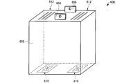
- FIG. 1 is a perspective view schematically showing the electricity storage device according to the present embodiment.
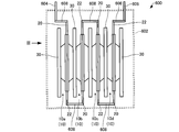
- FIG. 2 is a diagram schematically illustrating the electricity storage device according to the present embodiment.
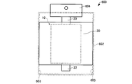
- FIG. 3 is a diagram schematically showing the electricity storage device according to the present embodiment.
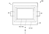
- FIG. 4 is a diagram schematically showing a part of the electricity storage device according to the present embodiment.
- FIG. 5 is a diagram schematically showing a part of the electricity storage device according to the present embodiment.
- FIG. 6 is a diagram schematically showing a part of the electricity storage device according to the present embodiment.
- FIG. 7 is a diagram schematically showing a part of the electricity storage device according to the first modification of the present embodiment.
- FIG. 8 is a diagram schematically showing a part of the electricity storage device according to the first modification of the present embodiment.
- FIG. 1 is a perspective view schematically showing the electricity storage device according to the present embodiment.
- FIG. 2 is a diagram schematically illustrating the electricity storage device according to the present embodiment.
- FIG. 9 is a diagram schematically illustrating a part of the electricity storage device according to the second modification of the present embodiment.
- FIG. 10 is a diagram schematically illustrating a part of the electricity storage device according to the second modification example of the present embodiment.
- FIG. 11 is a diagram schematically illustrating an electricity storage device according to a third modification of the present embodiment.
- FIG. 12 is a diagram schematically illustrating an electricity storage device according to a third modification of the present embodiment.
- FIG. 13 is a diagram schematically illustrating an electricity storage device according to a fourth modification of the present embodiment.
- FIG. 14 is a diagram schematically illustrating an electricity storage device according to a fourth modification of the present embodiment.
- FIG. 15 is a diagram schematically illustrating an electricity storage device according to a fifth modification of the present embodiment.
- FIG. 10 is a diagram schematically illustrating a part of the electricity storage device according to the second modification example of the present embodiment.
- FIG. 11 is a diagram schematically illustrating an electricity storage device according to a
- FIG. 16 is a diagram schematically illustrating an electricity storage device according to a fifth modification example of the present embodiment.
- FIG. 17 is a diagram schematically illustrating a part of the electricity storage device according to the fifth modification example of the present embodiment.
- FIG. 18 is a perspective view schematically showing a part of the electricity storage device according to the fifth modification of the present embodiment.
- FIG. 19 is a diagram schematically illustrating an electricity storage device according to a fifth modification of the present embodiment.
- FIG. 20 is a diagram schematically illustrating an electricity storage device according to a fifth modification of the present embodiment.
- FIG. 21 is a diagram schematically illustrating an electricity storage device according to a sixth modification of the present embodiment.
- FIG. 1 is a perspective view schematically showing an electricity storage device 600 according to the present embodiment.
- FIG. 2 is a diagram schematically showing the electricity storage device 600 according to this embodiment.
- FIG. 3 is a diagram schematically showing the electricity storage device 600 according to the present embodiment, as viewed from the III direction of FIG. 2 and 3 are perspective views of the housing 602 of FIG.
- the power storage device 600 includes a housing 602, a power storage cell 10, a positive electrode terminal 20 and a negative electrode terminal 22 provided in the power storage cell 10, a radiator plate 30, an external terminal 604, and an external terminal 604. 606.
- the electricity storage cell 10 and the heat sink 30 are accommodated in the housing 602.
- the number of power storage cells 10 and heat dissipation plates 30 is not particularly limited, but in the example illustrated in FIG. 2, four power storage cells 10 and five heat dissipation plates 30 are provided.
- the storage cells 10 and the heat dissipation plates 30 are alternately stacked. More specifically, the power storage cell 10a, the power storage cell 10b, the power storage cell 10c, and the power storage cell 10d are provided in this order, and the heat dissipation plate 30 is disposed so as to sandwich each power storage cell.
- the plurality of power storage cells 10 are connected in series.
- the power storage device 600 can increase the output voltage. More specifically, the negative electrode terminal 22 of the energy storage cell 10a and the positive electrode terminal 20 of the energy storage cell 10b are electrically connected, and the negative electrode terminal 22 of the energy storage cell 10b and the positive electrode terminal 20 of the energy storage cell 10c are Electrically connected, the negative electrode terminal 22 of the electricity storage cell 10c and the positive electrode terminal 20 of the electricity storage cell 10d are electrically connected.
- the electrical connection between the positive electrode terminal 20 and the negative electrode terminal 22 is performed by, for example, a conductive wiring 608.
- the plurality of power storage cells 10 may be connected in parallel. The output current can be increased by connecting them in parallel.
- four power storage cells 10 are provided, but the number thereof is not particularly limited.
- one power storage cell 10 may be provided, and four or more power storage cells may be provided. 10 may be provided, and the number can be set in a timely manner according to the target output voltage or output current.
- the shape of the housing 602 is not particularly limited as long as the storage cell 10, the terminals 20 and 22, and the heat sink 30 can be accommodated therein.
- the housing 602 is a quadrangular prism (a rectangular parallelepiped). is there.
- An example of the material of the housing 602 is aluminum.
- An air cooling unit 610 and an exhaust unit 612 may be formed in the housing 602.
- the air cooling unit 610 is formed on the bottom surface (lower surface) of the housing 602
- the exhaust unit 612 is formed on the upper surface (surface facing the bottom surface) of the housing 602. It is desirable that the air cooling unit 610 be disposed so that all of the plurality of heat sinks 30 can be cooled.
- two air-cooling units 610 and two exhaust units 612 are formed, but the numbers are not particularly limited. More specifically, the air cooling unit 610 is a fan for sending air to the heat sink 30 or a heat sink (not shown) thermally connected to the heat sink 30, and the exhaust unit 612 is outside the housing 602. It is a through-hole for exhausting air. Thereby, the heat sink thermally connected to the heat sink 30 or the heat sink 30 can be cooled, and the heat dissipation can be improved.
- External terminals 604 and 606 are provided so as to extend from the inside to the outside of the housing 602.
- the external terminal 604 is electrically connected to the positive electrode terminal 20 of the storage cell 10 a through a wiring 608.
- the external terminal 606 is electrically connected to the negative electrode terminal 22 of the storage cell 10d through a wiring 608.
- Examples of the material of the external terminals 604 and 606 include aluminum, copper, and nickel.
- the heat sink 30 is in contact with the inner surface (side surface) 603 of the housing 602 as shown in FIG.
- the heat dissipation plate 30 is in contact with the two inner surfaces 603 of the housing 602.
- the heat generated in the storage cell 10 can be transmitted to the housing 602 via the heat radiating plate 30 and radiated from the housing 602.
- the heat dissipation can be further improved by cooling the housing 602.
- the heat sink 30 can also function as a heat pipe for conducting heat generated by the power storage cell 10 (power storage unit 18) to the housing 602. Therefore, the electricity storage device 600 can have high heat dissipation.
- FIG. 4 is a plan view schematically showing a part of the electricity storage device 600 according to the present embodiment.
- FIG. 5 is a diagram schematically showing a part of the electricity storage device 600 according to this embodiment, and is a diagram seen from the V direction in FIG. 4. 4 and 5 show, for convenience, one storage cell 10, a set of positive electrode terminal 20 and negative electrode terminal 22 provided in the storage cell 10, and one heat sink 30 provided in the storage cell 10. , Illustrated.
- the electricity storage cell 10 can have an exterior body 12 and an electricity storage unit 18 as shown in FIGS.
- the exterior body 12 houses a power storage unit 18 therein. It can be said that the power storage unit 18 is hermetically sealed by the exterior body 12.
- the exterior body 12 can have a first exterior film 14 and a second exterior film 16.
- the exterior body 12 may be configured by joining the first exterior film 14 and the second exterior film 16 by, for example, thermocompression bonding.
- the first exterior film 14 can have a flat inner surface 14 a that is an inner surface of the exterior body 12.
- the second exterior film 16 can have a flat inner surface 16 a that is an inner surface of the exterior body 12.
- the flat inner surfaces 14 a and 16 a may be in contact with the power storage unit 18 accommodated in the exterior body 12. It can be said that the flat inner surfaces 14 a and 16 a are surfaces formed by swelling of the exterior body 12 by accommodating the power storage unit 18. That is, the planar shape of the flat inner surfaces 14 a and 16 a may be determined by the swelling of the exterior body 12 by the power storage unit 18.
- the planar shape of the flat inner surfaces 14a, 16a is preferably rectangular, and may be square or rectangular. In the example shown in FIG. 4, the planar shape of the flat inner surfaces 14a and 16a is a rectangle.
- the first exterior film 14 can have an outer surface of the exterior body 12 and a flat outer surface 14b which is a surface opposite to the flat inner surface 14a of the first exterior film 14.
- the second exterior film 16 can have an outer surface of the exterior body 12 and a flat outer surface 16 b that is a surface opposite to the flat inner surface 16 a of the second exterior film 16.
- the planar shapes of the flat outer surfaces 14b and 16b may be the same as the planar shapes of the flat inner surfaces 14a and 16a, respectively. It can be said that the flat outer surfaces 14 b and 16 b are surfaces formed by swelling of the exterior body 12 by accommodating the power storage unit 18.
- the laminate film is composed of, for example, a metal layer and a first resin layer and a second resin layer that sandwich the metal layer.
- the material of the metal layer include aluminum.
- the material of the first resin layer include polyethylene terephthalate (PET), polytetrafluoroethylene (PTFE), and polyamide resin.
- the material of the second resin layer include ethylene vinyl acetate copolymer resin (EVA) or olefin resins such as polyethylene and polypropylene.
- the film-shaped exterior films 14 and 16 for example, compared with the case where the hard exterior body (metal can etc.) which consists of metals etc. is used, size reduction and weight reduction of the electrical storage cell 10 are achieved. Can do.
- the power storage unit 18 is accommodated in the exterior body 12.
- the power storage unit 18 includes a positive electrode, a negative electrode, and an electrolyte. Further, the power storage unit 18 may include a separator that separates the positive electrode and the negative electrode.
- the positive electrode, the negative electrode, and the separator can have a sheet shape.
- the power storage unit 18 may have a wound structure in which a positive electrode and a negative electrode arranged via a separator are wound.
- the power storage unit 18 may have a stacked structure in which positive electrodes and negative electrodes are alternately stacked via separators. Specific examples of the power storage unit 18 include a lithium ion capacitor, a lithium ion battery, and an electric double layer capacitor. Note that a detailed description of the positive electrode, the negative electrode, the electrolyte, and the separator constituting the power storage unit 18 will be described later.
- the thickness T of the electricity storage cell 10 is preferably 4 mm or more and 20 mm or less.
- the thickness of the storage cell is in the above range, for example, when the storage unit built in the storage cell has a stacked structure, the number of stacked positive and negative electrodes can be increased. Further, when the power storage unit incorporated in the power storage cell has a wound structure, the number of turns of the positive electrode and the negative electrode can be increased. As a result, the configuration of the power storage device having a large energy capacity intended in the present invention is facilitated.
- the heat generated inside the power storage unit due to charging / discharging tends to be accumulated inside the power storage cell, and the efficiency to the outside Heat dissipation becomes difficult.
- the temperature inside the storage cell tends to increase as it leads to gas generation.
- the thickness of the storage cell 10 is increased in order to obtain large energy, it is possible to efficiently dissipate heat by providing the heat sink 30 in contact with the inner surface 603 of the housing 602 as in the present application. .
- a lithium ion capacitor having an energy capacity of 1000 F or more can be secured.
- the heat generated inside the power storage cell 10 is efficiently radiated to the outside by the heat radiating plate 30 and the housing 602. be able to.
- the thickness T of the electricity storage cell 10 is, for example, the thickness of the electricity storage cell 10 in a state of being accommodated in the exterior body 12 when the electricity storage unit 18 has a wound structure. Further, when the power storage unit 18 has a stacked structure, for example, it is the size (length) in the stacking direction of the power storage cells 10 in a state of being accommodated in the exterior body 12. As described above, the power storage unit 18 may be in contact with the flat inner surfaces 14 a and 16 a of the exterior films 14 and 16. Therefore, the thickness T of the electricity storage cell 10 may be the distance between the flat outer surface 14b and the flat outer surface 16b.
- the positive electrode terminal 20 and the negative electrode terminal 22 are provided through the exterior body 12 as shown in FIG.
- the positive electrode terminal 20 and the negative electrode terminal 22 extend from the inside to the outside of the exterior body 12 in a state where the hermeticity of the exterior body 12 is maintained.
- the arrangement of the positive terminal 20 and the negative terminal 22 is not particularly limited. In the example shown in FIGS. 4 and 5, the positive terminal 20 extends from the left end (one end) of the exterior body 12, and the negative terminal 22 is the right end (the other end) of the exterior body 12. It extends from.
- the positive terminal 20 is electrically connected to the positive electrode of the power storage unit 18.
- the negative terminal 22 is electrically connected to the negative electrode of the power storage unit 18. Examples of the material of the positive electrode terminal 20 include aluminum. Examples of the material of the negative electrode terminal 22 include copper and nickel.
- the heat sink 30 is provided on the outer surface of the exterior body 12 as shown in FIG. In the example shown in FIG. 5, the heat sink 30 is provided in contact with the flat outer surface 14b. Although not shown, the heat sink 30 may be provided in contact with the flat outer surface 16b. The heat sink 30 may be provided so as to cover the entire flat outer surface 14b or the flat outer surface 16b. Thereby, heat dissipation can be improved.
- the exterior body 12 is disposed, for example, inside the outer periphery of the heat sink 30. That is, the area of the heat sink 30 is larger than the area of the exterior body 12 in plan view. Thereby, the surface area of the heat sink 30 can be increased, and heat dissipation can be improved.
- the positive electrode terminal 20 and the negative electrode terminal 22 are disposed so as to protrude outward from the outer periphery of the heat dissipation plate 30 in plan view. Thereby, the connection between the terminals 20 and 22 and the external wiring (not shown) can be facilitated, and a current can be easily obtained from the positive terminal 20.
- Examples of the material of the heat sink 30 include aluminum, iron, copper, or an alloy containing any of these metals as a main component from the viewpoint of thermal conductivity. Of these metals, aluminum is particularly preferable from the viewpoint of weight reduction.
- the shape of the heat sink 30 is not particularly limited, in the example shown in FIG. 4 and FIG. Although not shown, the heat dissipation plate 30 may have irregularities on its surface. Thereby, the surface area of the heat sink 30 can be increased, and heat dissipation can be improved.
- the thickness of the heat sink 30 is preferably 10 ⁇ m or more and 300 ⁇ m or less, and more preferably 50 ⁇ m or more and 200 ⁇ m or less.
- the heat dissipation plate 30 can dissipate the heat generated by the power storage unit 18. Moreover, the heat sink 30 can diffuse the heat generated by the power storage unit 18 uniformly throughout the power storage unit 18 and suppress local temperature rise. For example, when the calorific value at the central portion of the power storage unit 18 is larger than the calorific value at the end portion, the heat radiation plate 30 can make the heat generation uniform.
- the method of installing the heat sink 30 on the exterior body 12 is not particularly limited, a method of bonding the surface of the heat sink 30 and the outer surface of the exterior body 12 is used. More specifically, such as heat-fusible resin (ethylene vinyl acetate copolymer resin, olefin resin, etc.) and adhesive (hot melt adhesive, moisture curable adhesive, pressure sensitive adhesive, etc.) A method of bonding using an adhesive having high thermal conductivity can be exemplified. Further, the thermal conductivity can be further improved by mixing an inorganic filler such as boron nitride or an organic filler such as epoxy into the adhesive.
- heat-fusible resin ethylene vinyl acetate copolymer resin, olefin resin, etc.
- adhesive hot melt adhesive, moisture curable adhesive, pressure sensitive adhesive, etc.
- the configuration in which such a bonding agent is interposed between the heat radiating plate 30 and the outer package 12 is also included in the example of the configuration in which the heat radiating plate 30 is provided in contact with the outer surface of the outer package 12.
- the heat radiating plate 30 and the outer package 12 may be heat-welded or may be pressure-bonded by a pressing method. Or you may make the heat sink 30 and the exterior body 12 contact with a suitable jig
- an adhesive agent in order to improve heat dissipation, it is preferable that an adhesive agent does not exist except an adhesive surface, and an adhesive agent exists only in an adhesive surface.
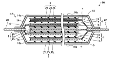
- FIG. 6 is a cross-sectional view showing a part of the electricity storage device 600 according to the present embodiment, and is a cross-sectional view schematically showing the internal structure (of the outer package 12) of the electricity storage cell 10 shown in FIG.
- illustration of the heat sink 30 is abbreviate
- the electrical storage unit 18 has the electrode laminated body 5 and the electrolyte solution (not shown) accommodated in the exterior body 12, as shown in FIG.
- the electrode laminate 5 is immersed in the electrolytic solution.
- the electrode laminate 5 can include a positive electrode 1, a negative electrode 2, and a separator 4.
- the positive electrode 1, the negative electrode 2, and the separator 4 have a sheet shape.
- the electrode laminate 5 is laminated in the order of the negative electrode 2, the positive electrode 1, the negative electrode 2, the positive electrode 1, and the negative electrode 2 from the flat inner surface 16 a of the second exterior film 16, and between the poles and
- the separator 4 is interposed between the pole and the exterior body.
- the positive electrode 1 and the negative electrode 2 are connected in parallel.
- the numbers of the positive electrode 1 and the negative electrode 2 are not particularly limited.
- the form of the electrode laminated body 5 is not limited to the example of illustration,
- stacking a positive electrode, a negative electrode, and a separator may be sufficient. .
- the positive electrode 1 has a positive electrode current collector 1a and a positive electrode active material layer 1b.
- a known material related to an electricity storage device can be used.
- the material of the positive electrode current collector 1a include aluminum, nickel, and titanium.
- the positive electrode current collector 1a may be a porous metal foil made of the aforementioned material.
- the thickness of the positive electrode current collector 1a is not particularly limited, and is, for example, 20 ⁇ m or more and 50 ⁇ m or less.
- the positive electrode current collector 1 a is connected to the positive electrode terminal 20 through the positive electrode lead 6.
- the positive electrode active material layer 1b is formed on the positive electrode current collector 1a.
- the positive electrode active material layer 1b may be formed on both sides of the positive electrode current collector 1a as shown in FIG. 6, or may be formed only on one side.
- the thickness of the positive electrode active material layer 1b is not specifically limited, For example, they are 60 micrometers or more and 90 micrometers or less.
- the positive electrode active material layer 1b is prepared by, for example, dispersing a powdery positive electrode active material, a conductive additive, and a binder (binder) in an aqueous solvent or an organic solvent to prepare a slurry, and collecting the slurry into a positive electrode current collector It is formed by applying to the surface of the body and drying.
- the positive electrode active material is a material that can reversibly support anions such as hexafluorophosphate (PF 6 ⁇ ) and tetrafluoroborate (BF 4 ⁇ ). is there. More specifically, examples of the positive electrode active material include activated carbon and a polyacene-based material (PAS) that is a heat-treated product of an aromatic condensation polymer.
- PES polyacene-based material
- the positive electrode active material is a material capable of reversibly occluding lithium ions. More specifically, examples of the positive electrode active material include lithium nickel oxides, lithium cobalt oxides, lithium manganese oxides, iron phosphate compounds, and mixtures thereof.
- the “lithium-nickel-based oxide” is an oxide having lithium (Li) and nickel (Ni) as constituent metal elements, and the main (first) transition metal element is Ni.
- a composition containing at least one metal element other than Li and Ni that is, at least one of a transition metal element and a typical metal element other than Li and Ni) in a smaller proportion (atomic ratio) than Ni. It is meant to include oxides.
- the metal element include Co, Al, Mn, Cr, Fe, V, Mg, Ti, Zr, Nb, Mo, W, Cu, Zn, Ga, In, Sn, La, and Ce. These metal elements may be used alone or in combination of two or more. The same applies to lithium cobalt oxides and lithium manganese oxides.
- a carbon material such as carbon black (acetylene black or the like), or a metal powder such as nickel powder can be used.
- binder examples include celluloses such as methyl cellulose (MC), carboxymethyl cellulose (CMC), and ethyl cellulose (EC), polyvinyl alcohol, polyacrylate, polyalkylene oxide (for example, polyethylene oxide), polyvinylidene fluoride (PVDF), Fluorine polymers such as polytetrafluoroethylene (PTFE) and polyvinylidene fluoride-hexafluoropropylene copolymer (PVDF-HFP), and organic polymers such as styrene butadiene block copolymer (SBR) can be used.
- celluloses such as methyl cellulose (MC), carboxymethyl cellulose (CMC), and ethyl cellulose (EC)
- polyvinyl alcohol for example, polyethylene oxide
- PVDF polyvinylidene fluoride
- PVDF Fluorine polymers such as polytetrafluoroethylene (PTFE) and polyvinylidene fluoride-hexafluoroprop
- the negative electrode 2 has a negative electrode current collector 2a and a negative electrode active material layer 2b.
- a known material related to an electricity storage device can be used for the negative electrode current collector 2a and the negative electrode active material layer 2b.
- the material of the negative electrode current collector 2a include copper, nickel, and titanium.
- the negative electrode current collector 2a may be a porous metal foil made of the aforementioned material.
- the thickness of the negative electrode collector 2a is not specifically limited, For example, it is 20 micrometers or more and 50 micrometers or less.
- the negative electrode current collector 2 a is connected to the negative electrode terminal 22 through the negative electrode lead 7.
- the negative electrode active material layer 2b is formed on the negative electrode current collector 2a.
- the negative electrode active material layer 2b may be formed on both sides of the negative electrode current collector 2a as shown in FIG. 6, or may be formed only on one side.
- the thickness of the negative electrode active material layer 2b is not specifically limited, For example, they are 60 micrometers or more and 90 micrometers or less.
- the negative electrode active material layer 2b is prepared by, for example, dispersing a powdered negative electrode active material, a conductive additive, and a binder (binder) in an aqueous solvent or an organic solvent to prepare a slurry, It is formed by applying to the surface of the body and drying.
- the negative electrode active material is a material capable of reversibly occluding lithium ions. More specifically, examples of the negative electrode active material include natural graphite, mesocarbon microbead (MCMB) highly oriented graphite (HOPG), hard carbon, and soft carbon.
- MCMB mesocarbon microbead
- HOPG highly oriented graphite
- hard carbon hard carbon
- soft carbon soft carbon
- the negative electrode active material is, for example, a material that can reversibly carry lithium ions. More specifically, examples of the negative electrode active material include activated carbon.
- the materials listed in the description of the positive electrode can be used as the conductive assistant and the binder.
- the separator 4 can be made of a porous material that is durable against an electrolyte, a positive electrode active material, and a negative electrode active material.
- a known material related to the electricity storage device can be used. More specifically, as the separator 4, a nonwoven fabric made of cellulose, rayon, polyethylene, polypropylene, aramid resin, amideimide, polyphenylene sulfide, polyimide, or the like, a porous film, or the like can be used.
- the thickness of the separator 4 is not specifically limited, For example, they are 20 micrometers or more and 50 micrometers or less.
- the separator 4 can isolate the positive electrode 1 and the negative electrode 2 from each other.
- the separator 4 can infiltrate the electrolyte. Note that when the power storage unit 18 uses a solid electrolyte as the electrolyte, the positive electrode 1 and the negative electrode 2 are not short-circuited without using the separator 4, and therefore the separator 4 can be omitted.
- the electrolyte is, for example, a nonaqueous electrolyte.
- the non-aqueous electrolyte may be, for example, a liquid non-aqueous electrolyte containing a non-aqueous organic solvent as a main component, or may be a gel or solid electrolyte.
- propylene carbonate, ethylene carbonate, 1,2-dimethoxyethane, 1,2-diethoxyethane, ⁇ -butyrolactone, tetrahydrofuran, 1,3-dioxolane, dimethyl carbonate, diethyl carbonate, ethyl methyl carbonate, methyl acetate, methyl formate LiPF 6 , LiBF 4 , LiClO 4 , LiCF 3 SO 3 , LiC 4 F 9 SO 3 , LiN (CF) can be added to any solvent selected from non-aqueous organic solvents such as 3 SO 2 ) 2 , LiC (CF 3 SO 2 ) 3 may be used as an electrolyte having a composition in which one or more lithium salts such as 3 salt are dissolved.
- the concentration of the lithium salt in the electrolyte is, for example, 0.5 mol / L or more and 3 mol / L or less.
- the heat sink 30 is in contact with the inner surface 603 of the housing 602.
- the electricity storage device 600 can transmit the heat generated in the electricity storage cell 10 to the housing 602 via the heat dissipation plate 30 and dissipate the heat from the housing 602. Therefore, the electricity storage device 600 can have high heat dissipation.
- the power storage cell 10 is applied particularly effectively when a lithium ion capacitor having a large capacity and a large calorific value due to charge / discharge is used as the power storage cell 10. be able to.
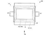
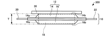
- FIG. 7 is a plan view schematically showing a part of the electricity storage device 300 according to the first modification of the present embodiment.
- FIG. 8 is a diagram schematically showing a part of the electricity storage device 300 according to the first modification of the present embodiment, and is a diagram seen from the VIII direction of FIG. 7 corresponds to FIG. 4, and FIG. 8 corresponds to FIG.
- the exterior body 12 is disposed inside the outer periphery of the heat sink 30 in a plan view, and a part of the heat sink 30 and a part of the terminals 20 and 22 overlap. It was.
- the heat sink 30 and the terminals 20 and 22 do not overlap in plan view as shown in FIG. That is, the heat sink 30 is separated from the terminals 20 and 22 in plan view.
- the electrolyte or the like may be decomposed and gas may be generated. And the internal pressure of an electrical storage cell rises with the gas, and an electrical storage cell may deform
- contact between the heat dissipation plate 30 and the terminals 20 and 22 can be prevented even when the heat dissipation plate 30 is deformed.
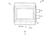
- FIG. 9 is a plan view schematically showing an electricity storage device 400 according to a second modification of the present embodiment.
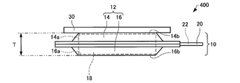
- FIG. 10 is a diagram schematically showing an electricity storage device 400 according to the second modification of the present embodiment, and is a diagram seen from the X direction of FIG. 9 corresponds to FIG. 4, and FIG. 10 corresponds to FIG.
- the positive electrode terminal 20 extends from one end of the outer package 12
- the negative terminal 22 extends from the other end of the outer package 12. It was.
- both the terminals 20 and 22 extend from one end (for example, the right end).
- the heat sink 30 and the terminals 20 and 22 do not need to overlap in plan view as shown in FIG. Thereby, contact with the heat sink 30 and the terminals 20 and 22 can be prevented.
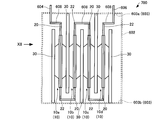
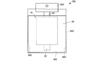
- FIG. 11 is a diagram schematically showing an electricity storage device 700 according to a third modification of the present embodiment, and corresponds to FIG.
- FIG. 12 is a diagram schematically showing an electricity storage device 700 according to a third modification of the present embodiment, and is a diagram seen from the XII direction of FIG.
- the heat radiating plates 30 are alternately in contact with the inner surface 603 (for example, the upper surface or the lower surface) of the housing 602. That is, one of the heat radiating plates 30 that are adjacent to each other via the storage cell 10 is in contact with the first inner surface 603 a (for example, the upper surface) of the housing 602, and the other heat radiating plate 30 is the second heat radiating plate 30 of the housing 602. It is in contact with a second inner surface 603b (for example, the lower surface) different from the first inner surface 603a.
- a second inner surface 603b for example, the lower surface
- the heat sink 30 sandwiched between the power storage cell 10a and the power storage cell 10b, and the heat sink 30 sandwiched between the power storage cell 10c and the power storage cell 10d are in contact with the first inner surface 603a.
- the heat sink 30 sandwiched between the power storage cell 10b and the power storage cell 10c, and the heat sink 30 at both ends are in contact with the second inner surface 603b.
- the heat sink 30 may be in contact with the inner surface (side surface) of the housing 602 as shown in FIG. That is, the heat sink 30 may be in contact with the three inner surfaces 603 of the housing 602. Thereby, heat can be more uniformly conducted to the housing 602.
- the heat sink 30 may be connected to a cooling mechanism such as a chiller unit. Also with such a form, the heat dissipation of the electrical storage device 700 can be improved.
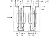
- FIG. 13 is a diagram schematically showing an electricity storage device 800 according to a fourth modification of the present embodiment, and corresponds to FIG.
- FIG. 14 is a diagram schematically showing an electricity storage device 800 according to the fourth modification of the present embodiment, and is a diagram seen from the XIV direction of FIG.
- a power storage cell 10a, a power storage cell 10b, a power storage cell 10c, and a power storage cell 10d are provided in this order, and the heat dissipation plate 30 is arranged so as to sandwich each power storage cell. It was.
- the electrical storage device 800 as shown in FIG. 13, the heat sink 30 is provided only between the electrical storage cell 10a and the electrical storage cell 10b and between the electrical storage cell 10c and the electrical storage cell 10d.
- the electricity storage cell 10b and the electricity storage cell 10c are provided apart from each other through a gap.
- the electricity storage device 800 for example, when gas is generated in the electricity storage cell 10 as compared with the example of the electricity storage device 600, the electricity storage cell 10 is easily deformed because there is a gap between the electricity storage cells 10 ( Can swell). Therefore, the power storage device 800 can have high reliability. If the electricity storage cell cannot be deformed despite the generation of gas in the electricity storage cell, the internal pressure of the electricity storage cell is greatly increased, and a problem may occur.
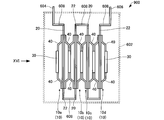
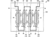
- FIG. 15 is a diagram schematically showing an electricity storage device 900 according to a fifth modification of the present embodiment, and corresponds to FIG.
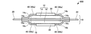
- FIG. 16 is a diagram schematically showing an electricity storage device 900 according to a fifth modification of the present embodiment, and is a diagram seen from the XVI direction of FIG.
- FIG. 17 is a diagram schematically illustrating a part of an electricity storage device 900 according to a fifth modification of the present embodiment.
- FIG. 18 is a perspective view schematically showing a part of an electricity storage device 900 according to an eighth modification of the present embodiment.
- FIG. 15 is a diagram schematically showing an electricity storage device 900 according to a fifth modification of the present embodiment, and corresponds to FIG.
- FIG. 16 is a diagram schematically showing an electricity storage device 900 according to a fifth modification of the present embodiment, and is a diagram seen from the XVI direction of FIG.
- FIG. 17 is a diagram schematically illustrating a part of an electricity storage device 900 according to a fifth modification of the
- the electricity storage device 900 has a fixing member 40 as shown in FIGS.
- the fixing member 40 is provided on the outer surface of the exterior body 12, for example, avoiding the heat sink 30. That is, the fixing member 40 and the heat sink 30 do not overlap.
- the heat sink 30 is provided in the center part of the flat outer surfaces 14b and 16b.
- the fixing member 40 is provided from the flat outer surface 14b to the inclined outer surface 14c that is continuous with the flat outer surface 14b and is inclined with respect to the flat outer surface 14b, avoiding the central portion of the flat outer surface 14b.
- the fixing member 40 is provided from the flat outer surface 16b to the inclined outer surface 16c that is continuous with the flat outer surface 16b and is inclined with respect to the flat outer surface 16b, avoiding the central portion of the flat outer surface 16b.
- four fixing members 40 are provided for one storage cell 10.
- the storage cell includes a fixing member 40 (first fixing member 40a) on the first exterior film 14 side and a fixing member 40 (second fixing member 40b) on the second exterior film 16 side.
- the storage cell 10 can be fixed in the housing 602 with the 10 interposed therebetween.
- the first fixing member 40 a is provided from the flat outer surface 14 b to the inclined outer surface 14 c of the first exterior film 14.
- the second fixing member 40b is provided from the flat outer surface 16b to the inclined outer surface 16c of the second exterior film 16.
- the fixing member 40 can have a bulge portion 42.
- the electrical storage cell 10 can be fixed stably.
- a heat-fusible resin ethylene vinyl acetate copolymer resin, olefin resin, etc.
- an adhesive hot melt adhesive, moisture curable adhesive, pressure sensitive
- a method of bonding using an adhesive having a high thermal conductivity such as an adhesive can be exemplified.
- an inorganic filler such as boron nitride or an organic filler such as epoxy may be mixed into the adhesive.
- the fixing member 40 is connected to the inner surface 603 of the housing 602 and can fix the storage cell 10 in the housing 602.
- a material of the fixing member 40 for example, aluminum, iron, copper, or an alloy mainly containing any one of these metals can be given.
- a method for connecting the fixing member 40 and the housing 602 is not particularly limited.
- the screw hole 44 (see FIG. 18) of the fixing member 40 is fixed to the inner surface 603 of the housing 602 with a screw. It may be fixed by welding, or may be performed using the adhesives listed as the installation method of the fixing member 40 and the exterior body 12.
- the rigidity of the fixing member 40 may be larger than the rigidity of the heat sink 30. Thereby, the electrical storage cell 10 can be stably fixed.
- the rigidity of the fixing member 40 can be made larger than the rigidity of the heat sink 30 by making the thickness of the fixing member 40 larger than the thickness of the heat sink 30.
- the adjacent heat storage cells 10 share one heat sink 30.
- two heat sinks 30 are provided in one power storage cell 10. Yes.
- four power storage cells 10 are provided, but the number is not particularly limited.
- one power storage cell 10 may be provided, and four or more power storage cells 10 may be provided.
- the number of storage cells 10 may be provided, and the number can be set in a timely manner according to the target output voltage or output current.
- the electricity storage cell 10 can be stably fixed in the housing 602 by the fixing member 40. Therefore, the power storage device 900 can have high reliability.
- the rigidity of the fixing member 40 can be made larger than the rigidity of the heat sink 30 by making the thickness of the fixing member 40 larger than the thickness of the heat sink 30.
- the heat storage cell 10 can be stably fixed while having high heat dissipation.
- the fixing member 40 and the heat radiating plate 30 do not overlap, the fixing member 40 does not prevent the heat radiating plate 30 from being deformed. 10 deformations can be followed.
- rigidity refers to the degree to which an object resists deformation when an external force is applied to the object to cause deformation. That is, the smaller the rigidity, the easier the object is to deform (bend easily).
- the power storage device 900 may include a heat sink 30 between the fixing member 40 and the power storage cell 10. That is, a part of the fixing member 40 and a part of the heat radiating plate 30 may overlap each other. Thereby, it can suppress more reliably that a heat sink peels from an electrical storage cell.
- FIG. 21 is a diagram schematically showing an electricity storage device 1000 according to the sixth modification example of the present embodiment, and corresponds to FIG.
- the power storage device 1000 according to the sixth modification example of the present embodiment will be described mainly regarding differences from the power storage device 900 according to the fifth modification example of the present embodiment.
- the electricity storage device 900 four fixing members 40 are provided for one electricity storage cell 10 as shown in FIG.
- two fixing members 40 are provided for one electricity storage cell 10. More specifically, two power storage cells 10 are provided with the heat dissipation plate 30 interposed therebetween, and further two fixing members 40 are provided with the power storage cell 10 interposed therebetween.
- the electricity storage cell 10 when the gas is generated in the electricity storage cell 10 as compared with the example of the electricity storage device 900, the electricity storage cell 10 can be easily deformed (expanded). If the electricity storage cell cannot be deformed despite the generation of gas in the electricity storage cell, the internal pressure of the electricity storage cell is greatly increased, and a problem may occur.
- the present invention is not limited to the above-described embodiment, and various modifications can be made. For example, it is possible to appropriately combine each embodiment and each modification. Further, for example, the present invention includes substantially the same configuration (for example, a configuration having the same function, method and result, or a configuration having the same purpose and effect) as the configuration described in the embodiment. In addition, the invention includes a configuration in which a non-essential part of the configuration described in the embodiment is replaced. In addition, the present invention includes a configuration that achieves the same effect as the configuration described in the embodiment or a configuration that can achieve the same object. In addition, the invention includes a configuration in which a known technique is added to the configuration described in the embodiment.
Landscapes
- Engineering & Computer Science (AREA)
- Power Engineering (AREA)
- Microelectronics & Electronic Packaging (AREA)
- Chemical & Material Sciences (AREA)
- Manufacturing & Machinery (AREA)
- Chemical Kinetics & Catalysis (AREA)
- Electrochemistry (AREA)
- General Chemical & Material Sciences (AREA)
- Materials Engineering (AREA)
- Secondary Cells (AREA)
- Battery Mounting, Suspending (AREA)
- Electric Double-Layer Capacitors Or The Like (AREA)
- Sealing Battery Cases Or Jackets (AREA)
Abstract
Description
本発明にかかる蓄電デバイスの一態様は、
正極、負極、および電解質を有する蓄電ユニットが、外装体に収容された蓄電セルと、
前記蓄電セルの前記外装体の外表面に設けられた放熱板と、
前記蓄電セルおよび前記放熱板を収容する筐体と、
を含み、
前記放熱板は、前記筐体の内面に接している。
適用例1において、
前記蓄電セルと前記放熱板とは、複数積層され、
複数の前記蓄電セルは、電気的に接続されていることができる。
適用例2において、
前記蓄電セルと前記放熱板とは、交互に積層され、
前記蓄電セルを介して隣り合う前記放熱板のうち、
一方の前記放熱板は、前記筐体の第1内面に接し、
他方の前記放熱板は、前記筐体の前記第1内面とは異なる第2内面に接していることができる。
適用例2において、
複数の前記蓄電セルのうち、第1蓄電セル、第2蓄電セル、第3蓄電セル、および第4蓄電セルは、この順で積層され、
前記第1蓄電セルと前記第2蓄電セルとの間、および前記第3蓄電セルと前記第4蓄電セルとの間に、前記放熱板が配置され、
前記第2蓄電セルおよび前記第3蓄電セルは、空隙を介して、互いに離間していることができる。
適用例1ないし4のいずれか1例において、
前記筐体の内面に接続された第1固定部材および第2固定部材を、さらに含み、
前記蓄電セルは、前記第1固定部材と前記第2固定部材とに挟まれて、固定されていることができる。
適用例5において、
前記外装体は、第1外装フィルムと第2外装フィルムとを接合することにより構成され、
前記第1外装フィルムおよび前記第2外装フィルムは、
前記蓄電ユニットを前記外装体に収容することによるふくらみによって形成される扁平外面と、
前記扁平外面と連続し前記扁平外面に対して傾斜した傾斜外面と、
を有し、
前記第1固定部材は、前記第1外装フィルムの、前記扁平外面から前記傾斜外面まで設けられ、
前記第2固定部材は、前記第2外装フィルムの、前記扁平外面から前記傾斜外面まで設けられていることができる。
適用例6において、
前記放熱板は、前記第1外装フィルムの前記扁平外面、および前記第2外装フィルムの前記扁平外面に設けられ、
前記第1固定部材と、前記第1外装フィルムの前記扁平外面に設けられた前記放熱板とは、重なっておらず、
前記第2固定部材と、前記第2外装フィルムの前記扁平外面に設けられた前記放熱板とは、重なっていないことができる。
適用例6において、
前記放熱板は、前記第1外装フィルムの前記扁平外面、および前記第2外装フィルムの前記扁平外面に設けられ、
前記第1固定部材と、前記第1外装フィルムの前記扁平外面に設けられた前記放熱板とは、重なっており、
前記第2固定部材と、前記第2外装フィルムの前記扁平外面に設けられた前記放熱板とは、重なっていることができる。
適用例5ないし8のいずれか1例において、
前記第1固定部材の厚みおよび前記第2固定部材の厚みは、前記放熱板の厚みよりも大きいことができる。
適用例1ないし9のいずれか1例において、
前記筐体の材質は、アルミニウムであることができる。
適用例1ないし10のいずれか1例において、
前記外装体に設けられ、前記正極と電気的に接続された正極端子と、
前記外装体に設けられ、前記負極と電気的に接続された負極端子と、
を、さらに含み、
前記放熱板は、前記正極端子および前記負極端子と重なっていないことができる。
適用例1ないし11のいずれか1例において、
前記蓄電ユニットは、リチウムイオンキャパシタであることができる。
まず、本実施形態に係る蓄電デバイスについて説明する。図1は、本実施形態に係る蓄電デバイス600を模式的に示す斜視図である。図2は、本実施形態に係る蓄電デバイス600を模式的に示す図である。図3は、本実施形態に係る蓄電デバイス600を模式的に示す図であって、図2のIII方向から見た図である。なお、図2,3は、図1の筐体602を透視して見た図である。
次に、本実施形態の変形例に係る蓄電デバイスについて、図面を参照しながら説明する。以下、本実施形態の変形例に係る蓄電デバイスにおいて、本実施形態に係る蓄電デバイス600の構成部材と同様の機能を有する部材については同一の符号を付し、その詳細な説明を省略する。
まず、本実施形態の第1変形例に係る蓄電デバイスについて、図面を参照しながら説明する。図7は、本実施形態の第1変形例に係る蓄電デバイス300の一部を模式的に示す平面図である。図8は、本実施形態の第1変形例に係る蓄電デバイス300の一部を模式的に示す図であって、図7のVIII方向から見た図である。なお、図7は、図4に対応し、図8は、図5に対応している。
次に、本実施形態の第2変形例に係る蓄電デバイスについて、図面を参照しながら説明する。図9は、本実施形態の第2変形例に係る蓄電デバイス400を模式的に示す平面図である。図10は、本実施形態の第2変形例に係る蓄電デバイス400を模式的に示す図であって、図9のX方向から見た図である。なお、図9は、図4に対応し、図10は、図5に対応している。
次に、本実施形態の第3変形例に係る蓄電デバイスについて、図面を参照しながら説明する。図11は、本実施形態の第3変形例に係る蓄電デバイス700を模式的に示す図であって、図2に対応するものである。図12は、本実施形態の第3変形例に係る蓄電デバイス700を模式的に示す図であって、図11のXII方向から見た図である。
次に、本実施形態の第4変形例に係る蓄電デバイスについて、図面を参照しながら説明する。図13は、本実施形態の第4変形例に係る蓄電デバイス800を模式的に示す図であって、図2に対応するものである。図14は、本実施形態の第4変形例に係る蓄電デバイス800を模式的に示す図であって、図13のXIV方向から見た図である。
次に、本実施形態の第5変形例に係る蓄電デバイスについて、図面を参照しながら説明する。図15は、本実施形態の第5変形例に係る蓄電デバイス900を模式的に示す図であって、図2に対応するものである。図16は、本実施形態の第5変形例に係る蓄電デバイス900を模試的に示す図であって、図15のXVI方向から見た図である。図17は、本実施形態の第5変形例に係る蓄電デバイス900の一部を模式的に示す図である。図18は、本実施形態の第8変形例に係る蓄電デバイス900の一部を模式的に示す斜視図である。なお、図17では、便宜上、1つの蓄電セル10、該蓄電セル10に設けられた端子20,22、該蓄電セル10に設けられた放熱板30、および該蓄電セル10に設けられた固定部材40のみを図示している。また、図18では、便宜上、1つの蓄電セル10、該蓄電セル10に設けられた端子20,22、および該蓄電セル10に設けられた固定部材40のみを図示している。
次に、本実施形態の第6変形例に係る蓄電デバイスについて、図面を参照しながら説明する。図21は、本実施形態の第6変形例に係る蓄電デバイス1000を模式的に示す図であって、図15に対応するものである。以下、本実施形態の第6変形例に係る蓄電デバイス1000について、主に、本実施形態の第5変形例に係る蓄電デバイス900との相違点について説明する。
Claims (12)
- 正極、負極、および電解質を有する蓄電ユニットが、外装体に収容された蓄電セルと、
前記蓄電セルの前記外装体の外表面に設けられた放熱板と、
前記蓄電セルおよび前記放熱板を収容する筐体と、
を含み、
前記放熱板は、前記筐体の内面に接している、蓄電デバイス。 - 請求項1において、
前記蓄電セルと前記放熱板とは、複数積層され、
複数の前記蓄電セルは、電気的に接続されている、蓄電デバイス。 - 請求項2において、
前記蓄電セルと前記放熱板とは、交互に積層され、
前記蓄電セルを介して隣り合う前記放熱板のうち、
一方の前記放熱板は、前記筐体の第1内面に接し、
他方の前記放熱板は、前記筐体の前記第1内面とは異なる第2内面に接している、蓄電デバイス。 - 請求項2において、
複数の前記蓄電セルのうち、第1蓄電セル、第2蓄電セル、第3蓄電セル、および第4蓄電セルは、この順で積層され、
前記第1蓄電セルと前記第2蓄電セルとの間、および前記第3蓄電セルと前記第4蓄電セルとの間に、前記放熱板が配置され、
前記第2蓄電セルおよび前記第3蓄電セルは、空隙を介して、互いに離間している、蓄電デバイス。 - 請求項1ないし4のいずれか1項において、
前記筐体の内面に接続された第1固定部材および第2固定部材を、さらに含み、
前記蓄電セルは、前記第1固定部材と前記第2固定部材とに挟まれて、固定されている、蓄電デバイス。 - 請求項5において、
前記外装体は、第1外装フィルムと第2外装フィルムとを接合することにより構成され、
前記第1外装フィルムおよび前記第2外装フィルムは、
前記蓄電ユニットを前記外装体に収容することによるふくらみによって形成される扁平外面と、
前記扁平外面と連続し前記扁平外面に対して傾斜した傾斜外面と、
を有し、
前記第1固定部材は、前記第1外装フィルムの、前記扁平外面から前記傾斜外面まで設けられ、
前記第2固定部材は、前記第2外装フィルムの、前記扁平外面から前記傾斜外面まで設けられている、蓄電デバイス。 - 請求項6において、
前記放熱板は、前記第1外装フィルムの前記扁平外面、および前記第2外装フィルムの前記扁平外面に設けられ、
前記第1固定部材と、前記第1外装フィルムの前記扁平外面に設けられた前記放熱板とは、重なっておらず、
前記第2固定部材と、前記第2外装フィルムの前記扁平外面に設けられた前記放熱板とは、重なっていない、蓄電デバイス。 - 請求項6において、
前記放熱板は、前記第1外装フィルムの前記扁平外面、および前記第2外装フィルムの前記扁平外面に設けられ、
前記第1固定部材と、前記第1外装フィルムの前記扁平外面に設けられた前記放熱板とは、重なっており、
前記第2固定部材と、前記第2外装フィルムの前記扁平外面に設けられた前記放熱板とは、重なっている、蓄電デバイス。 - 請求項5ないし8のいずれか1項において、
前記第1固定部材の厚みおよび前記第2固定部材の厚みは、前記放熱板の厚みよりも大きい、蓄電デバイス。 - 請求項1ないし9のいずれか1項において、
前記筐体の材質は、アルミニウムである、蓄電デバイス。 - 請求項1ないし10のいずれか1項において、
前記外装体に設けられ、前記正極と電気的に接続された正極端子と、
前記外装体に設けられ、前記負極と電気的に接続された負極端子と、
を、さらに含み、
前記放熱板は、前記正極端子および前記負極端子と重なっていない、蓄電デバイス。 - 請求項1ないし11のいずれか1項において、
前記蓄電ユニットは、リチウムイオンキャパシタである、蓄電デバイス。
Priority Applications (2)
| Application Number | Priority Date | Filing Date | Title |
|---|---|---|---|
| JP2012509423A JP5534264B2 (ja) | 2010-04-08 | 2011-03-24 | 蓄電デバイス |
| CN2011900003936U CN202839892U (zh) | 2010-04-08 | 2011-03-24 | 蓄电设备 |
Applications Claiming Priority (2)
| Application Number | Priority Date | Filing Date | Title |
|---|---|---|---|
| JP2010089452 | 2010-04-08 | ||
| JP2010-089452 | 2010-04-08 |
Publications (1)
| Publication Number | Publication Date |
|---|---|
| WO2011125505A1 true WO2011125505A1 (ja) | 2011-10-13 |
Family
ID=44762459
Family Applications (1)
| Application Number | Title | Priority Date | Filing Date |
|---|---|---|---|
| PCT/JP2011/057087 Ceased WO2011125505A1 (ja) | 2010-04-08 | 2011-03-24 | 蓄電デバイス |
Country Status (4)
| Country | Link |
|---|---|
| JP (1) | JP5534264B2 (ja) |
| CN (1) | CN202839892U (ja) |
| TW (1) | TWI504041B (ja) |
| WO (1) | WO2011125505A1 (ja) |
Cited By (15)
| Publication number | Priority date | Publication date | Assignee | Title |
|---|---|---|---|---|
| WO2014010395A1 (ja) * | 2012-07-13 | 2014-01-16 | 日産自動車株式会社 | 電池構造体 |
| JP2015002264A (ja) * | 2013-06-14 | 2015-01-05 | 旭化成Fdkエナジーデバイス株式会社 | 蓄電モジュール |
| WO2016148225A1 (ja) * | 2015-03-19 | 2016-09-22 | 株式会社オートネットワーク技術研究所 | 冷却部材、及び蓄電モジュール |
| JP2016178078A (ja) * | 2015-03-19 | 2016-10-06 | 株式会社オートネットワーク技術研究所 | 冷却部材、及び蓄電モジュール |
| US9576746B2 (en) | 2011-04-25 | 2017-02-21 | Jm Energy Corporation | Energy storage module including conductive member secured on bus bar and in contact with pad of wiring board |
| JP2017068986A (ja) * | 2015-09-29 | 2017-04-06 | パナソニックIpマネジメント株式会社 | 電池モジュール |
| CN106684497A (zh) * | 2016-12-30 | 2017-05-17 | 中国电子科技集团公司第十八研究所 | 一种自冷却电池 |
| JP2017147048A (ja) * | 2016-02-15 | 2017-08-24 | Fdk株式会社 | 蓄電モジュール |
| JP2019029632A (ja) * | 2017-07-26 | 2019-02-21 | 旭化成株式会社 | 非水系リチウム蓄電素子を有する蓄電モジュール |
| CN111180622A (zh) * | 2018-11-12 | 2020-05-19 | 丰田自动车株式会社 | 电池组 |
| JP2020080214A (ja) * | 2018-11-12 | 2020-05-28 | 株式会社イノアックコーポレーション | 組電池用緩衝材 |
| CN113161676A (zh) * | 2021-04-26 | 2021-07-23 | 恩拓必(临沂)能源发展有限责任公司 | 一种新能源汽车用电池散热系统及其方法 |
| JP2022538171A (ja) * | 2019-06-25 | 2022-08-31 | インフェノクス ゲーエムベーハー | 挿入モジュールを収容及び冷却するための収容装置 |
| JP7197736B1 (ja) | 2022-02-18 | 2022-12-27 | Apb株式会社 | 電池モジュール |
| JP2024506457A (ja) * | 2022-01-11 | 2024-02-14 | エルジー エナジー ソリューション リミテッド | 安全性が向上したパウチ型電池セル及びこれを含む電池モジュール |
Families Citing this family (1)
| Publication number | Priority date | Publication date | Assignee | Title |
|---|---|---|---|---|
| JP6598026B2 (ja) * | 2016-08-03 | 2019-10-30 | 株式会社オートネットワーク技術研究所 | 蓄電モジュール |
Citations (3)
| Publication number | Priority date | Publication date | Assignee | Title |
|---|---|---|---|---|
| JP2006245414A (ja) * | 2005-03-04 | 2006-09-14 | Japan Radio Co Ltd | 電気二重層キャパシタ装置 |
| JP2010010460A (ja) * | 2008-06-27 | 2010-01-14 | Fdk Corp | 蓄電装置 |
| JP2010010381A (ja) * | 2008-06-26 | 2010-01-14 | Fdk Corp | 蓄電ユニット及びその製造方法 |
Family Cites Families (6)
| Publication number | Priority date | Publication date | Assignee | Title |
|---|---|---|---|---|
| JP2003133188A (ja) * | 2001-10-29 | 2003-05-09 | Nissan Diesel Motor Co Ltd | 電気二重層キャパシタ |
| TW544963B (en) * | 2002-05-15 | 2003-08-01 | Handsun Electronic Entpr Co Lt | Battery module assembling structure |
| KR100904373B1 (ko) * | 2004-12-24 | 2009-06-25 | 주식회사 엘지화학 | 이차전지 모듈용 방열 구조물, 및 그것을 포함하는 스위칭보드 및 이차전지 모듈 |
| KR100877816B1 (ko) * | 2005-01-21 | 2009-01-12 | 주식회사 엘지화학 | 안전성이 향상된 전지팩 |
| JP5354846B2 (ja) * | 2006-08-11 | 2013-11-27 | 株式会社東芝 | 組電池および組電池の充放電方法 |
| JP3984276B1 (ja) * | 2006-09-28 | 2007-10-03 | 株式会社パワーシステム | 蓄電装置 |
-
2011
- 2011-03-24 WO PCT/JP2011/057087 patent/WO2011125505A1/ja not_active Ceased
- 2011-03-24 JP JP2012509423A patent/JP5534264B2/ja not_active Expired - Fee Related
- 2011-03-24 CN CN2011900003936U patent/CN202839892U/zh not_active Expired - Lifetime
- 2011-04-07 TW TW100112032A patent/TWI504041B/zh not_active IP Right Cessation
Patent Citations (3)
| Publication number | Priority date | Publication date | Assignee | Title |
|---|---|---|---|---|
| JP2006245414A (ja) * | 2005-03-04 | 2006-09-14 | Japan Radio Co Ltd | 電気二重層キャパシタ装置 |
| JP2010010381A (ja) * | 2008-06-26 | 2010-01-14 | Fdk Corp | 蓄電ユニット及びその製造方法 |
| JP2010010460A (ja) * | 2008-06-27 | 2010-01-14 | Fdk Corp | 蓄電装置 |
Cited By (21)
| Publication number | Priority date | Publication date | Assignee | Title |
|---|---|---|---|---|
| US9576746B2 (en) | 2011-04-25 | 2017-02-21 | Jm Energy Corporation | Energy storage module including conductive member secured on bus bar and in contact with pad of wiring board |
| WO2014010395A1 (ja) * | 2012-07-13 | 2014-01-16 | 日産自動車株式会社 | 電池構造体 |
| JP2015002264A (ja) * | 2013-06-14 | 2015-01-05 | 旭化成Fdkエナジーデバイス株式会社 | 蓄電モジュール |
| WO2016148225A1 (ja) * | 2015-03-19 | 2016-09-22 | 株式会社オートネットワーク技術研究所 | 冷却部材、及び蓄電モジュール |
| JP2016178078A (ja) * | 2015-03-19 | 2016-10-06 | 株式会社オートネットワーク技術研究所 | 冷却部材、及び蓄電モジュール |
| JP2017068986A (ja) * | 2015-09-29 | 2017-04-06 | パナソニックIpマネジメント株式会社 | 電池モジュール |
| JP2017147048A (ja) * | 2016-02-15 | 2017-08-24 | Fdk株式会社 | 蓄電モジュール |
| CN106684497A (zh) * | 2016-12-30 | 2017-05-17 | 中国电子科技集团公司第十八研究所 | 一种自冷却电池 |
| JP2019029632A (ja) * | 2017-07-26 | 2019-02-21 | 旭化成株式会社 | 非水系リチウム蓄電素子を有する蓄電モジュール |
| JP2020080214A (ja) * | 2018-11-12 | 2020-05-28 | 株式会社イノアックコーポレーション | 組電池用緩衝材 |
| CN111180622A (zh) * | 2018-11-12 | 2020-05-19 | 丰田自动车株式会社 | 电池组 |
| JP2020080219A (ja) * | 2018-11-12 | 2020-05-28 | トヨタ自動車株式会社 | 組電池 |
| JP7161673B2 (ja) | 2018-11-12 | 2022-10-27 | トヨタ自動車株式会社 | 組電池 |
| JP2022538171A (ja) * | 2019-06-25 | 2022-08-31 | インフェノクス ゲーエムベーハー | 挿入モジュールを収容及び冷却するための収容装置 |
| JP7352663B2 (ja) | 2019-06-25 | 2023-09-28 | インフェノクス ゲーエムベーハー | 挿入モジュールを収容及び冷却するための収容装置 |
| CN113161676A (zh) * | 2021-04-26 | 2021-07-23 | 恩拓必(临沂)能源发展有限责任公司 | 一种新能源汽车用电池散热系统及其方法 |
| CN113161676B (zh) * | 2021-04-26 | 2022-06-28 | 恩拓必(临沂)能源发展有限责任公司 | 一种新能源汽车用电池散热系统及其方法 |
| JP2024506457A (ja) * | 2022-01-11 | 2024-02-14 | エルジー エナジー ソリューション リミテッド | 安全性が向上したパウチ型電池セル及びこれを含む電池モジュール |
| JP7683895B2 (ja) | 2022-01-11 | 2025-05-27 | エルジー エナジー ソリューション リミテッド | 安全性が向上したパウチ型電池セル及びこれを含む電池モジュール |
| JP7197736B1 (ja) | 2022-02-18 | 2022-12-27 | Apb株式会社 | 電池モジュール |
| JP2023121006A (ja) * | 2022-02-18 | 2023-08-30 | Apb株式会社 | 電池モジュール |
Also Published As
| Publication number | Publication date |
|---|---|
| TW201212337A (en) | 2012-03-16 |
| CN202839892U (zh) | 2013-03-27 |
| TWI504041B (zh) | 2015-10-11 |
| JP5534264B2 (ja) | 2014-06-25 |
| JPWO2011125505A1 (ja) | 2013-07-08 |
Similar Documents
| Publication | Publication Date | Title |
|---|---|---|
| JP5534264B2 (ja) | 蓄電デバイス | |
| JP4173674B2 (ja) | 電気化学デバイスモジュール | |
| US9887404B2 (en) | Secondary battery | |
| JP5520017B2 (ja) | ラミネートフィルム外装体を有する蓄電素子 | |
| US20120100413A1 (en) | Secondary battery and assembled battery | |
| CN115461909B (zh) | 一种电化学装置及包含该电化学装置的电子装置 | |
| JP4135474B2 (ja) | ラミネート二次電池、複数のラミネート二次電池からなる組電池モジュール、複数の組電池モジュールからなる組電池ならびにこれらいずれかの電池を搭載した電気自動車 | |
| JP3972411B2 (ja) | リチウム電池 | |
| JP2011070932A (ja) | リチウム二次電池 | |
| JP2004178914A (ja) | バイポーラ電極およびその電極を用いたバイポーラ二次電池 | |
| JP2005317468A (ja) | バイポーラ電極、バイポーラ電極の製造方法、バイポーラ電池、組電池、およびこれらを搭載した車両 | |
| JP2004171954A (ja) | ラミネート二次電池、複数のラミネート二次電池からなる組電池モジュール、複数の組電池モジュールからなる組電池ならびにこれらいずれかの電池を搭載した電気自動車 | |
| JP5214364B2 (ja) | リチウムイオン二次電池 | |
| JP2017059538A (ja) | 積層型電池 | |
| JP7130920B2 (ja) | 非水電解液二次電池、非水電解液二次電池の設計方法及び非水電解液二次電池の製造方法 | |
| JP5509561B2 (ja) | 非水電解質二次電池 | |
| WO2014068740A1 (ja) | 電池ユニット | |
| CN111697261A (zh) | 锂二次电池 | |
| CN110692156B (zh) | 密闭式电池、电池组以及发动机启动用电池 | |
| WO2023106214A1 (ja) | 電解液、二次電池および半固体電池 | |
| JP5776948B2 (ja) | リチウム二次電池およびその製造方法 | |
| WO2022168835A1 (ja) | 電気化学セル | |
| JP4586656B2 (ja) | フィルム外装型リチウム電池 | |
| CN108695557B (zh) | 非水电解液二次电池 | |
| WO2022051879A1 (zh) | 电化学装置及电子装置 |
Legal Events
| Date | Code | Title | Description |
|---|---|---|---|
| WWE | Wipo information: entry into national phase |
Ref document number: 201190000393.6 Country of ref document: CN |
|
| 121 | Ep: the epo has been informed by wipo that ep was designated in this application |
Ref document number: 11765406 Country of ref document: EP Kind code of ref document: A1 |
|
| WWE | Wipo information: entry into national phase |
Ref document number: 2012509423 Country of ref document: JP |
|
| NENP | Non-entry into the national phase |
Ref country code: DE |
|
| 122 | Ep: pct application non-entry in european phase |
Ref document number: 11765406 Country of ref document: EP Kind code of ref document: A1 |