WO2011122399A1 - 燃料電池 - Google Patents
燃料電池 Download PDFInfo
- Publication number
- WO2011122399A1 WO2011122399A1 PCT/JP2011/056874 JP2011056874W WO2011122399A1 WO 2011122399 A1 WO2011122399 A1 WO 2011122399A1 JP 2011056874 W JP2011056874 W JP 2011056874W WO 2011122399 A1 WO2011122399 A1 WO 2011122399A1
- Authority
- WO
- WIPO (PCT)
- Prior art keywords
- catalyst
- side electrode
- mass
- cobalt
- fuel
- Prior art date
- Legal status (The legal status is an assumption and is not a legal conclusion. Google has not performed a legal analysis and makes no representation as to the accuracy of the status listed.)
- Ceased
Links
Images

Classifications
-
- H—ELECTRICITY
- H01—ELECTRIC ELEMENTS
- H01M—PROCESSES OR MEANS, e.g. BATTERIES, FOR THE DIRECT CONVERSION OF CHEMICAL ENERGY INTO ELECTRICAL ENERGY
- H01M4/00—Electrodes
- H01M4/86—Inert electrodes with catalytic activity, e.g. for fuel cells
- H01M4/8605—Porous electrodes
-
- H—ELECTRICITY
- H01—ELECTRIC ELEMENTS
- H01M—PROCESSES OR MEANS, e.g. BATTERIES, FOR THE DIRECT CONVERSION OF CHEMICAL ENERGY INTO ELECTRICAL ENERGY
- H01M4/00—Electrodes
- H01M4/86—Inert electrodes with catalytic activity, e.g. for fuel cells
- H01M4/88—Processes of manufacture
- H01M4/8825—Methods for deposition of the catalytic active composition
- H01M4/8828—Coating with slurry or ink
-
- H—ELECTRICITY
- H01—ELECTRIC ELEMENTS
- H01M—PROCESSES OR MEANS, e.g. BATTERIES, FOR THE DIRECT CONVERSION OF CHEMICAL ENERGY INTO ELECTRICAL ENERGY
- H01M4/00—Electrodes
- H01M4/86—Inert electrodes with catalytic activity, e.g. for fuel cells
- H01M4/90—Selection of catalytic material
- H01M4/9008—Organic or organo-metallic compounds
-
- H—ELECTRICITY
- H01—ELECTRIC ELEMENTS
- H01M—PROCESSES OR MEANS, e.g. BATTERIES, FOR THE DIRECT CONVERSION OF CHEMICAL ENERGY INTO ELECTRICAL ENERGY
- H01M4/00—Electrodes
- H01M4/86—Inert electrodes with catalytic activity, e.g. for fuel cells
- H01M4/90—Selection of catalytic material
- H01M4/9075—Catalytic material supported on carriers, e.g. powder carriers
- H01M4/9083—Catalytic material supported on carriers, e.g. powder carriers on carbon or graphite
-
- H—ELECTRICITY
- H01—ELECTRIC ELEMENTS
- H01M—PROCESSES OR MEANS, e.g. BATTERIES, FOR THE DIRECT CONVERSION OF CHEMICAL ENERGY INTO ELECTRICAL ENERGY
- H01M8/00—Fuel cells; Manufacture thereof
- H01M8/10—Fuel cells with solid electrolytes
- H01M8/1009—Fuel cells with solid electrolytes with one of the reactants being liquid, solid or liquid-charged
- H01M8/1011—Direct alcohol fuel cells [DAFC], e.g. direct methanol fuel cells [DMFC]
-
- H—ELECTRICITY
- H01—ELECTRIC ELEMENTS
- H01M—PROCESSES OR MEANS, e.g. BATTERIES, FOR THE DIRECT CONVERSION OF CHEMICAL ENERGY INTO ELECTRICAL ENERGY
- H01M4/00—Electrodes
- H01M4/86—Inert electrodes with catalytic activity, e.g. for fuel cells
- H01M2004/8678—Inert electrodes with catalytic activity, e.g. for fuel cells characterised by the polarity
- H01M2004/8689—Positive electrodes
-
- H—ELECTRICITY
- H01—ELECTRIC ELEMENTS
- H01M—PROCESSES OR MEANS, e.g. BATTERIES, FOR THE DIRECT CONVERSION OF CHEMICAL ENERGY INTO ELECTRICAL ENERGY
- H01M2250/00—Fuel cells for particular applications; Specific features of fuel cell system
- H01M2250/20—Fuel cells in motive systems, e.g. vehicle, ship, plane
-
- Y—GENERAL TAGGING OF NEW TECHNOLOGICAL DEVELOPMENTS; GENERAL TAGGING OF CROSS-SECTIONAL TECHNOLOGIES SPANNING OVER SEVERAL SECTIONS OF THE IPC; TECHNICAL SUBJECTS COVERED BY FORMER USPC CROSS-REFERENCE ART COLLECTIONS [XRACs] AND DIGESTS
- Y02—TECHNOLOGIES OR APPLICATIONS FOR MITIGATION OR ADAPTATION AGAINST CLIMATE CHANGE
- Y02E—REDUCTION OF GREENHOUSE GAS [GHG] EMISSIONS, RELATED TO ENERGY GENERATION, TRANSMISSION OR DISTRIBUTION
- Y02E60/00—Enabling technologies; Technologies with a potential or indirect contribution to GHG emissions mitigation
- Y02E60/30—Hydrogen technology
- Y02E60/50—Fuel cells
-
- Y—GENERAL TAGGING OF NEW TECHNOLOGICAL DEVELOPMENTS; GENERAL TAGGING OF CROSS-SECTIONAL TECHNOLOGIES SPANNING OVER SEVERAL SECTIONS OF THE IPC; TECHNICAL SUBJECTS COVERED BY FORMER USPC CROSS-REFERENCE ART COLLECTIONS [XRACs] AND DIGESTS
- Y02—TECHNOLOGIES OR APPLICATIONS FOR MITIGATION OR ADAPTATION AGAINST CLIMATE CHANGE
- Y02T—CLIMATE CHANGE MITIGATION TECHNOLOGIES RELATED TO TRANSPORTATION
- Y02T90/00—Enabling technologies or technologies with a potential or indirect contribution to GHG emissions mitigation
- Y02T90/40—Application of hydrogen technology to transportation, e.g. using fuel cells
Definitions
- the present invention relates to a fuel cell.
- AFC alkaline type
- PEFC solid polymer type
- PAFC phosphoric acid type
- MCFC molten carbonate type
- SOFC solid electrolyte type
- a polymer electrolyte fuel cell includes a fuel-side electrode (anode) to which fuel is supplied and an oxygen-side electrode (cathode) to which oxygen is supplied. These electrodes are formed from a solid polymer membrane. Are arranged opposite to each other with an electrolyte layer interposed therebetween.
- hydrogen gas is supplied to the anode and air is supplied to the cathode, so that an electromotive force is generated between the anode and the cathode to generate electric power.
- a polymer electrolyte fuel cell for example, a fuel-side electrode (anode), an oxygen-side electrode (cathode) containing a composite (carbon composite) made of cobalt-supported polypyrrole and carbon, and an anionic component
- a fuel cell including an electrolyte that can move the battery for example, see Patent Document 1 below.
- An object of the present invention is to provide a fuel cell capable of activating the oxygen reduction reaction at the cathode (oxygen side electrode) and further improving the power generation performance.
- a fuel cell of the present invention includes an electrolyte capable of moving an anion component, and a fuel side electrode and an oxygen side electrode arranged to face each other with the electrolyte interposed therebetween, and the oxygen side electrode Includes a first catalyst containing a first transition metal and polypyrrole, and a second catalyst containing a second transition metal and a porphyrin ring-containing compound, wherein the blending ratio of the first catalyst is the first catalyst and the second catalyst. It is characterized by exceeding 10 parts by mass and less than 90 parts by mass with respect to 100 parts by mass of the total amount of catalyst.
- the blending ratio of the first catalyst is 20 to 80 parts by mass with respect to 100 parts by mass of the total amount of the first catalyst and the second catalyst.
- the first transition metal and the second transition metal are cobalt.
- the first catalyst containing the first transition metal and polypyrrole, and the second catalyst containing the second transition metal and the porphyrin ring-containing compound are disposed on the oxygen side electrode, and the first catalyst and the second catalyst. It mix
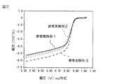
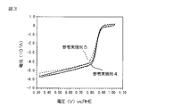
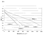
- 6 is a graph showing the activity of the oxygen side electrode in Reference Examples 1 to 3. It is a graph which shows the activity of the oxygen side electrode in Reference Examples 4 and 5. It is a graph which shows the relationship between a current density and a generated voltage.
- FIG. 1 is a schematic configuration diagram showing an embodiment of a fuel cell of the present invention.
- the fuel cell 1 is a polymer electrolyte fuel cell, and includes a plurality of fuel cells S, and is formed as a stack structure in which these fuel cells S are stacked. In FIG. 1, only one fuel cell S is shown for easy illustration.
- the fuel cell S includes a fuel side electrode 2 (anode), an oxygen side electrode 3 (cathode), and an electrolyte layer 4.
- the fuel side electrode 2 includes a catalyst (fuel side catalyst), although not particularly limited.
- the fuel side electrode 2 is formed of, for example, a catalyst carrier carrying a catalyst.
- the catalyst is not particularly limited, and examples thereof include platinum group elements (ruthenium (Ru), rhodium (Rh), palladium (Pd), osmium (Os), iridium (Ir), platinum (Pt)), iron group elements ( In accordance with periodic table (IUPAC Periodic Table of the Elements (version date 22 June 2007), etc., the same applies hereinafter) such as iron (Fe), cobalt (Co), nickel (Ni)) Examples thereof include 11th (IB) group elements of the periodic table such as copper (Cu), silver (Ag), and gold (Au).
- platinum group elements ruthenium (Ru), rhodium (Rh), palladium (Pd), osmium (Os), iridium (Ir), platinum (Pt)
- iron group elements In accordance with periodic table (IUPAC Periodic Table of the Elements (version date 22 June 2007), etc., the same applies hereinafter) such as iron (Fe), cobalt (Co), nickel (Ni)
- These catalysts can be used alone or in combination of two or more.
- the catalyst is preferably an element of Group 8 to 10 (VIII) of the periodic table, more preferably an iron group element, and still more preferably nickel.
- the catalyst loading concentration (the content ratio of the catalyst with respect to the total amount of the catalyst and the catalyst carrier) is, for example, 1 to 99% by mass, preferably 2 to 95% by mass.
- the catalyst carrier is not particularly limited, and examples thereof include a resin such as an anion exchange resin having an anion exchange group, and a porous material such as carbon.
- These catalyst carriers can be used alone or in combination of two or more.
- the catalyst carrier is preferably a resin, more preferably an anion exchange resin having an anion exchange group.
- a membrane-electrode assembly is formed together with the electrolyte layer 4 by a known method.
- an electrode ink used for forming the fuel side electrode 2 is prepared.
- 1 to 60 parts by mass of the catalyst is added to and mixed with 100 parts by mass of the catalyst carrier.
- Examples of the mixing method include known mixing methods such as dry mixing.
- the solvent examples include known solvents such as lower alcohols such as methanol, ethanol and 1-propanol, ethers such as tetrahydrofuran, and water. These solvents can be used alone or in combination of two or more. .
- the stirring temperature at this time is, for example, 10 to 30 ° C., and the stirring time is, for example, 1 to 60 minutes.
- the obtained electrode ink is applied so as to cover one surface of the electrolyte layer 4.
- Examples of the electrode ink coating method include known coating methods such as a spray method, a die coater method, and an ink jet method, and preferably a spray method.
- the applied electrode ink is dried at 10 to 40 ° C., for example.
- the amount of catalyst used is, for example, 0.01 to 10 mg / cm 2 .
- the amount of the catalyst carrier carrying the catalyst is, for example, 0.01 to 10 mg / cm 2 .
- the thickness of the fuel side electrode 2 fixed on one surface of the electrolyte layer 4 is, for example, 0.1 to 100 ⁇ m, preferably 1 to 10 ⁇ m.
- the oxygen side electrode 3 includes a first catalyst and a second catalyst.
- the first catalyst contains a first transition metal and polypyrrole.
- a first transition metal is supported on a composite composed of polypyrrole and carbon (hereinafter, this composite is referred to as “carbon composite”). Is mentioned.
- the first transition metal examples include scandium (Sc), titanium (Ti), vanadium (V), chromium (Cr), manganese (Mn), iron (Fe), cobalt (Co), nickel (Ni), and copper. (Cu), yttrium (Y), zirconium (Zr), niobium (Nb), molybdenum (Mo), technetium (Tc), ruthenium (Ru), rhodium (Rh), palladium (Pd), silver (Ag), lanthanum Transition metals such as (La), hafnium (Hf), tantalum (Ta), tungsten (W), rhenium (Re), osmium (Os), iridium (Ir), platinum (Pt), and gold (Au). .
- These first transition metals can be used alone or in combination of two or more.
- the first transition metal is preferably cobalt.
- Polypyrrole is a polymer of pyrrole (monomer), and can be obtained, for example, by polymerization of pyrrole (monomer) as described later.
- the degree of polymerization of pyrrole is not particularly limited, and is appropriately set according to the purpose and application.
- polypyrrole can also contain pyrrole (unreacted pyrrole), and the content ratio is not particularly limited, and is appropriately set according to the purpose and application.
- the blending ratio of polypyrrole is, for example, 1 to 100 parts by mass, preferably 10 to 50 parts by mass with respect to 100 parts by mass of carbon.
- Examples of carbon include known carbon such as carbon black.
- the first transition metal is supported on the carbon composite.
- a solvent 100 to 1000 parts by mass of a solvent is added to 100 parts by mass of carbon, and the solvent is stirred to prepare a carbon dispersion liquid in which carbon is dispersed in the solvent.
- an organic acid such as acetic acid or oxalic acid may be added as appropriate.
- the addition amount is, for example, 1 to 50 parts by mass with respect to 100 parts by mass of carbon.
- solvent examples include known solvents such as water, lower alcohols such as methanol, ethanol, and propanol.
- the stirring temperature is, for example, 10 to 30 ° C.
- the stirring time is, for example, 10 to 60 minutes.
- pyrrole in the carbon dispersion is polymerized.
- oxidative polymerization such as chemical oxidative polymerization and electrolytic oxidative polymerization is used.
- chemical oxidative polymerization is used.
- a catalyst for oxidative polymerization is added to a carbon dispersion containing pyrrole, and pyrrole is polymerized by stirring.
- the oxidation polymerization catalyst include known oxidation polymerization catalysts such as peroxides such as hydrogen peroxide and benzoyl peroxide, for example, permanganic acid such as potassium permanganate and magnesium permanganate, Preferably, hydrogen peroxide is used.
- the stirring temperature (polymerization temperature) for polymerizing pyrrole is, for example, 10 to 30 ° C.
- the stirring time is, for example, 10 to 90 minutes.
- the dispersion liquid in which the carbon composite of carbon and polypyrrole is dispersed is filtered and washed, and dried in a vacuum at 50 to 100 ° C., for example. Thereby, the dry powder of a carbon composite is obtained.
- the first transition metal is supported on the carbon composite.
- a solvent 100 to 3000 parts by mass of a solvent is added to 100 parts by mass of the carbon composite and stirred.
- a carbon composite dispersion liquid in which the carbon composite is dispersed in the solvent is prepared.
- the solvent mentioned above is mentioned, for example.
- 1 to 150 parts by mass of the first transition metal is dissolved in 100 to 1000 parts by mass of a solvent with respect to 100 parts by mass of the carbon composite to prepare a first transition metal-containing solution.
- this 1st transition metal containing solution is added to a carbon composite dispersion liquid, and the liquid mixture of a 1st transition metal containing solution and a carbon composite dispersion liquid is prepared by stirring.
- the stirring temperature at this time is, for example, 50 to 100 ° C., and the stirring time is, for example, 10 to 60 minutes.
- a reducing agent-containing solution containing a reducing agent is added to the mixed solution until the pH of the mixed solution of the first transition metal-containing solution and the carbon composite dispersion is in the range of 10 to 12, and then the mixed solution is added. For example, it is allowed to stand at 60-100 ° C. for 10-60 minutes. As a result, the first transition metal is supported on the carbon composite.
- Examples of the reducing agent contained in the reducing agent-containing solution include known reducing agents such as sodium borohydride, potassium borohydride, lithium borohydride, hydrazine, and preferably sodium borohydride is used. Can be mentioned.
- sodium borohydride when sodium borohydride is used as a reducing agent, it is used as an aqueous solution in which sodium borohydride is dissolved in water together with sodium hydroxide, and added to the mixture under a nitrogen atmosphere. Accordingly, contact between sodium borohydride and oxygen can be prevented, so that decomposition of sodium borohydride due to contact with oxygen can be prevented.
- the concentration of the first transition metal supported (the proportion of the first transition metal supported relative to the total amount of the first catalyst) is, for example, 0.1 to 60% by mass, preferably 1 to 40% by mass. .
- the second catalyst contains a second transition metal and a porphyrin ring-containing compound.
- examples of the second catalyst include a porphyrin complex in which a second transition metal is coordinated to a porphyrin ring-containing compound.
- Examples of the second transition metal include the same transition metals as the first transition metal.
- These second transition metals can be used alone or in combination of two or more.
- cobalt is used as the second transition metal.
- the second transition metal is preferably a transition metal of the same type as the first transition metal.
- a porphyrin ring-containing compound is defined as a compound containing a porphyrin ring (a ring in which four pyrrole rings are bonded by four methine groups (—CH ⁇ ) at the ⁇ position) in the molecular skeleton.
- Such a porphyrin ring-containing compound becomes a ligand in which, for example, a nitrogen atom contained in the porphyrin ring coordinates to the second transition metal in the porphyrin complex.
- porphyrin non-substitution thing, aka: porphine
- tetramethylporphyrin tetraethylporphyrin
- tetraphenylporphyrin tetraphenoxyporphyrin
- tetramethoxyphenylporphyrin for example, tetrakis (p -Methoxyphenyl) porphyrin and the like.
- porphyrin ring-containing compounds can be used alone or in combination of two or more.
- porphyrin ring-containing compound examples include tetramethoxyphenyl porphyrin.
- the production of the porphyrin complex is not particularly limited, and a known method can be adopted.
- a salt of a second transition metal for example, an inorganic salt such as sulfate, nitrate, chloride or phosphate, for example, an organic acid salt such as acetate or oxalate
- a porphyrin ring-containing compound for example, a porphyrin complex can be produced by mixing in a known solvent such as water, alcohol, aliphatic hydrocarbon, aromatic hydrocarbon, halogenated hydrocarbon, or nitrile.
- the blending ratio of the salt of the second transition metal and the porphyrin ring-containing compound is, for example, a ratio at which the second transition metal becomes equimolar or more with respect to the porphyrin ring-containing compound, more specifically,
- the amount of the second transition metal in the salt of the second transition metal is, for example, 1.1 to 30 mol, preferably 5 to 20 mol with respect to 1 mol of the porphyrin ring in the porphyrin ring-containing compound.
- Porphyrin complexes are also commercially available, and examples include cobalt-tetrakis (p-methoxyphenyl) porphyrin complex (CAS No. 28903-71-1, manufactured by Aldrich).
- porphyrin complexes can be used alone or in combination of two or more.
- the content ratio of the second transition metal (the content ratio of the second transition metal with respect to the total amount of the second catalyst) is, for example, 1 to 50% by mass, preferably 2 to 10% by mass.
- Such a second catalyst may be used as it is, but is preferably heat-treated before use.
- the second catalyst is heated in an inert gas (eg, nitrogen gas, argon gas, etc.) atmosphere.
- an inert gas eg, nitrogen gas, argon gas, etc.
- the heat treatment temperature is, for example, 400 to 900 ° C., preferably 600 to 800 ° C.
- the heat treatment time is 1 to 10 hours, preferably 2 to 5 hours.
- the oxygen reduction activity of the second catalyst can be improved by heat-treating the second catalyst.
- the second catalyst when the second catalyst is heat-treated, the second catalyst aggregates and grows, its effective surface area decreases, and as a result, the catalytic activity may decrease.
- pores are preferably formed on the surface of the second catalyst in order to ensure a sufficient effective surface area.
- the method for forming pores on the surface of the second catalyst is not particularly limited, and a known method, for example, a method of embedding soluble particles in the second catalyst and then removing the soluble particles on the surface of the second catalyst, etc. Is adopted.
- the second catalyst before the heat treatment and the soluble particles are mixed.
- soluble particles examples include amorphous silica, fumed silica, colloidal silica, and fired bodies thereof.
- These soluble particles can be used alone or in combination of two or more.
- the soluble particles include amorphous silica.
- the second catalyst is dissolved and / or dispersed in a solvent.
- the solvent is not particularly limited.
- a protic polar solvent for example, alcohol such as methanol, ethanol, isopropanol, glycol, etc.
- an aprotic polar solvent for example, N, N-dimethylformamide ( DMF), N, N-dimethylacetamide (DMAC), dimethyl sulfoxide (DMSO), N-methylpyrrolidone (NMP), acetonitrile, piperidine, etc.
- amines eg ammonia, eg triethylamine, pyridine etc.
- ethers for example, dioxane, tetrahydrofuran (THF), etc.
- aromatic hydrocarbons for example, benzene, toluene, xylene, etc.
- solvents can be used alone or in combination of two or more.
- ethers are preferable, and tetrahydrofuran is more preferable.
- the mixing ratio of the second catalyst and the solvent is, for example, 1000 to 100000 parts by mass, preferably 5000 to 50000 parts by mass with respect to 100 parts by mass of the second catalyst.
- the obtained solution and / or dispersion of the second catalyst and the soluble particles are mixed by a known method such as wet mixing.
- the blending ratio of the solution and / or dispersion of the second catalyst and the soluble particles is such that, for example, the soluble particles are 100 parts by mass of the second catalyst (solid content) in the solution and / or dispersion of the second catalyst.
- it is 10 to 500 parts by mass, preferably 50 to 200 parts by mass.
- the obtained second catalyst and soluble particle solution and / or dispersion liquid are dried.
- the drying temperature is, for example, ⁇ 25 to 80 ° C., preferably 15 to 50 ° C.
- the drying time is, for example, 5 to 48 hours.
- the second catalyst and soluble particles are heat-treated under the above heat treatment conditions to obtain a second catalyst having soluble particles embedded in the surface.
- the amorphous silica when used as the soluble particles, the amorphous silica may be crystallized by heat treatment to form silica (fired body).
- the second catalyst in order to remove the silica, for example, the second catalyst is subjected to alkali treatment.
- the second catalyst is impregnated with an alkaline solution such as potassium hydroxide or sodium hydroxide. Thereby, soluble particles are dissolved, and as a result, pores are formed on the surface of the second catalyst.
- an alkaline solution such as potassium hydroxide or sodium hydroxide.
- the effective surface area of the second catalyst is sufficiently secured by the pores formed on the surface even when the second catalyst aggregates and grows by heat treatment.
- the catalytic activity can be maintained.
- the method for removing the soluble particles is not limited to the above, and can be appropriately selected according to the type of the soluble particles, for example, a method of immersing in water, a method of acid treatment, and the like.
- electrode ink is prepared by the method similar to the fuel side electrode 2 mentioned above, the electrode ink is used for the electrolyte layer 4 A membrane-electrode assembly is formed together with the electrolyte layer 4 by applying and drying the surface of the other (the other to the one on which the fuel side electrode 2 is fixed).
- the oxygen-side electrode 3 fixed on the other surface of the electrolyte layer 4 different from the one surface on which the fuel-side electrode 2 is fixed can be obtained. That is, the oxygen-side electrode 3 is fixed to the other surface of the electrolyte layer 4 so that the fuel-side electrode 2 and the oxygen-side electrode 3 are disposed to face each other with the electrolyte layer 4 interposed therebetween.
- the body is formed.
- the mixing ratio of the first catalyst is more than 10 parts by mass and less than 90 parts by mass with respect to 100 parts by mass of the total amount of the first catalyst and the second catalyst.
- the oxygen reduction reaction in the oxygen side electrode can be activated, and as a result, the power generation performance of the fuel cell can be improved.
- the first catalyst and the second catalyst act antagonistically and the activity of the oxygen reduction reaction is reduced, so the first catalyst or the second catalyst.
- the power generation performance of the fuel cell is lower than when using alone.
- the first catalyst and the second catalyst act antagonistically and the activity of the oxygen reduction reaction is reduced.
- the power generation performance of the fuel cell is lower than when two catalysts are used alone.
- the mixing ratio of the first catalyst is preferably 20 to 80 parts by mass, more preferably 30 to 70 parts by mass with respect to the total amount of the first catalyst and the second catalyst of 100 parts by mass.
- the oxygen reduction reaction at the oxygen side electrode can be further activated, and as a result, the power generation performance of the fuel cell can be further improved.
- the amount of transition metal used in the first catalyst is, for example, 0.05 to 10 mg / cm 2 , preferably 0.1 to 5 mg / cm 2
- the second catalyst The amount of the transition metal used therein is, for example, 0.04 to 8 mg / cm 2 , preferably 0.08 to 4 mg / cm 2 .
- the total amount of transition metals used in the first catalyst and the second catalyst is, for example, 0.09 to 18 mg / cm 2 , preferably 0.18 to 9 mg / cm 2 .
- the thickness of the oxygen side electrode 3 fixed on the other surface of the electrolyte layer 4 is, for example, 0.1 to 100 ⁇ m, and preferably 1 to 100 ⁇ m.
- the electrolyte layer 4 is a layer that can move an anion component, and is formed using, for example, an anion exchange membrane.
- the anion exchange membrane is not particularly limited as long as it is a medium that can move hydroxide ions (OH ⁇ ), which are anion components generated at the oxygen side electrode 3, from the oxygen side electrode 3 to the fuel side electrode 2.
- a solid polymer membrane (anion exchange resin) having an anion exchange group such as a quaternary ammonium group or a pyridinium group can be used.
- the fuel battery cell S further includes a fuel supply member 5 and an oxygen supply member 6.
- the fuel supply member 5 is made of a gas impermeable conductive member, and one surface thereof is opposed to the surface of the fuel side electrode 2 opposite to the surface in contact with the electrolyte layer 4. .
- the fuel supply member 5 is formed with a fuel-side flow path 7 for bringing fuel into contact with the entire fuel-side electrode 2 as a distorted groove recessed from one surface.
- the fuel-side flow path 7 has a supply port 8 and a discharge port 9 passing through the fuel supply member 5 continuously formed at the upstream end and the downstream end, respectively.
- the oxygen supply member 6 is made of a gas impermeable conductive member, and one surface thereof is opposite to the surface in contact with the electrolyte layer 4 in the oxygen side electrode 3. Opposite contact is made with the side surface.
- the oxygen supply member 6 is also formed with an oxygen-side flow channel 10 for contacting oxygen (air) with the entire oxygen-side electrode 3 as a distorted groove recessed from one surface.
- the oxygen-side flow path 10 also has a supply port 11 and a discharge port 12 that pass through the oxygen supply member 6 continuously formed at the upstream end portion and the downstream end portion thereof.
- the fuel cell 1 is formed as a stack structure in which a plurality of fuel cells S are stacked as described above. Therefore, although not shown, the fuel supply member 5 and the oxygen supply member 6 are configured as separators in which the fuel side channel 7 and the oxygen side channel 10 are formed on both surfaces.
- the fuel cell 1 is provided with a current collector plate formed of a conductive material, and the electromotive force generated in the fuel cell 1 is provided in the current collector plate. It is taken out from the terminal.
- the fuel supply member 5 and the oxygen supply member 6 are connected by an external circuit 13, and a voltmeter 14 is interposed in the external circuit 13, thereby generating the fuel cell 1.
- the voltage can also be measured.
- power is generated by supplying air to the oxygen side channel 10 and supplying fuel to the fuel side channel 7.
- the fuel supplied to the fuel side flow path 7 is a compound containing at least hydrogen, for example, hydrogen (H 2 ), for example, methane (CH 4 ), ethane (C 2 H 6 ), propane (C 3 H 8 ).
- Hydrocarbons such as, alcohols such as methanol (CH 3 OH), ethanol (C 2 H 5 OH), hydrazine (NH 2 NH 2 ), hydrazine hydrate (NH 2 NH 2 .H 2 O), hydrazine carbonate ((NH 2 NH 2) 2 CO 2), hydrazine sulfate (NH 2 NH 2 ⁇ H 2 SO 4), monomethyl hydrazine (CH 3 NHNH 2), dimethylhydrazine ((CH 3) 2 NNH 2 , CH 3 NHNHCH 3 ), Hydrazines such as carboxylic hydrazide ((NHNH 2 ) 2 CO), for example urea (NH 2 CONH 2 ), for example ammonia ( NH 3), for example,
- a compound that does not contain carbon i.e., hydrazine (NH 2 NH 2), hydrazine hydrate (NH 2 NH 2 ⁇ H 2 O), hydrazine sulfate (NH 2 NH 2 ⁇ H 2 SO 4 ), ammonia (NH 3 ), hydroxylamine (NH 2 OH), and hydroxylamine sulfate (NH 2 OH ⁇ H 2 SO 4 ).
- the catalyst is not poisoned by CO, so that the durability can be improved and substantially zero emission can be realized.
- the fuel compound may be supplied as it is, or may be supplied as a solution such as water and / or alcohol (for example, lower alcohol such as methanol, ethanol, propanol, isopropanol).
- concentration of the fuel compound in the solution varies depending on the type of the fuel compound, but is, for example, 1 to 90% by mass, preferably 1 to 30% by mass.
- the fuel may supply the above-described fuel compound as a gas (for example, vapor).
- the power generation in the fuel cell 1 will be described more specifically, in the fuel-side electrode 2 fuel is supplied, the hydrogen from the fuel (H 2) is produced by oxidation reaction of the hydrogen (H 2), hydrogen Electrons (e ⁇ ) are released from (H 2 ), and protons (H + ) are generated. Electrons (e ⁇ ) released from hydrogen (H 2 ) reach the oxygen side electrode 3 via the external circuit 13. That is, electrons (e ⁇ ) passing through the external circuit 13 become current.
- the oxygen-side electrode 3 electrons (e ⁇ ), water (H 2 O) generated by an external supply or reaction in the fuel cell 1, and oxygen (O 2) in the air flowing through the oxygen-side channel 10.
- hydroxide ions (OH ⁇ )
- the generated hydroxide ions (OH ⁇ ) pass through the electrolyte layer 4 and reach the fuel side electrode 2.
- the hydroxide ions (OH ⁇ ) react with hydrogen (H 2 ) in the fuel at the fuel side electrode 2 to generate electrons (e - ) And water (H 2 O) are formed (see the following reaction formula (1)).
- the generated electrons (e ⁇ ) move from the fuel supply member 5 to the oxygen supply member 6 via the external circuit 13 and are supplied to the oxygen side electrode 3.
- the pressure on the fuel side electrode 2 side is 100 kPa or less, preferably 50 kPa or less, and the pressure on the oxygen side electrode 3 side is 100 kPa or less.
- it is 50 kPa or less
- the temperature of the fuel cell S is set to 30 to 100 ° C., preferably 60 to 90 ° C.
- the present invention has been described by exemplifying a solid polymer type fuel cell.
- the present invention can also be applied to various fuel cells such as a salt type and a solid electrolyte type.
- a power source for a driving motor in an automobile, a ship, an aircraft, etc. a power source in a communication terminal such as a mobile phone, etc.
- Production Example 1 (Production of first catalyst) 1) Preparation of polypyrrole carbon composite (PPy-C) To 75 mL of pure water, 10 g of carbon (Vulcan XC-72 manufactured by E-TEK, specific surface area 250 m 2 / g) and 2.5 mL of acetic acid (acetic acid concentration 100%) were added. In addition, the mixture was stirred at room temperature (about 25 ° C.) for 20 minutes to prepare a carbon dispersion in which carbon was dispersed. Subsequently, 2 g of pyrrole (manufactured by Aldrich) was added to this carbon dispersion, and the mixture was stirred at room temperature for 5 minutes.
- Py-C polypyrrole carbon composite
- Production Example 2 (Production of second catalyst) 1 g of a cobalt-tetrakis (p-methoxyphenyl) porphyrin complex (CAS No. 28903-71-1, manufactured by Aldrich) (hereinafter referred to as porphyrin complex) was dissolved in 200 mL of tetrahydrofuran (THF).
- porphyrin complex a cobalt-tetrakis (p-methoxyphenyl) porphyrin complex (CAS No. 28903-71-1, manufactured by Aldrich)
- amorphous silica (trade name: fumed silica HS-5, manufactured by Cabot Corporation) was added to the obtained solution, stirred, and dried overnight (10 hours, room temperature). Next, the obtained dried product was baked (heat treatment) at 700 ° C. for 4 hours in a nitrogen atmosphere.
- the obtained fired body was impregnated with a 7 mol / L potassium hydroxide aqueous solution to dissolve the silica contained in the fired body, and then filtered, washed, and dried.
- test piece 1 10 ⁇ L of the second ink was weighed with a micropipette and dropped onto the glassy carbon electrode. Thereafter, the glassy carbon was dried to obtain a test piece 1.
- the amount of cobalt supported on the electrode was 30 ⁇ g / cm 2 .
- test piece 1 the mass ratio of cobalt derived from cobalt-supported PPy-C to cobalt derived from a porphyrin complex (cobalt supported PPy-C-derived cobalt: porphyrin complex-derived cobalt) was 74:26. .
- test piece 2 the amount of cobalt supported on the electrode was 30 ⁇ g / cm 2 .
- test piece 2 the mass ratio of cobalt derived from cobalt-supported PPy-C to cobalt derived from a porphyrin complex (cobalt supported PPy-C-derived cobalt: porphyrin complex-derived cobalt) was 56:44. .
- the test piece 3 was obtained in the same manner as in Reference Example 1 except that.
- test piece 3 the amount of cobalt supported on the electrode was 30 ⁇ g / cm 2 .
- test piece 3 the mass ratio of cobalt derived from cobalt-supported PPy-C to cobalt derived from a porphyrin complex (cobalt derived from PPy-C supported on cobalt: cobalt derived from a porphyrin complex) was 35:65. .
- the test piece 3 was obtained in the same manner as in Reference Example 1 except that.
- test piece 3 the amount of cobalt supported on the electrode was 30 ⁇ g / cm 2 .
- test piece 3 the mass ratio of cobalt derived from cobalt-supported PPy-C and cobalt derived from the porphyrin complex (cobalt supported PPy-C-derived cobalt: porphyrin complex-derived cobalt) was 84:16. .
- test piece 3 the amount of cobalt supported on the electrode was 30 ⁇ g / cm 2 .
- test piece 3 the mass ratio of cobalt derived from cobalt-supported PPy-C to cobalt derived from a porphyrin complex (cobalt supported from PPy-C derived cobalt: cobalt derived from a porphyrin complex) was 24:76. .
- Reference Test Example 1 Measurement of oxygen side electrode activity
- the activity of the oxygen side electrode was measured by an electrochemical measurement method (cyclic voltammetry) using a rotating disk electrode.
- Test pieces 1 to 5 that is, the mixing ratio of the cobalt-supported PPy-C and the porphyrin complex (mass ratio: cobalt-supported PPy-C: porphyrin complex) was 8: 2, 7: 3, 5: 5, 3: 7, And it was confirmed that the oxygen reduction activity of the same level was obtained in all of the test pieces of 2: 8.
- Example 1 Production of membrane-electrode assembly (1-1) Formation of fuel side electrode 0.2 g of nickel and 1.1 g of 2% by mass anion exchange resin solution (solvent: THF + 1-propanol (1: 4 mass ratio)) And the resulting mixture was added to 5.1 mL of solvent (THF + 1-propanol (1: 4 mass ratio)). And it stirred at 25 degreeC for 15 minutes, and prepared the fuel side electrode ink of the anion exchange resin which carry
- solvent solvent + 1-propanol (1: 4 mass ratio
- the obtained fuel side electrode ink was applied by spraying so as to cover one surface of the anion exchange membrane.
- the fuel side electrode with a thickness of 20 ⁇ m was formed by drying at 25 ° C.
- the amount of nickel supported on the obtained fuel-side electrode was 2.5 mg / cm 2 .
- the obtained oxygen-side electrode ink was applied by a spray method so as to cover the surface of the other side of the anion exchange membrane (the other side with respect to one on which the fuel-side electrode is formed).
- the oxygen side electrode was formed by drying at room temperature.
- the amount of cobalt supported on the obtained oxygen-side electrode was 0.2 mg / cm 2 .
- a membrane-electrode assembly including a fuel side electrode, an air side electrode, and an electrolyte layer was produced.
- a carbon sheet (gas diffusion layer) of a conductive porous body is bonded to each of the fuel-side electrode layer and the air-side electrode layer of the membrane-electrode assembly obtained in the assembly of the unit cell (1).
- a unit cell was assembled by attaching an O-ring (sealing material) to the membrane-electrode assembly to which the fuel cell was bonded and sandwiching it between the fuel side separator and the air side separator.
- Example 1 (2) Further, a unit cell was assembled in the same manner as in Example 1 (2).
- Example 1 (2) Further, a unit cell was assembled in the same manner as in Example 1 (2).
- Example 1 (2) Further, a unit cell was assembled in the same manner as in Example 1 (2).
- Example 1 (2) Further, a unit cell was assembled in the same manner as in Example 1 (2).
- Test Example 1 Measurement of generated voltage
- a hydrazine hydrated 1 mol / dm 3 ⁇ 1N-KOH aqueous solution was supplied to the fuel side electrode at a rate of 2 mL / min, and the air side electrode was supplied. Supplied saturated humidified air at 50 ° C. at a rate of 0.5 L / min.
- the operating conditions of the unit cell were a supply pressure of 20 kPa ⁇ abs and a cell operating temperature of 80 ° C.
- the fuel cell of the present invention is suitably used as a power source for driving motors in automobiles, ships, airplanes, etc., and a power source in communication terminals such as mobile phones.
Landscapes
- Chemical & Material Sciences (AREA)
- General Chemical & Material Sciences (AREA)
- Chemical Kinetics & Catalysis (AREA)
- Electrochemistry (AREA)
- Engineering & Computer Science (AREA)
- Manufacturing & Machinery (AREA)
- Materials Engineering (AREA)
- Life Sciences & Earth Sciences (AREA)
- Sustainable Development (AREA)
- Sustainable Energy (AREA)
- Inert Electrodes (AREA)
- Fuel Cell (AREA)
- Catalysts (AREA)
Abstract
Description
また、このときの攪拌温度は、例えば、10~30℃、攪拌時間は、例えば、1~60分間である。
(1) 2H2+4OH-→4H2O+4e- (燃料側電極2における反応)
(2) O2+2H2O+4e-→4OH- (酸素側電極3における反応)
(3) 2H2+O2→2H2O (燃料電池1全体としての反応)
なお、この燃料電池1の運転条件は、特に限定されないが、例えば、燃料側電極2側の加圧が100kPa以下、好ましくは、50kPa以下であり、酸素側電極3側の加圧が100kPa以下、好ましくは、50kPa以下であり、燃料電池セルSの温度が30~100℃、好ましくは、60~90℃として設定される。
1)ポリピロールカーボンコンポジット(PPy-C)の作製
純水75mLに、カーボン(E-TEK社製 Vulcan XC-72、比表面積250m2/g)10gと酢酸(酢酸濃度100%)2.5mLとを加え、室温(約25℃)で20分間攪拌して、カーボンが分散したカーボン分散液を調製した。次いで、このカーボン分散液にピロール(Aldrich社製)2gを加え、室温で5分間攪拌した。さらに、このカーボン分散液に濃度10%の過酸化水素10mLを加え、室温で1時間攪拌することにより、ピロールを酸化重合させた。その後、このカーボン分散液を濾過して温水洗浄し、90℃で真空乾燥した。これにより、カーボン上にピロールが重合したPPy-C乾燥粉末を得た。
1)で得られたPPy-C乾燥粉末2gを、純水44mLに加え、80℃まで加熱しながら30分間攪拌して、PPy-Cが分散したPPy-C分散液を得た。次いで、硝酸コバルト(II)六水和物1.1gを、11mLの純水に溶解させ、コバルト含有水溶液を調製した。そして、このコバルト含有水溶液を、PPy-C分散液に加え、80℃で30分間攪拌することによって、コバルト-PPy-C混合液を得た。続いて、水素化ホウ素ナトリウム5.23gと水酸化ナトリウム0.37gとを、500mLの純水に溶解させ、アルカリ水溶液を調製した。次いで、コバルト-PPy-C混合液のpHが11.1になるまで、アルカリ水溶液を徐々に加えた後、このコバルト-PPy-C混合液80℃で30分間放置した。なお、2)におけるこの操作(アルカリ水溶液を加える操作)に至るまでの操作は全て、窒素雰囲気で行なった。その後、コバルト-PPy-C混合液を濾過して温水洗浄し、90℃で真空乾燥した。これにより、PPy-Cにコバルトが担持されたコバルト担持PPy-C(コバルトの担持濃度:10質量%)の乾燥粉末を得た。
コバルト-テトラキス(p-メトキシフェニル)ポルフィリン錯体(CAS No.28903-71-1、アルドリッチ社製)(以下、ポルフィリン錯体と称する。)1gを、テトラヒドロフラン(THF)200mLに溶解させた。
製造例1で得られたコバルト担持PPy-Cの乾燥粉末7mgと、製造例2で得られたポルフィリン錯体の焼成粉末3mgとを混合し(質量比 コバルト担持PPy-C:ポルフィリン錯体=7:3)、混合粉末10mgを得た。
製造例1で得られたコバルト担持PPy-Cの乾燥粉末5mgと、製造例2で得られたポルフィリン錯体の焼成粉末5mgとを混合した(質量比 コバルト担持PPy-C:ポルフィリン錯体=5:5)以外は、参考実施例1と同様にして、テストピース2を得た。
製造例1で得られたコバルト担持PPy-Cの乾燥粉末3mgと、製造例2で得られたポルフィリン錯体の焼成粉末7mgとを混合した(質量比 コバルト担持PPy-C:ポルフィリン錯体=3:7)以外は、参考実施例1と同様にして、テストピース3を得た。
製造例1で得られたコバルト担持PPy-Cの乾燥粉末3mgと、製造例2で得られたポルフィリン錯体の焼成粉末7mgとを混合した(質量比 コバルト担持PPy-C:ポルフィリン錯体=8:2)以外は、参考実施例1と同様にして、テストピース3を得た。
製造例1で得られたコバルト担持PPy-Cの乾燥粉末3mgと、製造例2で得られたポルフィリン錯体の焼成粉末7mgとを混合した(質量比 コバルト担持PPy-C:ポルフィリン錯体=2:8)以外は、参考実施例1と同様にして、テストピース3を得た。
酸素側電極の活性は、回転ディスク電極による電気化学測定法(サイクリックボルタンメトリー)で測定した。
(1)膜-電極接合体の作製
(1-1)燃料側電極の形成
ニッケル0.2gと、2質量%アニオン交換樹脂溶液(溶媒:THF+1-プロパノール(1:4質量比))1.1gとを混合し、得られた混合物を、溶媒(THF+1-プロパノール(1:4質量比))5.1mLに加えた。そして、25℃で15分間撹拌することにより、ニッケルを担持したアニオン交換樹脂の燃料側電極インクを調製した。
製造例1で得られたコバルト担持PPy-Cの乾燥粉末0.1gと、製造例2で得られたポルフィリン錯体の焼成粉末0.1gと(質量比 コバルト担持PPy-C:ポルフィリン錯体=5:5)、2質量%アニオン交換樹脂溶液1.9g(溶媒:THF+1-プロパノール(1:4質量比))とを混合した。
(2)単位セルの組立
(1)で得られた膜-電極接合体の燃料側電極層および空気側電極層それぞれに導電性多孔質体のカーボンシート(ガス拡散層)を接合し、カーボンシートが接合された膜-電極接合体にOリング(シール材)を取り付け、燃料側セパレータと空気側セパレータとで挟み込むことにより、単位セルを組み立てた。
上記(1-2)酸素側電極の形成において、製造例1で得られたコバルト担持PPy-Cの乾燥粉末0.2gを用い、製造例2で得られたポルフィリン錯体の焼成粉末を混合しなかった(質量比 コバルト担持PPy-C:ポルフィリン錯体=10:0)以外は、実施例1(1)と同様にして、膜-電極接合体を作製した。酸素側電極のコバルト担持量は、0.2mg/cm2であった。
上記(1-2)酸素側電極の形成において、製造例1で得られたコバルト担持PPy-Cの乾燥粉末0.18gと、製造例2で得られたポルフィリン錯体の焼成粉末0.02gとを混合した(質量比 コバルト担持PPy-C:ポルフィリン錯体=9:1)以外は、実施例1(1)と同様にして、膜-電極接合体を作製した。酸素側電極のコバルト担持量は、0.2mg/cm2であった。
上記(1-2)酸素側電極の形成において、製造例1で得られたコバルト担持PPy-Cの乾燥粉末0.02gと、製造例2で得られたポルフィリン錯体の焼成粉末0.18gとを混合した(質量比 コバルト担持PPy-C:ポルフィリン錯体=1:9)以外は、実施例1(1)と同様にして、膜-電極接合体を作製した。酸素側電極のコバルト担持量は、0.2mg/cm2であった。
上記(1-2)酸素側電極の形成において、製造例2で得られたポルフィリン錯体の焼成粉末0.2gを用い、製造例1で得られたコバルト担持PPy-Cの乾燥粉末を混合しなかった(質量比 コバルト担持PPy-C:ポルフィリン錯体=0:10)以外は、実施例1(1)と同様にして、膜-電極接合体を作製した。酸素側電極のコバルト担持量は、0.2mg/cm2であった。
実施例1および比較例1~4で組み立てた単位セルに対して、燃料側電極には水加ヒドラジン1mol/dm3・1N-KOH水溶液を、2mL/minの速度で供給し、空気側電極には、50℃の飽和加湿空気を0.5L/minの速度で供給した。なお、単位セルの運転条件は、供給圧を20kPa・absとし、セル運転温度は80℃とした。
Claims (3)
- アニオン成分を移動させることができる電解質と、前記電解質を挟んで対向配置された燃料側電極および酸素側電極とを含み、
前記酸素側電極は、第1遷移金属およびポリピロールを含む第1触媒と、第2遷移金属およびポルフィリン環含有化合物を含む第2触媒とを含み、
前記第1触媒の配合割合が、前記第1触媒および前記第2触媒の総量100質量部に対して、10質量部を超過し、90質量部未満であることを特徴とする、燃料電池。 - 前記第1触媒の配合割合が、前記第1触媒および前記第2触媒の総量100質量部に対して、20~80質量部であることを特徴とする、請求項1に記載の燃料電池。
- 前記第1遷移金属および前記第2遷移金属が、コバルトであることを特徴とする、請求項1に記載の燃料電池。
Priority Applications (4)
| Application Number | Priority Date | Filing Date | Title |
|---|---|---|---|
| US13/636,606 US8945791B2 (en) | 2010-03-31 | 2011-03-23 | Oxygen side electrode for a fuel cell |
| CN201180016513.6A CN102844921B (zh) | 2010-03-31 | 2011-03-23 | 燃料电池 |
| DE112011101133T DE112011101133T8 (de) | 2010-03-31 | 2011-03-23 | Brennstoffzelle |
| JP2012508225A JP5813627B2 (ja) | 2010-03-31 | 2011-03-23 | 燃料電池 |
Applications Claiming Priority (2)
| Application Number | Priority Date | Filing Date | Title |
|---|---|---|---|
| JP2010083718 | 2010-03-31 | ||
| JP2010-083718 | 2010-03-31 |
Publications (1)
| Publication Number | Publication Date |
|---|---|
| WO2011122399A1 true WO2011122399A1 (ja) | 2011-10-06 |
Family
ID=44712109
Family Applications (1)
| Application Number | Title | Priority Date | Filing Date |
|---|---|---|---|
| PCT/JP2011/056874 Ceased WO2011122399A1 (ja) | 2010-03-31 | 2011-03-23 | 燃料電池 |
Country Status (5)
| Country | Link |
|---|---|
| US (1) | US8945791B2 (ja) |
| JP (1) | JP5813627B2 (ja) |
| CN (1) | CN102844921B (ja) |
| DE (1) | DE112011101133T8 (ja) |
| WO (1) | WO2011122399A1 (ja) |
Cited By (5)
| Publication number | Priority date | Publication date | Assignee | Title |
|---|---|---|---|---|
| JP2014060053A (ja) * | 2012-09-18 | 2014-04-03 | Daihatsu Motor Co Ltd | 燃料電池の製造方法 |
| US8906562B2 (en) * | 2011-12-20 | 2014-12-09 | Samsung Electronics Co., Ltd. | Polymeric compound, oxygen permeable membrane, oxygen permeable composite, electrochemical device |
| JP2015229123A (ja) * | 2014-06-03 | 2015-12-21 | 国立大学法人九州工業大学 | 金属担持材料、金属担持材料の製造方法及び触媒の製造方法 |
| JP2016005826A (ja) * | 2014-06-20 | 2016-01-14 | ダイハツ工業株式会社 | 酸素還元触媒および燃料電池 |
| WO2016035321A1 (ja) * | 2014-09-01 | 2016-03-10 | 国立大学法人 東京大学 | 共有結合性有機構造体を含む導電性ハイブリッド材料 |
Families Citing this family (3)
| Publication number | Priority date | Publication date | Assignee | Title |
|---|---|---|---|---|
| JPH0831447B2 (ja) | 1989-10-30 | 1996-03-27 | 株式会社半導体エネルギー研究所 | 気相エッチング方法 |
| JP6128099B2 (ja) | 2014-11-07 | 2017-05-17 | トヨタ自動車株式会社 | 膜電極接合体の製造方法および膜電極接合体 |
| TWI609719B (zh) | 2016-12-09 | 2018-01-01 | National Taiwan University Of Science And Technology | 用於燃料電池的觸媒及其製造方法 |
Citations (6)
| Publication number | Priority date | Publication date | Assignee | Title |
|---|---|---|---|---|
| JP2000157871A (ja) * | 1998-11-27 | 2000-06-13 | Japan Science & Technology Corp | 酸素4電子還元触媒 |
| JP2005044664A (ja) * | 2003-07-23 | 2005-02-17 | Toyota Central Res & Dev Lab Inc | 電極触媒及びその製造方法 |
| JP2005066592A (ja) * | 2003-08-05 | 2005-03-17 | Toyota Motor Corp | 触媒材料およびその製造方法 |
| WO2006083029A1 (ja) * | 2005-02-03 | 2006-08-10 | Toyota Jidosha Kabushiki Kaisha | 触媒材料およびその製造方法 |
| JP2007237092A (ja) * | 2006-03-09 | 2007-09-20 | Toyota Motor Corp | 触媒材料の製造方法 |
| WO2008117485A1 (ja) * | 2007-03-27 | 2008-10-02 | Daihatsu Motor Co., Ltd. | 燃料電池 |
Family Cites Families (1)
| Publication number | Priority date | Publication date | Assignee | Title |
|---|---|---|---|---|
| CN1284258C (zh) | 2005-02-21 | 2006-11-08 | 武汉理工大学 | 导电高聚物修饰一维纳米碳为载体的电催化剂及制备方法 |
-
2011
- 2011-03-23 WO PCT/JP2011/056874 patent/WO2011122399A1/ja not_active Ceased
- 2011-03-23 JP JP2012508225A patent/JP5813627B2/ja not_active Expired - Fee Related
- 2011-03-23 DE DE112011101133T patent/DE112011101133T8/de not_active Expired - Fee Related
- 2011-03-23 CN CN201180016513.6A patent/CN102844921B/zh not_active Expired - Fee Related
- 2011-03-23 US US13/636,606 patent/US8945791B2/en active Active
Patent Citations (6)
| Publication number | Priority date | Publication date | Assignee | Title |
|---|---|---|---|---|
| JP2000157871A (ja) * | 1998-11-27 | 2000-06-13 | Japan Science & Technology Corp | 酸素4電子還元触媒 |
| JP2005044664A (ja) * | 2003-07-23 | 2005-02-17 | Toyota Central Res & Dev Lab Inc | 電極触媒及びその製造方法 |
| JP2005066592A (ja) * | 2003-08-05 | 2005-03-17 | Toyota Motor Corp | 触媒材料およびその製造方法 |
| WO2006083029A1 (ja) * | 2005-02-03 | 2006-08-10 | Toyota Jidosha Kabushiki Kaisha | 触媒材料およびその製造方法 |
| JP2007237092A (ja) * | 2006-03-09 | 2007-09-20 | Toyota Motor Corp | 触媒材料の製造方法 |
| WO2008117485A1 (ja) * | 2007-03-27 | 2008-10-02 | Daihatsu Motor Co., Ltd. | 燃料電池 |
Cited By (5)
| Publication number | Priority date | Publication date | Assignee | Title |
|---|---|---|---|---|
| US8906562B2 (en) * | 2011-12-20 | 2014-12-09 | Samsung Electronics Co., Ltd. | Polymeric compound, oxygen permeable membrane, oxygen permeable composite, electrochemical device |
| JP2014060053A (ja) * | 2012-09-18 | 2014-04-03 | Daihatsu Motor Co Ltd | 燃料電池の製造方法 |
| JP2015229123A (ja) * | 2014-06-03 | 2015-12-21 | 国立大学法人九州工業大学 | 金属担持材料、金属担持材料の製造方法及び触媒の製造方法 |
| JP2016005826A (ja) * | 2014-06-20 | 2016-01-14 | ダイハツ工業株式会社 | 酸素還元触媒および燃料電池 |
| WO2016035321A1 (ja) * | 2014-09-01 | 2016-03-10 | 国立大学法人 東京大学 | 共有結合性有機構造体を含む導電性ハイブリッド材料 |
Also Published As
| Publication number | Publication date |
|---|---|
| CN102844921A (zh) | 2012-12-26 |
| CN102844921B (zh) | 2015-06-24 |
| US20130011765A1 (en) | 2013-01-10 |
| JPWO2011122399A1 (ja) | 2013-07-08 |
| DE112011101133T5 (de) | 2013-02-07 |
| JP5813627B2 (ja) | 2015-11-17 |
| US8945791B2 (en) | 2015-02-03 |
| DE112011101133T8 (de) | 2013-04-25 |
Similar Documents
| Publication | Publication Date | Title |
|---|---|---|
| JP5813627B2 (ja) | 燃料電池 | |
| JP4993867B2 (ja) | 燃料電池 | |
| JP5235863B2 (ja) | 燃料電池 | |
| CN113424341B (zh) | 用于燃料电池的催化剂 | |
| JP5800467B2 (ja) | 酸素還元触媒および燃料電池 | |
| JP2013116458A (ja) | 触媒担体の製造方法、複合触媒の製造方法、複合触媒、およびこれを用いた直接酸化型燃料電池 | |
| US20100068591A1 (en) | Fuel cell catalyst, fuel cell cathode and polymer electrolyte fuel cell including the same | |
| JP5715429B2 (ja) | 酸素還元触媒および燃料電池 | |
| JP6581342B2 (ja) | 燃料電池 | |
| JP2012110839A (ja) | 触媒組成物 | |
| KR20070035710A (ko) | 연료 전지용 촉매, 그의 제조 방법 및 그를 포함하는 연료전지 시스템 | |
| JP2015044153A (ja) | 酸素還元触媒の製造方法 | |
| WO2014156966A2 (ja) | 酸素還元触媒および燃料電池 | |
| JP6437233B2 (ja) | 膜電極接合体 | |
| JP2016035890A (ja) | 酸素還元触媒 | |
| JP5456534B2 (ja) | カソード触媒およびその製造方法、および、燃料電池 | |
| JP6581343B2 (ja) | 燃料電池および燃料電池の製造方法 | |
| JP2016081838A (ja) | 膜電極接合体 | |
| JP6719351B2 (ja) | 燃料電池 | |
| JP6462294B2 (ja) | 酸素還元触媒、その製造方法および燃料電池 | |
| JP6359418B2 (ja) | 燃料電池 | |
| JP2018078016A (ja) | 燃料電池 | |
| JP2016146312A (ja) | 酸素還元触媒 | |
| JP2017091684A (ja) | 燃料電池 | |
| JP2016033872A (ja) | アノード触媒 |
Legal Events
| Date | Code | Title | Description |
|---|---|---|---|
| WWE | Wipo information: entry into national phase |
Ref document number: 201180016513.6 Country of ref document: CN |
|
| 121 | Ep: the epo has been informed by wipo that ep was designated in this application |
Ref document number: 11762631 Country of ref document: EP Kind code of ref document: A1 |
|
| WWE | Wipo information: entry into national phase |
Ref document number: 2012508225 Country of ref document: JP |
|
| WWE | Wipo information: entry into national phase |
Ref document number: 13636606 Country of ref document: US |
|
| WWE | Wipo information: entry into national phase |
Ref document number: 1120111011334 Country of ref document: DE Ref document number: 112011101133 Country of ref document: DE |
|
| 122 | Ep: pct application non-entry in european phase |
Ref document number: 11762631 Country of ref document: EP Kind code of ref document: A1 |