WO2011121943A1 - ターボファン及びこれを装備した空気調和機の室内機 - Google Patents
ターボファン及びこれを装備した空気調和機の室内機 Download PDFInfo
- Publication number
- WO2011121943A1 WO2011121943A1 PCT/JP2011/001718 JP2011001718W WO2011121943A1 WO 2011121943 A1 WO2011121943 A1 WO 2011121943A1 JP 2011001718 W JP2011001718 W JP 2011001718W WO 2011121943 A1 WO2011121943 A1 WO 2011121943A1
- Authority
- WO
- WIPO (PCT)
- Prior art keywords
- blade
- trailing edge
- groove
- shroud
- turbofan
- Prior art date
Links
Images

Classifications
-
- F—MECHANICAL ENGINEERING; LIGHTING; HEATING; WEAPONS; BLASTING
- F04—POSITIVE - DISPLACEMENT MACHINES FOR LIQUIDS; PUMPS FOR LIQUIDS OR ELASTIC FLUIDS
- F04D—NON-POSITIVE-DISPLACEMENT PUMPS
- F04D29/00—Details, component parts, or accessories
- F04D29/26—Rotors specially for elastic fluids
- F04D29/28—Rotors specially for elastic fluids for centrifugal or helico-centrifugal pumps for radial-flow or helico-centrifugal pumps
- F04D29/281—Rotors specially for elastic fluids for centrifugal or helico-centrifugal pumps for radial-flow or helico-centrifugal pumps for fans or blowers
-
- F—MECHANICAL ENGINEERING; LIGHTING; HEATING; WEAPONS; BLASTING
- F04—POSITIVE - DISPLACEMENT MACHINES FOR LIQUIDS; PUMPS FOR LIQUIDS OR ELASTIC FLUIDS
- F04D—NON-POSITIVE-DISPLACEMENT PUMPS
- F04D29/00—Details, component parts, or accessories
- F04D29/26—Rotors specially for elastic fluids
- F04D29/28—Rotors specially for elastic fluids for centrifugal or helico-centrifugal pumps for radial-flow or helico-centrifugal pumps
- F04D29/30—Vanes
-
- F—MECHANICAL ENGINEERING; LIGHTING; HEATING; WEAPONS; BLASTING
- F05—INDEXING SCHEMES RELATING TO ENGINES OR PUMPS IN VARIOUS SUBCLASSES OF CLASSES F01-F04
- F05D—INDEXING SCHEME FOR ASPECTS RELATING TO NON-POSITIVE-DISPLACEMENT MACHINES OR ENGINES, GAS-TURBINES OR JET-PROPULSION PLANTS
- F05D2240/00—Components
- F05D2240/20—Rotors
- F05D2240/30—Characteristics of rotor blades, i.e. of any element transforming dynamic fluid energy to or from rotational energy and being attached to a rotor
- F05D2240/304—Characteristics of rotor blades, i.e. of any element transforming dynamic fluid energy to or from rotational energy and being attached to a rotor related to the trailing edge of a rotor blade
-
- F—MECHANICAL ENGINEERING; LIGHTING; HEATING; WEAPONS; BLASTING
- F05—INDEXING SCHEMES RELATING TO ENGINES OR PUMPS IN VARIOUS SUBCLASSES OF CLASSES F01-F04
- F05D—INDEXING SCHEME FOR ASPECTS RELATING TO NON-POSITIVE-DISPLACEMENT MACHINES OR ENGINES, GAS-TURBINES OR JET-PROPULSION PLANTS
- F05D2250/00—Geometry
- F05D2250/20—Three-dimensional
- F05D2250/29—Three-dimensional machined; miscellaneous
- F05D2250/294—Three-dimensional machined; miscellaneous grooved
Definitions
- the present invention relates to a turbo fan and an indoor unit of an air conditioner equipped with the same, and more particularly to a turbo fan that sends out air that has been dehumidified / humidified or air-conditioned, and an indoor unit of an air conditioner equipped with the turbo fan.
- a turbo fan in which fan blades are formed in a three-dimensional shape has been widely used. That is, the turbofan blows out air sucked in the inner peripheral portion toward the outer periphery, and includes a disc-shaped main plate, an annular shroud disposed to face the main plate, and the main plate and the shroud. It is formed from a plurality of blades (wings) connected at both ends. And several inventions which respond to the request
- a blade having a “saw tooth shape” extending in the blade width direction while alternately bending the blade trailing edge in the blade length direction is disclosed (for example, see Patent Document 1).
- a plurality of “ribs” arranged in parallel with a predetermined interval in a direction perpendicular to the rotation axis are provided on the rotational direction surface (positive pressure surface) of the blade trailing edge (for example, , See Patent Document 2).
- “riblets” arranged on the impeller rotating shaft are provided on the entire or part of the pressure surface side of the blades (see, for example, Patent Document 3).
- Japanese Patent No. 3092554 (pages 4-5, Fig. 1) JP-A-9-126190 (page 3, FIG. 1) Japanese Patent No. 2669448 (pages 3-4, Fig. 1)
- the turbofan disclosed in Patent Document 2 has a plurality of “ribs” arranged in parallel to the surface (positive pressure surface) on the rotation direction side of the blade trailing edge in parallel to the rotation axis at predetermined intervals. Is provided. For this reason, there has been a problem that the flow of the blade pressure surface collides with the ribs or gets over the ribs and is largely separated, the discharge vortex becomes large, and noise is generated (deteriorates).
- a fine groove-shaped “riblet” perpendicular to the rotation axis is formed on all or part of the surface (positive pressure surface) on the rotational direction side of the blade. For this reason, air flows along the riblet on the surface of the blade pressure surface, but at the position of the blade trailing edge, which is the tip on the outer periphery of the blade, the blade pressure surface and the blade suction surface coincide ( Since the trailing edge of the blade is formed), the shear turbulence is generated by the difference in velocity between the flow from the blade pressure surface and the flow from the blade suction surface. For this reason, there is a problem that a large discharge vortex is generated and noise is generated (deteriorates).
- the present invention has been made to solve the above-described problems, and has a turbofan capable of ensuring the blade area and suppressing noise generation, and an air conditioner equipped with the turbofan.
- the purpose is to obtain the indoor unit.
- a turbofan according to the present invention includes a disc-shaped main plate having protruding bosses formed in a predetermined range including a rotation center, an annular shroud disposed to face the main plate, and both ends of the main plate. And a plurality of blades joined to the shroud, The blade trailing edge of the blade is located on a virtual cylinder formed by the outer periphery of the disk and the outer periphery of the shroud, and the blade leading edge of the blade is closer to the rotation center than the blade trailing edge.
- a plurality of trailing edge horizontal grooves of a predetermined length reaching the trailing edge of the blade are formed on the outer peripheral surface of the blade, which is a surface far from the rotation center,
- the trailing edge horizontal groove is characterized in that it communicates at the end of the blade trailing edge with an inner peripheral surface of the blade that is perpendicular to the rotation center and is closer to the rotation center.
- a plurality of trailing edge horizontal grooves having a predetermined length perpendicular to the rotation center are formed at the blade trailing edge portion of the blade outer peripheral surface which is the blade pressure surface, and the trailing edge horizontal groove is a blade suction surface. Since it communicates with a certain blade inner peripheral surface, the following effects are obtained. (A) Part of the air flow from the trailing edge of the blade pressure surface to the trailing edge of the blade flows into the plurality of trailing edge horizontal grooves, and the rest flows on the blade trailing edge surface (the trailing edge horizontal grooves To the end of the trailing edge of the blade.
- the blade area is only slightly reduced, and the influence of deteriorating the blowing efficiency is suppressed.
- the flow of air into the trailing edge horizontal groove suppresses the development of the boundary layer on the blade pressure surface.
- a part of the air flow on the blade pressure surface side on the blade suction surface side where the boundary layer gradually develops from the inner periphery side to the outer periphery side (from windward to leeward) of the impeller since it is supplied via the groove communicating portion, separation of the air flow at the blade suction surface is prevented, and shear disturbance due to the wind speed difference between the blade suction surface and the blade pressure surface is suppressed.
- the ventilation resistance In a position far away from the heat exchanger, the ventilation resistance is relatively small, and in the position where the blade trailing edge is close to the center of the side of the heat exchanger (the position where the blade trailing edge is relatively close to the heat exchanger), the ventilation resistance is Since it becomes relatively large, a pulsation phenomenon of ventilation resistance occurs.
- the draft resistance gradually increases (the trailing edge of the blade approaches the center of the side)
- a part of the air flow flows into the trailing edge horizontal groove and the air flow is rectified. Is less likely to occur.
- the airflow resistance gradually decreases (the trailing edge of the blade approaches the corner), an air flow is formed along the blade surface, and separation of the air flow is difficult to occur.
- the longitudinal cross-sectional view which shows the indoor unit of the air conditioner which concerns on Embodiment 1 of this invention.
- the horizontal sectional view which shows the indoor unit of the air conditioner which concerns on Embodiment 1 of this invention.
- the perspective view which shows the turbo fan which concerns on Embodiment 2 of this invention.
- the longitudinal cross-sectional view and side view which show typically the turbofan shown in FIG.
- the side view which expands and shows the blade
- the horizontal sectional view which expands and shows the blade
- the characteristic view which shows the relationship between the shape of the trailing edge horizontal groove
- the characteristic view which shows the relationship between the shape of the trailing edge horizontal groove
- the side view which shows typically the modification of the trailing edge horizontal groove
- the longitudinal cross-sectional view which shows typically the modification of the trailing edge horizontal groove
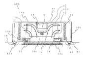
- FIG. 1 and 2 illustrate an indoor unit of an air conditioner according to Embodiment 1 of the present invention.
- FIG. 1 is a schematic longitudinal sectional view
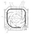
- FIG. 2 is a schematic horizontal sectional view. It is.
- a ceiling-embedded air conditioner will be described as an example.
- the present invention is not limited to this, and ventilation of a filter, a heat exchanger, or the like is possible on the fan suction side and the blowout side.
- the present invention can be widely applied to an indoor unit of an air conditioner equipped with a turbo fan having an appropriate pressure loss body.
- an indoor unit 100 of an air conditioner (hereinafter may be simply referred to as “indoor unit”) 100 is housed in a recess formed in a ceiling 18 of a room 17.
- the main body 10 is a casing formed by a rectangular top plate 10a and a side plate 10b erected around the top plate 10a.
- a surface facing the top plate 10a is opened, and a makeup is formed on the opened surface.
- a panel 11 is installed. That is, the indoor unit 100 is installed on the ceiling 18 in such a posture that the top plate 10a is upward and the decorative panel 11 is downward. At this time, the lower surface of the decorative panel 11 faces (exposes) the room 17 while slightly protruding from the lower surface of the ceiling 18 (the surface on the room 17 side).
- a suction grill 11a that is an air inlet to the main body 10
- a filter 12 that removes dust contained in the air after passing through the suction grill 11a
- each side of the decorative panel 11 It has the panel fan blower outlet 11b formed along.
- Each panel fan outlet 11b is provided with a wind direction vane 13 for changing the direction of the blown air.
- a fan motor 15 is installed on the top plate 10 a, and the turbo fan 1 is fixed to the rotating shaft of the fan motor 15.
- a bell mouth 14 that forms a suction air path from the suction grill 11 a to the turbo fan 1 is installed so as to be sandwiched between the filter 12 and the turbo fan 1.
- a heat exchanger 16 that surrounds the outer periphery of the turbofan 1 and is formed in a substantially square shape in plan view is installed, and the heat exchanger 16 is connected to the outdoor unit by a connection pipe (not shown).
- the air in the room 17 is sucked through the suction grille 11a of the decorative panel 11 and is removed when passing through the filter 12 to be sucked into the main body. It flows into the bell mouth 14 installed in the path 10c. Then, after passing through the bell mouth 14, it is sucked into the turbo fan 1 substantially upward (substantially parallel to the rotation axis of the fan motor 15). Thereafter, air is blown from the turbo fan 1 toward the heat exchanger 16 in a substantially horizontal direction (a direction substantially perpendicular to the rotation axis of the fan motor 15).
- the air that has been subjected to heat exchange or dehumidification in the heat exchanger 16 passes through the main body blowing air passage 10d and the panel fan air outlet 11b, and is controlled in air direction by the air direction vane 13. However, it is blown out into the room 17.
- the turbo fan 1 will be described in detail in the second embodiment.
- FIGS. 3 to 11 illustrate a turbo fan according to Embodiment 2 of the present invention.
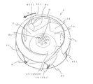
- FIG. 3 is a perspective view schematically showing
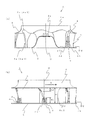
- FIG. 4 is a longitudinal sectional view and a side view schematically showing
- FIG. 5 is an enlarged side view showing a part (blade leading edge)
- FIG. 6 is a horizontal sectional view showing an enlarged part (blade)
- FIG. 7 is an enlarged part (blade trailing edge).
- FIG. 8 and FIG. 9 are characteristic diagrams showing the relationship between the shape of part (rear edge horizontal groove) and the noise effect
- FIG. 10 schematically shows a modification of part (rear edge horizontal groove).
- FIG. 11 is a side view
- FIG. 11 is a side view
- FIG. 11 is a longitudinal sectional view schematically showing a modification of a part (rear edge horizontal groove).
- the same reference numerals are given to the same or corresponding parts, and a part of the description is omitted.
- 3 to 7 and 10 for the sake of convenience of explanation, the turbofan sucks air from the upper side to the lower side of the paper surface and blows it out in the substantially horizontal direction of the paper surface.
- the posture of the turbo fan 1 in the indoor unit 100 depicted in the first mode is upside down.
- the turbofan 1 includes a substantially disk-shaped main plate 2 whose center protrudes in a mountain shape, a substantially annular shroud 3 disposed opposite to the main plate 2, a main plate 2, and a shroud 3. And a plurality of blades 4 joined to each other.
- the shroud 3 has a substantially morning glory shape (a circular ring with a substantially arc-shaped cross section), and the central opening portion forms the fan suction port 1a and the suction air guide wall.
- a boss 2a which is a fixed portion to which the rotation shaft of the fan motor 15 is fixed, is integrally formed on the top of the protrusion at the center of the main plate 2.
- rotation center O (O) the center of the rotation axis
- the blade 4 has a thickness T (the distance between the blade outer peripheral surface (blade positive pressure surface) and the blade inner peripheral surface (blade negative pressure surface) in the horizontal cross section orthogonal to the rotation axis) in the height direction.
- the hollow structure has a taper that becomes thinner and closer to the shroud 3 and has a cavity inside. The cavity communicates with the opening formed in the main plate 2 and opens on the lower surface of the main plate 2 (outward of the impeller).
- a range surrounded by a pair of adjacent blades 4, shroud 3, and main plate 2 serves as a flow path for the air flow, and an end on the outer peripheral side thereof is a blower outlet 1 b.
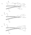
- the blade leading edge portion 4a of the blade 4 is substantially upright on the main plate 2 in a range close to the main plate 2 of the blade outer peripheral surface (same as the blade positive pressure surface) 4c, and on the shroud 3 of the blade outer peripheral surface 4c.
- the blade inner peripheral surface (same as the blade negative pressure surface) 4d side of the blade leading edge 4a is defined as a “blade leading edge 4a1”
- a line connecting the thickness center in the height direction of the blade leading edge 4a1 is defined as “ The vertical sled line Q1 ".
- the angle formed by the vertical warp line Q1 and the rotation center O is defined as “blade leading edge 4a1. Bend angle ⁇ 1 ”.
- wing 4 and the shroud 3 is made into the "blade shroud side coupling
- a line connecting the thickness centers is defined as “vertical sled line Q2 (not shown)”.
- an angle formed by the vertical sled line Q2 and the rotation center O (same as a parallel line O ′ parallel to the rotation center O assumed in the plane) is defined as “blade shroud side coupling portion 4g.
- the “curve angle ⁇ 2 at the blade shroud side coupling portion 4g” is smaller than the “curve angle ⁇ 1 at the blade leading edge 4a1”, and the curve angle ⁇ gradually becomes closer to the center of the impeller (rotation center O).
- the blade shroud side front edge portion 4a2 is formed to curve outward (in a direction away from the rotation center O) of the turbofan 1 as it approaches the center.
- the blade leading edge 4a1 (the end where the blade outer peripheral surface (blade positive pressure surface) 4c and the blade inner peripheral surface (blade negative pressure surface) 4d are connected) is separated from the main plate 2 and the shroud 3
- the shape is curved toward the outside of the impeller (in the direction away from the rotation center O) as it approaches. For this reason, attraction
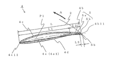
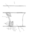
- a straight line connecting the main plate side end point 4a11 of the blade inner peripheral side front edge portion and the main plate side end point 4b11 of the blade rear edge portion is referred to as a “main plate side blade chord line 4e1” (see FIG. 6).
- a plurality of trailing edge horizontal grooves 5 having a predetermined length L2 reaching the blade trailing edge portion 4b are formed in the blade outer peripheral surface 4c of the blade 4 in the horizontal direction (in a plane perpendicular to the rotation center O).
- the trailing edge horizontal groove 5 is formed with a groove communication portion 5b at the end of the blade trailing edge portion 4b and communicates with the blade inner peripheral surface 4d. Therefore, the trailing edge horizontal groove 5 is a combination of a groove portion (a recessed portion, hereinafter referred to as a “groove recessed portion”) 5a having a predetermined depth on the blade outer peripheral surface 4c and the groove communicating portion 5b. Then, since the bottom of the groove recess 5a approaches the blade inner peripheral surface 4d, the thickness of the blade 4 is thin in the groove recess 5a (see FIG. 6).
- the length of the main plate side chord line 4e1 is set to the main plate side chord line L
- the length of the trailing edge horizontal groove 5 is set to L2
- the length of the groove communication portion 5b is L3. 6 shows the trailing edge horizontal groove 5 closest to the main plate 2 in the height direction. Similarly, the trailing edge horizontal grooves 5 are parallel to each other at positions away from the main plate 2 in the height direction. It is formed (see FIGS. 4 and 7).
- fan blowing height H the blade trailing edge height (hereinafter referred to as "fan blowing height") H, the distance upward from the main plate 2 of the blade trailing edge 4b.
- a trailing edge horizontal groove 5 is formed in a range of H1 and a range of a distance H2 downward from the shroud 3 of the blade trailing edge 4b.
- the distance H2 which is the installation range of the rear edge horizontal groove 5 on the shroud 3 side, is set to be equal to or less than half the fan blowing height H (0 to 50%), thereby obtaining the following effects.
- the height of the trailing edge horizontal groove 5 (same as the width in the height direction of the groove recess 5a) is defined as the groove width D1, and the gap between the grooves 5a and 5a
- the width in the height direction of the surface portion 6 is defined as a groove interval D2.
- the edge closer to the rotation center O where the blade outer peripheral surface 4c and the blade inner peripheral surface 4d are connected is referred to as the “blade leading edge 4a1”, and the one far from the rotation center O.
- the edge “blade trailing edge 4b1” a straight line connecting the edges is referred to as “blade chord line 4e”.
- the trailing edge horizontal groove 5 formed at the position in the height direction also reads “L” as the length of the chord line 4e (actually, the length of the chord line 4e depends on the position in the height direction. The length is not necessarily constant).
- the plurality of trailing edge horizontal grooves 5 formed on the blade trailing edge portion 4b of the turbofan 1 include the groove recess 5a extending in the horizontal direction formed on the blade outer peripheral surface (blade positive pressure surface) 4c, and the blade At the end point of the trailing edge 4b, there is a groove communication portion 5b that communicates the blade outer peripheral surface (blade positive pressure surface) 4c and the blade inner peripheral surface (blade negative pressure surface) 4d. Accordingly, the blade area does not decrease as in the conventional sawtooth shape (see Patent Document 1), and the speed is increased and rectified by the flow of air into the groove recess 5a.
- the blade positive pressure side and the blade negative pressure side communicate with each other in the groove communication portion 5b, the flow diffuses with respect to the increase or decrease in the ventilation resistance, so that the separation of the air flow hardly occurs and the noise can be reduced. It has become.
- the flow on the blade surface is attracted to the groove concave portion 5a formed on the blade trailing edge 4b side of the blade outer peripheral surface 4c, and the separation of the air flow is suppressed.
- the air flow is partially attracted to the shroud 3 side, and the wind speed distribution tends to be uniform in the height direction of the fan outlet 1b, but the rear edge horizontal groove 5 makes it easy to flow in the radial direction, The drift of the flow to the shroud 3 side is suppressed. Therefore, the air flow can be made more uniform, less affected by changes in ventilation resistance, and further noise reduction can be achieved. As a result, it is possible to obtain the turbo fan 1 and the indoor unit 100 that have lower noise and less noise change due to disturbance.
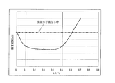
- the horizontal axis is the ratio (L2 / L) of the length L2 of the trailing edge horizontal groove 5 to the main plate side chord line L, and the vertical axis is the noise generated by the turbofan in which the trailing edge horizontal groove 5 is not formed. Is the ratio of noise generated by the turbofan 1 in which the trailing edge horizontal groove 5 is formed (hereinafter referred to as “noise effect”).
- the length L2 of the trailing edge horizontal groove 5 is long (L2 ⁇ 0.5 ⁇ L)
- the static pressure rise on the blade outer peripheral surface 4c is small and the blowing efficiency is deteriorated, and the fan rotation speed is increased to blow the necessary air volume. Is required.
- the length L2 of the trailing edge horizontal groove 5 is preferably formed so as to be 10% to 50% of the chord length L (0.1 ⁇ L ⁇ L2 ⁇ 0.5 ⁇ L). By doing so, it is possible to obtain the turbo fan 1 and the indoor unit 100 with lower noise without deteriorating the blowing efficiency.
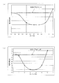
- the horizontal axis represents the ratio (D1 / D2) of the groove width D1 to the groove interval D2 of the trailing edge horizontal groove 5, and the vertical axis represents the noise effect.
- the groove width D1 of the trailing edge horizontal groove 5 is larger than the groove interval D2 (D1 / D2 ⁇ 1.0)
- a large amount of air flow flows into the groove recess 5a, and the air flow along the surface of the inter-groove surface portion 6 Decrease. For this reason, an unstable region is formed in another region of the surface of the blade outer peripheral surface 4c.
- the groove width D1 has a relationship of at least “0.5 ⁇ D2 ⁇ D1 ⁇ 1.0 ⁇ D2” with respect to the groove interval D2. Then, the low noise turbo fan 1 and the indoor unit 100 can be obtained.
- the horizontal axis represents the ratio (D1 / H) of the groove width D1 to the fan height H
- the vertical axis represents the noise effect. That is, if the ratio (D1 / H) is too small, the air flow does not enter the trailing edge horizontal groove 5, so that the noise effect is deteriorated (a high positive value). On the contrary, if the ratio (D1 / H) is too large, the air flow excessively flows in, so that the rectifying effect is lost and noise is generated. Therefore. There is an optimum range in the relationship between the groove width D1 and the fan blowout height H. Therefore, as shown in FIG. 9B, the ratio (D1 / H) is preferably set to “2 to 5%”.
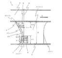
- the inter-groove surface portion 6 is an inter-groove continuous surface 6a that is a surface continuous with the blade outer peripheral surface 4c, and the inter-groove convex portion 6b that protrudes to the outer peripheral side in a predetermined range near the end of the blade trailing edge 4b. And have.
- the length L4 of the inter-groove convex portion 6b of the inter-groove surface portion 6 formed at the predetermined height is different from the length L4 of the inter-groove convex portion 6b of the inter-groove surface portion 6 adjacent in the vertical direction. is doing.
- the thickness of the groove recess 5 a of the trailing edge horizontal groove 5 is substantially the same as the thickness of the central portion (having a cavity) of the blade 4. For this reason, the depth (the amount of depression) of the groove recess 5a becomes shallower (less) as it approaches the blade trailing edge 4b.
- the depth (dent amount) of the groove recess 5a of the trailing edge horizontal groove 5 is substantially constant. For this reason, the thinner the groove recess 5a is, the closer it is to the blade trailing edge 4b.
- a groove-shaped recess (hereinafter referred to as “negative pressure side groove recess”) 5c reaching the groove communication portion 5b is formed on the blade inner peripheral surface 4d. Therefore, in cooperation with the groove recess 5a formed on the blade inner peripheral surface 4d, the above-mentioned effect is promoted.
- turbo fans and various forms of air (not limited to a ceiling-embedded type) equipped with the turbo fans are provided. It can be widely used as an indoor unit for a harmonic machine.
Landscapes
- Engineering & Computer Science (AREA)
- Mechanical Engineering (AREA)
- General Engineering & Computer Science (AREA)
- Structures Of Non-Positive Displacement Pumps (AREA)
Priority Applications (4)
| Application Number | Priority Date | Filing Date | Title |
|---|---|---|---|
| CN201180016013.2A CN102822532B (zh) | 2010-03-29 | 2011-03-24 | 涡轮风扇以及安装了该涡轮风扇的空调装置的室内机 |
| ES11762195T ES2747983T3 (es) | 2010-03-29 | 2011-03-24 | Turboventilador y aparato de aire acondicionado interior equipado el mismo |
| EP11762195.3A EP2554850B1 (en) | 2010-03-29 | 2011-03-24 | Turbofan and indoor air conditioner equipped with same |
| US13/582,933 US9267511B2 (en) | 2010-03-29 | 2011-03-24 | Turbofan and indoor unit of air-conditioning apparatus including the same |
Applications Claiming Priority (2)
| Application Number | Priority Date | Filing Date | Title |
|---|---|---|---|
| JP2010074052A JP5143173B2 (ja) | 2010-03-29 | 2010-03-29 | ターボファン及びこれを装備した空気調和機の室内機 |
| JP2010-074052 | 2010-03-29 |
Publications (1)
| Publication Number | Publication Date |
|---|---|
| WO2011121943A1 true WO2011121943A1 (ja) | 2011-10-06 |
Family
ID=44711710
Family Applications (1)
| Application Number | Title | Priority Date | Filing Date |
|---|---|---|---|
| PCT/JP2011/001718 WO2011121943A1 (ja) | 2010-03-29 | 2011-03-24 | ターボファン及びこれを装備した空気調和機の室内機 |
Country Status (6)
| Country | Link |
|---|---|
| US (1) | US9267511B2 (zh) |
| EP (1) | EP2554850B1 (zh) |
| JP (1) | JP5143173B2 (zh) |
| CN (1) | CN102822532B (zh) |
| ES (1) | ES2747983T3 (zh) |
| WO (1) | WO2011121943A1 (zh) |
Cited By (4)
| Publication number | Priority date | Publication date | Assignee | Title |
|---|---|---|---|---|
| WO2019021391A1 (ja) * | 2017-07-26 | 2019-01-31 | 三菱電機株式会社 | 空気調和機 |
| JPWO2018216085A1 (ja) * | 2017-05-22 | 2019-11-07 | 三菱電機株式会社 | 空気調和機 |
| TWI712357B (zh) * | 2015-01-08 | 2020-12-01 | 日商山洋電氣股份有限公司 | 風扇殼及風扇裝置 |
| EP3896289A1 (en) * | 2020-04-17 | 2021-10-20 | Sunonwealth Electric Machine Industry Co., Ltd. | Impeller and centrifugal fan including the same |
Families Citing this family (14)
| Publication number | Priority date | Publication date | Assignee | Title |
|---|---|---|---|---|
| JP6078945B2 (ja) * | 2011-11-04 | 2017-02-15 | ダイキン工業株式会社 | 遠心送風機 |
| KR20140125522A (ko) * | 2013-04-19 | 2014-10-29 | 엘지전자 주식회사 | 터보팬 |
| EP2829733B1 (en) | 2013-05-10 | 2021-01-27 | Lg Electronics Inc. | Centrifugal fan |
| KR101677030B1 (ko) | 2013-05-10 | 2016-11-17 | 엘지전자 주식회사 | 원심팬 |
| CN104251231A (zh) * | 2013-06-28 | 2014-12-31 | 苏州宝时得电动工具有限公司 | 离心式叶轮及包括该离心式叶轮的吹吸装置 |
| CN110985445B (zh) * | 2013-12-04 | 2021-03-30 | 松下知识产权经营株式会社 | 风机和装载有该风机的室外单元 |
| EP3214317B1 (en) * | 2014-10-30 | 2021-12-08 | Mitsubishi Electric Corporation | Turbofan, and indoor unit for air conditioning device |
| CN104763652A (zh) * | 2015-02-04 | 2015-07-08 | 张宏松 | 一种卧式鼓风机 |
| JPWO2018016012A1 (ja) * | 2016-07-19 | 2019-02-28 | 三菱電機株式会社 | 熱源機及び冷凍サイクル装置 |
| DE112017005519T5 (de) | 2016-11-01 | 2019-08-08 | Ihi Corporation | Variable Düseneinheit und Turbolader |
| JP7207933B2 (ja) * | 2018-10-15 | 2023-01-18 | 日立建機株式会社 | 建設機械 |
| EP3647603A1 (en) | 2018-10-31 | 2020-05-06 | Carrier Corporation | Arrangement of centrifugal impeller of a fan for reducing noise |
| DE102019121448A1 (de) * | 2019-08-08 | 2021-02-11 | Ebm-Papst Mulfingen Gmbh & Co. Kg | Radialgebläse für einen Dunstabzug |
| CN111043079A (zh) * | 2019-12-31 | 2020-04-21 | 潍柴动力股份有限公司 | 一种风扇叶片及风扇 |
Citations (4)
| Publication number | Priority date | Publication date | Assignee | Title |
|---|---|---|---|---|
| JPH09126190A (ja) | 1995-10-30 | 1997-05-13 | Sanyo Electric Co Ltd | 遠心式送風機 |
| JP2669448B2 (ja) | 1993-06-15 | 1997-10-27 | 松下冷機株式会社 | 遠心送風機の羽根車 |
| JP3092554B2 (ja) | 1997-09-30 | 2000-09-25 | ダイキン工業株式会社 | 遠心送風機及びその製造方法並びに該遠心送風機を備えた空気調和機 |
| JP2007292053A (ja) * | 2006-03-31 | 2007-11-08 | Daikin Ind Ltd | 多翼ファン |
Family Cites Families (5)
| Publication number | Priority date | Publication date | Assignee | Title |
|---|---|---|---|---|
| GB8829792D0 (en) * | 1988-12-21 | 1989-07-05 | Marconi Co Ltd | Noise reduction method |
| KR20040104772A (ko) * | 2003-06-03 | 2004-12-13 | 삼성전자주식회사 | 터보팬 및 이를 갖춘 공기조화기 |
| JP2006002691A (ja) * | 2004-06-18 | 2006-01-05 | Calsonic Kansei Corp | 送風機 |
| JP2007247492A (ja) * | 2006-03-15 | 2007-09-27 | Matsushita Electric Ind Co Ltd | 電動送風機およびそれを用いた電気掃除機 |
| KR20080045568A (ko) * | 2006-11-20 | 2008-05-23 | 삼성전자주식회사 | 터보팬 및 이를 갖춘 공기조화기 |
-
2010
- 2010-03-29 JP JP2010074052A patent/JP5143173B2/ja active Active
-
2011
- 2011-03-24 ES ES11762195T patent/ES2747983T3/es active Active
- 2011-03-24 CN CN201180016013.2A patent/CN102822532B/zh active Active
- 2011-03-24 EP EP11762195.3A patent/EP2554850B1/en active Active
- 2011-03-24 WO PCT/JP2011/001718 patent/WO2011121943A1/ja active Application Filing
- 2011-03-24 US US13/582,933 patent/US9267511B2/en active Active
Patent Citations (4)
| Publication number | Priority date | Publication date | Assignee | Title |
|---|---|---|---|---|
| JP2669448B2 (ja) | 1993-06-15 | 1997-10-27 | 松下冷機株式会社 | 遠心送風機の羽根車 |
| JPH09126190A (ja) | 1995-10-30 | 1997-05-13 | Sanyo Electric Co Ltd | 遠心式送風機 |
| JP3092554B2 (ja) | 1997-09-30 | 2000-09-25 | ダイキン工業株式会社 | 遠心送風機及びその製造方法並びに該遠心送風機を備えた空気調和機 |
| JP2007292053A (ja) * | 2006-03-31 | 2007-11-08 | Daikin Ind Ltd | 多翼ファン |
Non-Patent Citations (1)
| Title |
|---|
| See also references of EP2554850A4 * |
Cited By (9)
| Publication number | Priority date | Publication date | Assignee | Title |
|---|---|---|---|---|
| TWI712357B (zh) * | 2015-01-08 | 2020-12-01 | 日商山洋電氣股份有限公司 | 風扇殼及風扇裝置 |
| JPWO2018216085A1 (ja) * | 2017-05-22 | 2019-11-07 | 三菱電機株式会社 | 空気調和機 |
| US11397022B2 (en) | 2017-05-22 | 2022-07-26 | Mitsubishi Electric Corporation | Air conditioner |
| WO2019021391A1 (ja) * | 2017-07-26 | 2019-01-31 | 三菱電機株式会社 | 空気調和機 |
| TWI664381B (zh) * | 2017-07-26 | 2019-07-01 | 日商三菱電機股份有限公司 | 空氣調節機 |
| JPWO2019021391A1 (ja) * | 2017-07-26 | 2019-11-07 | 三菱電機株式会社 | 空気調和機 |
| CN110892201A (zh) * | 2017-07-26 | 2020-03-17 | 三菱电机株式会社 | 空气调节机 |
| CN110892201B (zh) * | 2017-07-26 | 2021-05-11 | 三菱电机株式会社 | 空气调节机 |
| EP3896289A1 (en) * | 2020-04-17 | 2021-10-20 | Sunonwealth Electric Machine Industry Co., Ltd. | Impeller and centrifugal fan including the same |
Also Published As
| Publication number | Publication date |
|---|---|
| EP2554850B1 (en) | 2019-08-28 |
| US9267511B2 (en) | 2016-02-23 |
| EP2554850A4 (en) | 2016-05-11 |
| JP2011208501A (ja) | 2011-10-20 |
| CN102822532A (zh) | 2012-12-12 |
| EP2554850A1 (en) | 2013-02-06 |
| CN102822532B (zh) | 2016-02-17 |
| JP5143173B2 (ja) | 2013-02-13 |
| ES2747983T3 (es) | 2020-03-12 |
| US20120328420A1 (en) | 2012-12-27 |
Similar Documents
| Publication | Publication Date | Title |
|---|---|---|
| JP5143173B2 (ja) | ターボファン及びこれを装備した空気調和機の室内機 | |
| JP5955402B2 (ja) | ターボファンおよび空気調和機 | |
| EP2264320B1 (en) | Turbofan and air conditioner | |
| JP3268279B2 (ja) | 空気調和機 | |
| JP5029577B2 (ja) | 空気調和機の室内機 | |
| JP2010133254A (ja) | 遠心送風機及びこれを備えた空気調和機 | |
| JP4859204B2 (ja) | 遠心ファンとそれを備えた空気調和装置 | |
| WO2017042926A1 (ja) | 空気調和機 | |
| JP6078945B2 (ja) | 遠心送風機 | |
| JP2006258344A (ja) | 空気調和機 | |
| WO2007119532A1 (ja) | ターボファン及び空気調和機 | |
| WO2020148905A1 (ja) | 送風装置 | |
| JP2001159396A (ja) | 遠心ファン及び該遠心ファンを備えた空気調和機 | |
| JP4371171B2 (ja) | クロスフローファン及びこれを備えた空気調和機 | |
| JPH0593523A (ja) | 空気調和装置 | |
| JP5609498B2 (ja) | 空気調和機の室内機 | |
| JP3488126B2 (ja) | エアカ−テン | |
| JP4274229B2 (ja) | 空気調和機 | |
| JP2016003641A (ja) | 遠心ファン | |
| JP3719368B2 (ja) | 送風機 | |
| JPH10160200A (ja) | 空気調和機用室外機 | |
| JP4687741B2 (ja) | 空気調和機 | |
| JP2017145738A (ja) | 送風装置 | |
| JP2000146214A (ja) | 空気調和機 | |
| JPH0422172Y2 (zh) |
Legal Events
| Date | Code | Title | Description |
|---|---|---|---|
| WWE | Wipo information: entry into national phase |
Ref document number: 201180016013.2 Country of ref document: CN |
|
| 121 | Ep: the epo has been informed by wipo that ep was designated in this application |
Ref document number: 11762195 Country of ref document: EP Kind code of ref document: A1 |
|
| WWE | Wipo information: entry into national phase |
Ref document number: 2011762195 Country of ref document: EP |
|
| WWE | Wipo information: entry into national phase |
Ref document number: 13582933 Country of ref document: US |
|
| NENP | Non-entry into the national phase |
Ref country code: DE |