WO2011121874A1 - エンドキャップ及びモール - Google Patents
エンドキャップ及びモール Download PDFInfo
- Publication number
- WO2011121874A1 WO2011121874A1 PCT/JP2011/000597 JP2011000597W WO2011121874A1 WO 2011121874 A1 WO2011121874 A1 WO 2011121874A1 JP 2011000597 W JP2011000597 W JP 2011000597W WO 2011121874 A1 WO2011121874 A1 WO 2011121874A1
- Authority
- WO
- WIPO (PCT)
- Prior art keywords
- molding
- rib
- clip
- main body
- end cap
- Prior art date
- Legal status (The legal status is an assumption and is not a legal conclusion. Google has not performed a legal analysis and makes no representation as to the accuracy of the status listed.)
- Ceased
Links
Images


Classifications
-
- B—PERFORMING OPERATIONS; TRANSPORTING
- B60—VEHICLES IN GENERAL
- B60J—WINDOWS, WINDSCREENS, NON-FIXED ROOFS, DOORS, OR SIMILAR DEVICES FOR VEHICLES; REMOVABLE EXTERNAL PROTECTIVE COVERINGS SPECIALLY ADAPTED FOR VEHICLES
- B60J10/00—Sealing arrangements
- B60J10/70—Sealing arrangements specially adapted for windows or windscreens
- B60J10/74—Sealing arrangements specially adapted for windows or windscreens for sliding window panes, e.g. sash guides
- B60J10/75—Sealing arrangements specially adapted for windows or windscreens for sliding window panes, e.g. sash guides for sealing the lower part of the panes
Definitions
- the present invention relates to an end cap attached to an end portion of a molding body. More specifically, the present invention relates to an end cap that is attached to a vehicle body together with the molding body by pressing a clip protruding from the opening of the molding body from the outer surface of the molding body immediately above and locking it to the vehicle body.
- the present invention also relates to a molding comprising an end cap attached to the molding body.
- a structure for mounting the molding (mall main body + end cap) to the outer panel for example, a structure described in Japanese Patent No. 4292932 (Patent Document 1) can be exemplified.
- “having an opening in a cross section” means that the shape of the cross section is a shape in which a part of the ring is missing and the lacking portion is formed as an opening. , J, V, k "and the like.
- the lower end of the lid 30 may protrude from the right end of the outer panel 70.
- the above-described minute deformation cannot be prevented, and the upper edge portion of the outer panel 70 corresponding to the minute deformation portion (upper edge portion near the door end)
- An object of the present invention is to prevent the above-mentioned poor appearance.
- the insertion portion 40 includes a vertical plate portion 45 having an insertion sliding contact surface 451 that is in sliding contact with a guide surface 571 in the molding main body 5 when inserted into the molding main body 5, and a lateral end where the base end portion 4701 of the rib 470 is continuous.
- the vertical plate portion 45 has an edge 452 that abuts against the inner surface of the wall portion 55 on the side opposite to the opening of the molding body 5 and is pressed when the clip 20 is locked via the molding body 5.
- the rib 470 is located on the vehicle outer side than a virtual plane 45p including the vertical plate portion 45; An end cap 1 characterized by that.
- the insertion portion 40 is provided so as to protrude from an insertion sliding contact surface 451 that is in sliding contact with the guide surface 571 in the molding main body 5 when inserted into the molding main body 5, and a notch 570 provided in the guiding surface 571. And has a locking part 450 that is inserted and locked by the elasticity of the insertion part 40,
- the rib 470 is a plate-like rib having a plate surface 4703 along the insertion direction, and the insertion-direction tip portion 4704 of the plate-like rib 470 is positioned in front of the locking portion 450 in the insertion direction.
- An end cap 1 characterized by that.
- Configuration 4 A molding comprising the end cap 1 of any one of configurations 1 to 3, and a molding body 5 to which the end cap 1 is attached.
- the configuration 1 is attached to an end of the molding body 5 having an opening 51 in a cross section, and the clip 20 protruding from the opening 51 of the molding body 5 is pressed through the molding body 5 to be locked to the vehicle body 70. Accordingly, the end cap 1 is attached to the vehicle body 70 together with the molding main body 5, and the lid portion 30 that covers the end of the molding main body 5 while being attached to the molding main body 5 and the base end portion 401 are the lid portion.
- An insertion portion 40 that is connected to the inner surface of the molding body 30 and inserted into the molding body 5 from the distal end portion 402; and a clip that is provided in the insertion section 40 so as to protrude from the opening 51 of the molding body 5 and that passes through the molding body 5
- the end cap 1 has a rib 470 that receives a reaction force from the vehicle body 70 when the distal end portion 4702 comes into contact with the vehicle body 70 by the pressing force at the time of 20 locking, the clip 20 is attached to the vehicle body.
- the lid 30 protrudes from the edge of the vehicle body 70 due to a dimensional accuracy error of the member, and the tip of the rib 470 is caused by the above pressing force.
- the rib 470 When the portion 4702 comes into contact with the vehicle body 70, the rib 470 receives a reaction force from the vehicle body 70 and supports the pressed portion and its vicinity. For this reason, the said site
- transformation ( falling) to a press direction, and generation
- the insertion portion 40 includes a vertical plate portion 45 having an insertion sliding contact surface 451 that comes into sliding contact with a guide surface 571 in the molding main body 5 when inserted into the molding main body 5, and a base end portion of the rib 470.
- the vertical plate portion 45 has an edge 452 abutting against the inner surface of the wall portion 55 on the side opposite to the opening of the molding body 5, and the clip 20 via the molding body 5. Since the rib 470 is an end cap 1 located outside the virtual plane 45p including the vertical plate portion 45, the rib 470 is provided to receive a pressing force at the time of stopping. In addition, there is an effect that the sealing force is not adversely affected by the pressing force at the time of mounting the mall.
- Configuration 3 is that in Configuration 1 or Configuration 2, the insertion portion 40 is provided so as to protrude from an insertion sliding contact surface 451 that is in sliding contact with the guide surface 571 in the molding main body 5 when being inserted into the molding main body 5.
- the notch 570 provided in the guide surface 571 has a locking portion 450 fitted and locked by the elasticity of the insertion portion 40
- the rib 470 has a plate surface 4703 along the insertion direction. Since it is a plate-shaped rib and the insertion direction front-end
- the rib 470 can reliably prevent the insertion portion 40 from being prevented from being inserted into the molding body 5. That is, the insertion portion 40 (45) is deformed by being pushed by the sliding contact guide surface 571 of the molding body 5 prior to the engagement portion 450 being fitted into the notch portion 570, but before that, the rib 470 Since the insertion direction front end portion 4704 is inserted into the molding body 5, it is possible to reliably prevent the rib 470 from interfering with the insertion of the insertion portion 40.
- the configuration 4 is a molding comprising the end cap 1 of any one of the configurations 1 to 3 and the molding main body 5 to which the end cap 1 is attached. Therefore, the molding that provides the operational effects of the configurations 1 to 3 is provided. can do.
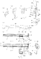
- FIG. 1A is a perspective view from the back side
- FIG. 1B is a perspective view from above (above when mounted on the vehicle body)
- FIG. 1C is an end surface along the line CC in FIG.
- (D) is an end view of line DD in (a)
- (e) is an end view of line EE in (a)
- (f) is an end view of line FF in (a)
- (g) is an end view taken along the line GG in (a)
- (h) is an end view taken along the line HH in (a)
- (i) is a view seen through the right side of (a).
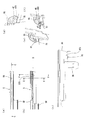
- (A) and (b) show the vicinity of the end of the molding body to which the end cap of FIG. 1 is mounted
- (a) is a plan view (viewed from above when mounted on the vehicle body)
- (b) is a rear view. is there.
- (C) to (f) show a state in which the end cap of FIG.
- FIGS. 3 (a) and 3 (b) are attached to the end of the molding body of FIGS. 3 (a) and 3 (b), (c) is a sectional view taken along the line CC in (a), (D) is a view taken in the interior D of (b), (e) is a sectional view taken along line EE in (b), and (f) is a sectional view taken along line FF in (b).
- (A) is a figure which shows the general cross section of the molding main body of FIG. 3 (a), (b), (b) is explanatory drawing which shows the molding mounting part of a motor vehicle.
- FIG. 4A shows a general cross section (a cross section of a normal portion excluding an end portion) of the molding body 5, 58 is an upper lip, and 59 is a lower lip. Since the general cross section of the molding body 5 is known, further description is omitted.
- the end cap 1 is attached to an end portion of the molding body 5 having an opening in a cross section, and imparts designability to the external appearance.
- the clip 20 provided on the end cap 1 projects downward from the opening 51 of the molding body 5.
- the clip 20 is moved downward from the outer surface (upper surface) side of the wall portion (top wall portion) 55 which is a portion (opposite opening portion side) opposite to the opening portion 51 of the molding body 5 through the wall portion 55.
- the end cap 1 is attached to the vehicle body (outer panel) 70 together with the molding body 5.
- “upper” and “lower” are definitions based on “upper” and “lower” when mounted on the vehicle body.
- the cross section of the molding body 5 has an opening
- the cross section of the molding body 5 has a ring shape as shown in FIGS. 2 (d) to (f) and FIGS. 3 (d) to (f)”. Is a shape in which a part of the defect is formed and the defect is formed as an opening.
- the cross-sectional shape can be represented by characters such as “C, U, J, V, and K”. .
- the end cap 1 has a lid portion 30 and an insertion portion 40.
- the lid portion 30 is a portion that covers the end portion of the molding body 5 so as not to be exposed.
- the insertion portion 40 is a portion that is inserted into the interior of the molding body 5.
- the locking portion 450 provided on the insertion portion 40 supports the locking portion 450. Due to the elasticity of the vertical plate portion 45 of the insertion portion 40, the insertion portion 40 is fitted into the notch portion 570 (FIG. 3B) provided in the corresponding portion of the molding body 5 (FIG. 3F). As a result, the end cap 1 is locked to the molding main body 5 to be in a mounted state, thereby forming an integral molding.
- Reference numeral 401 denotes a proximal end portion of the insertion portion 40.
- the engaging portion 450 is fitted into the cutout portion 570 so that the engaging portion 450 protrudes from the insertion sliding contact surface 451 of the elastic vertical plate portion 45 having elasticity. Is inserted into the molding body 5, the insertion sliding contact surface 451 is guided while being in sliding contact with the guide surface 571 of the molding body 5. In other words, the vertical plate portion 45 is deformed by being pushed by the locking portion 450 protruding from the insertion sliding contact surface 451, and the vertical plate portion 45 is elastically pushed back to resist the deformation.
- the gap is formed by connecting the vertical plate portion 45 and the horizontal plate portion 47 through the lid portion 30 on the lid portion 30 side, and the vertical plate portion 45 at the position of the clip 20 on the clip 20 side. Since the horizontal plate portion 47 is directly connected, it exists only between the clip 20 and the lid portion 30. That is, in front of the clip 20 (near the distal end portion 402 of the insertion portion 40), the vertical plate portion 45 and the horizontal plate portion 47 are continuously provided without a gap.
- a plate-like rib 470 is continuously provided from the horizontal plate portion 47 so that the plate surface 4703 is along the insertion direction.
- the lower end portion (tip portion) 4702 of the plate-like rib 470 is pressed when a pressing force is applied from the side of the wall portion (eg, the top wall portion) 55 on the side opposite to the opening portion to lock the clip 20 to the outer panel 70.
- the lower end side of the lid portion 30 protrudes from the right edge of the outer panel 70 due to, for example, an accuracy error of the member, it is provided so as to contact the upper surface of the outer panel 70.
- the front end portion 4702 of the plate-like rib 470 and the upper surface of the corresponding portion of the outer panel 70 are opposed to each other with a minute clearance.
- the plate-like rib 470 When the lower end portion (tip portion) 4702 of the plate-like rib 470 comes into contact with the upper surface of the outer panel 70 as described above, the plate-like rib 470 receives a reaction force from the outer panel 70 side and receives the molding (the molding body 5. Push back the end cap 1). For this reason, the molding does not deform due to the pressing force when trying to lock the clip 20, and therefore, even if there is an accuracy error of the above-described member, the molding between the lid portion 30 of the end cap 1 and the clip 20. In addition, the corresponding portion of the outer panel 70 is not fitted, and appearance defects are prevented.
- the pressing force Fa applied to the top wall portion 55 which is the wall portion on the side opposite to the opening when the clip 20 is locked is one edge portion (upper edge portion).
- the virtual plane 45p including the vertical plate portion 45 received at 452 and the virtual plane 470p including the plate-like rib 470 receiving the reaction force Fb exerted by the outer panel 70 against the pressing force Fa are slightly shifted from each other. Is provided. For this reason, a rotational force acts on the molding. That is, a force in the direction approaching the vehicle body (arrow c) acts on the upper side of the molding, and a force in the direction away from the vehicle body (arrow d) acts on the lower side of the molding. . As a result, the upper part in contact with the glass is more strongly pressed toward the glass side, and the pressing force when the clip 20 is attached is prevented from adversely affecting the sealing performance.
- the insertion direction front end portion 4704 of the plate-like rib 470 is more forward than the locking portion 450 by the length indicated by “t” in the drawing. Is provided. For this reason, before the locking portion 450 reaches the sliding contact guide surface 571 of the molding body 5, the insertion direction front end portion 4704 of the plate-like rib 470 is inserted into the molding body 5. In other words, the plate-like rib 470 is inserted into the molding body 5 before the locking plate 450 is pushed by the sliding contact guide surface 571 and the vertical plate portion 45 supporting the locking portion 450 starts to deform. Will be started. For this reason, the trouble that the plate-like rib 470 is caught at the end of the molding body 5 and the insertion of the end cap 1 into the molding body 5 is prevented.
Landscapes
- Engineering & Computer Science (AREA)
- Mechanical Engineering (AREA)
- Vehicle Interior And Exterior Ornaments, Soundproofing, And Insulation (AREA)
- Seal Device For Vehicle (AREA)
- Connection Of Plates (AREA)
Abstract
Description
また、本発明は、エンドキャップをモール本体に装着して成るモールに関する。
一方、何れかが、設計図の寸法から若干外れてしまっている場合もあり、その結果、図3(c)とは異なり、蓋体30の下端がアウタパネル70の右端からはみ出ている場合もある。
そのような場合には、上述の微小変形を防止することができず、当該の微小変形部位に対応するアウタパネル70の上縁の部位(ドア端部寄りの上縁部位)が、エンドキャップ30の蓋体下部の内側とクリップ20の縁部との間に嵌まり込み、上記の微小変形を固定して、モール端部に外観不良を生じ易いという不具合がある。
本発明は、上記の外観不良を防止することを目的とする。
断面に開口部51を有するモール本体5の端部に装着され、モール本体5の前記開口部51から突出するクリップ20をモール本体5を介して押圧して車体70に係止することにより、モール本体5とともに車体70に装着されるエンドキャップ1であって、
モール本体5に装着された状態でモール本体5の端部を覆う蓋部30と、
基端部401が前記蓋部30の内面に連なり先端部402からモール本体5内へ挿入される挿入部40と、
モール本体5の前記開口部51から突出するように前記挿入部40に設けられ、前記モール本体5を介するクリップ20係止時の押圧力により先端部4702が車体70に当接した場合に車体70からの反力を受けるリブ470と、
を有することを特徴とするエンドキャップ1。
構成1に於いて、
前記挿入部40は、モール本体5内への挿入時に該モール本体5内の案内面571と摺接する挿入摺接面451を有する縦板部45と、前記リブ470の基端部4701が連なる横板部47とを有し、前記縦板部45はその一縁部452がモール本体5の反開口部側の壁部55内面に当接して前記モール本体5を介するクリップ20係止時の押圧力を受けるように設けられ、前記リブ470は前記縦板部45が含まれる仮想平面45pより車外側に位置する、
ことを特徴とするエンドキャップ1。
構成1又は構成2に於いて、
前記挿入部40は、モール本体5内への挿入時に該モール本体5内の案内面571と摺接する挿入摺接面451から突出するように設けられ、前記案内面571に設けられた切欠部570に、当該挿入部40の弾力により嵌入されて係止される係止部450を有し、
前記リブ470は挿入方向に沿う板面4703を有する板状リブであり、該板状リブ470の挿入方向先端部4704は前記係止部450より挿入方向前方に位置する、
ことを特徴とするエンドキャップ1。
構成1~構成3の何れかのエンドキャップ1と、該エンドキャップ1が装着されたモール本体5と、から成るモール。
なお、モール本体5にエンドキャップ1を装着して成るモールは、図4(b)に例示するように、アウタパネル70の上縁部分に装着される。また、図4(a)はモール本体5の一般断面(端部等を除く通常の部分の断面)を示し、58は上リップ、59は下リップである。モール本体5の一般断面は公知であるため、これ以上の説明は省略する。
ここで、「上」「下」とは車体へ装着した状態での「上」「下」を基準とする定義である。また、「モール本体5の断面が開口部を有する」とは、「モール本体5の断面が、図2(d)~(f)や図3(d)~(f)に示すように、環の一部を欠損して該欠損部分を開口部と成した形状であることをいい、例えば、断面形状を「C、U、J、V、コ」等の文字で表し得るようなことをいう。
20 クリップ
30 蓋部
40 挿入部
401 挿入部の基端部
402 挿入部の先端部
45 縦板部
45p 縦板部が含まれる仮想平面
450 係止部
451 挿入摺接面
452 縦板部の一縁部
47 横板部
470 リブ
470p リブが含まれる仮想平面
4701 リブの基端部
4702 リブの先端部
4703 リブの板面(挿入方向に沿う)
4704 リブの挿入方向先端部
5 モール本体
51 開口部
55 (反開口部側の)壁部(天壁部)
570 切欠部
571 (摺接の)案内面
58 上リップ
59 下リップ
70 アウタパネル
Claims (4)
- 断面に開口部を有するモール本体の端部に装着され、モール本体の前記開口部から突出するクリップをモール本体を介して押圧して車体に係止することにより、モール本体とともに車体に装着されるエンドキャップであって、
モール本体に装着された状態でモール本体の端部を覆う蓋部と、
基端部が前記蓋部の内面に連なり先端部からモール本体内へ挿入される挿入部と、
モール本体の前記開口部から突出するように前記挿入部に設けられ、前記モール本体を介するクリップ係止時の押圧力により先端部が車体に当接した場合に車体からの反力を受けるリブと、
を有することを特徴とするエンドキャップ。 - 請求項1に於いて、
前記挿入部は、モール本体内への挿入時に該モール本体内の案内面と摺接する挿入摺接面を有する縦板部と、前記リブの基端部が連なる横板部とを有し、前記縦板部はその一縁部がモール本体の反開口部側の壁部内面に当接して前記モール本体を介するクリップ係止時の押圧力を受けるように設けられ、前記リブは前記縦板部が含まれる仮想平面より車外側に位置する、
ことを特徴とするエンドキャップ。 - 請求項1又は請求項2に於いて、
前記挿入部は、モール本体内への挿入時に該モール本体内の案内面と摺接する挿入摺接面から突出するように設けられ、前記案内面に設けられた切欠部に、当該挿入部の弾力により嵌入されて係止される係止部を有し、
前記リブは挿入方向に沿う板面を有する板状リブであり、該板状リブの挿入方向先端部は前記係止部より挿入方向前方に位置する、
ことを特徴とするエンドキャップ。 - 請求項1~請求項3の何れかのエンドキャップと、該エンドキャップが装着されたモール本体と、から成るモール。
Priority Applications (2)
| Application Number | Priority Date | Filing Date | Title |
|---|---|---|---|
| US13/634,865 US8578677B2 (en) | 2010-03-30 | 2011-02-03 | End cap and molding |
| CN201180017880.8A CN102834300B (zh) | 2010-03-30 | 2011-02-03 | 端盖和装饰嵌条 |
Applications Claiming Priority (2)
| Application Number | Priority Date | Filing Date | Title |
|---|---|---|---|
| JP2010-076716 | 2010-03-30 | ||
| JP2010076716A JP5355471B2 (ja) | 2010-03-30 | 2010-03-30 | エンドキャップ及びモール |
Publications (1)
| Publication Number | Publication Date |
|---|---|
| WO2011121874A1 true WO2011121874A1 (ja) | 2011-10-06 |
Family
ID=44711646
Family Applications (1)
| Application Number | Title | Priority Date | Filing Date |
|---|---|---|---|
| PCT/JP2011/000597 Ceased WO2011121874A1 (ja) | 2010-03-30 | 2011-02-03 | エンドキャップ及びモール |
Country Status (4)
| Country | Link |
|---|---|
| US (1) | US8578677B2 (ja) |
| JP (1) | JP5355471B2 (ja) |
| CN (1) | CN102834300B (ja) |
| WO (1) | WO2011121874A1 (ja) |
Cited By (1)
| Publication number | Priority date | Publication date | Assignee | Title |
|---|---|---|---|---|
| CN115822128A (zh) * | 2023-02-23 | 2023-03-21 | 成都建工第六建筑工程有限公司 | 一种装配式墙体构造和施工方法 |
Families Citing this family (9)
| Publication number | Priority date | Publication date | Assignee | Title |
|---|---|---|---|---|
| JP5965718B2 (ja) * | 2012-05-10 | 2016-08-10 | シロキ工業株式会社 | 車両ドア用ベルトモール |
| CN103568797B (zh) | 2012-08-01 | 2017-04-12 | 亨尼格斯汽车密封系统北美公司 | 用于密封配件的双端帽 |
| US8615962B1 (en) * | 2013-01-14 | 2013-12-31 | GM Global Technology Operations LLC | Retention feature for automotive deco trim |
| WO2017035492A1 (en) | 2015-08-26 | 2017-03-02 | Cooper-Standard Automotive Inc. | End cap clip lock |
| WO2018116443A1 (ja) * | 2016-12-22 | 2018-06-28 | 株式会社島津製作所 | 質量分析装置及び質量分析装置用プログラム |
| CN109849634B (zh) * | 2017-11-30 | 2021-11-26 | 长城汽车股份有限公司 | 水切端头安装结构和车辆 |
| JP7290334B2 (ja) * | 2020-06-19 | 2023-06-13 | 片山工業株式会社 | ベルトラインモール及びその端末保持構造 |
| JP7406515B2 (ja) | 2021-02-04 | 2023-12-27 | 東海興業株式会社 | ベルトモール及びその製造方法 |
| JP7605728B2 (ja) * | 2021-12-21 | 2024-12-24 | 東海興業株式会社 | ベルトモールの製造方法 |
Citations (4)
| Publication number | Priority date | Publication date | Assignee | Title |
|---|---|---|---|---|
| JP2001063365A (ja) * | 1999-08-31 | 2001-03-13 | Togo Seisakusho Corp | モール用クリップ |
| JP2004249745A (ja) * | 2003-02-18 | 2004-09-09 | Shiroki Corp | モールディング及びその製造方法 |
| JP2006069229A (ja) * | 2004-08-31 | 2006-03-16 | Kinugawa Rubber Ind Co Ltd | モールディングのエンドキャップ取付構造 |
| JP4292932B2 (ja) * | 2003-09-26 | 2009-07-08 | アイシン精機株式会社 | モールエンドキャップ |
Family Cites Families (3)
| Publication number | Priority date | Publication date | Assignee | Title |
|---|---|---|---|---|
| EP1795399B1 (en) * | 2004-10-01 | 2011-09-28 | Aisin Seiki Kabushiki Kaisha | Mould end cap |
| JP4235655B2 (ja) * | 2006-04-27 | 2009-03-11 | アイシン精機株式会社 | ベルトモール |
| JP4357545B2 (ja) * | 2007-05-28 | 2009-11-04 | 片山工業株式会社 | 自動車用モール及びその取り付け構造 |
-
2010
- 2010-03-30 JP JP2010076716A patent/JP5355471B2/ja active Active
-
2011
- 2011-02-03 CN CN201180017880.8A patent/CN102834300B/zh not_active Expired - Fee Related
- 2011-02-03 WO PCT/JP2011/000597 patent/WO2011121874A1/ja not_active Ceased
- 2011-02-03 US US13/634,865 patent/US8578677B2/en not_active Expired - Fee Related
Patent Citations (4)
| Publication number | Priority date | Publication date | Assignee | Title |
|---|---|---|---|---|
| JP2001063365A (ja) * | 1999-08-31 | 2001-03-13 | Togo Seisakusho Corp | モール用クリップ |
| JP2004249745A (ja) * | 2003-02-18 | 2004-09-09 | Shiroki Corp | モールディング及びその製造方法 |
| JP4292932B2 (ja) * | 2003-09-26 | 2009-07-08 | アイシン精機株式会社 | モールエンドキャップ |
| JP2006069229A (ja) * | 2004-08-31 | 2006-03-16 | Kinugawa Rubber Ind Co Ltd | モールディングのエンドキャップ取付構造 |
Cited By (1)
| Publication number | Priority date | Publication date | Assignee | Title |
|---|---|---|---|---|
| CN115822128A (zh) * | 2023-02-23 | 2023-03-21 | 成都建工第六建筑工程有限公司 | 一种装配式墙体构造和施工方法 |
Also Published As
| Publication number | Publication date |
|---|---|
| CN102834300B (zh) | 2015-01-21 |
| JP5355471B2 (ja) | 2013-11-27 |
| US8578677B2 (en) | 2013-11-12 |
| US20130008123A1 (en) | 2013-01-10 |
| CN102834300A (zh) | 2012-12-19 |
| JP2011207333A (ja) | 2011-10-20 |
Similar Documents
| Publication | Publication Date | Title |
|---|---|---|
| JP5355471B2 (ja) | エンドキャップ及びモール | |
| JP5805942B2 (ja) | 車両ドア用ベルトモール | |
| CN107614326A (zh) | 车载用电子设备的盖 | |
| JP5682228B2 (ja) | 電気接続箱 | |
| JP2007290667A (ja) | ベルトモール | |
| JPWO2012043147A1 (ja) | 車両用カウルトップ位置決め構造 | |
| JP2017087854A (ja) | 車両用サイドドア | |
| JP2010007283A (ja) | 戸車レールの清掃装置 | |
| US9688218B2 (en) | Frame molding for vehicle door | |
| CN105358379A (zh) | 车辆用密封构造 | |
| US8769782B2 (en) | Resin molded parts lock mechanism | |
| JP5151630B2 (ja) | 車両用サイドミラー | |
| JP2014228112A (ja) | 取付部材の取付構造 | |
| US12109979B2 (en) | Locking device for opening/closing body | |
| GB2458002A (en) | Easily detachable connector | |
| JP5781360B2 (ja) | コントロールケーブルの端末固定装置 | |
| JP2007168636A (ja) | バンパ取付用ブラケット | |
| JP5173470B2 (ja) | 電気接続箱の取付構造 | |
| CN211417143U (zh) | 一种汽车三角饰板卡接安装结构 | |
| JP2010023737A (ja) | ベルトモールの取付構造 | |
| JP6111115B2 (ja) | 車両用ドアガラスシール構造 | |
| JP2017001489A (ja) | モール | |
| JP2006051906A (ja) | 車両用の飾り縁部材 | |
| JP4861720B2 (ja) | ドアモール用クリップ | |
| JP6141706B2 (ja) | 車両用キャリアプレートの取付構造 |
Legal Events
| Date | Code | Title | Description |
|---|---|---|---|
| WWE | Wipo information: entry into national phase |
Ref document number: 201180017880.8 Country of ref document: CN |
|
| 121 | Ep: the epo has been informed by wipo that ep was designated in this application |
Ref document number: 11762129 Country of ref document: EP Kind code of ref document: A1 |
|
| WWE | Wipo information: entry into national phase |
Ref document number: 13634865 Country of ref document: US |
|
| NENP | Non-entry into the national phase |
Ref country code: DE |
|
| 122 | Ep: pct application non-entry in european phase |
Ref document number: 11762129 Country of ref document: EP Kind code of ref document: A1 |