WO2011121735A1 - 貨幣移送システム、貨幣移送システムの貨幣移送方法及び貨幣処理装置用搬送カセット - Google Patents
貨幣移送システム、貨幣移送システムの貨幣移送方法及び貨幣処理装置用搬送カセット Download PDFInfo
- Publication number
- WO2011121735A1 WO2011121735A1 PCT/JP2010/055725 JP2010055725W WO2011121735A1 WO 2011121735 A1 WO2011121735 A1 WO 2011121735A1 JP 2010055725 W JP2010055725 W JP 2010055725W WO 2011121735 A1 WO2011121735 A1 WO 2011121735A1
- Authority
- WO
- WIPO (PCT)
- Prior art keywords
- money
- transfer
- destination
- information
- transport cassette
- Prior art date
Links
Images


Classifications
-
- G—PHYSICS
- G07—CHECKING-DEVICES
- G07F—COIN-FREED OR LIKE APPARATUS
- G07F19/00—Complete banking systems; Coded card-freed arrangements adapted for dispensing or receiving monies or the like and posting such transactions to existing accounts, e.g. automatic teller machines
- G07F19/20—Automatic teller machines [ATMs]
- G07F19/202—Depositing operations within ATMs
-
- G—PHYSICS
- G07—CHECKING-DEVICES
- G07D—HANDLING OF COINS OR VALUABLE PAPERS, e.g. TESTING, SORTING BY DENOMINATIONS, COUNTING, DISPENSING, CHANGING OR DEPOSITING
- G07D11/00—Devices accepting coins; Devices accepting, dispensing, sorting or counting valuable papers
- G07D11/0087—Banknote changing devices
-
- G—PHYSICS
- G07—CHECKING-DEVICES
- G07D—HANDLING OF COINS OR VALUABLE PAPERS, e.g. TESTING, SORTING BY DENOMINATIONS, COUNTING, DISPENSING, CHANGING OR DEPOSITING
- G07D11/00—Devices accepting coins; Devices accepting, dispensing, sorting or counting valuable papers
- G07D11/10—Mechanical details
- G07D11/12—Containers for valuable papers
- G07D11/125—Secure containers
-
- G—PHYSICS
- G07—CHECKING-DEVICES
- G07D—HANDLING OF COINS OR VALUABLE PAPERS, e.g. TESTING, SORTING BY DENOMINATIONS, COUNTING, DISPENSING, CHANGING OR DEPOSITING
- G07D11/00—Devices accepting coins; Devices accepting, dispensing, sorting or counting valuable papers
- G07D11/20—Controlling or monitoring the operation of devices; Data handling
- G07D11/24—Managing the stock of valuable papers
- G07D11/245—Replenishment
-
- G—PHYSICS
- G07—CHECKING-DEVICES
- G07D—HANDLING OF COINS OR VALUABLE PAPERS, e.g. TESTING, SORTING BY DENOMINATIONS, COUNTING, DISPENSING, CHANGING OR DEPOSITING
- G07D11/00—Devices accepting coins; Devices accepting, dispensing, sorting or counting valuable papers
- G07D11/50—Sorting or counting valuable papers
-
- G—PHYSICS
- G07—CHECKING-DEVICES
- G07D—HANDLING OF COINS OR VALUABLE PAPERS, e.g. TESTING, SORTING BY DENOMINATIONS, COUNTING, DISPENSING, CHANGING OR DEPOSITING
- G07D7/00—Testing specially adapted to determine the identity or genuineness of valuable papers or for segregating those which are unacceptable, e.g. banknotes that are alien to a currency
- G07D7/181—Testing mechanical properties or condition, e.g. wear or tear
-
- G—PHYSICS
- G07—CHECKING-DEVICES
- G07F—COIN-FREED OR LIKE APPARATUS
- G07F9/00—Details other than those peculiar to special kinds or types of apparatus
- G07F9/02—Devices for alarm or indication, e.g. when empty; Advertising arrangements in coin-freed apparatus
Definitions
- the present invention relates to a money transfer system for transferring money between a transfer source money processing device and a transfer destination money processing device, for example, between a change machine and a cashier in a store, a money transfer method for a money transfer system, and a transfer for a money processing device.
- cassettes for transferring money between a transfer source money processing device and a transfer destination money processing device, for example, between a change machine and a cashier in a store.
- change machines such as coin depositing and dispensing machines and banknote depositing and dispensing machines have been connected to cash registers such as POS (Point Of Sales) registers at retail stores such as supermarkets and convenience stores and service stores such as restaurants.
- POS Point Of Sales
- a system is known (see, for example, Patent Document 1).
- the withdrawal by the bank account transaction function and the loan by the lending service can be dispensed to the customer.
- the merchandise cash transaction function corresponds to a cash settlement function that pays the merchandise price in cash when the merchandise is purchased.
- the bank account transaction function when paying for the product price at the same time withdrawing or lending a deposit account, the price obtained by subtracting the product price from the withdrawal amount or loan amount without throwing out the withdrawal or loan to the outside.
- a change machine equipped with a bank account transaction function for example, when a 30,000 yen deposit is withdrawn from a deposit account at the same time as purchasing a 5000 yen product, a cash-out amount of 25,000 is deducted from the withdrawal amount of 30,000 yen. Yen yen to customers.
- Patent Document 1 since the bank account transaction function is used and the cash-out amount obtained by subtracting the product price from the withdrawal amount of the deposit account when the product is purchased, the customer can withdraw the deposit while Part of the withdrawal amount can be used for the product price.
- a change machine one having a function of recirculating and using a part of a deposited banknote as a change banknote is known (for example, see Patent Document 2).
- the change machine identifies the deposited banknote and stores the deposited banknote in the stacker when the deposited banknote is a correct one.
- a change machine accommodates the deposit banknote in a rejection accommodating part, when the deposit banknote is a damage ticket with a high damage degree.
- Patent Document 2 based on the identification result of the deposited banknote, when the deposited banknote is a genuine note, the deposited banknote can be used as a change banknote, and when the deposited banknote is a non-performing banknote, the deposited banknote can be collected. .
- the depositing machine arranged in the distribution store has functions such as banknote deposit processing and change processing such as change (see, for example, Patent Document 3). Further, the teller machine collects the sales proceeds in the store through the deposit process. The in-store sales collected by the cashier is transferred to the cash processing center by a cash delivery company entrusted with the collection operation.
- a function of identifying the correct / incorrect classification of banknotes and sorting and storing them into correct banknotes and non-performing banknotes based on the identification result is known (for example, Patent Documents). 4).
- the correct banknote is used as a withdrawal banknote, the damaged banknote is collected, and the diversion as a withdrawal banknote is prohibited.
- Japanese Patent Laid-Open No. 11-250350 see abstract and paragraphs 0024 to 0049
- Japanese Patent No. 3295288 see claim 1 and FIG. 2
- Japanese Patent No. 3983992 see paragraph 0040 and FIG. 2
- Japanese Patent No. 3805458 (refer to claim 1, paragraph 0037 and FIG. 1)
- JP-A-2005-275804 (refer to claim 1 and FIG. 1)
- the present invention has been made in view of the above points, and the object of the present invention is to transfer money that can greatly reduce the processing burden on the transfer destination side of money identification even when the transfer of money from the transfer source to the transfer destination.
- a system, a money transfer method of a money transfer system, and a transport cassette for a money handling apparatus are provided.
- the money transfer system of the present invention is detachable with respect to a transfer destination money processing device, a transfer source money processing device, both the transfer destination money processing device and the transfer source money processing device, A money transfer system having a transfer cassette for storing money to be transferred from the transfer source money processing device to the transfer destination money processing device, wherein the denomination of the money and the correct / incorrect classification of the correct and non-performing bills Based on the identification unit on the transfer source money processing apparatus side for identifying the classification and the identification result of the identification unit, storage breakdown information for managing the denomination and damage classification for each currency stored in the transport cassette is created.
- An information creation unit on the transfer source money processing device side a notification unit that notifies the transfer destination money processing device of the storage breakdown information of the transport cassette created by the information creation unit, and the communication
- a recognition unit on the transfer destination money processing apparatus side that recognizes the denomination and damage classification of each money stored in the transport cassette based on the storage breakdown information And to have.
- the storage breakdown information includes storage position identification information for identifying the storage position of the money in order to identify the money stored in the transport cassette.
- the storage breakdown information includes serial number information of the money in order to identify the money stored in the transport cassette.
- the transport cassette has at least two storage units that are stored separately for a specific denomination of genuine bills and non-use bills.
- the notifying unit transmits the storage breakdown information of the transport cassette to the transfer destination money processing device via a network that connects the transfer destination money processing device and the transfer source money processing device. To be notified.
- the notifying unit notifies the transfer destination money processing apparatus of the storage breakdown information of the transport cassette via the storage medium that stores the storage breakdown information provided in the transport cassette. I did it.
- the transfer destination money processing device corresponds to a cashier in the store
- the transfer source money processing device corresponds to a change machine in the store.
- a money transfer method of a money transfer system includes a transfer destination money processing device, a transfer source money processing device, and both the transfer destination money processing device and the transfer source money processing device.
- a money transfer method of a money transfer system that is detachable and has a transport cassette for storing money to be transferred from the transfer source money processing device to the transfer destination money processing device, comprising: And an identification step on the transfer source money processing device side for identifying a damage category for classifying a damage ticket, and a denomination category and an impairment category for each currency stored in the transport cassette based on the identification result of the identification step
- Information generation step on the transfer source money processing apparatus side for generating storage breakdown information for managing the storage breakdown information, and the storage breakdown information of the transport cassette generated by the information generation step
- the money transport system of the present invention is detachable from the transfer destination money processing apparatus, the transfer source money processing apparatus, and both the transfer destination money processing apparatus and the transfer source money processing apparatus,
- a money transfer system having a transport cassette for storing money to be transferred from an apparatus to the destination money handling apparatus, wherein the transfer identifies a denomination of the money and a new and old classification for distinguishing a new ticket and an old ticket
- the transfer source money processing apparatus that creates storage breakdown information for managing the denomination and old and new classifications of each money stored in the transport cassette
- the information generation unit on the side, a notification unit for notifying the storage breakdown information of the transport cassette generated by the information generation unit to the destination money handling apparatus, and the notification unit
- a recognizing unit on the transfer destination money processing apparatus side for recognizing the denomination and the old and new classification of each money stored in the transport cassette based on the storage breakdown information. did.
- the transport cassette for a money handling device transfers a mounting interface that can be attached to and detached from both the transfer destination money processing device and the transfer source money processing device, and transfers the transfer money from the transfer source money processing device to the transfer destination money processing device. It has at least two storage units for storing money of a specific denomination separately into regular bills and non-performing bills.
- the money transfer system of the present invention can be attached to and detached from a transfer destination money processing device, a transfer source money processing device, and both the transfer destination money processing device and the transfer source money processing device.
- a money transfer system having a transfer cassette for storing money to be transferred to the transfer destination money processing device, wherein the amount information of money held for each denomination and damage category managed by the transfer destination money processing device.
- the transfer for calculating the replenishment breakdown number of the money to be replenished to the transfer destination money processing device based on the transfer information of the transfer source money processing device to be acquired and the transfer information of the transfer destination money processing device
- the transfer source that stores the money to be replenished in the transfer destination money processing device in the transport cassette based on the breakdown calculation unit on the source money processing device side and the replenishment breakdown number calculated by the breakdown calculation unit And to a control unit of the bill processing apparatus.
- the breakdown calculation unit calculates the replenishment breakdown number of money to be replenished to the transfer destination money processing apparatus based on the presence or absence of the cashout function of the transfer destination money processing apparatus.
- the money transfer system is based on an identification unit on the side of the source money processing device that identifies a denomination of money and a correct / incorrect classification that separates a correct bill and a non-performing bill, and an identification result of the identification unit.
- An information creation unit on the transfer source money processing device side that creates storage breakdown information for managing denominations and damage categories for each currency stored in the transport cassette, and the transport created by the information creation unit When the storage breakdown information notified by the notification unit and the storage breakdown information notified by the notification unit are acquired, the storage breakdown information of the cassette is stored in the transfer cassette.
- a recognition unit on the transfer destination money processing apparatus side for recognizing the denomination of money and the damage classification.
- the transfer destination money processing device corresponds to a change machine in a store
- the transfer source money processing device corresponds to a cashier in the store.
- the money transfer method of the money transfer system of the present invention includes a transfer destination money processing device, a transfer source money processing device, and can be attached to and detached from both the transfer destination money processing device and the transfer source money processing device.
- the amount information acquisition step on the side of the source money processing device for acquiring information on the amount of money held by the transfer source money processing device, and the amount of the money to be replenished to the destination money processing device based on the amount information of the destination money processing device
- the transfer destination money processing apparatus is replenished.
- the money was to include a control step of the migration source money handling apparatus for storing into the transport cassette.
- the storage breakdown information of the transport cassette is created on the transfer source money processing apparatus side, and the storage breakdown information of the created transport cassette is notified to the transfer destination money processing apparatus. . Furthermore, in the money transfer system of the present invention, when the storage breakdown information is acquired on the transfer destination money processing apparatus side, the denomination and the damage classification of each money stored in the transport cassette are recognized based on the storage breakdown information. . As a result, the transfer destination money processing device can recognize the denomination and damage classification of each currency without identifying each money stored in the transport cassette, greatly reducing the processing burden required for that identification. There is an effect that can be done.
- the storage position identification information is included in the storage breakdown information to identify the money, so the transfer destination money processing device identifies the money in the transport cassette based on the storage position identification information. There is an effect that can be done.
- the serial number information is included in the storage breakdown information to identify the money, so that the transfer destination money processing apparatus can identify the money in the transport cassette based on the serial number information. There is an effect.
- the transport cassette since the transport cassette has at least two storage units, there is an effect that it is possible to distinguish and store a genuine denomination and a non-performing bill of a specific denomination.
- the storage breakdown information of the transport cassette is notified to the transfer destination money processing apparatus via the network, so that the transfer destination money processing apparatus can acquire the storage breakdown information of the transfer cassette. Play.
- the transfer destination money processing apparatus can acquire the storage breakdown information of the transfer cassette. Play.
- the storage breakdown information of the transport cassette is created on the change machine side, and the storage breakdown information of the created transport cassette is notified to the teller machine. Furthermore, in the money transfer system according to the present invention, when the storage breakdown information is acquired on the cashier side, the denomination and damage classification of each money stored in the transport cassette is recognized based on the storage breakdown information. As a result, since the teller machine can recognize the denomination and damage classification of each currency without identifying each currency stored in the transport cassette, the processing load required for the identification can be greatly reduced. Play.
- the storage breakdown information of the transport cassette is created on the transfer source money processing apparatus side, and the storage breakdown information of the transport cassette thus created is transferred to the destination money processing. Notify the device. Further, in the money transfer method of the present invention, when the storage breakdown information is acquired on the transfer destination money processing apparatus side, the denomination and the damage classification of each money stored in the transport cassette are recognized based on the storage breakdown information. . As a result, the transfer destination money processing device can recognize the denomination and damage classification of each currency without identifying each money stored in the transport cassette, greatly reducing the processing burden required for that identification. There is an effect that can be done.
- the storage breakdown information of the transport cassette is created on the transfer source money processing apparatus side, and the storage breakdown information of the created transfer cassette is notified to the transfer destination money processing apparatus. Furthermore, in the money transfer system of the present invention, when the storage breakdown information is acquired on the transfer destination money processing apparatus side, the denomination and the old and new classification of each money stored in the transport cassette are recognized based on the storage breakdown information. As a result, the transfer destination money processing apparatus can recognize the denominations and old and new classifications of each currency without identifying each money stored in the transport cassette, thereby greatly reducing the processing burden required for the identification. There is an effect.
- the money handling apparatus transport cassette according to the present invention, it is possible to attach and detach to both the transfer destination money processing apparatus and the transfer source money processing apparatus, and to transfer the specific denomination to be transferred from the transfer source money processing apparatus to the transfer destination money processing apparatus. There is an effect that money can be stored separately in a regular bill and a non-paid bill.
- the replenishment breakdown number of money to be replenished to the transfer destination money processing apparatus is calculated based on the acquired amount information. Furthermore, in the money transfer system of the present invention, money to be replenished to the destination money handling apparatus is stored in the transport cassette based on the calculated number of replenishment of money. As a result, the transfer source money processing apparatus can automatically store the number of replenishment breakdowns for each denomination and damage category that should be supplied to the transfer destination money processing apparatus in the transport cassette.
- the replenishment breakdown number of money to be replenished to the transfer destination money processing apparatus is calculated based on the presence or absence of the cashout function of the transfer destination money processing apparatus, Considering the presence or absence of the cash-out function, the effect of recognizing the presence or absence of replenishment of genuine bills is achieved.
- the storage breakdown information of the transfer cassette storing the replenishment money is created on the transfer source money processing apparatus side, and the storage breakdown information of the created transfer cassette is notified to the transfer destination money processing apparatus. Furthermore, in the money transfer system of the present invention, when the storage breakdown information is acquired on the transfer destination money processing device side, the denomination and the damage classification of each supplementary money stored in the transport cassette are recognized based on the storage breakdown information. To do. As a result, the transfer destination money processing device can recognize the denomination and damage classification of each currency without identifying each supplementary money stored in the transport cassette, greatly increasing the processing burden required for the identification. There is an effect that it can be reduced.
- the money transfer system of the present invention when the amount information of the change machine as a transfer destination is acquired, the number of replenishment breakdowns of money to be replenished to the change machine is calculated based on the acquired amount information. Furthermore, in the money transfer system of the present invention, money to be replenished to the change machine is stored in the transport cassette based on the calculated number of replenishment of money. As a result, there is an effect that the teller machine which is a transfer source can automatically store the replenishment breakdown amount of money for each denomination and damage category to be replenished in the change machine in the transport cassette.
- the replenishment breakdown number of money to be replenished to the transfer destination money processing apparatus is calculated based on the acquired amount information.
- money to be replenished to the destination money handling apparatus is stored in the transport cassette based on the calculated number of replenishment of money.
- the transfer source money processing apparatus can automatically store the number of replenishment breakdowns for each denomination and damage category that should be supplied to the transfer destination money processing apparatus in the transport cassette.
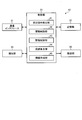
- FIG. 1 is a block diagram illustrating the configuration of the in-store funds management system according to the first embodiment.
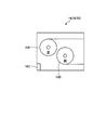
- FIG. 2 is an explanatory diagram showing the internal configuration of the banknote processing unit of the change machine.
- FIG. 3 is a block diagram showing the internal configuration of the change machine.
- FIG. 4 is an explanatory diagram showing service contents of the change machine.
- FIG. 5 is an explanatory diagram showing the internal configuration of the teller machine.
- FIG. 6 is a block diagram showing an internal configuration of the teller machine.
- FIG. 7 is an explanatory diagram showing the transfer relationship of the transfer cassette between the change machine and the teller machine.
- FIG. 8 is a flowchart showing the processing operation of the control unit of the change machine related to the change process.
- FIG. 8 is a flowchart showing the processing operation of the control unit of the change machine related to the change process.
- FIG. 9 is a flowchart showing the processing operation of the control unit of the teller machine related to the banknote replenishment process.
- FIG. 10 is a flowchart showing the processing operation of the control unit of the change machine related to the storage breakdown information storage processing.
- FIG. 11 is a flowchart showing the processing operation of the control unit of the teller machine related to the storage breakdown information acquisition processing.
- FIG. 12 is a block diagram illustrating an internal configuration of the change machine according to the second embodiment.
- FIG. 13 is a block diagram illustrating an internal configuration of the teller machine according to the second embodiment.
- FIG. 14 is a flowchart showing the processing operation of the control unit of the teller machine related to the banknote replenishment process.
- FIG. 10 is a flowchart showing the processing operation of the control unit of the change machine related to the storage breakdown information storage processing.
- FIG. 11 is a flowchart showing the processing operation of the control unit of the teller machine related to the storage breakdown information acquisition processing.
- FIG. 12 is a block
- FIG. 15 is a flowchart showing the processing operation of the control unit of the teller machine related to the storage breakdown information storage processing.
- FIG. 16 is a flowchart showing the processing operation of the control unit of the change machine related to the storage breakdown information acquisition processing.
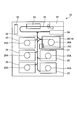
- FIG. 17 is an explanatory diagram showing the configuration inside the transport cassette.
- summary will use the conveyance cassette which can be attached or detached to both a transfer origin money processing apparatus and a transfer destination money processing apparatus, and the outline
- the banknotes are transferred to the processing apparatus, the storage breakdown information including the denominations and correctness classifications of the money stored in the transport cassette is notified to the transfer destination money processing apparatus.
- the transfer destination money processing device can recognize the denomination and damage classification of each currency without identifying each money stored in the transport cassette, greatly reducing the processing burden required for the identification. It can be done.
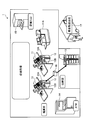
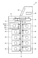
- FIG. 1 is a block diagram illustrating the configuration of the in-store funds management system according to the first embodiment.
- the in-store funds management system 1 shown in FIG. 1 includes a POS register 11, a change machine 12, a self-registration unit 11A, a cashier 13, an ATM machine 14, a collection machine 15, and a transport cassette 16.
- the POS register 11 is arranged at a checkout office, and corresponds to a face-to-face manned register that manages a customer's purchased product using the POS function and settles the product price of the purchased product.
- the change machine 12 is arranged adjacent to the POS register 11 and inserts the cash of the product amount settled by the POS register 11 or the like from the insertion port, and also dispenses the change money obtained by subtracting the cash input amount from the product amount from the outlet. .
- the change machine 12 has a banknote processing unit 12A for throwing out change bills of change money and a coin processing unit 12B for throwing out change coins of change money.
- the self-registration unit 11A is arranged at a checkout office, and is configured as an integrated system of the POS register 11, change machine 12, anti-fraud measuring device and the like so that the customer can make payments. This corresponds to an unattended settlement unit that manages the purchased product and settles the product price of the purchased product.
- the teller machine 13 manages the cash funds in the store according to denominations and losses through all the change machines 12 in the store.
- the ATM machine 14 corresponds to an automatic teller machine that provides bank services in the store.
- the collection machine 15 collects, for example, a customer's banknote banknotes arranged at the entrance of the store and returns the banknote banknotes of the same amount to the customer.
- the cash delivery company 17 collects, for example, sales proceeds from cash funds in the store managed by the cashier 13 in response to a delivery request from the store, and delivers the collected sales to a financial institution. .
- the cash delivery company 17 delivers a store operation reserve to the store according to the denomination and loss according to the delivery request from the store.
- FIG. 2 is an explanatory diagram showing an internal configuration of the banknote processing unit 12A of the change machine 12, and hereinafter, the banknote processing unit 12A will be described as the change machine 12.
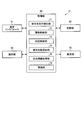
- FIG. 3 is a block diagram showing the internal configuration of the change machine 12.
- the change machine 12 shown in FIG. 2 includes an insertion port 21, a conveyance unit 22, an identification unit 23, a discharge port 24, a reflux stacker 25, a conveyance cassette 26, a reader / writer 27, and a control unit 33.
- the insertion slot 21 corresponds to an entrance for inserting banknotes into the change machine 12.
- the transport unit 22 is configured by a transport belt or the like, and transports banknotes on a transport path between the insertion port 21, the reflux stacker 25, the transport cassette 26, and the outlet 24.
- the branch part which is not illustrated is arrange
- the identification unit 23 is arranged on the conveyance path and identifies the type of the bill inserted from the insertion slot 21.
- banknote types for example, in the case of euro banknotes, in addition to the seven types of denominations of 5 euros, 10 euros, 20 euros, 50 euros, 100 euros, 200 euros and 500 euros, genuine and counterfeit tickets There is a true / false classification that identifies the correctness, and a correct / injured classification that identifies correct / lossy tickets.
- the damage classification is based on ECB regulations.
- the banknote type includes a front / back classification for identifying the front / back and a printing plate classification for identifying a new ticket / old ticket for each denomination.
- Reflux stacker 25 stores banknotes inserted from the insertion slot 21 for each designated denomination and feeds out the stored banknotes to the outlet 24.
- the reflux stacker 25 adopts a tape reel system and stores the banknotes in the reel 25A while winding the banknotes around the tape one by one. In the example of the change machine 12 shown in FIG. 2, a total of five reflux stackers 25 are provided.
- the transport cassette 26 includes a designated banknote collection unit 26A that collects designated banknotes to be collected, and an IC tag 16C that is attached to the cassette surface and stores storage breakdown information that will be described later.
- the designated banknote collection unit 26A employs a tape reel system.
- the dispensing outlet 24 throws out the banknotes thrown out from the reflux stacker 25 and, based on the identification result of the banknotes thrown out from the insertion slot 24, the banknotes to be rejected outside the change machine 12. Throw out.
- the reader / writer 27 reads / writes the storage breakdown information stored in the IC tag 16 ⁇ / b> C attached to the transport cassette 26.
- the change machine 12 shown in FIG. 3 includes a communication interface 31, a storage unit 32, and a control unit 33.
- the communication interface 31 is connected to the POS register 11 and is connected to the teller machine 13 via a network (not shown).
- the storage unit 32 stores and manages the storage position, denomination, and damage classification of each banknote stored in the reflux stacker 25 and the transport cassette 26 for each of the reflux stacker 25 and the transport cassette 26.
- storage part 32 memorize
- the control unit 33 includes a dispensing instruction detection unit 41, a drive control unit 42, a storage control unit 43, a change calculation unit 44, and an information creation unit 45.
- the throwing-in instruction detection unit 41 detects a bill throwing instruction corresponding to a transaction amount relating to a commodity cash transaction or a bill throwing instruction corresponding to a transaction amount relating to a bank account transaction.
- the merchandise cash transaction or the bank account transaction is activated in response to a predetermined operation of an operation unit (not shown).
- the change calculation unit 44 inputs cash into the insertion slot 21 at the time of purchasing a product, and calculates a change amount obtained by subtracting the product amount from the cash input amount.
- the service content of the change machine 12 will be described with reference to FIG.
- the change machine 12 throws out 80 euro change bills from the outlet 24 when the cash input amount is 100 euros and the merchandise amount is 20 euros. In this case, it may be a regular ticket or a non-performing ticket.
- the change calculation unit 44 calculates a cash-out amount obtained by subtracting a product amount from a withdrawal amount or a loan amount when purchasing a product at the time of a bank account transaction cash-out service. As shown in FIG.
- the change machine 12 when the change machine 12 makes a debit settlement with a withdrawal amount of 100 euros and a merchandise amount of 20 euros, the cash-out amount of 80 euros obtained by subtracting the merchandise amount from the withdrawal amount is a correct banknote. It will be thrown out from the outlet 24. As shown in FIG. 4 (C), for example, when the withdrawal amount is 100 euro as a withdrawal service, the change machine 12 throws out the withdrawal amount 24 as a correct bill with the withdrawal amount as 100 euro. .
- the drive control unit 42 When the drive control unit 42 detects an instruction to throw out banknotes corresponding to the transaction amount related to the bank account transaction, the drive control unit 42 throws out the correct banknote corresponding to the transaction amount stored in the reflux stacker 25 from the outlet 24. Therefore, the reflux stacker 25 and the transport unit 22 are driven and controlled. In bank account transactions, the bills are also thrown out in the withdrawal service, the loan service, and the cash-out service, so that the provisions of Article 6 of the ECB can be observed.
- the drive control unit 42 When the drive control unit 42 detects the instruction to throw out the change banknote corresponding to the transaction amount related to the product cash transaction, the drive control unit 42 throws out the banknote corresponding to the transaction amount stored in the reflux stacker 25 from the outlet 24. In order to take it out, the reflux stacker 25 and the conveyance unit 22 are driven and controlled.
- the storage control unit 43 based on the identification result of the identification unit 23, stores the banknotes inserted from the insertion port 21 in the reflux stacker 25 or the transport cassette 26, and denomination and correctness of the banknotes for each storage position.
- the classification is stored in the storage unit 32.
- the storage control unit 43 stores in the storage unit 32 current amount information for each denomination and loss type including the denominations and loss categories of all banknotes stored in the change machine 12.
- the information creation unit 45 stores the banknotes including the storage position, denomination classification, damage classification, and cash register number of each banknote stored in the transport cassette 26. Create information.
- the storage control unit 43 stores the storage breakdown information in an IC tag attached to the transport cassette 26.
- the reflux stacker 25 employs a tape reel system and stores bills of a designated denomination regardless of whether the damage is classified. Accordingly, it takes time to designate one of the designated denomination bill paper or the non-payment bill bill and feed it to the transport unit 22.
- 20 euro banknotes are stored in the return stacker 25 in the order of a non-illustrated non-illustrated storage opening in the order of a non-use ticket ⁇ correct note ⁇ correct note ⁇ correct note ⁇ strip note ⁇ .
- the drive control unit 42 feeds out the banknotes as the first banknote.
- the drive control unit 42 sequentially feeds the correct bills as the second to fifth bills, and sequentially transfers these correct bills to the other reflux stacker 25. Furthermore, the drive control part 42 pays out a total of two 20 euro banknotes as a sixth banknote. Therefore, it is necessary to pay out a total of six bills in order to pay out two 20 euro banknotes. In addition, since the four regular bills transferred to the other reflux stacker 25 need to be returned to the original reflux stacker 25, it takes time.
- the drive control unit 42 pays out the banknote banknotes from the reflux stacker 25 even when the banknotes corresponding to the change amount at the time of cash settlement stored in the reflux stacker 25 are preferentially thrown out from the outlet 24.
- the return stacker 25 and the conveyance unit 22 are driven and controlled so that the correct bills are thrown out from the outlet 24 instead of the damaged bills.
- the drive control unit 42 when it takes time to feed the banknote banknote from the reflux stacker 25 to the transport unit 22, instead of the banknote banknote, a low denomination of the same amount of the banknote banknote stored in the reflux stacker 25.
- the return stacker 25 and the conveyance unit 22 are driven and controlled to throw out the banknotes having the configuration from the outlet 24. For example, when a 40 euro banknote is thrown out, two 20 euro banknotes are covered with a normal denomination, but 10 euro is used for a low denomination banknote. It will be covered by the denomination of 4 bills, 1 20 euro bill and 2 10 euro bills.
- the drive control unit 42 instead of the correct bills, a low denomination of the same amount of the correct bills stored in the reflux stacker 25.
- the return stacker 25 and the transport unit 22 are driven and controlled to throw out the structured bills from the outlet 24.
- the drive control unit 42 does not change the input port for cash settlement even when the mode for preferentially throwing out the banknote corresponding to the change amount at the time of cash settlement stored in the reflux stacker 25 from the outlet 24 is set.
- the return stacker 25 and the stacker 25 in order to throw out the correct banknotes corresponding to the transaction amount related to the commodity cash transaction stored in the return stacker 25 from the outlet 24.
- the transport unit 22 is driven and controlled.
- the drive control unit 42 when designating the banknotes of the designated denomination as a collection target, in order to preferentially transport the banknotes stored in the reflux stacker 25 to the transport cassette 26, the reflux stacker 25.
- the conveyance unit 22 is driven and controlled.
- the drive control part 42 conveys a correct banknote preferentially to the conveyance cassette 26 from the banknote similarly accommodated in the recirculation
- the designated denomination may be a plurality of denominations.
- the drive control unit 42 preferentially supplies the specified number of banknotes of the specified denomination stored in the reflux stacker 25 to the transport cassette 26.
- the reflux stacker 25 and the transport unit 22 are driven and controlled to be transported.
- the drive control unit 42 preferentially sends the designated banknote of the designated denomination stored in the reflux stacker 25 to the transport cassette 26. Transport.
- the drive control unit 42 should preferentially convey the amount of the designated banknote stored in the reflux stacker 25 to the transport cassette 26.
- the reflux stacker 25 and the conveyance unit 22 are driven and controlled.
- the drive control unit 42 preferentially conveys the designated bills stored in the reflux stacker 25 to the transport cassette 26.
- the drive control unit 42 preferentially selects the excess banknote exceeding the designated total amount stored in the reflux stacker 25.
- the reflux stacker 25 and the transport unit 22 are driven and controlled to be transported to the transport cassette 26.
- the drive control unit 42 preferentially uses the excess correct banknote exceeding the designated total amount stored in the reflux stacker 25. To the transport cassette 26.
- the drive control unit 42 exceeds the specified number of specified denominations stored in the reflux stacker 25.
- the reflux stacker 25 and the conveyance unit 22 are driven and controlled.
- the drive control part 42 will specify the excess correct bill exceeding the designated number of the designated denomination accommodated in the reflux stacker 25, when the excess correct bill exceeding the designated number of money types specified as collection object is designated. The bill is preferentially conveyed to the conveyance cassette 26.
- the drive control unit 42 drives and controls the transport cassette 26 and the transport unit 22 so as to transport the banknotes stored in the transport cassette 26 to the outlet 24 and the reflux stacker 25.
- the control unit 33 designates a collection target to be conveyed to the conveyance cassette 26 by a designation operation of an operation unit (not shown) of the change machine 12 or the teller machine 13.
- the change machine 12 is provided with the function which gives a privilege point to a customer member card according to the number of correct bills, for example, when the inserted bills are correct bills when the bills are inserted into the insertion slot 21. Yes.
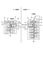
- FIG. 5 is an explanatory diagram showing the internal configuration of the teller machine 13
- FIG. 6 is a block diagram showing the internal configuration of the teller machine 13.
- the teller machine 13 shown in FIG. 5 includes an insertion port 51, a transport unit 52, an identification unit 53, a discharge port 54, a reflux stacker 55, a transport cassette 56 (16), a reader / writer 57, an operation / display unit 58, and a control unit 63.
- the insertion port 51 corresponds to an entrance for inserting banknotes into the teller machine 13.
- the transport unit 52 is configured by a transport belt or the like, and transports banknotes on a transport path between the insertion port 51, the reflux stacker 55, and the transport cassette 56.
- the branch part which is not illustrated is arrange
- the reflux stacker 55 stores the inserted banknote of the designated denomination inserted from the insertion port 51 and feeds it when the stored banknote is thrown into the outlet 54.
- the reflux stacker 55 employs a tape reel system.
- the transport cassette 56 includes the same type of loading interface as the transport cassette 26 of the change machine 12, and can be loaded and unloaded from the change machine 12 as well as the teller machine 13.
- the transport cassette 56 includes a designated banknote collection unit 56A that collects designated banknotes to be collected, and an IC tag 16C that is attached to the cassette surface and stores storage breakdown information that will be described later.
- the transfer cassette 26 of the change machine 12 has the same type of loading interface as the transfer cassette 56 and can be loaded and unloaded from the cashier 13.
- the reader / writer 57 reads / writes the storage breakdown information stored in the IC tag 16C attached to the transport cassette 56 (16).
- the operation / display unit 58 corresponds to a touch panel type operation / display unit, and inputs and displays various information.
- the communication interface 61 communicates with each change machine 12 via a network (not shown).
- the storage unit 62 stores and manages the storage position, denomination and damage classification of each banknote stored in the reflux stacker 55 and the transport cassette 56 for each reflux stacker 55 and transport cassette 56. Furthermore, the memory
- the control unit 63 identifies and manages each change machine 12 using the register number of the POS register 11 to which the change machine 12 is connected.
- the control unit 63 includes a replenishment destination instruction detection unit 71, a drive control unit 72, a storage control unit 73, a replenishment number calculation unit 74, a stock amount information acquisition unit 75, and a recognition unit 76.
- the replenishment destination instruction detection unit 71 designates a replenishment destination of banknotes to be replenished by the cashier 13, for example, a replenishment destination such as the change machine 12 or the ATM machine 14.
- the cash amount information acquisition unit 75 collects the current cash amount information of the denominations and damage categories of the change machines 12 and the ATM machines 14 via the communication interface 61 via the network. Further, the storage control unit 73 stores the collected current amount information of each change machine 12 and the ATM machine 14 in the storage unit 62. Further, when the transfer cassette 26 of the change machine 12 is loaded in the teller machine 13, the recognition unit 76 collects storage breakdown information through the IC tag 16 ⁇ / b> C of the transfer cassette 26. Further, the recognizing unit 76 recognizes the storage position, denomination and damage classification of each banknote stored in the transport cassette 26 without using the identification unit 53 based on the collected storage breakdown information.
- the replenishment destination instruction detection unit 71 When the replenishment number calculation unit 74 detects a replenishment instruction specifying the replenishment destination in the replenishment destination instruction detection unit 71, the replenishment destination instruction detection unit 71 performs the replenishment based on the current stock information of the replenishment destination and the ideal stock information of the replenishment destination The number of banknotes classified by denomination and loss that should be replenished first is calculated as the replenishment breakdown number. It is assumed that the control unit 63 stores and manages the ideal amount information and the like in the storage unit 62 for each replenishment destination. The ideal balance information of the replenishment destination corresponds to the number of banknotes classified by denomination and loss that should be held as the replenishment destination.
- the drive control unit 72 When the drive control unit 72 detects a replenishment instruction specifying the change machine 12 having a bank account transaction function as a replenishment destination, the drive control unit 72 determines the replenishment breakdown number of sheets stored in the reflux stacker 55 based on the calculation result of the replenishment number calculation unit 74.
- the return stacker 55 and the conveyance unit 52 are driven and controlled to throw out correct bills and damaged bills from the outlet 54.
- the drive control unit 72 does not throw out the replenishment breakdown number of correct banknotes and damaged banknotes to the outlet 54, and should transport the replenishment breakdown number of correct banknotes and damage banknotes to the transport cassette 56 as a collection target.
- the reflux stacker 55 and the conveyance unit 52 may be driven and controlled.
- the drive control unit 72 When the drive control unit 72 detects a replenishment instruction specifying the change machine 12 having no bank account transaction function as a replenishment destination, the loss of the replenishment breakdown number stored in the reflux stacker 55 based on the calculation result of the replenishment number calculation unit 74. In order to throw out the bills from the outlet 54, the reflux stacker 55 and the transport unit 52 are driven and controlled. In addition, although the banknote of the replenishment breakdown number was made into only a non-payment banknote, it is good also as a mixed banknote including only a genuine banknote or a genuine banknote. Further, the drive control unit 72 may drive-control the reflux stacker 55 and the conveyance unit 52 so that the replenishment breakdown number of banknotes is collected and conveyed to the conveyance cassette 56.
- the drive control unit 72 When the drive control unit 72 detects a replenishment instruction that designates the ATM machine 14 as the designated destination, based on the calculation result of the replenishment number calculation unit 74, the replenishment breakdown number of correct bills stored in the reflux stacker 55 is thrown out.
- the return stacker 55 and the transport unit 52 are driven and controlled so as to be thrown out from the printer.
- the drive control unit 72 may drive-control the reflux stacker 55 and the transport unit 52 so as to transport the replenishment breakdown number of bills to the transport cassette 56 as a collection target.
- the drive control unit 72 when it takes time to pay out the banknotes from the reflux stacker 55 to the transport unit 52, instead of the banknotes, a low denomination of the same amount of the banknotes stored in the reflux stacker 55.
- the return stacker 55 and the conveyance unit 52 are driven and controlled to throw out the banknotes having the configuration from the outlet 54. For example, when a 40 euro banknote is thrown out, two 20 euro banknotes are covered with a normal denomination, but 10 euro is used for a low denomination banknote. It will be covered by the denomination of 4 bills, 1 20 euro bill and 2 10 euro bills.
- the drive control unit 72 replaces the correct bill with a low denomination of the same amount of the correct bill stored in the reflux stacker 55.
- the return stacker 55 and the conveyance unit 52 are driven and controlled to throw out the structured bills from the outlet 54.
- the drive control unit 72 when designating the banknotes of the designated denomination as a collection target, in order to preferentially transport the banknotes stored in the reflux stacker 55 to the transport cassette 56, the transport stacker 55 and the transport The unit 52 is driven and controlled.
- the drive control unit 72 preferentially conveys the correct banknotes stored in the reflux stacker 55 to the transport cassette 56 when the correct denomination of correct banknotes is to be collected. Needless to say, a plurality of denominations may be designated.
- the drive control unit 72 designates the specified number of banknotes as the collection target
- the specified number of banknotes stored in the reflux stacker 55 is preferentially transported to the transport cassette 56. Therefore, the reflux stacker 55 and the conveyance unit 52 are driven and controlled.
- the drive control unit 72 preferentially sends the designated banknote of the designated denomination stored in the reflux stacker 55 to the transport cassette 56. Transport.
- the drive control unit 72 should preferentially transport the banknotes for the specified total amount stored in the reflux stacker 55 to the transport cassette 56.
- the reflux stacker 55 and the conveyance unit 52 are driven and controlled.
- the drive control unit 72 preferentially conveys the designated bills stored in the reflux stacker 55 to the transport cassette 56.
- the drive control unit 72 preferentially selects the excess banknote exceeding the specified total amount stored in the reflux stacker 55.
- the reflux stacker 55 and the transport unit 52 are driven and controlled to be transported to the transport cassette 56.
- the drive control unit 72 preferentially selects the excess correct banknote exceeding the specified total amount stored in the reflux stacker 55. To the transport cassette 56.
- the drive control unit 72 selects the excess denomination banknotes exceeding the designated number of denominations stored in the reflux stacker 55.
- the reflux stacker 55 and the transport unit 52 are driven and controlled to be transported preferentially to the transport cassette 56.
- the drive control unit 72 receives the excess bill paper money exceeding the designated money type number stored in the reflux stacker 55. It is preferentially transported to the transport cassette 56.
- the drive control unit 72 drives and controls the transport cassette 56 and the transport unit 52 in order to transport the banknotes stored in the transport cassette 56 to the outlet 54 and the reflux stacker 55.
- the control part 63 shall perform the designation
- FIG. 1
- FIG. 7 is an explanatory diagram showing the transfer relationship of the transport cassette 16 (26, 56) between the change machine 12 and the teller machine 13.
- the transfer cassette 26 of the change machine 12 can also be loaded and unloaded from the cashier 13.
- the transport cassette 56 of the cashier 13 can be loaded and unloaded from the change machine 12 as well.
- the information creation unit 45 of the change machine 12 includes the storage position, denomination classification, damage classification, and cash register number of each banknote stored in the transport cassette 26. Create storage breakdown information. After creating the storage breakdown information, the storage control unit 43 of the change machine 12 stores the storage breakdown information in the IC tag 16C attached to the transport cassette 26.
- the store clerk removes the transport cassette 26 from the change machine 12, and transports the transport cassette 26 to the cashier room. Then, the store clerk loads the transport cassette 26 into the teller machine 13. Then, when the transport cassette 26 is loaded, the recognition unit 76 of the teller machine 13 acquires storage breakdown information through the IC tag 16C of the transport cassette 26. Further, the recognizing unit 76 recognizes the storage position, denomination and damage classification of each banknote without identifying each banknote stored in the transport cassette 26 through the identification unit 53 based on the storage breakdown information. Further, the storage control unit 73 stores and manages the storage breakdown information in the storage unit 62.
- the collecting machine 15 is disposed at the store entrance or the like.
- the recovery machine 15 throws out the correct bill corresponding to the inserted amount from the outlet to the customer when the customer's banknote is inserted from the insertion slot. As a result, it is possible to increase the distribution ratio of the regular bills distributed in the store by suppressing the use of the banknotes by customers in the store.
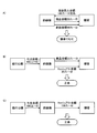
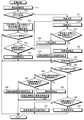
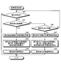
- FIG. 8 is a flowchart showing the processing operation of the control unit 33 of the change machine 12 related to the change process.
- the control unit 33 of the change machine 12 determines whether or not the payment method is debit settlement (step S12).
- the debit payment corresponds to a cash-out service for bank account transactions.
- the change calculation unit 44 of the control unit 33 determines the cash out amount by subtracting the product amount from the withdrawal amount or loan amount of the debit settlement (Step S13), and cash out It is determined whether there is a bill corresponding to the amount (step S13A).
- Step S13A When there is a banknote corresponding to the cash-out amount (Yes in Step S13A), the control unit 33 determines whether or not a correct banknote corresponding to the cash-out amount is in the reflux stacker 25 (Step S14). When the correct banknote corresponding to the cash-out amount is in the reflux stacker 25 (Yes in step S14), the control unit 33 throws out the correct banknote corresponding to the cash-out amount in the return stacker 25 from the outlet 24 (step S14). S15), the processing operation shown in FIG.
- the control unit 33 ends the processing operation shown in FIG.
- the control unit 33 has a low denomination type bill corresponding to the cash-out amount stored in the reflux stacker 25.
- the banknote is thrown out from the outlet 24 (step S16), and the processing operation shown in FIG.
- the control unit 33 determines that the payment is cash payment (Step S17) and detects the cash insertion from the insertion slot 21 (Step S18).
- the change calculation unit 44 of the control unit 33 determines whether or not there is a shortage by subtracting the product amount from the cash input amount (step S19).
- Step S19 When there is a shortage by subtracting the product amount from the cash input amount (Yes at Step S19), the control unit 33 notifies the shortage amount (Step S20) and waits for the cash input to the input port 21 at Step S18.
- notification may be made by display or voice.
- control unit 33 determines the change amount when the amount of merchandise is subtracted from the amount of cash input and there is no shortage (No at Step S19) (Step S21). When the change amount is confirmed, the control unit 33 determines whether there is a bill corresponding to the change amount (step S22). When there is a bill corresponding to the change amount (Yes at Step S22), the control unit 33 determines whether or not all inserted bills inserted into the insertion slot 21 are correct (Step S23).
- the control unit 33 determines whether there is a correct bill corresponding to the change amount in the return stacker 25 when all the inserted bills are correct (Yes in Step S23) (Step S24). When there is a correct bill corresponding to the change amount (Yes at Step S24), the control unit 33 throws out the correct bill corresponding to the change amount stored in the reflux stacker 25 from the outlet 24 (Step S25), FIG. The processing operation shown is terminated.
- the control unit 33 ends the processing operation illustrated in FIG.
- the control unit 33 determines whether or not there is a damaged banknote corresponding to the change amount in the reflux stacker 25 (Step S26).
- the control unit 33 throws out the banknote corresponding to the change amount stored in the reflux stacker 25 from the outlet 24 (step S27), as shown in FIG. The processing operation shown is terminated.
- step S26 when there is no change banknote corresponding to the change amount (No in step S26), the control unit 33 determines whether or not there is a low denomination type banknote corresponding to the change amount in the reflux stacker 25 (step S26). S28). When there is a low-value denominated bill banknote (Yes in step S28), the control unit 33 throws out the low-value denominated bill banknote stored in the reflux stacker 25 from the outlet 24 (step S29). The processing operation shown in FIG.
- control part 33 will not be limited to a banknote banknote, but the correct banknote corresponding to the banknote amount accommodated in the return stacker 25, when there is no banknote of the low money type structure corresponding to a banknote amount (No in step S28). A bill is thrown out from the outlet 24 (step S30), and the processing operation shown in FIG.
- control unit 33 is not limited to the correct bill, and the change amount corresponding to the change amount stored in the return stacker 25.
- the banknote is thrown out from the outlet 24 (step S31), and the processing operation shown in FIG.
- the change machine 12 can comply with the provisions of ECB Article 6.
- the change machine 12 can suppress the outflow of the correct bills and increase the number of stored correct bills in the device.
- the change machine 12 can provide the change with the correct bill to the customer who uses the correct bill for the cash settlement.
- FIG. 9 is a flowchart showing the processing operation of the control unit 63 of the teller machine 13 related to the banknote replenishment process.
- the replenishment destination instruction detection unit 71 of the control unit 63 shown in FIG. 9 determines whether or not a replenishment destination designation operation has been detected (step S41).
- the replenishment destination designation operation corresponds to a replenishment destination device identification number designation operation such as a registration number for identifying the replenishment destination change machine 12 or an ATM number for identifying the replenishment destination ATM machine 14.
- the control unit 63 detects a replenishment destination designation operation (Yes at Step S41), the control unit 63 determines whether or not the replenishment destination is the change machine 12 (Step S42).
- the control unit 63 acquires the current amount information and the ideal amount information of the replenishment destination change machine 12 from the storage unit 62 (Step S43).
- the replenishment number calculation unit 74 of the control unit 63 calculates the replenishment breakdown number for each denomination and deduction for the replenishment changer 12 based on the current and ideal stock information of the replenishment changer 12 ( Step S44).
- the control unit 63 throws out the calculated replenishment breakdown number of banknotes from the outlet 54 (step S45), and the processing operation shown in FIG.
- the control unit 63 determines whether or not the replenishment destination is the ATM machine 14 (Step S46).
- the control unit 63 acquires the current amount information and the ideal amount information of the replenishment destination ATM machine 14 from the storage unit 62 (Step S47).
- the replenishment number calculation unit 74 of the control unit 63 calculates the replenishment breakdown number for each denomination and deduction for the replenishment ATM machine 14 based on the current and ideal stock information of the replenishment destination ATM machine 14 ( Step S48).
- the control unit 63 throws out the calculated replenishment breakdown number of bills from the outlet 54 (step S49), and ends the processing operation shown in FIG.
- step S46 the control unit 63 proceeds to step S41 to determine whether or not a replenishment destination designation operation has been detected. Furthermore, when the replenishment destination instruction detection unit 71 does not detect the designation operation of the replenishment destination (No at Step S41), the processing operation illustrated in FIG.
- the replenishment breakdown by denomination of denominations to be replenished to the change machine 12 based on the current and ideal stock information of the replenishment change machine 12.
- the number of sheets is calculated, and the calculated replenishment number of banknotes is discharged from the outlet 54.
- the teller machine 13 can throw out the replenishment breakdown number of banknotes to be replenished to the replenishment change machine 12 from the outlet 54.
- the replenishment breakdown number (the number of regular tickets) of the money type to be replenished to the ATM machine 14 is calculated. Then, the calculated replenishment breakdown number of correct bills is thrown out from the outlet 54. As a result, the teller machine 13 can throw out the replenishment breakdown number of bills to be replenished from the replenishment ATM machine 14 from the outlet 54.
- FIG. 10 is a flowchart showing the processing operation of the control unit 33 of the change machine 12 related to the storage breakdown information storage processing.
- the control unit 33 of the change machine 12 shown in FIG. 10 determines whether or not a removal preparation operation for the transport cassette 26 has been detected (step S51).
- the control unit 33 acquires the storage position, denomination and damage classification of the banknotes stored in the transport cassette 26 from the storage unit 32.
- the information creation unit 45 of the control unit 33 creates a storage breakdown information by assigning a cash register number for identifying the change machine 12 to the storage position, denomination and damage classification of each acquired banknote (step S52). ).
- the storage control unit 43 of the control unit 33 stores the created storage breakdown information in the IC tag 16C of the transport cassette 26 (step S53), removes the transport cassette 26 from the change machine 12 (step S54), and is shown in FIG. The processing operation is terminated.
- the control unit 33 ends this processing operation when it does not detect the preparation for removing the transport cassette 26 (No in step S51).
- FIG. 11 is a flowchart showing the processing operation of the control unit 63 of the teller machine 13 related to the storage breakdown information acquisition processing.
- the control unit 63 shown in FIG. 11 determines whether or not the loading of the transport cassette 26 of the change machine 12 with respect to the cashier 13 is detected (step S61).
- the recognition unit 76 of the control unit 63 detects the loading of the transport cassette 26 (Yes in Step S61)
- the recognition unit 76 acquires the storage breakdown information through the IC tag 16C of the transport cassette 26 (Step S62).
- the storage control unit 73 of the control unit 63 stores the storage breakdown information in the storage unit 62 (step S63).
- the recognition unit 76 of the control unit 63 recognizes the storage position, denomination and damage classification of each banknote stored in the transport cassette 26 (step S64). The processing operation shown in FIG. In addition, when the loading of the transport cassette 26 of the change machine 12 to the teller machine 13 is not detected (No at Step S61), the control unit 63 ends the processing operation illustrated in FIG.
- the teller machine 13 can recognize the storage position, denomination and damage classification of each banknote stored in the transport cassette 26 without using the identification unit 53.
- the storage breakdown information of the transport cassette 16 (26, 56) is created on the change machine 12 side, and the storage breakdown information of the created transport cassette 16 (26, 56) is notified to the teller machine 13. Further, in the first embodiment, when the storage breakdown information is acquired on the cashier 13 side, the denomination and the damage classification of each banknote stored in the transport cassette 16 (26, 56) are recognized based on the storage breakdown information. To do. As a result, since the teller machine 13 can recognize the denomination and damage classification of each banknote without identifying each banknote stored in the transport cassette 16 (26, 56), the processing burden required for the identification Can be greatly reduced.
- the storage position identification information is included in the storage breakdown information to identify the banknotes in the transport cassette 16 (26, 56). 16 (26, 56) can be identified.
- the storage breakdown information of the transport cassette 16 (26, 56) is notified to the teller machine 13 via the IC tag 16C, so that the teller machine 13 stores the storage breakdown of the transport cassette 16 (26, 56). Information can be acquired.
- the identification unit 53 is not used in the machine.
- the denomination classification and the damage classification of the transported banknote can be recognized.
- the information creation unit 45 is built in the control unit 33 of the change machine 12, and the recognition unit 76 is built in the control unit 63 of the teller machine 13. Based on the storage breakdown information created on the change machine 12 side. The denomination and damage classification of each banknote in the transport cassette 16 is recognized on the cashier 13 side. However, on the basis of the storage breakdown information created on the cashier 13 side, the denomination and damage classification of each banknote in the transport cassette 16 may be recognized on the change machine 12 side. An embodiment in this case will be described below.
- FIG. 12 is a block diagram illustrating an internal configuration of the change machine 12 according to the second embodiment.
- the control unit 33 of the change machine 12 shown in FIG. 12 includes a recognition unit 46 in addition to a throwing instruction detection unit 41, a drive control unit 42, a storage control unit 43, a change calculation unit 44, and an information creation unit 45. Yes.
- the recognition unit 46 collects the storage breakdown information stored in the IC tag 16C of the transport cassette 16.
- the recognizing unit 46 can store the banknotes stored in the transport cassette 16 (26, 56) based on the collected storage breakdown information, the denomination classification, and the damage classification without using the identification unit 23. Recognize
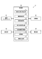
- FIG. 13 is a block diagram showing the internal configuration of the teller machine 13 according to the second embodiment.
- 13 includes a replenishment destination instruction detection unit 71, a drive control unit 72, a storage control unit 73, a replenishment number calculation unit 74, a stock information acquisition unit 75, and a recognition unit 76.
- An information creation unit 77 is included. When the banknote of the designated denomination is stored in the transport cassette 16 (26, 56), the information creation unit 77 stores the storage position, denomination, and correctness of each banknote stored in the transport cassette 16 (26, 56). The storage breakdown information including the classification and the replenishment destination identification number is created.
- the replenishment destination identification number corresponds to a cash register number when the replenishment destination is the change machine 12, and an ATM number when the replenishment destination is the ATM machine 14. Further, the storage control unit 73 stores the storage breakdown information in the IC tag 16C attached to the transport cassette 16 (26, 56).
- the information creation unit 77 of the teller machine 13 identifies the storage position, denomination, damage classification, and replenishment destination of each banknote stored in the transport cassette 56. Create storage breakdown information including numbers.
- the storage control unit 73 of the teller machine 13 creates the storage breakdown information, it stores the storage breakdown information in the IC tag 16C affixed to the transport cassette 56. Then, the store clerk removes the transport cassette 56 from the teller 13, and transports the transport cassette 56 to the checkout office. Then, the store clerk loads the transport cassette 56 into the change machine 12.
- the recognition unit 46 of the change machine 12 acquires storage breakdown information through the IC tag 16C of the transport cassette 56. Further, when the identification number of the replenishment destination in the storage breakdown information matches the cash register number of the change machine 12, the recognition unit 46 recognizes each banknote stored in the transport cassette 56 through the identification unit 23 based on the storage breakdown information. Even if it is not identified, the storage position, denomination classification and damage classification of each banknote are recognized. Further, the storage control unit 43 of the change machine 12 stores and manages the storage breakdown information in the storage unit 32.
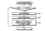
- FIG. 14 is a flowchart showing the processing operation of the control unit 63 of the teller machine 13 related to the banknote replenishment process.
- the replenishment number calculation unit 74 of the control unit 63 shown in FIG. 14 performs the processing of step S41 to step S43, to the replenishment change machine 12 based on the current and ideal stock information of the replenishment changer 12. Then, the replenishment breakdown number for each denomination is calculated (step S44).
- the control unit 63 stores the calculated replenishment breakdown number of banknotes in the transport cassette 56 (16) (step S45A) and ends the processing operation shown in FIG. To do.
- the replenishment number calculation unit 74 of the control unit 63 performs the processing of step S46 and step S47, and based on the current and ideal stock information of the replenishment destination ATM machine 14, The number of replenishment breakdown by species is calculated (step S48).
- the controller 63 stores the calculated replenishment breakdown number of bills in the transport cassette 56 (16) (step S49A), and ends the processing operation shown in FIG.
- the replenishment breakdown by denomination of denominations to be replenished to the change machine 12 based on the current and ideal stock information of the replenishment destination change machine 12.
- the number of banknotes is calculated, and the calculated replenishment number of banknotes is stored in the transport cassette 56.
- the teller machine 13 can automatically store the replenishment breakdown number of banknotes to be replenished to the replenishment change machine 12 in the transport cassette 56.
- the replenishment breakdown number (the number of regular tickets) of the money type to be replenished to the ATM machine 14 is calculated.
- the calculated replenishment breakdown number of bills is stored in the transport cassette 56.
- the teller machine 13 can automatically store the replenishment breakdown number of bills to be replenished in the replenishment ATM machine 14 in the transport cassette 56.
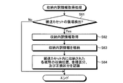
- FIG. 15 is a flowchart showing the processing operation of the control unit 63 of the teller machine 13 related to the storage breakdown information storage processing.
- Step S51A determines whether or not a removal preparation operation for the transport cassette 56 has been detected.
- the control unit 63 detects the removal preparation operation of the transport cassette 56 (Yes in Step S51A)
- the control unit 63 acquires the storage position, denomination and damage classification of the banknotes stored in the transport cassette 56 from the storage unit 62.
- the information creation unit 77 of the control unit 63 creates storage breakdown information by assigning a cash register number for identifying the change machine 12 to be replenished to the storage position, denomination category and damage category of each acquired banknote. (Step S52A).
- the storage control unit 73 of the control unit 63 stores the created storage breakdown information in the IC tag 16C of the transport cassette 56 (step S53A), removes the transport cassette 56 from the teller machine 13 (step S54A), and is shown in FIG. The processing operation is terminated.
- the control unit 63 ends this processing operation when the removal preparation operation of the transport cassette 56 is not detected (No at Step S51A).
- the replenishment destination register number and the storage position, denomination and damage classification of each banknote stored in the transport cassette 56 are displayed.
- Storage breakdown information to which an ATM number or the like is assigned is created. Further, the storage breakdown information is stored in the IC tag 16C of the transport cassette 56.
- the teller machine 13 that is the transfer source can notify the change machine 12 and the ATM machine 14 that are the transfer destination of the storage breakdown information of the transfer cassette 56 that is removed and transferred.
- FIG. 16 is a flowchart showing the processing operation of the control unit 33 of the change machine 12 related to the storage breakdown information acquisition processing.
- the control unit 33 shown in FIG. 16 determines whether or not the loading of the transport cassette 56 of the teller machine 13 with respect to the change machine 12 is detected (step S61A).
- the recognition unit 46 of the control unit 33 detects the loading of the transport cassette 56 (Yes at Step S61A)
- the recognition unit 46 acquires the storage breakdown information through the IC tag 16C of the transport cassette 56 (Step S62A).
- the storage control unit 43 of the control unit 33 stores the storage breakdown information in the storage unit 32 (step S63A).
- the recognizing unit 46 When the recognizing unit 46 stores the storage breakdown information in the storage unit 32, the recognizing unit 46 recognizes the storage position, denomination and damage classification of each banknote stored in the transport cassette 56 (step S64A), and performs the processing shown in FIG. End the operation. If the control unit 63 does not detect the loading of the transport cassette 56 of the teller machine 13 with respect to the change machine 12 (No at step S61A), the control operation ends.
- the change machine 12 can recognize the storage position, denomination and damage classification of each banknote stored in the transport cassette 56 without using the identification unit 23.
- Example 2 when the balance information of the change machine 12 of the transfer destination is acquired, the replenishment number of banknotes to be replenished to the change machine 12 is calculated based on the acquired balance information. Furthermore, in the second embodiment, banknotes to be replenished to the change machine 12 are stored in the transport cassette 56 based on the calculated replenishment number of banknotes. As a result, the teller machine 13 can automatically store the replenishment breakdown number of banknotes to be replenished to the change machine 12 in the transport cassette 56 for each denomination and damage category.
- the storage breakdown information of the transport cassette 56 storing the replenished banknotes is created on the cashier 13 side, and the storage breakdown information of the generated transport cassette 56 is notified to the change machine 12. Further, in the second embodiment, when the storage breakdown information is acquired on the change machine 12 side, the denomination classification and the damage classification of each supplementary banknote stored in the transport cassette 56 are recognized based on the storage breakdown information. As a result, since the change machine 12 can recognize the denomination classification and the damage classification of each banknote without identifying each replenishing banknote stored in the transport cassette 56, the processing burden required for the identification is greatly reduced. it can.
- the replenishment breakdown number for each change to the change machine 12 is calculated based on the current and ideal stock information of the change machine 12.
- the mixed banknotes were thrown out from the outlet 54 or stored in the transport cassette 26 based on the replenishment breakdown number.
- the replenishment breakdown number of banknotes is calculated based on the current and ideal balance information of the change machine 12, and the banknotes are thrown in based on this replenishment breakdown quantity. You may make it throw out from the exit 54 or accommodate in the conveyance cassette 26.
- the loss classification is based on ECB regulations.
- the bank counter service is a fit ticket that is suitable for use of the ATM machine 14 and a non-use ticket that is not suitable for use of the ATM machine 14. You may make it use the teller ticket which can be used for the use of payout.
- the ECB No. 1 which throws out correct bills in the bank account transaction of the change machine 12 by increasing the number of held correct tickets in the change machine 12 and the teller machine 13 in the store while diverting the lost tickets.
- the provisions of Article 6 were to be observed. For example, while diverting an old ticket at the time of switching from an old ticket banknote to a new ticket banknote, increasing the number of new ticket possessions in the change machine 12 and the teller machine 13 in the store, and gradually collecting the old ticket, The change machine 12 and the teller machine 13 may be set.
- the teller machine 13 stores the bills inserted into the insertion slot 51 in the reflux stacker 55 regardless of the old and new.
- the teller machine 13 can increase the number of new ticket possessions in the machine by using not only new banknotes but also old banknotes for banknote replenishment.
- the teller machine 13 throws out the new banknote stored in the reflux stacker 55 from the outlet 54 or stores it in the transport cassette 56. As a result, it is possible to throw out new bills when replenishing bills to the replenishment destination.
- the teller machine 13 throws out the old banknote stored in the reflux stacker 55 from the outlet 54 or stores it in the transport cassette 56.
- the old ticket banknotes are thrown out from the outlet 54 or stored in the transport cassette 56, whereby the number of new ticket possessions in the machine can be increased.
- the replenishment destination is loaded with the transport cassette 56 that stores the replenished banknotes, the denomination and old and new classifications of the replenished banknotes can be recognized without identifying the replenished banknotes.
- the number of home country banknotes held in the change machine 12 and the teller machine 13 in the store while diverting the foreign country banknote may be set so that the foreign currency banknotes are gradually collected. Further, the teller machine 13 stores the bills inserted into the insertion slot 51 in the reflux stacker 55 regardless of the country division. As a result, the teller machine 13 can increase the number of the domestic banknotes in the machine by diverting not only the home country banknotes but also the other country banknotes.
- the teller machine 13 throws out the home country banknote stored in the reflux stacker 55 from the outlet 54 or stores it in the transport cassette 56. As a result, the home country banknote can be thrown out when the banknote is replenished to the replenishment destination. Further, when the banknote replenishment instruction of the mixed banknote including at least other country banknotes is detected, the teller machine 13 throws out the other country banknotes stored in the reflux stacker 55 from the outlet 54 and stores them in the transport cassette 56.
- the foreign banknotes are thrown out from the outlet 54 or stored in the transport cassette 56, so that the number of own country banknotes in the apparatus can be increased.
- the replenishment destination is loaded with the transport cassette 56 containing the replenished banknotes, the denomination and country classification of the replenished banknotes can be recognized without identifying the replenished banknotes.
- the banknotes of customers visiting the store are collected and the banknotes are returned to the customer, but a prepaid card equivalent to the amount of the collected banknotes is issued. May be.
- the distribution ratio of the correct bills distributed in the store can be further increased.
- privilege points may be given to the customer's membership card in response to the insertion of the banknote bill by the customer.
- the distribution ratio of the correct bills circulated in the store can be increased by increasing the operation of the machine for collecting the damaged bills with respect to the customer.
- the recovery machine 15 of the above embodiment may reject the correct bill when detecting the insertion of the correct bill from the customer.
- the banknote banknotes are recovered based on the correct / incorrect classification, but the old banknotes may be recovered based on the new / old classification. In this case, it is possible to increase the distribution ratio of new ticket banknotes distributed in the store while collecting old ticket banknotes in the store.
- the collecting machine 15 may collect other country banknotes based on the country classification. In this case, it is possible to increase the distribution ratio of the home country banknote distributed in the store while collecting the other country banknote in the store. In addition, you may apply to a wide area etc., without limiting to a store.
- the transport cassette 16 (26, 56) is transferred between the change machine 12 and the cashier 13, that is, between the transfer source banknote processing machine and the transfer destination banknote processing machine.
- the storage breakdown information was acquired through the IC tag 16C.
- the transfer source banknote processor notifies the transfer destination banknote processor of the storage breakdown information via the network instead of the IC tag 16C. good.
- the transfer destination banknote processing machine acquires the storage breakdown information of the transport cassette 16 via the network, and stores each of the transport cassette 16 stored in the transport cassette 16 It is possible to recognize the bill storage position, denomination classification and damage classification.
- a receipt printed with the storage breakdown information a barcode, a QR code, or the like may be used.
- control unit 63 of the above-described embodiment is configured to identify and manage each change machine 12 by the register number of the POS register 11 to which the change machine 12 is connected.
- the change machine has a cassette ID that identifies the transport cassette 16. 12 and the POS register 11 corresponding to the change machine 12 may be identified and managed.
- the denomination classification and the damage classification are stored in the storage breakdown information of the transport cassette 16 in association with the storage position (storage position identification information) of each banknote.
- the denomination classification and the damage classification classification may be stored in association with the serial number for identifying the banknote.
- the identification part 23 and the identification part 53 shall identify the serial number of a conveyance banknote.
- the transport cassette 16 that can be attached to and detached from both the change machine 12 and the cashier 13 has been described as an example.
- the transport cassette 16 can also be attached to and detached from the ATM machine 14, the recovery machine 15, and the like. It is good as possible configuration.
- the ATM machine 14 and the collection machine 15 are also made to function as a transfer source banknote processing machine or a transfer destination banknote processing machine that notifies the storage breakdown information of the transport cassette 16 while transporting banknotes using the transport cassette 16. May be.
- the transport cassette 16 (26, 56) has one tape reel type storage unit built in, but as shown in FIG. 17, a plurality of, for example, two tape reel type storage units are provided. 16A and 16B may be incorporated. In this case, the transport cassette 16 may store banknotes of the designated denominations to be collected in the storage units 16A and 16B with a distinction between damages.
- the bills are stored in a rainbow state according to the deduction for each denomination according to the designated denomination to be collected.
- the reflux stacker 25 and the transport cassette 26 in the change machine 12 of the above embodiment, and the reflux stacker 55 and the transport cassette 56 in the teller machine 13 adopt a tape reel method in which banknotes of a specified denomination are wound around a tape and collected.
- the return stacker 25 in the change machine 12 of the above-described embodiment stores the correct bills and the damaged bills together, for example, when only the correct bills are to be thrown out, the stored bills are sequentially fed out to the correct bills. , And temporarily transfer the banknotes to another reflux stacker 25.
- the lost ticket temporarily transferred to the other reflux stacker 25 is returned to the original reflux stacker 25.
- the return stacker 25 in the change machine 12 and the return stacker 55 in the teller machine 13 of the above-described embodiment are configured to store mixed banknotes with a mixture of damages using a tape reel method, but each return stacker 25 (55). It is also possible to separate the bill into a ticket for a correct ticket and a ticket for a bad ticket.
- the bank account transaction using a bank account for example, a withdrawal service, a loan service, a cash out service, etc. has been described as an example.
- a bank account for example, a withdrawal service, a loan service, a cash out service, etc.
- the present invention can also be applied to a service in which change bills are thrown out by subtracting the product amount from the loan amount by a credit company.
- the change amount at the time of cash settlement, the withdrawal amount at the time of bank account transaction, the loan amount and the cash-out amount are explained by the amount that can be covered by the banknote denomination. Needless to say, when there is no fraction, the fraction is thrown out as coins from the coin processing unit 12B.
- the replenishment number is calculated not using the current amount information but using the predicted amount information predicted from the amount change in the past experience.
- each component of each device illustrated is functionally described, and is not necessarily physically configured as illustrated, and a specific aspect of each device is illustrated. Needless to say, it cannot be limited.
- each device various processing functions performed by each device are performed on a CPU (Central Processing Unit) (or a microcomputer such as an MPU (Micro Processing Unit) or MCU (Micro Controller Unit)), or on the same CPU (or MPU, MCU, etc.).
- a CPU Central Processing Unit
- MPU Micro Processing Unit
- MCU Micro Controller Unit
- all or any part of the program may be executed on a program that is analyzed and executed by a microcomputer) or on hardware based on wired logic.
- the storage breakdown information of the transport cassette is notified to the transport destination, and the transport destination does not identify the money in the transport cassette.
- the money type classification and the damage classification are recognized based on the storage breakdown information, it is useful for, for example, an in-store funds management system for transporting funds in the store.
Landscapes
- Physics & Mathematics (AREA)
- General Physics & Mathematics (AREA)
- Business, Economics & Management (AREA)
- Accounting & Taxation (AREA)
- Finance (AREA)
- Financial Or Insurance-Related Operations Such As Payment And Settlement (AREA)
- Cash Registers Or Receiving Machines (AREA)
Abstract
出納機(13)と、釣銭機(12)と、出納機及び釣銭機双方に対して着脱可能とし、釣銭機から出納機へ移送する紙幣を収納する搬送カセット(16)とを有する貨幣移送システムであって、紙幣の金種区分及び正損区分を識別する釣銭機側の識別部(23)と、識別部の識別結果に基づき、搬送カセットに収納された紙幣毎の金種区分及び正損区分を管理する収納内訳情報を作成する釣銭機側の情報作成部(45)と、収納内訳情報を取得すると、この収納内訳情報に基づき、当該搬送カセットに収納された各貨幣の金種区分及び正損区分を認識する出納機側の認識部(76)とを有し、出納機側の紙幣識別の処理負担を大幅に軽減する。
Description
本発明は、移送元貨幣処理装置及び移送先貨幣処理装置間、例えば、店舗内の釣銭機及び出納機間で貨幣を移送する貨幣移送システム、貨幣移送システムの貨幣移送方法及び貨幣処理装置用搬送カセットに関する。
従来、スーパーマーケットやコンビニエンスストア等の小売店やレストラン等のサービス店の精算所にあるPOS(Point Of Sales)レジスタ等のキャッシュレジスタに、硬貨入出金機及び紙幣入出金機等の釣銭機を接続したシステムが知られている(例えば、特許文献1参照)。
特許文献1の釣銭機では、商品現金取引機能による商品代金の投入や釣銭紙幣の投出のみならず、銀行口座取引機能の引出サービスによる引出金や貸付サービスによる貸付金を顧客に投出できる。尚、商品現金取引機能とは、商品購入時に商品代金を現金で支払う現金決済機能に相当する。更に、銀行口座取引機能には、預金口座の引出や貸付と同時に商品代金を支払う際、その引出金や貸付金を外部に投出することなく、引出金額や貸付金額から商品代金を差し引いた代金をキャッシュアウト金として顧客に投出するサービスがある。
銀行口座取引機能を備えた釣銭機では、例えば、5000円の商品購入と同時に預金口座から3万円の預金を引き出す際、この引出金額3万円から商品代金5000円を差し引いたキャッシュアウト金額25000円を顧客に投出する。
その結果、特許文献1では、銀行口座取引機能を利用し、商品購入時に預金口座の引出金額から商品代金を差し引いたキャッシュアウト金額を投出するようにしたので、顧客は、預金を引き出しながら、その引出金額の一部を商品代金に充当できる。
また、従来の釣銭機としては、入金紙幣の一部を釣銭紙幣として還流利用する機能を備えたものが知られている(例えば、特許文献2参照)。釣銭機は、入金紙幣を識別し、その入金紙幣が正券の場合、その入金紙幣をスタッカに収納する。また、釣銭機は、その入金紙幣が損傷度合の高い損券の場合、その入金紙幣をリジェクト収納部に収納する。
その結果、特許文献2では、入金紙幣の識別結果に基づき、入金紙幣が正券の場合、その入金紙幣を釣銭紙幣として還流利用できると共に、入金紙幣が損券の場合、その入金紙幣を回収できる。
また、流通店舗に配置された出納機は、紙幣の入金処理及び釣銭等の出金処理等の機能を備えている(例えば、特許文献3参照)。更に、出納機は、入金処理を通じて店舗内の売上金を回収する。そして、出納機で回収された店舗内の売上金は、回収業務を委託された現金配送会社によって現金処理センタに移送される。
また、金融機関で使用する出納機としては、紙幣の正損区分を識別し、この識別結果に基づき、正券紙幣及び損券紙幣に分別して収納する機能が知られている(例えば、特許文献4参照)。この出納機では、正券紙幣を出金紙幣として流用し、損券紙幣を回収して出金紙幣としての流用を禁止している。
また、流通店舗内の釣銭機及び出納機間での紙幣の搬送は手動で行われている。そこで、例えば、出納機から釣銭機へ貨幣を出金する際に通知される出金額と、その出金貨幣を釣銭機に入金した際に通知される入金額とを比較判定するシステムが知られている(例えば、特許文献5参照)。特許文献5のシステムでは、出金額と入金額とが同一額の場合に、釣銭機及び出納機間で正常な貨幣の入出金が行われたものと認識できる。
欧州のユーロ圏においては、金融機関の金融取引、例えば、預金口座の引出サービスや貸付サービス等の銀行口座取引では、従来、ECB第6条(Article 6 of the Council Regulation (EC) No.1138/2001 of 28 June 2001)が適用されている。このECB第6条では、金融機関の金融取引に際して、顧客への投出紙幣には正券紙幣を使用することが義務付けられている。また、近年、流通業界における釣銭機では、顧客に釣銭紙幣を投出する商品現金取引機能だけでなく、預金口座の引出サービスや貸付サービス等の銀行口座取引機能も利用できる。そこで、2011年からは金融機関の金融取引に限定することなく、流通市場での銀行口座取引においても、その投出紙幣は正券紙幣を使用することが義務付けられる可能性が高い。
しかしながら、上記従来の釣銭機では、銀行口座取引での紙幣投出に際しては正券又は損券の区別なしに紙幣を投出しているため、2011年以降は銀行口座取引で損券紙幣を投出した場合にはECB第6条の規定に違反することになる。
しかも、ECB第6条の規定を遵守するために、流通市場で使用する釣銭機では機内の正券保有枚数を増やす必要があるため、正券紙幣の需要増に伴って、流通市場から正券紙幣が不足して銀行口座取引のサービスが提供できなくなるといった事態も考えられる。
そこで、このような流通市場の店舗内に配置した釣銭機の資金を管理する出納機においても、正券紙幣の需要増による正券紙幣の不足に対処すべく、機内の正券保有枚数を増やす必要がある。
従って、今後、釣銭機及び出納機、すなわち、移送先及び移送元間での紙幣回収や紙幣補充に際しては、移送元から移送先へ正券及び損券が混在する混在紙幣を移送する機会が増える。しかしながら、移送先では、移送元から移送された混在紙幣の正損を認識するために、その混在紙幣の正損を再度識別する必要があるため、その処理負担は大きい。
本発明は上記点に鑑みてなされたものであり、その目的とするところは、移送元から移送先へ貨幣を移送した場合でも、貨幣識別の移送先側の処理負担を大幅に軽減できる貨幣移送システム、貨幣移送システムの貨幣移送方法及び貨幣処理装置用搬送カセットを提供することにある。
上記目的を達成するために本発明の貨幣移送システムは、移送先貨幣処理装置と、移送元貨幣処理装置と、前記移送先貨幣処理装置及び前記移送元貨幣処理装置双方に対して着脱可能とし、前記移送元貨幣処理装置から前記移送先貨幣処理装置へ移送する貨幣を収納する搬送カセットとを有する貨幣移送システムであって、前記貨幣の金種区分及び、正券及び損券を区分する正損区分を識別する前記移送元貨幣処理装置側の識別部と、前記識別部の識別結果に基づき、前記搬送カセットに収納された貨幣毎の金種区分及び正損区分を管理する収納内訳情報を作成する前記移送元貨幣処理装置側の情報作成部と、前記情報作成部によって作成された前記搬送カセットの前記収納内訳情報を前記移送先貨幣処理装置に通知する通知部と、前記通知部によって通知された前記収納内訳情報を取得すると、この収納内訳情報に基づき、当該搬送カセットに収納された各貨幣の金種区分及び正損区分を認識する前記移送先貨幣処理装置側の認識部とを有するようにした。
本発明の貨幣移送システムは、前記収納内訳情報が、前記搬送カセット内に収納する貨幣を識別するために、当該貨幣の収納位置を識別する収納位置識別情報を含む。
本発明の貨幣移送システムは、前記収納内訳情報が、前記搬送カセット内に収納する貨幣を識別するために、当該貨幣の記番号情報を含む。
本発明の貨幣移送システムは、前記搬送カセットが、特定金種の正券及び損券に区別して収納する、少なくとも2個の収納部を有するようにした。
本発明の貨幣移送システムは、前記通知部が、前記移送先貨幣処理装置及び前記移送元貨幣処理装置間を通信接続するネットワーク経由で、前記搬送カセットの前記収納内訳情報を前記移送先貨幣処理装置に通知するようにした。
本発明の貨幣移送システムは、前記通知部が、前記搬送カセットに備えた、前記収納内訳情報を記憶した記憶媒体経由で、当該搬送カセットの前記収納内訳情報を前記移送先貨幣処理装置に通知するようにした。
本発明の貨幣移送システムは、前記移送先貨幣処理装置が、店舗内の出納機に相当し、前記移送元貨幣処理装置が、店舗内の釣銭機に相当するようにした。
上記目的を達成するために本発明の貨幣移送システムの貨幣移送方法は、移送先貨幣処理装置と、移送元貨幣処理装置と、前記移送先貨幣処理装置及び前記移送元貨幣処理装置双方に対して着脱可能とし、前記移送元貨幣処理装置から前記移送先貨幣処理装置へ移送する貨幣を収納する搬送カセットとを有する貨幣移送システムの貨幣移送方法であって、前記貨幣の金種区分及び、正券及び損券を区分する正損区分を識別する前記移送元貨幣処理装置側の識別ステップと、前記識別ステップの識別結果に基づき、前記搬送カセットに収納された貨幣毎の金種区分及び正損区分を管理する収納内訳情報を作成する前記移送元貨幣処理装置側の情報作成ステップと、前記情報作成ステップによって作成された前記搬送カセットの前記収納内訳情報を前記移送先貨幣処理装置に通知する通知ステップと、前記通知ステップによって通知された前記収納内訳情報を取得すると、この収納内訳情報に基づき、当該搬送カセットに収納された各貨幣の金種区分及び正損区分を認識する前記移送先貨幣処理装置側の認識ステップとを含むようにした。
また、本発明の貨幣搬送システムは、移送先貨幣処理装置と、移送元貨幣処理装置と、前記移送先貨幣処理装置及び前記移送元貨幣処理装置双方に対して着脱可能とし、前記移送元貨幣処理装置から前記移送先貨幣処理装置へ移送する貨幣を収納する搬送カセットとを有する貨幣移送システムであって、前記貨幣の金種区分及び、新券及び旧券を区分する新旧区分を識別する前記移送元貨幣処理装置側の識別部と、前記識別部の識別結果に基づき、前記搬送カセットに収納された貨幣毎の金種区分及び新旧区分を管理する収納内訳情報を作成する前記移送元貨幣処理装置側の情報作成部と、前記情報作成部によって作成された前記搬送カセットの前記収納内訳情報を前記移送先貨幣処理装置に通知する通知部と、前記通知部によって通知された前記収納内訳情報を取得すると、この収納内訳情報に基づき、当該搬送カセットに収納された各貨幣の金種区分及び新旧区分を認識する前記移送先貨幣処理装置側の認識部とを有するようにした。
本発明の貨幣処理装置用搬送カセットは、移送先貨幣処理装置及び移送元貨幣処理装置双方に対して着脱可能にする装着インタフェースと、前記移送元貨幣処理装置から前記移送先貨幣処理装置へ移送する特定金種の貨幣を正券及び損券に区別して収納する、少なくとも2個の収納部とを有するようにした。
本発明の貨幣移送システムは、移送先貨幣処理装置と、移送元貨幣処理装置と、前記移送先貨幣処理装置及び前記移送元貨幣処理装置双方に対して着脱可能とし、前記移送元貨幣処理装置から前記移送先貨幣処理装置へ移送する貨幣を収納する搬送カセットとを有する貨幣移送システムであって、前記移送先貨幣処理装置で管理する金種区分及び正損区分毎の保有貨幣の在高情報を取得する前記移送元貨幣処理装置側の在高情報取得部と、前記移送先貨幣処理装置の在高情報に基づき、前記移送先貨幣処理装置に補充する前記貨幣の補充内訳数を算出する前記移送元貨幣処理装置側の内訳算出部と、前記内訳算出部にて算出した前記補充内訳数に基づき、前記移送先貨幣処理装置に補充する貨幣を前記搬送カセット内に収納する前記移送元貨幣処理装置側の制御部とを有するようにした。
本発明の貨幣移送システムは、前記内訳算出部が、前記移送先貨幣処理装置のキャッシュアウト機能の有無に基づき、前記移送先貨幣処理装置に補充する貨幣の補充内訳数を算出するようにした。
本発明の貨幣移送システムは、前記貨幣の金種区分及び、正券及び損券を区分する正損区分を識別する前記移送元貨幣処理装置側の識別部と、前記識別部の識別結果に基づき、前記搬送カセットに収納された貨幣毎の金種区分及び正損区分を管理する収納内訳情報を作成する前記移送元貨幣処理装置側の情報作成部と、前記情報作成部によって作成された前記搬送カセットの前記収納内訳情報を前記移送先貨幣処理装置に通知する通知部と、前記通知部によって通知された前記収納内訳情報を取得すると、この収納内訳情報に基づき、当該搬送カセットに収納された各貨幣の金種区分及び正損区分を認識する前記移送先貨幣処理装置側の認識部とを有するようにした。
本発明の貨幣移送システムは、前記移送先貨幣処理装置が、店舗内の釣銭機に相当し、前記移送元貨幣処理装置が、店舗内の出納機に相当するようにした。
本発明の貨幣移送システムの貨幣移送方法は、移送先貨幣処理装置と、移送元貨幣処理装置と、前記移送先貨幣処理装置及び前記移送元貨幣処理装置双方に対して着脱可能とし、前記移送元貨幣処理装置から前記移送先貨幣処理装置へ移送する貨幣を収納する搬送カセットとを有する貨幣移送システムの貨幣移送方法であって、前記移送先貨幣処理装置で管理する金種区分及び正損区分毎の保有貨幣の在高情報を取得する前記移送元貨幣処理装置側の在高情報取得ステップと、前記移送先貨幣処理装置の在高情報に基づき、前記移送先貨幣処理装置に補充する前記貨幣の補充内訳数を算出する前記移送元貨幣処理装置側の内訳算出ステップと、前記内訳算出ステップにて算出した前記補充内訳数に基づき、前記移送先貨幣処理装置に補充する貨幣を前記搬送カセット内に収納する前記移送元貨幣処理装置側の制御ステップとを含むようにした。
上記のように構成された本発明の貨幣移送システムでは、搬送カセットの収納内訳情報を移送元貨幣処理装置側で作成し、この作成した搬送カセットの収納内訳情報を移送先貨幣処理装置に通知する。更に、本発明の貨幣移送システムでは、移送先貨幣処理装置側で収納内訳情報を取得すると、収納内訳情報に基づき、当該搬送カセットに収納された各貨幣の金種区分及び正損区分を認識する。その結果、移送先貨幣処理装置では、搬送カセットに収納された各貨幣を識別しなくても、各貨幣の金種区分及び正損区分を認識できるため、その識別に要する処理負担を大幅に軽減できるという効果を奏する。
本発明の貨幣移送システムでは、貨幣を識別するのに収納位置識別情報を収納内訳情報に含めるようにしたので、移送先貨幣処理装置は、収納位置識別情報に基づき、搬送カセット内の貨幣を識別できるという効果を奏する。
本発明の貨幣移送システムでは、貨幣を識別するのに記番号情報を収納内訳情報に含めるようにしたので、移送先貨幣処理装置は、記番号情報に基づき、搬送カセット内の貨幣を識別できるという効果を奏する。
本発明の貨幣移送システムでは、搬送カセットが少なくとも2個の収納部を有するので、特定金種の正券及び損券を区別して収納できるという効果を奏する。
本発明の貨幣移送システムでは、搬送カセットの収納内訳情報をネットワーク経由で移送先貨幣処理装置に通知するようにしたので、移送先貨幣処理装置は、搬送カセットの収納内訳情報を取得できるという効果を奏する。
本発明の貨幣移送システムでは、搬送カセットの収納内訳情報を記憶媒体経由で移送先貨幣処理装置に通知するようにしたので、移送先貨幣処理装置は、搬送カセットの収納内訳情報を取得できるという効果を奏する。
本発明の貨幣移送システムでは、搬送カセットの収納内訳情報を釣銭機側で作成し、この作成した搬送カセットの収納内訳情報を出納機に通知する。更に、本発明の貨幣移送システムでは、出納機側で収納内訳情報を取得すると、収納内訳情報に基づき、当該搬送カセットに収納された各貨幣の金種区分及び正損区分を認識する。その結果、出納機では、搬送カセットに収納された各貨幣を識別しなくても、各貨幣の金種区分及び正損区分を認識できるため、その識別に要する処理負担を大幅に軽減できるという効果を奏する。
上記のように構成された本発明の貨幣移送システムの貨幣移送方法では、搬送カセットの収納内訳情報を移送元貨幣処理装置側で作成し、この作成した搬送カセットの収納内訳情報を移送先貨幣処理装置に通知する。更に、本発明の貨幣移送方法では、移送先貨幣処理装置側で収納内訳情報を取得すると、収納内訳情報に基づき、当該搬送カセットに収納された各貨幣の金種区分及び正損区分を認識する。その結果、移送先貨幣処理装置では、搬送カセットに収納された各貨幣を識別しなくても、各貨幣の金種区分及び正損区分を認識できるため、その識別に要する処理負担を大幅に軽減できるという効果を奏する。
本発明の貨幣移送システムでは、搬送カセットの収納内訳情報を移送元貨幣処理装置側で作成し、この作成した搬送カセットの収納内訳情報を移送先貨幣処理装置に通知する。更に、本発明の貨幣移送システムでは、移送先貨幣処理装置側で収納内訳情報を取得すると、収納内訳情報に基づき、当該搬送カセットに収納された各貨幣の金種区分及び新旧区分を認識する。その結果、移送先貨幣処理装置では、搬送カセットに収納された各貨幣を識別しなくても、各貨幣の金種区分及び新旧区分を認識できるため、その識別に要する処理負担を大幅に軽減できるという効果を奏する。
本発明の貨幣処理装置用搬送カセットでは、移送先貨幣処理装置及び移送元貨幣処理装置双方に対して着脱可能とし、前記移送元貨幣処理装置から前記移送先貨幣処理装置へ移送する特定金種の貨幣を正券及び損券に区別して収納できるという効果を奏する。
本発明の貨幣移送システムでは、移送先貨幣処理装置の在高情報を取得すると、この取得した在高情報に基づき、移送先貨幣処理装置に補充する貨幣の補充内訳数を算出する。更に、本発明の貨幣移送システムでは、算出した貨幣の補充内訳数に基づき、移送先貨幣処理装置に補充する貨幣を搬送カセット内に収納する。その結果、移送元貨幣処理装置は、移送先貨幣処理装置に補充すべき、金種区分及び正損区分毎の補充内訳数の貨幣を搬送カセットに自動的に収納できるという効果を奏する。
本発明の貨幣移送システムでは、移送先貨幣処理装置のキャッシュアウト機能の有無に基づき、移送先貨幣処理装置に補充する貨幣の補充内訳数を算出するようにしたので、移送元貨幣処理装置は、キャッシュアウト機能の有無を考慮することで正券紙幣の補充有無を認識できるという効果を奏する。
本発明の貨幣移送システムでは、補充貨幣を収納した搬送カセットの収納内訳情報を移送元貨幣処理装置側で作成し、この作成した搬送カセットの収納内訳情報を移送先貨幣処理装置に通知する。更に、本発明の貨幣移送システムでは、移送先貨幣処理装置側で収納内訳情報を取得すると、収納内訳情報に基づき、当該搬送カセットに収納された各補充貨幣の金種区分及び正損区分を認識する。その結果、移送先貨幣処理装置では、搬送カセットに収納された各補充貨幣を識別しなくても、各貨幣の金種区分及び正損区分を認識できるため、その識別に要する処理負担を大幅に軽減できるという効果を奏する。
本発明の貨幣移送システムでは、移送先である釣銭機の在高情報を取得すると、この取得した在高情報に基づき、釣銭機に補充する貨幣の補充内訳数を算出する。更に、本発明の貨幣移送システムでは、算出した貨幣の補充内訳数に基づき、釣銭機に補充する貨幣を搬送カセット内に収納する。その結果、移送元である出納機は、釣銭機に補充すべき、金種区分及び正損区分毎の補充内訳数の貨幣を搬送カセットに自動的に収納できるという効果を奏する。
本発明の貨幣移送システムの貨幣移送方法では、移送先貨幣処理装置の在高情報を取得すると、この取得した在高情報に基づき、移送先貨幣処理装置に補充する貨幣の補充内訳数を算出する。更に、本発明の貨幣移送システムでは、算出した貨幣の補充内訳数に基づき、移送先貨幣処理装置に補充する貨幣を搬送カセット内に収納する。その結果、移送元貨幣処理装置は、移送先貨幣処理装置に補充すべき、金種区分及び正損区分毎の補充内訳数の貨幣を搬送カセットに自動的に収納できるという効果を奏する。
以下、図面に基づき本発明の貨幣移送システム、貨幣移送システムの貨幣移送方法及び貨幣処理装置用搬送カセットに関わる実施例について詳細に説明する。
まず、最初に本実施例の概要を説明するとすれば、その概要は、移送元貨幣処理装置及び移送先貨幣処理装置双方に着脱可能な搬送カセットを使用して移送元貨幣処理装置から移送先貨幣処理装置へ紙幣を移送する際に、搬送カセットに収納された貨幣の金種区分及び正損区分を含む収納内訳情報を移送先貨幣処理装置に通知する。その結果、移送先貨幣処理装置は、搬送カセットに収納された各貨幣を識別しなくても、各貨幣の金種区分及び正損区分を認識できるため、その識別に要する処理負担を大幅に軽減できるというものである。
図1は、実施例1の店舗内資金管理システムの構成を示すブロック図である。図1に示す店舗内資金管理システム1は、POSレジスタ11、釣銭機12、セルフレジユニット11A、出納機13、ATM機14、回収機15及び搬送カセット16を有する。POSレジスタ11は、精算所に配置され、POS機能を利用して顧客の購入商品を管理すると共に、その購入商品の商品代金を精算する対面対応の有人レジスタに相当する。釣銭機12は、POSレジスタ11に隣接配置し、POSレジスタ11等で精算した商品金額の現金を投入口から投入すると共に、商品金額から現金投入金額を差し引いた釣銭貨幣を投出口から投出する。尚、釣銭機12には、釣銭貨幣の釣銭紙幣を投出する紙幣処理部12Aや、釣銭貨幣の釣銭硬貨を投出する硬貨処理部12Bを有する。セルフレジユニット11Aは、精算所に配置され、顧客自らが精算を行えるように、前述のPOSレジスタ11、釣銭機12及び不正防止用の計量装置等を一体的にシステム構成されたもので、顧客の購入商品を管理すると共に、その購入商品の商品代金を精算する無人精算ユニットに相当する。出納機13は、店舗内の全釣銭機12を通じて店舗内の現金資金を金種別及び正損別に管理する。ATM機14は、店舗内で銀行サービスを提供する現金自動払出機に相当する。回収機15は、後述するが、例えば、店舗の入口に配置して来店した顧客の損券紙幣を回収し、その損券紙幣同額の正券紙幣を顧客に返却する。また、現金配送会社17は、店舗からの配送依頼に応じて、出納機13で管理する店舗内の現金資金の内、例えば、売上金を回収し、その回収した売上金を金融機関に配送する。更に、現金配送会社17は、店舗からの配送依頼に応じて、金種別や正損別に店舗運用の準備金を店舗に配送する。
図2は、釣銭機12の紙幣処理部12Aの内部構成を示す説明図であり、以下、この紙幣処理部12Aを釣銭機12として説明する。図3は、釣銭機12の内部構成を示すブロック図である。図2に示す釣銭機12は、投入口21、搬送部22、識別部23、投出口24、還流スタッカ25、搬送カセット26、リーダライタ27及び制御部33を有する。投入口21は、釣銭機12内に紙幣を投入する入口に相当する。搬送部22は、搬送ベルト等で構成され、投入口21、還流スタッカ25、搬送カセット26及び投出口24間の搬送路上で紙幣を搬送する。尚、搬送路上の分岐箇所には、図示せぬ分岐部を配置し、図示せぬ検知センサを通じて紙幣の先端の進入を検知すると、図示せぬソレノイドが駆動することで搬送紙幣を振り分ける。
識別部23は、搬送路上に配置され、投入口21から投入された紙幣の種別を識別する。尚、紙幣種別には、例えば、ユーロ紙幣の場合、5ユーロ、10ユーロ、20ユーロ、50ユーロ、100ユーロ、200ユーロ及び500ユーロの7種類の金種区分の他に、真券・偽券を識別する真偽区分、正券・損券を識別する正損区分がある。尚、正損区分は、ECBの規定による。更に、紙幣種別には、表裏を識別する表裏区分や、金種毎の新券・旧券を識別する刷版区分等がある。
還流スタッカ25は、指定金種毎に、投入口21から投入された紙幣を収納すると共に、その収納された紙幣を投出口24に投出する際に繰り出す。尚、還流スタッカ25は、テープリール方式を採用して、1枚単位で紙幣をテープに巻付けながらリール25Aに収納する。図2に示す釣銭機12の例では、合計5個の還流スタッカ25を備えているものとする。
搬送カセット26は、回収対象の指定紙幣を回収する指定紙幣回収部26Aと、カセット表面に貼付され、後述する収納内訳情報を格納したICタグ16Cとを有する。尚、指定紙幣回収部26Aは、テープリール方式を採用している。投出口24は、前述のように還流スタッカ25から投出された紙幣の投出を行うと共に、投入口24から投入された紙幣の識別結果に基づき、リジェクト対象の紙幣を釣銭機12の外部に投出する。リーダライタ27は、搬送カセット26に貼付されたICタグ16Cに格納する収納内訳情報等をリードライトする。
更に、図3に示す釣銭機12は、通信インタフェース31、記憶部32及び制御部33を有する。通信インタフェース31は、POSレジスタ11と接続すると共に、図示せぬネットワーク経由で出納機13と通信接続する。記憶部32は、還流スタッカ25や搬送カセット26毎に、当該還流スタッカ25及び搬送カセット26内に収納された各紙幣の収納位置、金種区分及び正損区分を記憶管理する。更に、記憶部32は、釣銭機12内の金種別及び正損別の現在の在高情報を記憶管理する。
制御部33は、投出指示検出部41、駆動制御部42、記憶制御部43、釣銭算出部44及び情報作成部45を有する。投出指示検出部41は、商品現金取引に関わる取引金額対応の紙幣投出指示又は銀行口座取引に関わる取引金額対応の紙幣投出指示を検出する。尚、商品現金取引又は銀行口座取引は、図示せぬ操作部の所定操作に応じて起動する。
釣銭算出部44は、商品現金取引、すなわち現金決済の場合、商品購入に際して現金を投入口21に投入し、現金投入金額から商品金額を差し引いた釣銭金額を算出する。ここで、図4により、釣銭機12のサービス内容について説明する。図4(A)に示すように、釣銭機12は、現金投入金額が100ユーロ、商品金額が20ユーロとして現金決済する場合、80ユーロの釣銭紙幣を投出口24から投出することになるが、この場合は、正券であっても損券であっても良い。また、釣銭算出部44は、銀行口座取引のキャッシュアウトサービス時に、商品購入に際して引出金額又は貸付金額から商品金額を差し引いたキャッシュアウト金額を算出する。図4(B)に示すように、釣銭機12は、引出金額が100ユーロ、商品金額が20ユーロとしてデビット決済する場合、引出金額から商品金額を差し引いた80ユーロのキャッシュアウト金額を正券紙幣として投出口24から投出することになる。また、図4(C)に示すように、釣銭機12は、例えば、引出サービスとして引出金額が100ユーロの場合、引出金額を100ユーロとして正券紙幣で投出口24から投出することになる。
駆動制御部42は、銀行口座取引に関わる取引金額対応の紙幣の投出指示を検出すると、還流スタッカ25に収納された銀行口座取引に関わる取引金額対応の正券紙幣を投出口24から投出すべく、還流スタッカ25及び搬送部22を駆動制御する。尚、銀行口座取引では、引出サービス、貸付サービス及びキャッシュアウトサービスでも正券紙幣を投出することになるため、ECB第6条の規定を遵守できる。
駆動制御部42は、商品現金取引に関わる取引金額対応の釣銭紙幣の投出指示を検出すると、還流スタッカ25に収納された商品現金取引に関わる取引金額対応の損券紙幣を投出口24から投出すべく、還流スタッカ25及び搬送部22を駆動制御する。
記憶制御部43は、識別部23の識別結果に基づき、投入口21から投入された紙幣を還流スタッカ25又は搬送カセット26に収納する場合、その収納位置毎に当該紙幣の金種区分及び正損区分を記憶部32に記憶するものである。更に、記憶制御部43は、釣銭機12内に収納された全紙幣の金種区分及び正損区分を含む金種別及び正損別の現在の在高情報を記憶部32内に記憶する。更に、情報作成部45は、指定金種の紙幣を搬送カセット26に収納した場合、当該搬送カセット26に収納された各紙幣の収納位置、金種区分、正損区分及びレジ番号を含む収納内訳情報を作成する。更に、記憶制御部43は、収納内訳情報を搬送カセット26に貼付したICタグに格納する。
尚、還流スタッカ25は、テープリール方式を採用して、正損区分に関係なく、指定金種の紙幣を収納している。従って、指定金種の正券紙幣又は損券紙幣のどちらか一方を指定して搬送部22に繰り出すには時間を要する。例えば、還流スタッカ25内に、図示せぬ収納口の直近位置から損券→正券→正券→正券→正券→損券→…の順に20ユーロ紙幣が収納されたとする。この際、還流スタッカ25から20ユーロ紙幣の2枚の損券を繰り出す場合、駆動制御部42は、1枚目の紙幣として損券を繰り出す。更に、駆動制御部42は、2枚目~5枚目の紙幣として正券を順次繰り出し、これら正券を他の還流スタッカ25に順次移送する。更に、駆動制御部42は、6枚目の紙幣として損券を繰り出すことで、合計2枚の20ユーロ紙幣の損券を繰り出したことになる。従って、2枚の20ユーロ紙幣の損券を繰り出すのに合計6枚の紙幣を繰り出す必要がある。しかも、他の還流スタッカ25に移送した4枚の正券は元の還流スタッカ25に戻す必要があるため、時間を要する。
そこで、駆動制御部42は、還流スタッカ25に収納された現金決済時の釣銭金額対応の損券紙幣を優先的に投出口24から投出する場合でも、還流スタッカ25から損券紙幣を繰り出すのに時間を要する場合、損券紙幣の代わりに、正券紙幣を投出口24から投出すべく、還流スタッカ25及び搬送部22を駆動制御する。その結果、現金決済時の釣銭金額対応の紙幣を投出する処理負担を軽減しながら、その投出時間を大幅に短縮化できる。
更に、駆動制御部42は、還流スタッカ25から損券紙幣を搬送部22に繰り出すのに時間を要する場合、損券紙幣の代わりに、還流スタッカ25に収納された損券紙幣同額の低額金種構成の損券紙幣を投出口24から投出すべく、還流スタッカ25及び搬送部22を駆動制御する。尚、同額の低額金種構成の紙幣とは、例えば、40ユーロの紙幣を投出する場合、通常金種構成なら20ユーロ紙幣を2枚で賄うことになるが、低額金種構成なら10ユーロ紙幣4枚や、20ユーロ紙幣1枚、10ユーロ紙幣2枚の金種構成等で賄うことになる。また、駆動制御部42は、還流スタッカ25から正券紙幣を搬送部22に繰り出すのに時間を要する場合、正券紙幣の代わりに、還流スタッカ25に収納された正券紙幣同額の低額金種構成の正券紙幣を投出口24から投出すべく、還流スタッカ25及び搬送部22を駆動制御する。
また、駆動制御部42は、還流スタッカ25に収納された現金決済時の釣銭金額対応の損券紙幣を優先的に投出口24から投出するモードが設定された場合でも、現金決済に際して投入口21から投入された紙幣が全て正券であった場合には、還流スタッカ25に収納された当該商品現金取引に関わる取引金額対応の正券紙幣を投出口24から投出すべく、還流スタッカ25及び搬送部22を駆動制御する。
また、駆動制御部42は、指定金種の損券紙幣を回収対象に指定した場合、還流スタッカ25に収納された紙幣から損券紙幣を優先的に搬送カセット26に搬送すべく、還流スタッカ25及び搬送部22を駆動制御する。尚、駆動制御部42は、指定金種の正券紙幣を回収対象にした場合、同様に還流スタッカ25に収納された紙幣から正券紙幣を優先的に搬送カセット26に搬送する。尚、指定金種は複数金種であっても良いことは言うまでもない。
また、駆動制御部42は、回収対象として指定金種別枚数の損券紙幣を指定した場合、還流スタッカ25に収納された指定金種の指定枚数分の損券紙幣を優先的に搬送カセット26に搬送すべく、還流スタッカ25及び搬送部22を駆動制御する。尚、駆動制御部42は、回収対象として指定金種別枚数の正券紙幣を指定した場合、還流スタッカ25に収納された指定金種の指定枚数分の正券紙幣を優先的に搬送カセット26に搬送する。
また、駆動制御部42は、回収対象として指定合計金額相当の損券紙幣を指定した場合、還流スタッカ25に収納された指定合計金額分の損券紙幣を優先的に搬送カセット26に搬送すべく、還流スタッカ25及び搬送部22を駆動制御する。尚、駆動制御部42は、回収対象として指定合計金額相当の正券紙幣を指定した場合、還流スタッカ25に収納された指定合計金額分の正券紙幣を優先的に搬送カセット26に搬送する。
また、駆動制御部42は、回収対象として指定合計金額を超えた超過分の損券紙幣を指定した場合、還流スタッカ25に収納された指定合計金額を超えた超過分の損券紙幣を優先的に搬送カセット26に搬送すべく、還流スタッカ25及び搬送部22を駆動制御する。尚、駆動制御部42は、回収対象として指定合計金額を超えた超過分の正券紙幣を指定した場合、還流スタッカ25に収納された指定合計金額を超えた超過分の正券紙幣を優先的に搬送カセット26に搬送する。
また、駆動制御部42は、回収対象として指定金種別枚数を超えた超過分の損券紙幣を指定した場合、還流スタッカ25に収納された指定金種の指定枚数を超えた超過分の損券紙幣を優先的に搬送カセット26に搬送すべく、還流スタッカ25及び搬送部22を駆動制御する。尚、駆動制御部42は、回収対象として指定金種別枚数を超えた超過分の正券紙幣を指定した場合、還流スタッカ25に収納された指定金種の指定枚数を超えた超過分の正券紙幣を優先的に搬送カセット26に搬送する。
また、駆動制御部42は、搬送カセット26に収納された紙幣を投出口24及び還流スタッカ25に搬送すべく、搬送カセット26及び搬送部22を駆動制御する。また、制御部33は、搬送カセット26に搬送すべき、回収対象の指定を、釣銭機12又は出納機13の図示せぬ操作部の指定操作で実行するものとする。また、釣銭機12は、投入口21への紙幣投入時に、当該投入紙幣が正券紙幣の場合、例えば、顧客会員カードに、正券紙幣の枚数に応じて特典ポイントを付与する機能を備えている。
図5は、出納機13の内部構成を示す説明図、図6は、出納機13の内部構成を示すブロック図である。図5に示す出納機13は、投入口51、搬送部52、識別部53、投出口54、還流スタッカ55、搬送カセット56(16)、リーダライタ57、操作・表示部58及び制御部63を有する。投入口51は、出納機13内に紙幣を投入する入口に相当する。搬送部52は、搬送ベルト等で構成され、投入口51、還流スタッカ55及び搬送カセット56間の搬送路上で紙幣を搬送する。尚、搬送路上の分岐箇所には、図示せぬ分岐部を配置し、図示せぬ検知センサを通じて紙幣の先端の進入を検知すると、図示せぬソレノイドが駆動することで搬送紙幣を振り分ける。
還流スタッカ55は、指定金種毎に9個備えられており、通常は指定金種毎に割り当てられているが、流通量の多い金種に2個の還流スタッカ55を割り当てたり、キャッシュアウトの可能性の高い金種に正券専用の還流スタッカ55を設定する等、任意に設定可能となっている。還流スタッカ55は、投入口51から投入された指定金種の投入紙幣を収納すると共に、その収納された紙幣を投出口54に投出する際に繰り出す。尚、還流スタッカ55は、テープリール方式を採用している。搬送カセット56は、釣銭機12の搬送カセット26と同一タイプの装填インタフェースを備え、出納機13は勿論のこと、釣銭機12に対しても装填及び取外し可能である。更に、搬送カセット56は、回収対象の指定紙幣を回収する指定紙幣回収部56Aと、カセット表面に貼付され、後述する収納内訳情報を格納したICタグ16Cとを有する。尚、釣銭機12の搬送カセット26は、搬送カセット56と同一タイプの装填インタフェースを備え、出納機13に対しても装填及び取外し可能である。リーダライタ57は、搬送カセット56(16)に貼付されたICタグ16Cに格納する収納内訳情報等をリードライトする。操作・表示部58は、タッチパネル式の操作・表示部に相当し、各種情報の入力及び表示を行う。
図6に示す出納機13は、搬送部52及び識別部53の他に、通信インタフェース61、記憶部62及び制御部63を有する。通信インタフェース61は、図示せぬネットワーク経由で各釣銭機12と通信接続する。
記憶部62は、還流スタッカ55や搬送カセット56毎に、当該還流スタッカ55及び搬送カセット56内に収納された各紙幣の収納位置、金種区分及び正損区分を記憶管理する。更に、記憶部62は、各釣銭機12の金種別及び正損別の現在の在高情報を記憶管理する。制御部63は、釣銭機12が接続するPOSレジスタ11のレジ番号で、各釣銭機12を識別管理する。
制御部63は、補充先指示検出部71、駆動制御部72、記憶制御部73、補充枚数算出部74、在高情報取得部75及び認識部76を有する。補充先指示検出部71は、出納機13が補充する紙幣の補充先、例えば、釣銭機12やATM機14等の補充先を指定する。
在高情報取得部75は、通信インタフェース61を通じてネットワーク経由で各釣銭機12やATM機14の金種区分及び正損区分の現在の在高情報を収集する。更に、記憶制御部73は、これら収集した各釣銭機12及びATM機14の現在の在高情報を記憶部62に記憶する。更に、認識部76は、出納機13内に釣銭機12の搬送カセット26が装填されると、搬送カセット26のICタグ16Cを通じて収納内訳情報を収集する。更に、認識部76は、収集した収納内訳情報に基づき、識別部53を使用しなくても、搬送カセット26に収納された各紙幣の収納位置、金種区分及び正損区分を認識する。
補充枚数算出部74は、補充先指示検出部71にて補充先を指定した補充指示を検出すると、補充先の現在の在高情報と、補充先の理想の在高情報とに基づき、当該補充先に補充すべき、金種及び正損別の紙幣枚数を補充内訳枚数として算出する。尚、制御部63は、補充先毎に理想の在高情報等をも記憶部62に記憶管理しているものとする。補充先の理想の在高情報とは、補充先として保有すべき、金種及び正損別の紙幣枚数に相当する。
駆動制御部72は、銀行口座取引機能を備えた釣銭機12を補充先として指定した補充指示を検出すると、補充枚数算出部74の算出結果に基づき、還流スタッカ55に収納された補充内訳枚数の正券紙幣及び損券紙幣を投出口54から投出すべく、還流スタッカ55及び搬送部52を駆動制御する。尚、駆動制御部72は、補充内訳枚数の正券紙幣及び損券紙幣を投出口54に投出せず、補充内訳枚数の正券紙幣及び損券紙幣を回収対象として搬送カセット56に搬送すべく、還流スタッカ55及び搬送部52を駆動制御するようにしても良い。
駆動制御部72は、銀行口座取引機能がない釣銭機12を補充先として指定した補充指示を検出すると、補充枚数算出部74の算出結果に基づき、還流スタッカ55に収納された補充内訳枚数の損券紙幣を投出口54から投出すべく、還流スタッカ55及び搬送部52を駆動制御する。尚、補充内訳枚数の紙幣を損券紙幣のみとしたが、正券紙幣のみ、若しくは正券紙幣を含む混在紙幣としても良い。また、駆動制御部72は、補充内訳枚数の損券紙幣を回収対象として搬送カセット56に搬送すべく、還流スタッカ55及び搬送部52を駆動制御するようにしても良い。
駆動制御部72は、ATM機14を指定先として指定した補充指示を検出すると、補充枚数算出部74の算出結果に基づき、還流スタッカ55に収納された補充内訳枚数の正券紙幣を投出口54から投出すべく、還流スタッカ55及び搬送部52を駆動制御する。尚、駆動制御部72は、補充内訳枚数の正券紙幣を回収対象として搬送カセット56に搬送すべく、還流スタッカ55及び搬送部52を駆動制御するようにしても良い。
更に、駆動制御部72は、還流スタッカ55から損券紙幣を搬送部52に繰り出すのに時間を要する場合、損券紙幣の代わりに、還流スタッカ55に収納された損券紙幣同額の低額金種構成の損券紙幣を投出口54から投出すべく、還流スタッカ55及び搬送部52を駆動制御する。尚、同額の低額金種構成の紙幣とは、例えば、40ユーロの紙幣を投出する場合、通常金種構成なら20ユーロ紙幣を2枚で賄うことになるが、低額金種構成なら10ユーロ紙幣4枚や、20ユーロ紙幣1枚、10ユーロ紙幣2枚の金種構成等で賄うことになる。また、駆動制御部72は、還流スタッカ55から正券紙幣を搬送部52に繰り出すのに時間を要する場合、正券紙幣の代わりに、還流スタッカ55に収納された正券紙幣同額の低額金種構成の正券紙幣を投出口54から投出すべく、還流スタッカ55及び搬送部52を駆動制御する。
また、駆動制御部72は、指定金種の損券紙幣を回収対象に指定した場合、還流スタッカ55に収納された損券紙幣を優先的に搬送カセット56に搬送すべく、還流スタッカ55及び搬送部52を駆動制御する。尚、駆動制御部72は、指定金種の正券紙幣を回収対象にした場合、同様に還流スタッカ55に収納された正券紙幣を優先的に搬送カセット56に搬送する。尚、指定金種は複数金種でも良いことは言うまでもない。
また、駆動制御部72が回収対象として指定金種別枚数の損券紙幣を指定した場合、還流スタッカ55に収納された指定金種の指定枚数分の損券紙幣を優先的に搬送カセット56に搬送すべく、還流スタッカ55及び搬送部52を駆動制御する。尚、駆動制御部72は、回収対象として指定金種別枚数の正券紙幣を指定した場合、還流スタッカ55に収納された指定金種の指定枚数分の正券紙幣を優先的に搬送カセット56に搬送する。
また、駆動制御部72は、回収対象として指定合計金額相当の損券紙幣を指定した場合、還流スタッカ55に収納された指定合計金額分の損券紙幣を優先的に搬送カセット56に搬送すべく、還流スタッカ55及び搬送部52を駆動制御する。尚、駆動制御部72は、回収対象として指定合計金額相当の正券紙幣を指定した場合、還流スタッカ55に収納された指定合計金額分の正券紙幣を優先的に搬送カセット56に搬送する。
また、駆動制御部72は、回収対象として指定合計金額を超えた超過分の損券紙幣を指定した場合、還流スタッカ55に収納された指定合計金額を超えた超過分の損券紙幣を優先的に搬送カセット56に搬送すべく、還流スタッカ55及び搬送部52を駆動制御する。尚、駆動制御部72は、回収対象として指定合計金額を超えた超過分の正券紙幣を指定した場合、還流スタッカ55に収納された指定合計金額を超えた超過分の正券紙幣を優先的に搬送カセット56に搬送する。
また、駆動制御部72は、回収対象として指定金種別枚数を超えた超過分の損券紙幣を指定した場合、還流スタッカ55に収納された指定金種別枚数を超えた超過分の損券紙幣を優先的に搬送カセット56に搬送すべく、還流スタッカ55及び搬送部52を駆動制御する。尚、駆動制御部72は、回収対象として指定金種別枚数を超えた超過分の正券紙幣を指定した場合、還流スタッカ55に収納された指定金種別枚数を超えた超過分の正券紙幣を優先的に搬送カセット56に搬送する。
また、駆動制御部72は、搬送カセット56に収納された紙幣を投出口54及び還流スタッカ55に搬送すべく、搬送カセット56及び搬送部52を駆動制御する。また、制御部63は、搬送カセット56に搬送すべき、回収対象の指定紙幣を、釣銭機12又は出納機13の図示せぬ操作部の指定操作で実行するものとする。
図7は、釣銭機12及び出納機13間の搬送カセット16(26、56)の移送関係を示す説明図である。釣銭機12の搬送カセット26は、出納機13に対しても装填取外し可能である。これに対して、出納機13の搬送カセット56は、釣銭機12に対しても装填取外し可能である。釣銭機12の情報作成部45は、指定金種の紙幣を搬送カセット26に収納した場合、当該搬送カセット26に収納された各紙幣の収納位置、金種区分、正損区分及びレジ番号を含む収納内訳情報を作成する。釣銭機12の記憶制御部43は、収納内訳情報を作成すると、この収納内訳情報を搬送カセット26に貼付したICタグ16Cに格納する。更に、店員は、釣銭機12から搬送カセット26を取り外し、この搬送カセット26を出納室に搬送する。そして、店員は、その搬送カセット26を出納機13内に装填する。そして、出納機13の認識部76は、搬送カセット26が装填されると、当該搬送カセット26のICタグ16Cを通じて収納内訳情報を取得する。更に、認識部76は、収納内訳情報に基づき、識別部53を通じて搬送カセット26に収納された各紙幣を識別しなくても、各紙幣の収納位置、金種区分及び正損区分を認識する。更に、記憶制御部73は、その収納内訳情報を記憶部62に記憶管理する。
また、店舗内の釣銭機12及び出納機13では、店舗内での銀行口座取引を円滑に運用するために正券保有枚数を増やす必要がある。そこで、店舗内に流通する正券の流通比率を高める必要があるため、店舗入口等に回収機15を配置した。回収機15は、投入口から顧客の損券紙幣が投入されると、投入金額対応の正券紙幣を投出口から顧客に投出する。その結果、店舗内での顧客による損券紙幣の使用を抑制することで、店舗内に流通する正券の流通比率を高めることができる。
次に、実施例1の店舗内資金管理システム1の動作について説明する。図8は、釣銭処理に関わる釣銭機12の制御部33の処理動作を示すフローチャートである。図8において釣銭機12の制御部33は、購入商品の商品金額が確定すると(ステップS11)、支払方法がデビット決済であるか否かを判定する(ステップS12)。尚、デビット決済は、銀行口座取引のキャッシュアウトサービスに相当する。制御部33の釣銭算出部44は、支払方法がデビット決済の場合(ステップS12肯定)、デビット決済の引出金額又は貸付金額から商品金額を差し引いてキャッシュアウト金額を確定し(ステップS13)、キャッシュアウト金額対応の紙幣があるか否かを判定する(ステップS13A)。
制御部33は、キャッシュアウト金額対応の紙幣がある場合(ステップS13A肯定)、キャッシュアウト金額対応の正券紙幣が還流スタッカ25内にあるか否かを判定する(ステップS14)。制御部33は、キャッシュアウト金額対応の正券紙幣が還流スタッカ25内にある場合に(ステップS14肯定)、還流スタッカ25内のキャッシュアウト金額対応の正券紙幣を投出口24から投出し(ステップS15)、図8に示す処理動作を終了する。
また、制御部33は、キャッシュアウト金額対応の紙幣がない場合(ステップS13A否定)、図8に示す処理動作を終了する。また、制御部33は、キャッシュアウト金額対応の正券紙幣が還流スタッカ25内にない場合に(ステップS14否定)、還流スタッカ25内に収納されたキャッシュアウト金額対応の低額金種構成の正券紙幣を投出口24から投出し(ステップS16)、図8に示す処理動作を終了する。
また、制御部33は、支払方法がデビット決済でない場合(ステップS12否定)、現金決済と判断し(ステップS17)、投入口21からの現金投入を検出する(ステップS18)。制御部33の釣銭算出部44は、現金投入金額から商品金額を差し引いて不足金があるか否かを判定する(ステップS19)。
制御部33は、現金投入金額から商品金額を差し引いて不足金がある場合に(ステップS19肯定)、不足金を報知し(ステップS20)、投入口21への現金投入を待機すべく、ステップS18に移行する。尚、不足金の報知方法としては、表示や音声等で報知するようにしても良い。
また、制御部33は、現金投入金額から商品金額を差し引いて不足金がない場合に(ステップS19否定)、釣銭金額が確定する(ステップS21)。制御部33は、釣銭金額が確定すると、釣銭金額対応の紙幣があるか否かを判定する(ステップS22)。制御部33は、釣銭金額対応の紙幣がある場合(ステップS22肯定)、投入口21に投入された全投入紙幣が正券であるか否かを判定する(ステップS23)。
制御部33は、全投入紙幣が正券である場合(ステップS23肯定)、還流スタッカ25内に釣銭金額対応の正券紙幣があるか否かを判定する(ステップS24)。制御部33は、釣銭金額対応の正券紙幣がある場合(ステップS24肯定)、還流スタッカ25に収納された釣銭金額対応の正券紙幣を投出口24から投出し(ステップS25)、図8に示す処理動作を終了する。
また、制御部33は、釣銭金額対応の紙幣がない場合(ステップS22否定)、図8に示す処理動作を終了する。制御部33は、全投入紙幣が正券でない場合(ステップS23否定)、還流スタッカ25内に釣銭金額対応の損券紙幣があるか否かを判定する(ステップS26)。制御部33は、釣銭金額対応の損券紙幣がある場合(ステップS26肯定)、還流スタッカ25に収納された釣銭金額対応の損券紙幣を投出口24から投出し(ステップS27)、図8に示す処理動作を終了する。
また、制御部33は、釣銭金額対応の損券紙幣がない場合(ステップS26否定)、還流スタッカ25内に釣銭金額対応の低額金種構成の損券紙幣があるか否かを判定する(ステップS28)。制御部33は、低額金種構成の損券紙幣がある場合に(ステップS28肯定)、還流スタッカ25に収納された低額金種構成の損券紙幣を投出口24から投出し(ステップS29)、図8に示す処理動作を終了する。
また、制御部33は、釣銭金額対応の低額金種構成の損券紙幣がない場合(ステップS28否定)、損券紙幣に限定することなく、還流スタッカ25に収納された釣銭金額対応の正券紙幣を投出口24から投出し(ステップS30)、図8に示す処理動作を終了する。
また、制御部33は、還流スタッカ25内に釣銭金額対応の正券紙幣がない場合(ステップS24否定)、正券紙幣に限定することなく、還流スタッカ25に収納された釣銭金額対応の損券紙幣を投出口24から投出し(ステップS31)、図8に示す処理動作を終了する。
図8に示す釣銭処理では、商品購入のデビット決済時に、引出金額又は貸付金額から商品金額を差し引いたキャッシュアウト金額対応の紙幣がある場合、そのキャッシュアウト金額対応の紙幣を正券紙幣で投出口24から投出する。その結果、釣銭機12は、ECB第6条の規定を遵守できる。
釣銭処理では、商品購入の現金決済時に、投入金額から商品金額を差し引いた釣銭金額の紙幣がある場合、その釣銭金額の紙幣を損券紙幣で投出口24から投出する。その結果、釣銭機12は、正券紙幣の流出を抑制して機内の正券保有枚数を増やせる。
釣銭処理では、現金決済時に、投入金額から商品金額を差し引いた釣銭金額の紙幣があり、その釣銭金額対応の損券紙幣がない場合、釣銭金額対応の低額金種構成の損券紙幣を投出口24から投出する。その結果、釣銭機12は、正券紙幣の流出を抑制しながら、顧客に釣銭紙幣を返却できる。
釣銭処理では、現金決済時に、投入金額から商品金額を差し引いた釣銭金額の紙幣があり、その釣銭金額対応の損券紙幣がなく、釣銭金額対応の低額金種構成の損券紙幣がない場合、損券紙幣だけでなく、正券紙幣も含めて釣銭金額対応の紙幣を投出口24から投出する。その結果、釣銭機12は、顧客に釣銭紙幣を返却できる。
また、釣銭処理では、現金決済時の投入紙幣が全て正券紙幣の場合、その釣銭金額対応の紙幣を正券紙幣で投出口24から投出する。その結果、釣銭機12は、現金決済に際して正券紙幣を使用した顧客に対して正券紙幣で釣銭を提供できる。
図9は、紙幣補充処理に関わる出納機13の制御部63の処理動作を示すフローチャートである。図9に示す制御部63の補充先指示検出部71は、補充先の指定操作を検出したか否かを判定する(ステップS41)。尚、補充先の指定操作は、補充先釣銭機12を識別するレジ番号や補充先ATM機14を識別するATM番号等の補充先機器の識別番号の指定操作に相当する。制御部63は、補充先の指定操作を検出した場合(ステップS41肯定)、補充先が釣銭機12であるか否かを判定する(ステップS42)。
制御部63は、補充先が釣銭機12である場合(ステップS42肯定)、補充先の釣銭機12の現在の在高情報及び理想の在高情報を記憶部62から取得する(ステップS43)。制御部63の補充枚数算出部74は、補充先の釣銭機12の現在及び理想の在高情報に基づき、補充先の釣銭機12に対して金種正損別の補充内訳枚数を算出する(ステップS44)。制御部63は、補充先の釣銭機12の補充内訳枚数を算出すると、この算出した補充内訳枚数の紙幣を投出口54から投出し(ステップS45)、図9に示す処理動作を終了する。
また、制御部63は、補充先が釣銭機12でない場合(ステップS42否定)、補充先がATM機14であるか否かを判定する(ステップS46)。制御部63は、補充先がATM機14の場合(ステップS46肯定)、補充先ATM機14の現在の在高情報及び理想の在高情報を記憶部62から取得する(ステップS47)。制御部63の補充枚数算出部74は、補充先のATM機14の現在及び理想の在高情報に基づき、補充先のATM機14に対して金種正損別の補充内訳枚数を算出する(ステップS48)。制御部63は、この算出した補充内訳枚数の正券紙幣を投出口54から投出し(ステップS49)、図9に示す処理動作を終了する。また、制御部63は、補充先がATM機14でない場合(ステップS46否定)、補充先の指定操作を検出したか否かを判定すべく、ステップS41に移行する。更に、補充先指示検出部71は、補充先の指定操作を検出しなかった場合(ステップS41否定)、図9に示す処理動作を終了する。
図9に示す紙幣補充処理では、補充先が釣銭機12の場合、補充先釣銭機12の現在及び理想の在高情報に基づき、当該釣銭機12に補充すべき金種正損別の補充内訳枚数を算出し、算出した補充内訳枚数の紙幣を投出口54から投出する。その結果、出納機13は、補充先の釣銭機12に補充すべき、補充内訳枚数の紙幣を投出口54から投出できる。
紙幣補充処理では、補充先がATM機14の場合、ATM機14の現在及び理想の在高情報に基づき、当該ATM機14に補充すべき金種別の補充内訳枚数(正券枚数)を算出し、算出した補充内訳枚数の正券紙幣を投出口54から投出する。その結果、出納機13は、補充先のATM機14に補充すべき、補充内訳枚数の正券紙幣を投出口54から投出できる。
次に、釣銭機12から出納機13に搬送カセット16(26、56)を移送する際の動作について説明する。図10は、収納内訳情報格納処理に関わる釣銭機12の制御部33の処理動作を示すフローチャートである。
図10に示す釣銭機12の制御部33は、搬送カセット26の取外し準備操作を検出したか否かを判定する(ステップS51)。制御部33は、搬送カセット26の取外し準備操作を検出した場合(ステップS51肯定)、搬送カセット26内に収納された紙幣の収納位置、金種区分及び正損区分を記憶部32から取得する。更に、制御部33の情報作成部45は、これら取得した各紙幣の収納位置、金種区分及び正損区分に釣銭機12を識別するレジ番号を付与して収納内訳情報を作成する(ステップS52)。
制御部33の記憶制御部43は、作成した収納内訳情報を搬送カセット26のICタグ16Cに格納し(ステップS53)、この搬送カセット26を釣銭機12から取り外し(ステップS54)、図10に示す処理動作を終了する。
制御部33は、搬送カセット26の取外し準備操作を検出しなかった場合(ステップS51否定)、この処理動作を終了する。
図10に示す収納内訳情報格納処理では、搬送カセット26の取外し準備操作を検出すると、搬送カセット26内に収納された各紙幣の収納位置、金種区分及び正損区分にレジ番号を付与した収納内訳情報を作成する。更に、収納内訳情報を搬送カセット26のICタグ16Cに格納する。その結果、移送元である釣銭機12は、取外して移送する、搬送カセット26の収納内訳情報を移送先である出納機13に通知することができる。
図11は、収納内訳情報取得処理に関わる出納機13の制御部63の処理動作を示すフローチャートである。図11に示す制御部63は、出納機13に対する釣銭機12の搬送カセット26の装填を検出したか否かを判定する(ステップS61)。制御部63の認識部76は、搬送カセット26の装填を検出した場合(ステップS61肯定)、搬送カセット26のICタグ16Cを通じて収納内訳情報を取得する(ステップS62)。更に、制御部63の記憶制御部73は、この収納内訳情報を記憶部62に格納する(ステップS63)。
制御部63の認識部76は、記憶部62に収納内訳情報を格納すると、搬送カセット26内に収納された各紙幣の収納位置、金種区分及び正損区分を認識し(ステップS64)、図11に示す処理動作を終了する。また、制御部63は、出納機13に対する釣銭機12の搬送カセット26の装填を検出したのでない場合(ステップS61否定)、図11に示す処理動作を終了する。
図11に示す収納内訳情報取得処理では、搬送カセット26の装填を検出すると、当該搬送カセット26のICタグ16Cに格納した収納内訳情報を取得し、この収納内訳情報を記憶部62に格納する。その結果、出納機13は、識別部53を使用しなくても、搬送カセット26に収納された各紙幣の収納位置、金種区分及び正損区分を認識できる。
実施例1では、搬送カセット16(26、56)の収納内訳情報を釣銭機12側で作成し、この作成した搬送カセット16(26、56)の収納内訳情報を出納機13に通知する。更に、実施例1では、出納機13側で収納内訳情報を取得すると、収納内訳情報に基づき、当該搬送カセット16(26、56)に収納された各紙幣の金種区分及び正損区分を認識する。その結果、出納機13では、搬送カセット16(26、56)に収納された各紙幣を識別しなくても、各紙幣の金種区分及び正損区分を認識できるため、その識別に要する処理負担を大幅に軽減できる。
実施例1では、搬送カセット16(26、56)内の紙幣を識別するのに収納位置識別情報を収納内訳情報に含めるようにしたので、出納機13は、収納位置識別情報に基づき、搬送カセット16(26、56)内の紙幣を識別できる。
実施例1では、搬送カセット16(26,56)の収納内訳情報をICタグ16C経由で出納機13に通知するようにしたので、出納機13は、搬送カセット16(26,56)の収納内訳情報を取得できる。
実施例1の出納機13では、図示せぬネットワーク経由で補充先から紙幣の金種区分及び正損区分(在高情報)を取得するようにしたので、機内に識別部53を使用しなくても、搬送紙幣の金種区分及び正損区分を認識できる。
尚、上記実施例1では、釣銭機12の制御部33内に情報作成部45、出納機13の制御部63内に認識部76を内蔵し、釣銭機12側で作成した収納内訳情報に基づき、出納機13側で搬送カセット16内の各紙幣の金種区分及び正損区分を認識するようにした。しかしながら、出納機13側で作成した収納内訳情報に基づき、釣銭機12側で搬送カセット16内の各紙幣の金種区分及び正損区分を認識するようにしても良い。この場合の実施例につき、以下に説明する。
図12は、実施例2の釣銭機12の内部構成を示すブロック図である。尚、実施例1の店舗内資金管理システム1と同一の構成については、同一符号を付すことで、その重複する構成及び動作の説明については省略する。図12に示す釣銭機12の制御部33は、投出指示検出部41、駆動制御部42、記憶制御部43、釣銭算出部44及び情報作成部45の他に、認識部46を有している。認識部46は、搬送カセット16(26,56)を装填すると、この搬送カセット16のICタグ16Cに格納した収納内訳情報を収集する。更に、認識部46は、収集した収納内訳情報に基づき、識別部23を使用しなくても、搬送カセット16(26,56)に収納された各紙幣の収納位置、金種区分及び正損区分を認識する。
また、図13は、実施例2の出納機13の内部構成を示すブロック図である。図13に示す出納機13の制御部63は、補充先指示検出部71、駆動制御部72、記憶制御部73、補充枚数算出部74、在高情報取得部75及び認識部76の他に、情報作成部77を有している。情報作成部77は、指定金種の紙幣を搬送カセット16(26、56)に収納した場合、当該搬送カセット16(26、56)に収納された各紙幣の収納位置、金種区分、正損区分及び補充先の識別番号を含む収納内訳情報を作成する。尚、補充先の識別番号は、補充先が釣銭機12の場合はレジ番号、補充先がATM機14の場合はATM番号に相当する。更に、記憶制御部73は、収納内訳情報を搬送カセット16(26,56)に貼付したICタグ16Cに格納する。
出納機13の情報作成部77は、指定金種の紙幣を搬送カセット56に収納した場合、当該搬送カセット56に収納された各紙幣の収納位置、金種区分、正損区分及び補充先の識別番号を含む収納内訳情報を作成する。出納機13の記憶制御部73は、収納内訳情報を作成すると、この収納内訳情報を搬送カセット56に貼付したICタグ16Cに格納する。そして、店員は、出納機13から搬送カセット56を取り外し、この搬送カセット56を精算所に搬送する。そして、店員は、その搬送カセット56を釣銭機12内に装填する。
釣銭機12の認識部46は、搬送カセット56が装填されると、当該搬送カセット56のICタグ16Cを通じて収納内訳情報を取得する。更に、認識部46は、収納内訳情報内の補充先の識別番号が自分の釣銭機12のレジ番号に合致した場合、収納内訳情報に基づき、識別部23を通じて搬送カセット56に収納された各紙幣を識別しなくても、各紙幣の収納位置、金種区分及び正損区分を認識する。更に、釣銭機12の記憶制御部43は、その収納内訳情報を記憶部32に記憶管理する。
次に、実施例2の店舗内資金管理システム1の動作について説明する。図14は、紙幣補充処理に関わる出納機13の制御部63の処理動作を示すフローチャートである。図14に示す制御部63の補充枚数算出部74は、ステップS41~ステップS43の処理を経て、補充先の釣銭機12の現在及び理想の在高情報に基づき、補充先の釣銭機12に対して金種正損別の補充内訳枚数を算出する(ステップS44)。制御部63は、補充先の釣銭機12の補充内訳枚数を算出すると、この算出した補充内訳枚数の紙幣を搬送カセット56(16)に収納し(ステップS45A)、図14に示す処理動作を終了する。
また、制御部63の補充枚数算出部74は、ステップS46及びステップS47の処理を経て、補充先のATM機14の現在及び理想の在高情報に基づき、補充先のATM機14に対して金種正損別の補充内訳枚数を算出する(ステップS48)。制御部63は、この算出した補充内訳枚数の正券紙幣を搬送カセット56(16)に収納し(ステップS49A)、図14に示す処理動作を終了する。
図14に示す紙幣補充処理では、補充先が釣銭機12の場合、補充先釣銭機12の現在及び理想の在高情報に基づき、当該釣銭機12に補充すべき金種正損別の補充内訳枚数を算出し、算出した補充内訳枚数の紙幣を搬送カセット56に収納する。その結果、出納機13は、補充先の釣銭機12に補充すべき、補充内訳枚数の紙幣を搬送カセット56に自動的に収納できる。
紙幣補充処理では、補充先がATM機14の場合、ATM機14の現在及び理想の在高情報に基づき、当該ATM機14に補充すべき金種別の補充内訳枚数(正券枚数)を算出し、算出した補充内訳枚数の正券紙幣を搬送カセット56に収納する。その結果、出納機13は、補充先のATM機14に補充すべき、補充内訳枚数の正券紙幣を搬送カセット56に自動的に収納できる。
次に、出納機13から釣銭機12やATM機14に搬送カセット16(26、56)を移送する際の動作について説明する。図15は、収納内訳情報格納処理に関わる出納機13の制御部63の処理動作を示すフローチャートである。
図15に示す出納機13の制御部63は、搬送カセット56の取外し準備操作を検出したか否かを判定する(ステップS51A)。制御部63は、搬送カセット56の取外し準備操作を検出した場合(ステップS51A肯定)、搬送カセット56内に収納された紙幣の収納位置、金種区分及び正損区分を記憶部62から取得する。更に、制御部63の情報作成部77は、これら取得した各紙幣の収納位置、金種区分及び正損区分に補充先の釣銭機12を識別するレジ番号を付与して収納内訳情報を作成する(ステップS52A)。
制御部63の記憶制御部73は、作成した収納内訳情報を搬送カセット56のICタグ16Cに格納し(ステップS53A)、この搬送カセット56を出納機13から取り外し(ステップS54A)、図15に示す処理動作を終了する。
制御部63は、搬送カセット56の取外し準備操作を検出しなかった場合(ステップS51A否定)、この処理動作を終了する。
図15に示す収納内訳情報格納処理では、搬送カセット56の取外し準備操作を検出すると、搬送カセット56内に収納された各紙幣の収納位置、金種区分及び正損区分に補充先のレジ番号やATM番号等を付与した収納内訳情報を作成する。更に、収納内訳情報を搬送カセット56のICタグ16Cに格納する。その結果、移送元である出納機13は、取外して移送する、搬送カセット56の収納内訳情報を移送先である釣銭機12やATM機14に通知することができる。
図16は、収納内訳情報取得処理に関わる釣銭機12の制御部33の処理動作を示すフローチャートである。図16に示す制御部33は、釣銭機12に対する出納機13の搬送カセット56の装填を検出したか否かを判定する(ステップS61A)。制御部33の認識部46は、搬送カセット56の装填を検出した場合(ステップS61A肯定)、搬送カセット56のICタグ16Cを通じて収納内訳情報を取得する(ステップS62A)。更に、制御部33の記憶制御部43は、この収納内訳情報を記憶部32に格納する(ステップS63A)。
認識部46は、記憶部32に収納内訳情報を格納すると、搬送カセット56内に収納された各紙幣の収納位置、金種区分及び正損区分を認識し(ステップS64A)、図16に示す処理動作を終了する。また、制御部63は、釣銭機12に対する出納機13の搬送カセット56の装填を検出したのでない場合(ステップS61A否定)、図16に示す処理動作を終了する。
図16に示す収納内訳情報取得処理では、搬送カセット56の装填を検出すると、当該搬送カセット56のICタグ16Cに格納した収納内訳情報を取得し、この収納内訳情報を記憶部32に格納する。その結果、釣銭機12は、識別部23を使用しなくても、搬送カセット56に収納された各紙幣の収納位置、金種区分及び正損区分を認識できる。
実施例2では、移送先の釣銭機12の在高情報を取得すると、この取得した在高情報に基づき、釣銭機12に補充する紙幣の補充内訳枚数を算出する。更に、実施例2では、算出した紙幣の補充内訳枚数に基づき、釣銭機12に補充する紙幣を搬送カセット56内に収納する。その結果、出納機13は、釣銭機12に補充すべき、金種区分及び正損区分毎の補充内訳枚数の紙幣を搬送カセット56に自動的に収納できる。
更に、実施例2では、補充紙幣を収納した搬送カセット56の収納内訳情報を出納機13側で作成し、この作成した搬送カセット56の収納内訳情報を釣銭機12に通知する。更に、実施例2では、釣銭機12側で収納内訳情報を取得すると、収納内訳情報に基づき、当該搬送カセット56に収納された各補充紙幣の金種区分及び正損区分を認識する。その結果、釣銭機12では、搬送カセット56に収納された各補充紙幣を識別しなくても、各紙幣の金種区分及び正損区分を認識できるため、その識別に要する処理負担を大幅に軽減できる。
尚、上記実施例では、釣銭機12への紙幣補充指示を検出すると、釣銭機12の現在及び理想の在高情報に基づき、当該釣銭機12への正損別の補充内訳枚数を算出し、この補充内訳枚数に基づき混在紙幣を投出口54から投出又は搬送カセット26内に収納した。しかしながら、釣銭機12内に銀行口座取引機能がない場合、釣銭機12の現在及び理想の在高情報に基づき、損券の補充内訳枚数を算出し、この補充内訳枚数に基づき損券紙幣を投出口54から投出又は搬送カセット26内に収納するようにしても良い。
上記実施例では、正損区分をECBの規定によると説明したが、正券をATM機14の払出使用に適しているフィット券、損券をATM機14の払出使用に不適なものの銀行窓口業務等の払出使用には使用可能なテラー窓口券とするようにしても良い。
上記実施例では、損券を流用しながら、店舗内の釣銭機12及び出納機13内の正券保有枚数を増やすことで、釣銭機12の銀行口座取引で正券紙幣を投出するECB第6条の規定を遵守するようにした。例えば、旧券紙幣から新券紙幣の切替時期に、旧券を流用しながら、店舗内の釣銭機12及び出納機13内の新券保有枚数を増やし、徐々に旧券を回収するように、釣銭機12及び出納機13を設定するようにしても良い。
更に、出納機13は、投入口51に投入された紙幣を新旧に関係なく、還流スタッカ55に収納する。その結果、出納機13は、新券紙幣は勿論のこと、旧券紙幣をも紙幣補充に流用することで機内での新券保有枚数を増やせる。更に、出納機13では、新券紙幣を補充する紙幣補充指示を検出すると、還流スタッカ55に収納された新券紙幣を投出口54から投出又は搬送カセット56内に収納する。その結果、補充先への紙幣補充に際して新券紙幣を投出できる。
更に、出納機13では、少なくとも旧券を含む混在紙幣の紙幣補充指示を検出すると、還流スタッカ55に収納された旧券紙幣を投出口54から投出又は搬送カセット56内に収納する。その結果、補充先への紙幣補充に際して旧券紙幣を投出口54から投出又は搬送カセット56内に収納することで機内の新券保有枚数が増やせる。しかも、補充先では、補充紙幣を収納した搬送カセット56を装填すると、補充紙幣を識別することなく、補充紙幣の金種区分及び新旧区分を認識できる。
また、例えば、国境付近の店舗で自国紙幣の他に他国紙幣が使用されているような環境下では、他国紙幣を流用しながら、店舗内の釣銭機12及び出納機13内の自国紙幣保有枚数を増やし、徐々に他国紙幣を回収するように、本実施例の釣銭機12及び出納機13を設定するようにしても良い。更に、出納機13は、投入口51に投入された紙幣を国区分に関係なく、還流スタッカ55に収納する。その結果、出納機13は、自国紙幣は勿論のこと、他国紙幣をも紙幣補充に流用することで機内での自国紙幣保有枚数が増やせる。
更に、出納機13では、自国紙幣を補充する紙幣補充指示を検出すると、還流スタッカ55に収納された自国紙幣を投出口54から投出又は搬送カセット56内に収納する。その結果、補充先への紙幣補充に際して自国紙幣を投出できる。更に、出納機13では、少なくとも他国紙幣を含む混在紙幣の紙幣補充指示を検出すると、還流スタッカ55に収納された他国紙幣を投出口54から投出又は搬送カセット56内に収納する。その結果、補充先への紙幣補充に際して他国紙幣を投出口54から投出又は搬送カセット56内に収納することで装置内の自国紙幣保有枚数が増やせる。しかも、補充先では、補充紙幣を収納した搬送カセット56を装填すると、補充紙幣を識別することなく、補充紙幣の金種区分及び国区分を認識できる。
上記実施例の回収機15では、店舗に来店する顧客の損券紙幣を回収して正券紙幣を顧客に返却するようにしたが、回収した損券紙幣金額相当のプリペイドカードを発行するようにしても良い。この場合、店舗内に流通する正券紙幣の流通比率を一段と高めることができる。
上記実施例の回収機15では、顧客による損券紙幣の投入に応じて顧客の会員カードに特典ポイントを付与するようにしても良い。この場合、顧客に対して損券紙幣の回収機運用を高めることで、店舗内に流通する正券紙幣の流通比率を高めることができる。
上記実施例の回収機15では、顧客からの正券紙幣の投入を検出すると、正券紙幣をリジェクトするようにしても良い。
上記実施例の回収機15では、正損区分に基づき損券紙幣を回収するようにしたが、新旧区分に基づき旧券紙幣を回収するようにしても良い。この場合、店舗内の旧券紙幣を回収しながら、店舗内に流通する新券紙幣の流通比率を高めることができる。
更に、回収機15では、国区分に基づき、他国紙幣を回収するようにしても良い。この場合、店舗内の他国紙幣を回収しながら、店舗内に流通する自国紙幣の流通比率を高めることができる。尚、店舗に限定しなくても、広範囲な地域等に適用しても良い。
上記実施例では、釣銭機12及び出納機13間、すなわち移送元紙幣処理機及び移送先紙幣処理機間で搬送カセット16(26,56)を移送し、移送先紙幣処理機では、搬送カセット16のICタグ16Cを通じて収納内訳情報を取得した。しかしながら、移送元紙幣処理機は、例えば、搬送カセット16を移送先紙幣処理機に移送する際、ICタグ16Cではなく、ネットワーク経由で収納内訳情報を移送先紙幣処理機に通知するようにしても良い。この場合、移送先紙幣処理機は、搬送カセット16にICタグ16Cが貼着されてなくても、その搬送カセット16の収納内訳情報をネットワーク経由で取得し、その搬送カセット16に収納された各紙幣の収納位置、金種区分及び正損区分を認識できる。また、ICタグ16Cではなく、収納内訳情報を印刷したレシート、バーコードやQRコード等を使用しても良い。
また、上記実施例の制御部63は、釣銭機12が接続するPOSレジスタ11のレジ番号で、各釣銭機12を識別管理するようにしたが、搬送カセット16を識別するカセットIDで、釣銭機12及び釣銭機12に対応したPOSレジスタ11を識別管理するようにしても良い。
また、上記実施例では、搬送カセット16の収納内訳情報内に各紙幣の収納位置(収納位置識別情報)に紐付けて金種区分及び正損区分を格納したが、紙幣の収納位置ではなく、紙幣を識別する記番号に紐付けて金種区分及び正損区分を格納するようにしても良い。この場合、識別部23及び識別部53は、搬送紙幣の記番号を識別するものとする。
また、上記実施例では、釣銭機12及び出納機13双方に着脱可能な搬送カセット16を例に挙げて説明したが、当該搬送カセット16は、ATM機14や回収機15等に対しても着脱可能な構成としても良く。これらATM機14及び回収機15についても、搬送カセット16を使用して紙幣を搬送しながら、搬送カセット16の収納内訳情報を通知する移送元紙幣処理機又は移送先紙幣処理機として機能させるようにしても良い。
また、搬送カセット16(26,56)は、1個のテープリール方式の収納部を内蔵するようにしたが、図17に示すように、複数個、例えば、2個のテープリール方式の収納部16A,16Bを内蔵しても良い。この場合、搬送カセット16は、各収納部16A,16Bに正損区別して回収対象の指定金種の紙幣を収納するようにしても良い。
また、上記実施例の釣銭機12内の搬送カセット26及び出納機13内の搬送カセット56では、回収対象の指定金種に応じて、金種毎の正損別にレインボー状態で紙幣を収納するようにしても良い。
また、上記実施例の釣銭機12内の還流スタッカ25及び搬送カセット26、出納機13内の還流スタッカ55及び搬送カセット56は、指定金種の紙幣をテープに巻き付けて回収するテープリール方式を採用したが、指定金種の紙幣を順次積載する積載収納方式を採用するようにしても良い。
また、上記実施例の釣銭機12内の還流スタッカ25では、正券及び損券を混在収納しているため、例えば、正券のみを投出しようとした場合、収納紙幣を順次繰り出して正券を投出すると共に、損券については他の還流スタッカ25に一時的に移送する。そして、正券の投出が完了すると、他の還流スタッカ25に一時的に移送した損券を元の還流スタッカ25に戻すようにした。しかしながら、損券を他の還流スタッカ25に一時的に移送するのではなく、搬送カセット16に一時的に移送するようにしても良い。尚、このことは、還流スタッカ25に限定するものではなく、搬送カセット26は勿論のこと、出納機13の還流スタッカ55及び搬送カセット56にも適用可能であることは言うまでもない。
また、上記実施例の釣銭機12内の還流スタッカ25及び出納機13内の還流スタッカ55は、テープリール方式で正損混在の混在紙幣を収納するようにしたが、還流スタッカ25(55)毎に正券用及び損券用に分別しても良い。
上記実施例では、銀行口座を利用した銀行口座取引、例えば、引出サービス、貸付サービスやキャッシュアウトサービス等を例に挙げて説明した。しかしながら、例えば、クレジット会社による貸付金額から商品金額を差し引いて釣銭紙幣を投出するサービスにも適用可能であることは言うまでもない。
更に、上記実施例では、説明の便宜上、現金決済時の釣銭金額、銀行口座取引時の引出金額、貸付金額やキャッシュアウト金額が紙幣金種で賄える金額で説明したが、紙幣金種では賄えない端数が生じた場合には、硬貨処理部12Bから、その端数を硬貨として投出することは言うまでもない。
上記実施例では、補充先の現在の在高情報と、理想の在高情報とに基づき、当該補充先に補充すべき、金種及び正損別の紙幣枚数を補充内訳枚数として算出するようにしたが、現在の在高情報ではなく、過去の経験上の在高推移から予測する予測在高情報を使用して補充枚数を算出しても良い。
以上、本発明の実施例について説明したが、本実施例によって本発明の技術的思想の範囲が限定されるものではなく、請求の範囲に記載した技術的思想の範囲を逸脱しない限り、各種様々な実施例が実施可能であることは言うまでもない。また、本実施例に記載した効果は、これに限定されるものではない。
また、本実施例で説明した各種処理の内、自動的に行われるものとして説明した処理の全部又は一部を手動で行うことも可能であることは勿論のこと、その逆に、手動で行われるものとして説明した処理の全部又は一部を自動で行うことも可能であることは言うまでもない。また、本実施例で説明した処理手順、制御手順、具体的名称、各種データやパラメータを含む情報についても、特記した場合を除き、適宜変更可能であることは言うまでもない。
また、図示した各装置の各構成要素は機能概念的に記載したものであって、必ずしも物理的に図示のように構成されるものではなく、その各装置の具体的な態様は図示のものに限縮されるものでは到底ないことは言うまでもない。
さらに、各装置で行われる各種処理機能は、CPU(Central Processing Unit)(又はMPU(Micro Processing Unit)、MCU(Micro Controller Unit)等のマイクロ・コンピュータ)上、又は同CPU(又はMPU、MCU等のマイクロ・コンピュータ)で解析実行するプログラム上、又はワイヤードロジックによるハードウェア上で、その全部又は任意の一部を実行するようにしても良いことは言うまでもない。
本発明の貨幣搬送システムでは、装置間で搬送カセットを使用して貨幣を移送する際、その搬送カセットの収納内訳情報を移送先に通知し、移送先では、搬送カセット内の貨幣を識別しなくても、その収納内訳情報に基づき、貨幣の金種区分及び正損区分を認識するため、例えば、店舗内で資金を搬送する店舗内資金管理システムに有用である。
12 釣銭機
13 出納機
14 ATM機
15 回収機
16 搬送カセット
23 識別部
26 搬送カセット
33 制御部
43 記憶制御部
45 情報作成部
46 認識部
53 識別部
56 搬送カセット
63 制御部
73 記憶制御部
74 補充枚数算出部
75 在高情報取得部
76 認識部
77 情報作成部
13 出納機
14 ATM機
15 回収機
16 搬送カセット
23 識別部
26 搬送カセット
33 制御部
43 記憶制御部
45 情報作成部
46 認識部
53 識別部
56 搬送カセット
63 制御部
73 記憶制御部
74 補充枚数算出部
75 在高情報取得部
76 認識部
77 情報作成部
Claims (15)
- 移送先貨幣処理装置と、移送元貨幣処理装置と、前記移送先貨幣処理装置及び前記移送元貨幣処理装置双方に対して着脱可能とし、前記移送元貨幣処理装置から前記移送先貨幣処理装置へ移送する貨幣を収納する搬送カセットとを有する貨幣移送システムであって、
前記貨幣の金種区分及び、正券及び損券を区分する正損区分を識別する前記移送元貨幣処理装置側の識別部と、
前記識別部の識別結果に基づき、前記搬送カセットに収納された貨幣毎の金種区分及び正損区分を管理する収納内訳情報を作成する前記移送元貨幣処理装置側の情報作成部と、
前記情報作成部によって作成された前記搬送カセットの前記収納内訳情報を前記移送先貨幣処理装置に通知する通知部と、
前記通知部によって通知された前記収納内訳情報を取得すると、この収納内訳情報に基づき、当該搬送カセットに収納された各貨幣の金種区分及び正損区分を認識する前記移送先貨幣処理装置側の認識部と
を有することを特徴とする貨幣移送システム。 - 前記収納内訳情報は、
前記搬送カセット内に収納する貨幣を識別するために、当該貨幣の収納位置を識別する収納位置識別情報を含むことを特徴とする請求項1記載の貨幣移送システム。 - 前記収納内訳情報は、
前記搬送カセット内に収納する貨幣を識別するために、当該貨幣の記番号情報を含むことを特徴とする請求項1記載の貨幣移送システム。 - 前記搬送カセットは、
特定金種の正券及び損券に区別して収納する、少なくとも2個の収納部を有することを特徴とする請求項1~3の何れか一つに記載の貨幣移送システム。 - 前記通知部は、
前記移送先貨幣処理装置及び前記移送元貨幣処理装置間を通信接続するネットワーク経由で、前記搬送カセットの前記収納内訳情報を前記移送先貨幣処理装置に通知することを特徴とする請求項1~4の何れか一つに記載の貨幣移送システム。 - 前記通知部は、
前記搬送カセットに備えた、前記収納内訳情報を記憶した記憶媒体経由で、当該搬送カセットの前記収納内訳情報を前記移送先貨幣処理装置に通知することを特徴とする請求項1~4の何れか一つに記載の貨幣移送システム。 - 前記移送先貨幣処理装置は、
店舗内の出納機に相当し、
前記移送元貨幣処理装置は、
店舗内の釣銭機に相当することを特徴とする請求項1~6の何れか一つに記載の貨幣移送システム。 - 移送先貨幣処理装置と、移送元貨幣処理装置と、前記移送先貨幣処理装置及び前記移送元貨幣処理装置双方に対して着脱可能とし、前記移送元貨幣処理装置から前記移送先貨幣処理装置へ移送する貨幣を収納する搬送カセットとを有する貨幣移送システムの貨幣移送方法であって、
前記貨幣の金種区分及び、正券及び損券を区分する正損区分を識別する前記移送元貨幣処理装置側の識別ステップと、
前記識別ステップの識別結果に基づき、前記搬送カセットに収納された貨幣毎の金種区分及び正損区分を管理する収納内訳情報を作成する前記移送元貨幣処理装置側の情報作成ステップと、
前記情報作成ステップによって作成された前記搬送カセットの前記収納内訳情報を前記移送先貨幣処理装置に通知する通知ステップと、
前記通知ステップによって通知された前記収納内訳情報を取得すると、この収納内訳情報に基づき、当該搬送カセットに収納された各貨幣の金種区分及び正損区分を認識する前記移送先貨幣処理装置側の認識ステップと
を含むことを特徴とする貨幣移送システムの貨幣移送方法。 - 移送先貨幣処理装置と、移送元貨幣処理装置と、前記移送先貨幣処理装置及び前記移送元貨幣処理装置双方に対して着脱可能とし、前記移送元貨幣処理装置から前記移送先貨幣処理装置へ移送する貨幣を収納する搬送カセットとを有する貨幣移送システムであって、
前記貨幣の金種区分及び、新券及び旧券を区分する新旧区分を識別する前記移送元貨幣処理装置側の識別部と、
前記識別部の識別結果に基づき、前記搬送カセットに収納された貨幣毎の金種区分及び新旧区分を管理する収納内訳情報を作成する前記移送元貨幣処理装置側の情報作成部と、
前記情報作成部によって作成された前記搬送カセットの前記収納内訳情報を前記移送先貨幣処理装置に通知する通知部と、
前記通知部によって通知された前記収納内訳情報を取得すると、この収納内訳情報に基づき、当該搬送カセットに収納された各貨幣の金種区分及び新旧区分を認識する前記移送先貨幣処理装置側の認識部と
を有することを特徴とする貨幣移送システム。 - 移送先貨幣処理装置及び移送元貨幣処理装置双方に対して着脱可能にする装着インタフェースと、
前記移送元貨幣処理装置から前記移送先貨幣処理装置へ移送する特定金種の貨幣を正券及び損券に区別して収納する、少なくとも2個の収納部と
を有することを特徴とする貨幣処理装置用搬送カセット。 - 移送先貨幣処理装置と、移送元貨幣処理装置と、前記移送先貨幣処理装置及び前記移送元貨幣処理装置双方に対して着脱可能とし、前記移送元貨幣処理装置から前記移送先貨幣処理装置へ移送する貨幣を収納する搬送カセットとを有する貨幣移送システムであって、
前記移送先貨幣処理装置で管理する金種区分及び正損区分毎の保有貨幣の在高情報を取得する前記移送元貨幣処理装置側の在高情報取得部と、
前記移送先貨幣処理装置の在高情報に基づき、前記移送先貨幣処理装置に補充する前記貨幣の補充内訳数を算出する前記移送元貨幣処理装置側の内訳算出部と、
前記内訳算出部にて算出した前記補充内訳数に基づき、前記移送先貨幣処理装置に補充する貨幣を前記搬送カセット内に収納する前記移送元貨幣処理装置側の制御部と
を有することを特徴とする貨幣移送システム。 - 前記内訳算出部は、
前記移送先貨幣処理装置のキャッシュアウト機能の有無に基づき、前記移送先貨幣処理装置に補充する貨幣の補充内訳数を算出することを特徴とする請求項11記載の貨幣移送システム。 - 前記貨幣の金種区分及び、正券及び損券を区分する正損区分を識別する前記移送元貨幣処理装置側の識別部と、
前記識別部の識別結果に基づき、前記搬送カセットに収納された貨幣毎の金種区分及び正損区分を管理する収納内訳情報を作成する前記移送元貨幣処理装置側の情報作成部と、
前記情報作成部によって作成された前記搬送カセットの前記収納内訳情報を前記移送先貨幣処理装置に通知する通知部と、
前記通知部によって通知された前記収納内訳情報を取得すると、この収納内訳情報に基づき、当該搬送カセットに収納された各貨幣の金種区分及び正損区分を認識する前記移送先貨幣処理装置側の認識部と
を有することを特徴とする請求項11又は12に記載の貨幣移送システム。 - 前記移送先貨幣処理装置は、
店舗内の釣銭機に相当し、
前記移送元貨幣処理装置は、
店舗内の出納機に相当することを特徴とする請求項11~13の何れか一つに記載の貨幣移送システム。 - 移送先貨幣処理装置と、移送元貨幣処理装置と、前記移送先貨幣処理装置及び前記移送元貨幣処理装置双方に対して着脱可能とし、前記移送元貨幣処理装置から前記移送先貨幣処理装置へ移送する貨幣を収納する搬送カセットとを有する貨幣移送システムの貨幣移送方法であって、
前記移送先貨幣処理装置で管理する金種区分及び正損区分毎の保有貨幣の在高情報を取得する前記移送元貨幣処理装置側の在高情報取得ステップと、
前記移送先貨幣処理装置の在高情報に基づき、前記移送先貨幣処理装置に補充する前記貨幣の補充内訳数を算出する前記移送元貨幣処理装置側の内訳算出ステップと、
前記内訳算出ステップにて算出した前記補充内訳数に基づき、前記移送先貨幣処理装置に補充する貨幣を前記搬送カセット内に収納する前記移送元貨幣処理装置側の制御ステップと
を含むことを特徴とする貨幣移送システムの貨幣移送方法。
Priority Applications (2)
| Application Number | Priority Date | Filing Date | Title |
|---|---|---|---|
| EP10848914.7A EP2555172B1 (en) | 2010-03-30 | 2010-03-30 | Money transporting system |
| PCT/JP2010/055725 WO2011121735A1 (ja) | 2010-03-30 | 2010-03-30 | 貨幣移送システム、貨幣移送システムの貨幣移送方法及び貨幣処理装置用搬送カセット |
Applications Claiming Priority (1)
| Application Number | Priority Date | Filing Date | Title |
|---|---|---|---|
| PCT/JP2010/055725 WO2011121735A1 (ja) | 2010-03-30 | 2010-03-30 | 貨幣移送システム、貨幣移送システムの貨幣移送方法及び貨幣処理装置用搬送カセット |
Publications (1)
| Publication Number | Publication Date |
|---|---|
| WO2011121735A1 true WO2011121735A1 (ja) | 2011-10-06 |
Family
ID=44711525
Family Applications (1)
| Application Number | Title | Priority Date | Filing Date |
|---|---|---|---|
| PCT/JP2010/055725 WO2011121735A1 (ja) | 2010-03-30 | 2010-03-30 | 貨幣移送システム、貨幣移送システムの貨幣移送方法及び貨幣処理装置用搬送カセット |
Country Status (2)
| Country | Link |
|---|---|
| EP (1) | EP2555172B1 (ja) |
| WO (1) | WO2011121735A1 (ja) |
Cited By (2)
| Publication number | Priority date | Publication date | Assignee | Title |
|---|---|---|---|---|
| JP2013097547A (ja) * | 2011-10-31 | 2013-05-20 | Fujitsu Frontech Ltd | 現金カセット収納装置及び現金カセット収納処理システム |
| WO2022102668A1 (ja) * | 2020-11-12 | 2022-05-19 | グローリー株式会社 | 貨幣処理システム及び貨幣処理方法 |
Families Citing this family (4)
| Publication number | Priority date | Publication date | Assignee | Title |
|---|---|---|---|---|
| WO2015053647A1 (ru) * | 2013-10-08 | 2015-04-16 | Андрей Юрьевич ЩЕРБАКОВ | Способ повышения безопасности и оперативности платежных операций |
| JP6923290B2 (ja) * | 2015-11-18 | 2021-08-18 | グローリー株式会社 | 貨幣処理装置および貨幣処理方法 |
| WO2018168624A1 (ja) | 2017-03-15 | 2018-09-20 | グローリー株式会社 | 紙葉類処理装置及び紙葉類処理方法 |
| JP6976163B2 (ja) * | 2017-12-27 | 2021-12-08 | グローリー株式会社 | 貨幣処理機および貨幣処理システム |
Citations (6)
| Publication number | Priority date | Publication date | Assignee | Title |
|---|---|---|---|---|
| JPH05342454A (ja) * | 1992-06-10 | 1993-12-24 | Toshiba Corp | 貨幣処理装置 |
| JPH11250350A (ja) | 1998-03-02 | 1999-09-17 | Glory Ltd | 貨幣入出金システム |
| JP3295288B2 (ja) | 1995-11-22 | 2002-06-24 | グローリー工業株式会社 | 紙幣入出金機 |
| JP2005275804A (ja) | 2004-03-24 | 2005-10-06 | Glory Ltd | 資金管理システム |
| JP3805458B2 (ja) | 1997-01-30 | 2006-08-02 | グローリー工業株式会社 | 紙幣処理装置 |
| JP3983992B2 (ja) | 2001-04-11 | 2007-09-26 | グローリー株式会社 | 紙幣入出金処理システム |
Family Cites Families (5)
| Publication number | Priority date | Publication date | Assignee | Title |
|---|---|---|---|---|
| DE102007014176A1 (de) * | 2007-01-30 | 2008-08-07 | Wincor Nixdorf International Gmbh | System und Verfahren zur Handhabung von Bargeldlogistikprozessen |
| JP5005030B2 (ja) * | 2007-06-06 | 2012-08-22 | グローリー株式会社 | 紙幣収納庫および紙幣処理機 |
| WO2009031237A1 (ja) * | 2007-09-07 | 2009-03-12 | Glory Ltd. | 貨幣収納カセット及び貨幣処理装置 |
| JP5129339B2 (ja) * | 2008-01-17 | 2013-01-30 | グローリー株式会社 | 釣銭準備金作成方法 |
| EP2261869B1 (en) * | 2008-03-31 | 2014-12-24 | Glory Ltd. | Banknote storage cassette and banknote handling machine |
-
2010
- 2010-03-30 EP EP10848914.7A patent/EP2555172B1/en active Active
- 2010-03-30 WO PCT/JP2010/055725 patent/WO2011121735A1/ja active Application Filing
Patent Citations (6)
| Publication number | Priority date | Publication date | Assignee | Title |
|---|---|---|---|---|
| JPH05342454A (ja) * | 1992-06-10 | 1993-12-24 | Toshiba Corp | 貨幣処理装置 |
| JP3295288B2 (ja) | 1995-11-22 | 2002-06-24 | グローリー工業株式会社 | 紙幣入出金機 |
| JP3805458B2 (ja) | 1997-01-30 | 2006-08-02 | グローリー工業株式会社 | 紙幣処理装置 |
| JPH11250350A (ja) | 1998-03-02 | 1999-09-17 | Glory Ltd | 貨幣入出金システム |
| JP3983992B2 (ja) | 2001-04-11 | 2007-09-26 | グローリー株式会社 | 紙幣入出金処理システム |
| JP2005275804A (ja) | 2004-03-24 | 2005-10-06 | Glory Ltd | 資金管理システム |
Non-Patent Citations (1)
| Title |
|---|
| See also references of EP2555172A4 * |
Cited By (3)
| Publication number | Priority date | Publication date | Assignee | Title |
|---|---|---|---|---|
| JP2013097547A (ja) * | 2011-10-31 | 2013-05-20 | Fujitsu Frontech Ltd | 現金カセット収納装置及び現金カセット収納処理システム |
| WO2022102668A1 (ja) * | 2020-11-12 | 2022-05-19 | グローリー株式会社 | 貨幣処理システム及び貨幣処理方法 |
| JP7496761B2 (ja) | 2020-11-12 | 2024-06-07 | グローリー株式会社 | 貨幣処理システム及び貨幣処理方法 |
Also Published As
| Publication number | Publication date |
|---|---|
| EP2555172A1 (en) | 2013-02-06 |
| EP2555172B1 (en) | 2019-10-16 |
| EP2555172A4 (en) | 2013-10-02 |
Similar Documents
| Publication | Publication Date | Title |
|---|---|---|
| JP4323316B2 (ja) | コインおよび紙幣を受け取り、分配する装置、方法およびシステム | |
| JP2007034523A (ja) | 自動釣銭機 | |
| JP2016091485A (ja) | 貨幣管理システム及び貨幣管理方法 | |
| JP5619442B2 (ja) | 紙幣釣銭機 | |
| WO2011121735A1 (ja) | 貨幣移送システム、貨幣移送システムの貨幣移送方法及び貨幣処理装置用搬送カセット | |
| WO2011121734A1 (ja) | 紙幣入出金装置及び紙幣入出金装置の紙幣投出方法 | |
| JP6452985B2 (ja) | 有価媒体処理システム及び有価媒体処理方法 | |
| JP5087848B2 (ja) | 現金管理システム | |
| WO2019107214A1 (ja) | 貨幣払出管理装置、貨幣払出管理システム、貨幣払出管理方法及び貨幣払出管理プログラム | |
| WO2011121733A1 (ja) | 紙幣収納払出装置及び紙幣収納払出装置の紙幣投出方法 | |
| WO2011121736A1 (ja) | 貨幣配送システム及び貨幣配送システムの貨幣配送方法 | |
| JP7267075B2 (ja) | 入出金装置、入出金システム及び入出金方法 | |
| JP4053319B2 (ja) | 売上金額確定システム及び売上金額確定方法 | |
| JP4379022B2 (ja) | 自動取引装置 | |
| JP2012078949A (ja) | 紙幣処理装置 | |
| JP5546915B2 (ja) | 入金管理システム、入金管理方法、及び釣銭機 | |
| JP7236868B2 (ja) | 貨幣処理装置、貨幣処理システム及び貨幣処理方法 | |
| JP2800985B2 (ja) | 店舗出納システム | |
| JP4412014B2 (ja) | 貨幣処理装置 | |
| JP4196595B2 (ja) | 現金処理機およびそのプログラム | |
| JP7163043B2 (ja) | 貨幣処理装置及び貨幣処理システム | |
| JP2002183803A (ja) | 現金自動取引装置 | |
| JP5125575B2 (ja) | 現金入出金管理装置 | |
| JP4845864B2 (ja) | 入出金管理システム | |
| JP3969435B2 (ja) | 紙幣処理機の制御方法 |
Legal Events
| Date | Code | Title | Description |
|---|---|---|---|
| 121 | Ep: the epo has been informed by wipo that ep was designated in this application |
Ref document number: 10848914 Country of ref document: EP Kind code of ref document: A1 |
|
| WWE | Wipo information: entry into national phase |
Ref document number: 2010848914 Country of ref document: EP |
|
| NENP | Non-entry into the national phase |
Ref country code: DE |
|
| NENP | Non-entry into the national phase |
Ref country code: JP |