WO2011114671A1 - 農業用作業車両 - Google Patents
農業用作業車両 Download PDFInfo
- Publication number
- WO2011114671A1 WO2011114671A1 PCT/JP2011/001424 JP2011001424W WO2011114671A1 WO 2011114671 A1 WO2011114671 A1 WO 2011114671A1 JP 2011001424 W JP2011001424 W JP 2011001424W WO 2011114671 A1 WO2011114671 A1 WO 2011114671A1
- Authority
- WO
- WIPO (PCT)
- Prior art keywords
- clutch
- planting
- side clutch
- turning
- control unit
- Prior art date
- Legal status (The legal status is an assumption and is not a legal conclusion. Google has not performed a legal analysis and makes no representation as to the accuracy of the status listed.)
- Ceased
Links
Images






Classifications
-
- A—HUMAN NECESSITIES
- A01—AGRICULTURE; FORESTRY; ANIMAL HUSBANDRY; HUNTING; TRAPPING; FISHING
- A01B—SOIL WORKING IN AGRICULTURE OR FORESTRY; PARTS, DETAILS, OR ACCESSORIES OF AGRICULTURAL MACHINES OR IMPLEMENTS, IN GENERAL
- A01B69/00—Steering of agricultural machines or implements; Guiding agricultural machines or implements on a desired track
-
- A—HUMAN NECESSITIES
- A01—AGRICULTURE; FORESTRY; ANIMAL HUSBANDRY; HUNTING; TRAPPING; FISHING
- A01C—PLANTING; SOWING; FERTILISING
- A01C11/00—Transplanting machines
- A01C11/006—Other parts or details or planting machines
-
- A—HUMAN NECESSITIES
- A01—AGRICULTURE; FORESTRY; ANIMAL HUSBANDRY; HUNTING; TRAPPING; FISHING
- A01B—SOIL WORKING IN AGRICULTURE OR FORESTRY; PARTS, DETAILS, OR ACCESSORIES OF AGRICULTURAL MACHINES OR IMPLEMENTS, IN GENERAL
- A01B63/00—Lifting or adjusting devices or arrangements for agricultural machines or implements
- A01B63/02—Lifting or adjusting devices or arrangements for agricultural machines or implements for implements mounted on tractors
- A01B63/10—Lifting or adjusting devices or arrangements for agricultural machines or implements for implements mounted on tractors operated by hydraulic or pneumatic means
- A01B63/1006—Lifting or adjusting devices or arrangements for agricultural machines or implements for implements mounted on tractors operated by hydraulic or pneumatic means the hydraulic or pneumatic means structurally belonging to the tractor
- A01B63/1013—Lifting or adjusting devices or arrangements for agricultural machines or implements for implements mounted on tractors operated by hydraulic or pneumatic means the hydraulic or pneumatic means structurally belonging to the tractor and being located inside the tractor body
-
- A—HUMAN NECESSITIES
- A01—AGRICULTURE; FORESTRY; ANIMAL HUSBANDRY; HUNTING; TRAPPING; FISHING
- A01B—SOIL WORKING IN AGRICULTURE OR FORESTRY; PARTS, DETAILS, OR ACCESSORIES OF AGRICULTURAL MACHINES OR IMPLEMENTS, IN GENERAL
- A01B69/00—Steering of agricultural machines or implements; Guiding agricultural machines or implements on a desired track
- A01B69/003—Steering or guiding of machines or implements pushed or pulled by or mounted on agricultural vehicles such as tractors, e.g. by lateral shifting of the towing connection
- A01B69/006—Steering or guiding of machines or implements pushed or pulled by or mounted on agricultural vehicles such as tractors, e.g. by lateral shifting of the towing connection derived from the steering of the tractor
-
- A—HUMAN NECESSITIES
- A01—AGRICULTURE; FORESTRY; ANIMAL HUSBANDRY; HUNTING; TRAPPING; FISHING
- A01C—PLANTING; SOWING; FERTILISING
- A01C11/00—Transplanting machines
- A01C11/02—Transplanting machines for seedlings
-
- B—PERFORMING OPERATIONS; TRANSPORTING
- B62—LAND VEHICLES FOR TRAVELLING OTHERWISE THAN ON RAILS
- B62D—MOTOR VEHICLES; TRAILERS
- B62D11/00—Steering non-deflectable wheels; Steering endless tracks or the like
- B62D11/02—Steering non-deflectable wheels; Steering endless tracks or the like by differentially driving ground-engaging elements on opposite vehicle sides
- B62D11/06—Steering non-deflectable wheels; Steering endless tracks or the like by differentially driving ground-engaging elements on opposite vehicle sides by means of a single main power source
- B62D11/08—Steering non-deflectable wheels; Steering endless tracks or the like by differentially driving ground-engaging elements on opposite vehicle sides by means of a single main power source using brakes or clutches as main steering-effecting means
Definitions
- the present invention relates to an agricultural work vehicle. More specifically, the present invention relates to control for automatically raising and lowering a work machine when an agricultural work vehicle is turned.
- Agricultural work vehicles may be equipped with a work machine attached to the rear of the vehicle body so as to be vertically movable.
- the riding rice transplanter includes a seedling planting device at the rear part thereof, and plantes seedlings while linearly traveling to one end of the paddy field. Then, when it reaches one end of the paddy field, it turns 180 degrees and turns back, and planting seedlings linearly toward the other end of the paddy field.
- Patent Document 1 discloses a riding seedling transplanting machine that automatically raises and lowers a working machine (seedling transplanting apparatus) when the vehicle body is turned. Thus, by raising the seedling planting device during turning, the seedling planting device can be prevented from colliding with the ground and being damaged.
- the riding type rice transplanter described in Patent Document 1 is configured to detect the operation angle of the steering handle with a potentiometer and raise the rice transplanter (work machine) when detecting that the steering handle has been turned a predetermined amount. Has been.
- Patent Document 2 and Patent Document 3 disclose a configuration in which the side clutch of the rear wheel positioned inside the turning vehicle body is disengaged and the rotational speed of the drive shaft positioned downstream of the side clutch is measured.
- Patent document 2 and patent document 3 are the structures which judge the timing which restarts the action
- Japanese Patent Application Laid-Open No. H10-228707 is able to increase the measurement accuracy by detecting the rotational speed of the rear wheel inside the turning direction in which the side clutch is disengaged and being hardly affected by slip or the like.
- JP 2007-74991 A Japanese Patent No. 4088780 JP 2008-72976 A
- Patent Documents 2 and 3 when turning the vehicle body, as in Patent Documents 2 and 3, if the rear wheel clutch inside the turning direction is disengaged, the inner rear wheel is in a rotating state. The turning of the rice transplanter is performed so as to make the turning radius as small as possible by the mud of the paddy field, so the rear wheel inside the turning may slip. Since Patent Documents 2 and 3 are configured to measure the number of rotations of the drive shaft of the rear wheel inside the turning direction, planting cannot be resumed at a desired timing when slip occurs in the inner rear wheel. . For this reason, in the rice transplanters having the configurations of Patent Documents 2 and 3, the seedlings in the row planted immediately before turning and the seedlings in the row starting to be planted immediately after turning cannot be aligned in a horizontal line. In addition, there is a problem in that the management efficiency is hindered.
- the present invention has been made in view of the above circumstances, and a main object of the present invention is to provide an agricultural work vehicle that realizes automatic lifting / lowering control of a work machine during turning with a simple configuration.
- an agricultural work vehicle configured as follows. That is, the agricultural work vehicle includes a side clutch, a side clutch operation mechanism, a clutch sensor, a lifting cylinder, a control unit, and a work clutch.
- the side clutch can switch whether or not the driving force is transmitted to the axles of the left and right rear wheels.
- the side clutch operating mechanism disconnects the side clutch.
- the clutch sensor can detect an operating state of the side clutch.
- the lifting cylinder is for driving the working machine up and down.
- the control unit controls driving of the elevating cylinder.
- the working clutch can be switched between transmission and non-transmission of driving force to the working machine.
- the control unit can perform the following automatic lifting control during turning.
- the control unit when the control unit detects disconnection of the work clutch during operation of the work machine, the control unit raises the work machine and stores a moving distance from when the work clutch is disconnected until turning starts. Moreover, the said control part will determine with turning start, if the cutting
- an agricultural work vehicle configured as follows. That is, this agricultural work vehicle includes a control unit that can perform the following automatic lifting control during turning. That is, when the control unit detects a reverse operation of the vehicle body during operation of the work implement, the control unit raises the work implement, measures a moving distance from the start of reverse drive to the start of turning, and When the cutting is detected, it is determined that the turn is started. Further, when detecting the connection of the side clutch, the control unit determines that the turn is finished based on this and lowers the work implement. When the control unit detects that the vehicle has traveled a distance obtained by subtracting the movement distance from a predetermined offset distance after the turn, the control clutch is connected.
- an agricultural work vehicle can be configured easily and inexpensively compared to a configuration in which the operation amount of the steering operation tool is detected by a potentiometer. As described above, by measuring the movement distance until the turn starts, the work can be resumed at an appropriate position after the turn is completed.
- the agricultural work vehicle is configured as follows. That is, the agricultural work vehicle includes a side clutch operation mechanism that disconnects the side clutch when the steering operation tool is operated by a predetermined operation amount or more, and a clutch sensor that can detect an operation state of the side clutch. .
- the side clutch operating mechanism rotates about a shaft in conjunction with a left clutch operating member that operates a left side clutch, a right clutch operating member that operates a right side clutch, and a steering operation tool.
- a steering interlock lever The left clutch operating member is disposed in the vicinity of the left end of the steering interlocking lever.
- the right clutch operating member is disposed in the vicinity of the right side end of the steering interlocking lever.
- the clutch sensor includes a left clutch sensor that detects the movement of the left clutch operating member, and a right clutch sensor that detects the movement of the right clutch operating member.
- the agricultural work vehicle is configured as follows. That is, this work vehicle includes a rotation sensor that detects the number of rotations of the drive shaft that transmits the drive force to the rear wheel axle on the upstream side of the side clutch. And the said control part acquires the said movement distance based on the detected value of the said rotation sensor.
- the timing for connecting the work clutch is controlled as compared with the conventional method using the rotational speed of the inner axle, which is feared to slip.
- the part can be determined accurately.
- the clutch sensor is a proximity switch
- the control unit recognizes whether the side clutch is on or off by detecting ON or OFF of the proximity clutch.
- the agricultural work vehicle includes a notification unit that performs notification when the working machine is raised and lowered and when the work clutch is connected.
- control unit determines the end of the turn in consideration of the number of times the drive shaft of the rear wheel has rotated in addition to the detection of the connection of the side clutch.
- the end of turning can be determined more accurately by considering the number of rotations of the drive shaft.
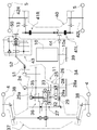
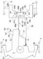
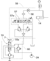
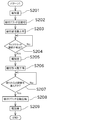
- the schematic diagram which shows the structure of a side clutch operation mechanism. It is a hydraulic circuit diagram of a rice transplanter. It is a control block diagram of raising / lowering of a planting part. It is a flowchart which shows the start process of the automatic raising / lowering control at the time of turning in a control part. It is a flowchart which shows the 1st pattern of automatic raising / lowering control at the time of turning.
- FIG. 1 is a side view of a riding rice transplanter 1 as an agricultural work vehicle according to an embodiment of the present invention.
- the riding rice transplanter 1 includes a vehicle body 2 and a planting part (work machine) 3 disposed behind the vehicle body 2.
- the vehicle body 2 includes a pair of left and right front wheels 4 and a pair of left and right rear wheels 5. Further, the vehicle body 2 includes a driver seat 6 between the front wheel 4 and the rear wheel 5 in the front-rear direction. In the vicinity of the driver seat 6, a steering handle (steering operation tool) 7 for performing a steering operation of the vehicle body 2, a speed change pedal 8 for adjusting the traveling speed of the vehicle body 2, and a forward / backward movement of the vehicle body 2 are switched. Various operation tools such as the forward / reverse switching lever 9 are arranged.
- an engine 10 is disposed below the driver seat 6, and a mission case 11 is disposed in front of the engine 10.
- a lifting link mechanism 12 for attaching the planting unit 3 a PTO shaft 13 for outputting the driving force of the engine 10 to the planting unit 3, and driving the planting unit 3 up and down.
- the elevating cylinder 14 is arranged.
- the vehicle body 2 includes a control unit.
- a control part consists of microcontrollers, for example, and is constituted so that each composition of rice transplanter 1 may be controlled based on signals, such as a sensor with which each part of rice transplanter 1 was equipped.
- the planting unit 3 includes a planting case 15, a plurality of floats 16, and a seedling stage 17.
- the lifting link mechanism 12 is connected to the planting case 15.
- the elevating link mechanism 12 has a parallel link structure including a top link 18, a lower link 19, and the like. By driving an elevating cylinder 14 connected to the lower link 19, the planting case 15 is moved up and down. It is comprised so that it can drive (Thereby, the planting part 3 whole can be raised / lowered up and down).
- the planting unit 20 is configured as a rotary planting device that includes two planting claws 22 in a rotating case 21.
- the planting case 15 receives a driving force of the engine 10 through the PTO shaft 13, and the rotating case 21 is rotationally driven by the driving force. Since the configuration of the rotary planting device is well known, detailed description is omitted, but by rotating the rotating case 21, the tip of the planting claw 22 is driven up and down while drawing a predetermined locus. It is configured. When the tip of the planting claw 22 moves from the top to the bottom, one seedling is scraped from the lower end of a seedling mat placed on a seedling mount 17 described later, and the root of the seedling is held. It is configured to move downward and to be implanted in the ground.
- the float 16 is provided symmetrically at the bottom of the planting part 3. By bringing the float 16 into contact with the ground, the planting unit 3 can be kept horizontal with respect to the ground, and the planting posture can be stabilized to perform accurate planting.
- a float sensor (grounding detector) (not shown) is attached to at least one of the plurality of floats 16 so that it can be detected whether or not the float 16 is in proper contact with the ground. It is configured. Based on the detection result of the float sensor, it can be determined whether or not the planting unit 3 has an appropriate height with respect to the ground. The detection result of the float sensor is output to the control unit.
- the seedling stage 17 is for mounting a large number of seedling mats (seedlings before planting), is made of reinforced plastic, and is inclined toward the rear.
- the seedling table 17 is supported above the planting case 15 by an upper guide rail 62 and a lower guide rail upper 63 so as to be reciprocally slidable in the left-right direction of the vehicle body.
- the planting part 3 is provided with a lateral feed mechanism (not shown) that reciprocates the seedling mounting platform 17 left and right within the range of the lateral width of the seedling mat. Thereby, the seedling mat placed on the seedling placing stand 17 can be moved relative to the planting unit 20 from side to side.
- the seedling mount 17 includes a seedling feeding belt (vertical feeding mechanism) that intermittently feeds the seedling mat downward (that is, toward the planting unit 20 side).
- a seedling feeding belt vertical feeding mechanism
- the planting part 3 is configured to be removable from the vehicle body 2. Specifically, the vehicle body 2 and the planting part 3 can be separated from each other by removing the connection between the lifting link mechanism 12 and the PTO shaft 13 and the planting part 3. . Further, other types of work machines (for example, weeding machines, grooving machines, etc.) can be attached to the vehicle body 2 from which the planting part 3 has been removed.
- the rice transplanter 1 of this embodiment is comprised as what is called a multipurpose rice transplanter.
- the rice transplanter 1 of this embodiment is provided with a not-illustrated notification unit.
- This notification unit is specifically configured as a buzzer, and its operation is controlled by the control unit.
- the engine 10 is disposed between the front wheel 4 and the rear wheel 5 in the front-rear direction of the vehicle body 2 and has a so-called midship layout. Further, the engine 10 is arranged at a substantially central portion in the left-right direction of the vehicle body 2 and is arranged so that the longitudinal direction of the drive output shaft (crankshaft) 10a is along the left-right direction of the vehicle body (so-called so-called). Horizontal placement).
- the drive output shaft 10a protrudes from the casing of the engine 10 toward the left side of the vehicle body.
- a drive transmission belt 34 is disposed at the left end of the drive output shaft 10a.
- the driving force of the engine 10 is input to the HMT (hydraulic mechanical continuously variable transmission) 25 disposed in the mission case 11 disposed in front of the engine 10 via the drive transmission belt 34.
- the HMT 25 includes an HST (hydrostatic continuously variable transmission) 26 and a planetary gear mechanism 27.
- the HST 26 has a configuration in which a variable displacement hydraulic pump 28 and a fixed displacement hydraulic motor 29 are connected by a hydraulic circuit.
- the variable displacement hydraulic pump 28 includes an input shaft 28a, which is a drive input shaft of the HST 26.
- the fixed displacement hydraulic motor 29 is provided with an output shaft 29a, which is a drive output shaft of the HST 26.
- the input shaft 28a of the variable displacement hydraulic pump 28 is disposed along the left-right direction of the vehicle body 2 and protrudes left and right from the housing of the HST 26.
- the drive transmission belt 34 is disposed at the left end of the input shaft 28a, and the output of the engine 10 is input thereto.
- a hydraulic pump 24 is connected to the right end of the input shaft 28a. That is, since the variable displacement hydraulic pump 28 and the hydraulic pump 24 are connected to the input shaft 28a, the input shaft 28a is rotationally driven by the driving force of the engine 10, so that the variable displacement hydraulic pump 28 and the hydraulic pump 24 are driven. Both are configured to be driven simultaneously.
- the oil discharged by driving the variable displacement hydraulic pump 28 is supplied to the fixed displacement hydraulic motor 29, and the output shaft 29a of the fixed displacement hydraulic motor 29 is driven to rotate. Further, the amount of oil discharged from the variable displacement hydraulic pump 28 can be changed in conjunction with the amount of operation of the shift pedal 8. Thereby, the rotation speed of the output shaft 29a of the fixed displacement hydraulic motor 29 can be changed steplessly by the operator operating the shift pedal 8.
- the hydraulic pump 24 will be described later.
- the planetary gear mechanism 27 includes a sun gear 30, a planetary carrier 32 that rotatably supports the planetary gear 31, and an outer gear 33.
- the planetary carrier 32 receives a driving force from the input shaft 28a of the variable displacement hydraulic pump 28 to which the driving force of the engine 10 is input.
- the sun gear 30 is fixed to the output shaft 29 a of the fixed displacement hydraulic motor 29.
- the outer gear 33 is fixed to the output shaft 25a of the HMT 25.
- the output of the engine 10 (rotation of the input shaft 28a) and the output of the HST 26 (rotation of the output shaft 29a) are combined in the planetary gear mechanism 27 and output from the output shaft 25a of the HMT 25.
- the output of the HST 26 can be steplessly changed according to the operation of the shift pedal 8
- the output of the HMT 25, which is a combination of the output of the HST 26 and the output of the engine 10 can also be changed steplessly.
- the output of the engine 10 can be changed steplessly according to the operation of the shift pedal 8 by the HMT 25.
- a part of the rotational driving force output from the output shaft 25a of the HMT 25 is input to the gear-type main transmission unit 36 via the main clutch 35 disposed in the mission case 11, and is appropriately shifted.
- the main transmission unit 36 includes a reverse gear (not shown) and is configured to be able to switch the vehicle body forward and backward. Then, the rotational driving force shifted by the main transmission unit 36 is output to the front axle case 37.
- the front axle case 37 is disposed in front of the mission case 11 and is formed integrally with the mission case 11.
- the rotational driving force from the main transmission unit 36 is transmitted to the left and right front axles 38, 38 disposed in the front axle case 37, and drives the left and right front wheels 4, 4.
- a part of the rotational driving force output from the main transmission unit 36 is taken out from the transmission case 11 and is transmitted to a rear axle case 40 located behind the engine 10 via a propeller shaft (driving wheel drive transmission shaft) 39. Communicated.
- FIG. 3 The details of the rear axle case 40 are shown in FIG. As shown in FIG. 3, the left and right rear axles 42 ⁇ / b> R and 42 ⁇ / b> L are both provided to protrude from the rear axle case 40.
- a rear wheel 5 is attached to the front ends of the rear axles 42R and 42L.
- the rotational driving force input into the rear axle case 40 is transmitted to the left rear axle 42L and the right rear axle 42R via a gear and a side clutch described later.
- the left rear axle 42L drives the right rear wheel 5, and the right rear axle 42R drives the right rear wheel 5.
- the rotational speeds of the front wheels 4 and the rear wheels 5 can be changed steplessly in accordance with the operation of the shift pedal 8. That is, the vehicle body 2 can be caused to travel at a desired vehicle speed when the operator operates the shift pedal 8.
- the left side clutch 41L is disposed between the drive transmission path from the propeller shaft 39 to the left rear axle 42L.
- a right side clutch 41R is disposed between the drive transmission path from the propeller shaft 39 to the right rear axle 42R.
- the left and right side clutches 41L and 41R can independently switch between connection and disconnection. Thereby, for example, when the vehicle body 2 performs a sharp turn, the transmission of the driving force to the inner rear wheel can be cut off, so that a smooth sudden turn can be realized.
- a rotation sensor 44 that detects the rotation of the propeller shaft 39 is attached to the propeller shaft 39.
- the detection result of the rotation sensor 44 is input to the control unit.
- the control unit the approximate distance traveled by the vehicle body 2 can be acquired by detecting the number of rotations of the propeller shaft 39 based on the detection result of the rotation sensor 44.
- a planting drive transmission shaft 52 is connected to the planting drive extraction portion 51 via a universal joint.
- the planting drive transmission shaft 52 is connected to a planting transmission 43 disposed behind the mission case 11.
- the planting transmission unit 43 is provided with a transmission composed of a plurality of gears, and is configured to appropriately shift the input driving force and output it from the PTO shaft 13.
- the planting part 3 is driven by the driving force transmitted by the PTO shaft 13.
- the driving force is transmitted to the PTO shaft 13 via the planting clutch 50.
- the planting clutch 50 is configured so that connection / disconnection can be switched by the control unit.
- the planting clutch 50 is also configured to be able to switch between connection / disconnection when an operator operates an unillustrated planting clutch operating tool.
- a planting clutch detection switch (not shown) for detecting whether the planting clutch 50 is on or off is disposed in the vicinity of the planting clutch 50. The detection result of the planting clutch detection switch is output to the control unit.
- FIG. 4 shows a schematic configuration of the side clutch operation mechanism 45.
- the side clutch operation mechanism 45 includes left and right clutch operation arms (clutch operation arms) 46L and 46R, a steering interlock lever (steering interlock lever) 47, and a steering operation transmission link 48.
- the clutch operation arms 46L and 46R are arranged outside the rear axle case 40.
- the clutch operation arms 46L and 46R are formed of elliptical plates and are fixed to one end of an arm shaft 67 arranged in the vertical direction.
- the arm shaft 67 is interlocked with the side clutches 41L and 41R, and is configured such that the side clutches 41L and 41R are turned on and off as the arm shaft 67 rotates. Therefore, by rotating the clutch operation arms 46L and 46R about the axis of the arm shaft 67, the corresponding side clutches 41L and 41R can be operated.
- the left clutch operation arm 46L is rotated to the “clutch connection position”
- the left side clutch 41L is connected, and the left clutch operation arm 46L is rotated to the “clutch disengagement position”.
- the left side clutch 41L is in a disconnected state.
- the right clutch operation arm 46R is rotated to the “clutch connection position”
- the right side clutch 41R is in the connected state, and when the right clutch operation arm 46R is rotated to the “clutch disengagement position”
- the side clutch 41R is configured to be in a disconnected state.
- the left and right clutch operating arms 46L and 46R are applied with an urging force by a not-illustrated urging member so as to be in the “clutch connection position”.
- the steering interlock lever 47 is disposed outside the rear axle case 40.
- the steering interlock lever 47 has a support shaft 47a attached to the center in the longitudinal direction thereof, and is configured to be rotatable about the support shaft 47a.
- the steering operation transmission link 48 is configured to transmit the operation of the steering handle 7 by the operator to the support shaft 47a of the steering interlocking lever 47. More specifically, the steering operation transmission link 48 includes a rod 48a and a rotating arm 48b.
- one end of the rotating arm 48b is fixed to the lower end of the support shaft 47a of the steering interlocking lever 47, and the other end is connected to the rod 48a.
- the rod 48 a is configured to move in the front-rear direction in accordance with the turning operation of the steering handle 7. With this configuration, when the rod 48a moves in the front-rear direction according to the operation of the steering handle 7, the support shaft 47a can be rotated via the rotation arm 48b. Thereby, the steering interlocking lever 47 is configured to rotate according to the operation amount of the steering handle 7.
- the steering interlock lever 47 is configured to be able to operate the left and right clutch operation arms 46L and 46R by rotating around the support shaft 47a. Specifically, it is as follows.
- the right clutch operation arm 46 ⁇ / b> R is disposed in the vicinity of the right end 47 c of the steering interlocking lever 47. Then, when the steering handle 7 is rotated clockwise by a certain amount or more, the right end 47c of the steering interlock lever 47 contacts the right clutch operation arm 46R, and the right clutch operation arm 46R is pushed and rotated.
- the left clutch operation arm 46L is disposed in the vicinity of the left end 47b of the steering interlock lever 47.
- the steering handle 7 is turned clockwise by a certain amount or more (when making a sudden turn to the right), the right clutch operation arm 46R is turned against the urging force, and the "clutch disengagement position" ". Further, by turning the steering handle 7 counterclockwise by a certain amount or more (when making a sudden turn to the left), the left clutch operation arm 46L is turned against the urging force, and the "clutch disengagement position” can do. In this way, when the steering handle 7 is operated to the right or left by a certain amount or more (when making a sudden turn), transmission of the driving force to the inner rear wheel 5 is cut off, and the field is roughened by the inner rear wheel 5. Smooth turning can be achieved while preventing this.
- steering interlocking lever 47 is configured to be in a neutral position (state shown in FIG. 4) in which neither of the left and right clutch operation arms 46L and 46R is operated.
- clutch sensors 49L and 49R are attached in the vicinity of the left and right clutch operation arms 46L and 46R, respectively.
- the clutch sensors 49L and 49R are specifically configured as switches. That is, when the clutch operating arms 46L and 46R are rotated to the “clutch disengagement position”, the clutch sensors 49L and 49R on the corresponding side are pressed and the switch is turned on to detect the disengagement of the side clutch. Has been. Thereby, it is possible to detect whether or not the side clutches 41L and 41R are connected with a simple configuration. The detection results of the clutch sensors 49L and 49R are input to the control unit.
- the hydraulic line is configured to supply pressure oil from the hydraulic pump 24 to the lift cylinder 14 via the power steering valve 55 and the lift control valve unit 56.
- the power steering valve 55 is a valve for switching the flow of oil that operates the power steering mechanism 60 provided in the vehicle body 2, and includes a spool 55 a that is driven according to the operation of the steering handle 7.
- the elevating control valve unit 56 is configured by combining the elevating control valve 57 and the stop valve 58 as one unit.
- the pressure oil sent from the hydraulic pump 24 via the power steering valve 55 passes through the lift control valve 57 and the stop valve 58 in this order, and then is supplied to the lift cylinder 14.
- the elevating control valve 57 is a solenoid valve for switching the driving direction of the elevating cylinder 14, and includes a spool 57a that is driven based on a control signal from the control unit. By changing the position of the spool 57a, the oil supply passage can be switched so that oil is supplied to the elevating cylinder 14 or discharged from the elevating cylinder 14.
- the control unit can drive the elevating cylinder 14 by appropriately controlling the elevating control valve 57 to raise or lower the planting unit 3.
- the stop valve 58 is a valve capable of blocking the oil flow between the elevating cylinder 14 and the elevating control valve 57, and is configured to be directly operated by the operator.
- the stop valve 58 is opened during normal operation so that oil from the elevation control valve 57 is supplied to the elevation cylinder 14.
- the stop valve 58 is closed as necessary. By closing the stop valve 58, oil can be prevented from flowing out of the elevating cylinder 14, so that the position of the planting portion 3 can be maintained even when the engine 10 is stopped.
- Float control is control which maintains the said planting part 3 at the appropriate height with respect to the ground by raising / lowering the planting part 3 following the unevenness
- the control is as follows. As described above, the detection result of the float sensor is input to the control unit.
- the control unit can determine whether or not the planting unit 3 is at an appropriate height with respect to the ground based on the detection result of the float sensor. When the control unit determines that the planting unit 3 is too high relative to the ground based on the detection result of the float sensor, the control unit lowers the planting unit 3 by operating the spool 57a of the elevation control valve 57. Further, when the control unit determines that the planting unit 3 is too low with respect to the ground based on the detection result of the float sensor, the control unit raises the planting unit 3 by operating the spool 57a of the elevation control valve 57. Let In addition, when the planting part 3 exists in suitable height with respect to the ground based on the detection result of a float sensor, a control part maintains the height of the said planting part 3. FIG.
- the planting part 3 can always be maintained at an appropriate height with respect to the ground, so that a seedling can be planted appropriately.
- the planting operation is continued by turning the vehicle body in a U-turn.
- the planting part 3 is in a position close to the ground, so if the vehicle body is turned in a U-turn in this state, the planting part 3 collides with a rod or the like. May cause damage. Therefore, the rice transplanter 1 according to the present embodiment automatically turns up when turning the vehicle body 2 U-turns during planting work until the planting unit 3 is sufficiently separated from the ground. It is comprised so that raising / lowering control may be performed.
- FIG. 6 shows a control block diagram for raising and lowering the planting part 3 of the rice transplanter 1.
- the control unit 64 monitors the rotation speed of the propeller shaft 39 detected by the rotation sensor 44.
- the controller 64 monitors the on / off state of the planting clutch 50 with the planting clutch detection switch 50a and the on / off state of the side clutch 41 (41L, 41R) with the clutch sensor 49 (49l, 49R). Further, the control unit 64 is configured to command the lowering of the planting unit 3.
- the storage unit 65 accumulates and stores the number of rotations measured by the rotation sensor 44 for a predetermined time, or stores a predetermined value, a correction value, and the like in advance. Perform these operations.
- ⁇ Automatic lift control during turning is started by detecting a predetermined operation of the operator as a trigger.
- the control unit of the present embodiment performs any one of the three triggers of “side clutch disconnection operation”, “planting clutch disconnection operation” and “reverse operation”.
- the control unit is configured to start automatic lifting control during turning.
- the control unit is configured to automatically select and execute one of the three control patterns depending on which of the three triggers is detected.
- This control pattern assumes a situation where the operator operates the steering handle 7 greatly to cause the vehicle body 2 to turn sharply (U-turn) during planting work.
- control unit When the control unit detects the disconnection of the side clutches 41L and 41R as a trigger based on the detection results of the clutch sensors 49L and 49R during the planting operation (conditional branch in S101), the control unit proceeds to S104 and performs the first control. Automatic lift control during turning is performed with a pattern (control of pattern 1).
- the rice transplanter 1 of the present embodiment is configured such that one of the side clutches 41L and 41R is disconnected only when the steering handle 7 is operated by a certain amount or more. Since it is configured in this way, it is detected by a simple sensor (specifically, a switch) called clutch sensors 49L and 49R that the operator has greatly operated the steering handle 7 to start the U-turn turning of the vehicle body 2. be able to. Therefore, in order to determine the start of the U-turn start, for example, an expensive rotation amount sensor for detecting the rotation amount of the steering shaft is not necessary, and the rice transplanter 1 can be configured easily and inexpensively.
- a simple sensor specifically, a switch
- the side clutches 41L and 41R are not disconnected. Therefore, in the delicate operation when the vehicle body 2 is moving straight, the automatic lifting control during turning is not started. Thereby, it is possible to prevent the automatic lifting / lowering control from starting at a timing that does not conform to the will of the operator.
- the control unit 64 When detecting the disconnection of the side clutches 41L and 41R (start of U-turn turning), the control unit 64 proceeds to S201 in FIG. 8 and makes a notification sound by the notification unit, and then disconnects the planting clutch 50 (S202). Then, the planting unit 3 is configured to rise (S203). As described above, when the start of the U-turn turning is detected, the planting unit 3 is automatically raised, so that it is possible to prevent the planting unit 3 from colliding with the eaves or the like when the vehicle body 2 is turned. . Moreover, since the planting clutch 50 is automatically disconnected when the planting unit 3 is lifted, useless operation of the planting unit 3 can be prevented. In addition, when raising the planting part 3, the said float control is interrupted.
- reporting part may alert
- the control unit 64 determines whether or not the side clutch whose disconnection is detected in S101 is connected again (S204). When the connection of the side clutch is detected, it means that the steering handle 7 has been returned to the neutral position, so that it can be determined that the U-turn turning has ended. In this case, the control unit 64 sounds a notification sound by the notification unit (S205), and then lowers the planting unit 3. Thus, even when the planting unit 3 is automatically lowered using the side clutch connection as a trigger, since the notification by the notification unit is performed in advance, the safety when automatically raising and lowering the planting unit 3 is improved. Can do.
- the control unit 64 detects the connection of the side clutch (the end of the U-turn turning), and then proceeds the distance corresponding to the approximately one vehicle, and then resumes planting. Is configured to do.
- the control unit 64 when detecting the connection of the side clutch (S204), the control unit 64 starts counting the number of rotations of the propeller shaft 39 based on the detection result of the rotation sensor 44. Then, it is determined whether or not the number of rotations is equal to or greater than the number of rotations corresponding to about one of the rice transplanters 1 (whether or not the vehicle has traveled the distance of about one unit) (S207). When the control unit determines that the vehicle body 2 has traveled a distance of about one of the rice transplanters 1, the control unit is configured to connect the planting clutch 50 (S208) and resume planting. .
- the timing for connecting the planting clutch 50 is determined based on the number of rotations of the propeller shaft.
- the offset distance is set to a distance corresponding to about one of the rice transplanters 1, but the offset distance varies depending on the turning performance of the vehicle body 2 and the like. Therefore, the rice transplanter 1 may be equipped with an adjustment dial for an operator to increase or decrease the offset distance.
- control part 64 is comprised so that when the planting clutch 50 is connected and planting is resumed, the float control is resumed and a notification sound is emitted by the notification unit (S209). Accordingly, since it is possible to notify the operator that planting has been resumed normally, it is possible to prevent a malfunction when, for example, planting has not been resumed for some reason.
- This control pattern assumes a situation in which the operator cuts the planting clutch during planting work, interrupts planting, travels straight ahead for a short distance, and then turns the vehicle body 2 suddenly (U-turn). Yes. Such an operation is performed, for example, when a certain section is not planted in order to secure a space for the rice transplanter 1 to escape from the field in the row.
- the planting clutch 50 When the planting clutch 50 is disconnected by operating the planting clutch operating arm (not shown), the transmission of the driving force from the PTO shaft 13 to the planting case 15 is cut off. Further, when the planting clutch 50 is disconnected, the planting clutch detection switch 50a provided adjacent to the planting clutch 50 is turned OFF, and this is detected by the control unit 64 as a trigger (conditional branching in S102). In this case, the control unit 64 proceeds to S105 and performs automatic elevation control with the second control pattern (control of pattern 2).
- the control unit 64 is configured to first sound a notification sound (S301), and then interrupt the float control to raise the planting unit 3 (S203). Subsequently, the control unit starts a process of counting the number of rotations of the propeller shaft 39 based on the detection result of the rotation sensor 44 (S303), and detects the disconnection of the side clutches 41L and 41R (start of U-turn turning) (S304). When the determination is made, the counting is finished (S305). Thereby, as shown in FIG. 12, it is possible to acquire the distance (advance distance) that the vehicle body 2 has advanced between the time when planting is interrupted and the time when U-turn turning is started.
- the control unit 64 After detecting the engagement of the side clutch (end of U-turn turning), the control unit 64 counts the number of rotations of the propeller shaft 39 based on the detection result of the rotation sensor 44, and the vehicle body 2 corresponds to the deviation. It is determined whether or not the vehicle has traveled for a distance (S309). Then, after determining that the vehicle body 2 has traveled a distance corresponding to the deviation, the planting clutch 50 is connected (S310). In addition, when the planting clutch 50 is connected, the control unit 64 is configured to resume float control and resume planting, and to sound a notification sound by the notification unit (S311).
- This control pattern assumes a situation in which the operator turns the vehicle body 2 rapidly after turning the vehicle body 2 backward during planting work. Such an operation is performed, for example, when it is desired to perform planting up to the position of the last minute.
- control unit 64 When the control unit 64 detects that the operator has started the reverse movement of the vehicle body 2 by operating the forward / reverse switching lever (conditional branch in S103), the control unit 64 proceeds to S106 and performs the third control pattern (pattern 3). Control).
- control unit 64 is configured to sound a notification sound (S401), disengage the planting clutch 50 (S402), interrupt the float control, and raise the planting unit 3 (S403). . Subsequently, the control unit 64 starts a process of counting the number of rotations of the propeller shaft 39 based on the detection result of the rotation sensor 44 (S404), and detects the disconnection of the side clutches 41L and 41R (start of U-turn turning) ( When the determination is made at S405, the counting is finished (S406). As a result, as shown in FIG. 13, it is possible to acquire a distance (reverse distance) that the vehicle body 2 has moved backward from the start of reverse travel to the start of U-turn turning.
- control unit 64 detects that the side clutch whose disconnection is detected in S405 is connected again (end of U-turn turning) (determination in S407), the control unit 64 sounds a notification sound (S408). Then, the planting part 3 is lowered (S409). At this time, as shown in FIG. 13, when the vehicle starts moving backward (when the planting is interrupted) and immediately after completing the U-turn turning, There is a deviation corresponding to (offset distance corresponding to approximately one machine 1)-(reverse distance).
- the control unit 64 After detecting the engagement of the side clutch (end of U-turn turning), the control unit 64 counts the number of rotations of the propeller shaft 39 based on the detection result of the rotation sensor 44, and the vehicle body 2 corresponds to the deviation. It is determined whether or not the vehicle has traveled for a distance (S410). Then, after determining that the vehicle body 2 has traveled a distance corresponding to the deviation, the planting clutch 50 is connected (S411). In addition, when the planting clutch 50 is connected, the control unit resumes the float control and resumes planting, and the notification unit sounds a notification sound (S412).
- the rice transplanter 1 As described above, the rice transplanter 1 according to the present embodiment must be notified by the notification unit before automatically raising or lowering the planting unit 3 in any of the three control patterns of the automatic lifting control during turning. Is configured to do. Thereby, the safety
- the detection result of the rotation sensor 44 is taken into consideration. You may comprise so that the end of U-turn turning may be judged. For example, if the side clutch 41 is connected after the side clutch 41 is disconnected and the vehicle body 2 does not travel a sufficient distance, it can be determined that the turning operation has been completed without completing the U-turn turning. When the U-turn turning is not completed in this way, it is considered that the operator does not turn with the intention of continuing the planting operation. Therefore, even if the side clutch 41 is connected, the planting unit It is better not to perform the automatic lowering of 3.
- the control unit 64 counts the number of rotations of the propeller shaft 39 by the rotation sensor 44, and until the number of rotations reaches a predetermined number or more, U It can be configured that the planting part 3 is not automatically lowered by judging that the turn is not completed.
- the control unit 64 when the control unit 64 detects that the operator has started the reverse movement of the vehicle body 2 by operating the forward / reverse switching lever, the control unit 64 notifies the notification unit by the notification unit. It is comprised so that the planting part 3 may be raised after sounding. Thus, also in the case of the automatic raising control of the planting unit 3 at the time of reverse travel, since the notification is performed before the planting unit 3 is automatically lifted, safety can be improved.
- the rice transplanter 1 of this embodiment is comprised so that the planting part 3 can be removed as mentioned above.
- work which attaches the planting part 3 or another working machine with respect to the vehicle body 2 of the state which removed the planting part 3 is performed as follows, for example. That is, a work machine to be attached to the vehicle body 2 is installed on the ground or an appropriate table behind the vehicle body 2. Then, the vehicle body 2 is moved backward while the lifting link mechanism 12 is maintained at an appropriate height, and the lifting link mechanism 12 is brought close to the connection point of the work implement to connect the lift link mechanism and the work implement.
- the rice transplanter 1 includes an appropriate sensor that detects whether or not the work machine is attached to the vehicle body 2. When the work machine is not attached, the rice transplanter 1 automatically moves up and down during reverse travel. It is configured not to perform control.
- the rice transplanter 1 of the present embodiment includes a manual lift switch (not shown) configured so that the height of the planting unit 3 can be manually adjusted by an operator. Yes.
- the control unit 64 is configured to drive the elevating cylinder 14 to drive the planting unit 3 up and down, and to shift to the standby mode and interrupt the float control.
- the planting operation can be resumed quickly by performing a predetermined operation. Therefore, in the rice transplanter 1 of the present embodiment, when the operator performs an operation of connecting the planting clutch 50 during the standby mode, the control unit 64 exits the standby mode and makes a notification sound by the notification unit. Thereafter, the float control is resumed. When the float control is resumed, the planting unit 3 is automatically raised and lowered to the position before the operator changes the height, so that the planting operation can be appropriately resumed. Thus, the planting operation can be resumed quickly only by the operation of connecting the planting clutch 50.
- notification is performed by the notification unit. That is, when the float control is resumed from the state where the height of the planting unit 3 is changed, the planting unit 3 is automatically raised and lowered to the original height, so it is preferable to notify the surroundings of the automatic elevation. .
- the notification unit by performing the notification before resuming the float control as described above, it is possible to notify the surroundings that the planting unit 3 is automatically raised and lowered, and the safety can be improved.
- the rice transplanter 1 includes the side clutches 41L and 41R, the side clutch operation mechanism 45, the clutch sensors 49L and 49R, the elevating cylinder 14, the control unit 64, and the planting clutch. 50.
- the side clutches 41L and 41R can switch the presence or absence of transmission of driving force from the engine 10 to the axles of the left and right rear wheels 5 and 5.
- the side clutch operating mechanism 45 disconnects the side clutches 41L and 41R.
- the clutch sensors 49L and 49R can detect the operating state of the side clutches 41L and 41R.
- the lifting cylinder 14 drives the planting part 3 up and down.
- the control unit 64 controls driving of the elevating cylinder 14.
- the planting clutch 50 can switch whether or not the driving force is transmitted to the planting unit 3.
- the control unit can perform the following automatic lifting control during turning. That is, when the control unit detects disconnection of the planting clutch 50 during operation of the planting unit 3, the control unit raises the planting unit 3, and stores the advance distance from when the planting clutch 50 is disconnected until the start of turning. To do. Moreover, the said control part will determine with turning start, if the cutting
- the control unit can perform the following turning self-automatic elevation control. That is, when the control unit detects the backward operation of the vehicle body 2 during the operation of the planting unit, the control unit raises the planting unit and measures the backward distance from the start of the reverse travel to the start of the turn. Further, the control unit determines that the turn is started when it detects the disconnection of the side clutch. Moreover, if a control part detects the connection of a side clutch, based on this, it will determine with the end of turning, and will lower a planting part. When the control unit detects that the vehicle has traveled a distance obtained by subtracting the reverse travel distance from the predetermined offset distance after the turn, the planting clutch 50 is connected.
- the rice transplanter 1 can be configured easily and inexpensively as compared with the configuration in which the operation amount of the steering operation tool is detected by the potentiometer. As described above, by measuring the movement distance until the turn starts, the work can be resumed at an appropriate position after the turn is completed.
- the rice transplanter 1 of the present embodiment is configured as follows. That is, the side clutch operating mechanism 45 is linked to the left clutch operating arm 46L for operating the left side clutch 41L, the right clutch operating arm 46R for operating the right side clutch 41R, and the operation of the steering handle 7. And a steering interlocking lever 47 that rotates about an axis.
- the left clutch operating arm 46L is disposed in the vicinity of the left end 47b of the steering interlocking lever 47.
- the right clutch operation arm 46R is disposed in the vicinity of the right end 47c of the steering interlock lever 47.
- the clutch sensor includes a left clutch sensor 49L that detects the movement of the left clutch operation arm 46L, and a right clutch sensor 49L that detects the movement of the right clutch operation arm 46R.
- the rice transplanter 1 of the present embodiment is configured as follows. That is, the rice transplanter 1 includes a rotation sensor 44 that detects the number of rotations of the propeller shaft 39 that transmits driving force to the rear wheel axle on the upstream side of the side clutches 41L and 41R. The control unit acquires the movement distance based on the detection value of the rotation sensor 44.
- the planting clutch 50 is compared with the conventional method using the rotational speed of the inner axle where there is a fear of slipping.
- the control unit can accurately determine the timing for connecting.
- the clutch sensors 49L and 49R are proximity switches, and the control unit recognizes whether the side clutches 41L and 41R are turned on or off by detecting the ON or OFF of the proximity clutch. It is preferable.
- the rice transplanter 1 of this embodiment is provided with the alerting
- control unit determines the end of the turn in consideration of the number of times the propeller shaft 39 of the rear wheel has rotated in addition to the detection of the connection of the side clutch. It can also be configured.
- the end of turning can be determined more accurately by considering the number of rotations of the propeller shaft 39.
- the rice transplanter that can implement the three patterns of automatic lifting control during turning from pattern 1 to pattern 3 and can switch the three patterns according to the situation has been described.
- the agricultural work vehicle need not be able to realize all these three control patterns, and may have a configuration capable of realizing only one or two control patterns.
- the HMT 25 including the HST 26 and the planetary gear mechanism 27 is arranged in the transmission case 11 as a continuously variable transmission.
- the continuously variable transmission may include only the HST 26.
- the HMT combining the HST and the planetary gear mechanism is more advantageous from the viewpoint of transmission efficiency than the configuration of only the HST.
- the clutch sensor is described as a switch, but the present invention is not limited to this. Any other type of sensor can be adopted as long as it can detect that the clutch operating arm has been operated.
- the planting unit 3 is a rotary planting unit, but may be a crank type.
- the notification unit is not limited to a buzzer, and may be configured to make an announcement such as “the planting unit will rise” by means of a machine sound or the like.
- the notification by the notification unit is not limited to sound, and may be configured to turn on an alarm lamp, for example.
- the control is performed to disconnect the planting clutch after notification, but the notification is performed after the planting clutch is disconnected. It may be configured. In short, what is necessary is just to be able to alert
- the offset distance is set to the distance of about one of the rice transplanters 1, but in addition to this, the offset distance is set according to the soil quality of the paddy field (whether the soil is highly viscous, etc.). You may comprise so that it can increase / decrease.
- the clutch sensors 49L and 49R may be attached to the outside of the rear axle case, or may be attached to the inside of the rear axle case.
- FIG. 4 shows an example in which the clutch sensors 49L and 49R are provided outside the rear axle case.
- FIG. 3C shows an example in which the right clutch sensor 49R is arranged inside the rear axle case.
- one end of an elliptical arm 68 is fixed to one end of the arm shaft 67 of the right clutch operation arm 46R, and the right clutch sensor 49R is disposed in the vicinity of the arm 68.
- the right clutch sensor 49R is provided so as to come into contact with the arm 68 when the arm 68 rotates.
- the clutch operation arm 46R is rotated, the arm 68 is also rotated integrally and the clutch sensor 49R is turned on, so that the rotation of the clutch operation arm 46R can be detected by the clutch sensor 49R.
- the clutch sensor may not be in direct contact with the clutch operation arm.
- the configuration of the present invention is not limited to the rice transplanter but can be applied to other agricultural work vehicles provided with working machines that move up and down.
Landscapes
- Life Sciences & Earth Sciences (AREA)
- Engineering & Computer Science (AREA)
- Soil Sciences (AREA)
- Environmental Sciences (AREA)
- Mechanical Engineering (AREA)
- Chemical & Material Sciences (AREA)
- Combustion & Propulsion (AREA)
- Transportation (AREA)
- Guiding Agricultural Machines (AREA)
- Transplanting Machines (AREA)
- Lifting Devices For Agricultural Implements (AREA)
Abstract
Description
2 車体
3 植付部(作業機)
7 ステアリングハンドル(操向操作具)
14 昇降シリンダ
41L,41R サイドクラッチ
49L,49R クラッチセンサ
Claims (7)
- 左右の後輪の車軸に対する駆動力の伝達の有無を切換可能なサイドクラッチと、
前記サイドクラッチを切断するサイドクラッチ操作機構と、
前記サイドクラッチの作動状況を検出可能なクラッチセンサと、
作業機を昇降駆動するための昇降シリンダと、
前記昇降シリンダの駆動を制御する制御部と、
前記作業機に対する駆動力の伝達の有無を切換可能な作業クラッチと、
を備え、
前記制御部は、
前記作業機の作動中に前記作業クラッチの切断を検出すると、前記作業機を上昇させ、
前記作業クラッチが切断されてから旋回開始までの移動距離を測定し、
前記サイドクラッチの切断を検出すると旋回開始と判定し、
前記サイドクラッチの接続を検出すると、これに基づいて旋回終了と判定して前記作業機を下降させ、
前記旋回終了後に、前記移動距離と所定のオフセット距離を加算した距離を走行したことを検出すると、前記作業クラッチを接続する旋回時自動昇降制御が可能であることを特徴とする農業用作業車両。 - 作業機の作動中に車体の後進操作を検出すると、前記作業機を上昇させ、
前記後進を開始してから旋回開始までの移動距離を測定し、
サイドクラッチの切断を検出すると旋回開始と判定し、
前記サイドクラッチの接続を検出すると、これに基づいて旋回終了と判定して前記作業機を下降させ、
前記旋回終了後に、所定のオフセット距離から前記移動距離を減算した距離を走行したことを検出すると、前記作業クラッチを接続する旋回時自動昇降制御が可能な制御部を備えることを特徴とする農業用作業車両。 - 請求項1又は2に記載の農業用作業車両であって、
操向操作具が所定の操作量以上操作された場合に、前記サイドクラッチを切断するサイドクラッチ操作機構と、
前記サイドクラッチの作動状況を検出可能なクラッチセンサと、
を備え、
前記サイドクラッチ操作機構は、
左のサイドクラッチを操作する左クラッチ操作部材と、
右のサイドクラッチを操作する右クラッチ操作部材と、
操向操作具の操作に連動して軸を中心に回動する操向連動レバーと、
を備え、
前記左クラッチ操作部材は前記操向連動レバーの車体左側端部近傍に配置され、
前記右クラッチ操作部材は前記操向連動レバーの車体右側端部近傍に配置され、
前記操向操作具が左右の何れかに所定量操作されると、左クラッチ操作部材又は右クラッチ操作部材を操向連動レバーが押すことにより、対応する側のサイドクラッチが切断されるように構成されており、
前記クラッチセンサは、
前記左クラッチ操作部材の動きを検出する左クラッチセンサと、
前記右クラッチ操作部材の動きを検出する右クラッチセンサと、
から構成されていることを特徴とする農業用作業車両。 - 請求項1又は2に記載の農業用作業車両であって、
前記後輪の車軸へと駆動力を伝達する駆動軸の回転数を検出する回転センサを、前記サイドクラッチの上流側に備え、
前記制御部は、前記回転センサの検出値に基づいて前記移動距離を取得することを特徴とする農業用作業車両。 - 請求項3に記載の農業用作業車両であって、
前記クラッチセンサは近接スイッチであり、
前記制御部は、前記近接クラッチのON又はOFFを検出することにより、前記サイドクラッチの入り切りを認知することを特徴とする農業用作業。 - 請求項1に記載の農業用作業車両であって、
前記作業機の昇降時、及び前記作業クラッチの接続時に報知を行う報知部を備えることを特徴とする農業用作業車両。 - 請求項1又は2に記載の農業用作業車両であって、
前記制御部は、
前記サイドクラッチの接続の検出に加えて、
前記後輪のドライブシャフトが回転した回数を考慮して、前記旋回終了の判定を行うことを特徴とする農業用作業車両。
Priority Applications (2)
| Application Number | Priority Date | Filing Date | Title |
|---|---|---|---|
| CN201180013866.0A CN102802400B (zh) | 2010-03-15 | 2011-03-10 | 农业用作业车辆 |
| KR1020127023814A KR101524578B1 (ko) | 2010-03-15 | 2011-03-10 | 농업용 작업 차량 |
Applications Claiming Priority (4)
| Application Number | Priority Date | Filing Date | Title |
|---|---|---|---|
| JP2010058155A JP5508073B2 (ja) | 2010-03-15 | 2010-03-15 | 農業用作業車両 |
| JP2010058031A JP5702543B2 (ja) | 2010-03-15 | 2010-03-15 | 乗用田植機 |
| JP2010-058155 | 2010-03-15 | ||
| JP2010-058031 | 2010-03-15 |
Publications (1)
| Publication Number | Publication Date |
|---|---|
| WO2011114671A1 true WO2011114671A1 (ja) | 2011-09-22 |
Family
ID=44648786
Family Applications (1)
| Application Number | Title | Priority Date | Filing Date |
|---|---|---|---|
| PCT/JP2011/001424 Ceased WO2011114671A1 (ja) | 2010-03-15 | 2011-03-10 | 農業用作業車両 |
Country Status (3)
| Country | Link |
|---|---|
| KR (1) | KR101524578B1 (ja) |
| CN (1) | CN102802400B (ja) |
| WO (1) | WO2011114671A1 (ja) |
Cited By (4)
| Publication number | Priority date | Publication date | Assignee | Title |
|---|---|---|---|---|
| CN106068835A (zh) * | 2016-06-30 | 2016-11-09 | 程虎 | 一种多功能自动排淤泥的插秧机驱动装置 |
| WO2019138789A1 (ja) * | 2018-01-11 | 2019-07-18 | ヤンマー株式会社 | 作業車両 |
| JP2019122359A (ja) * | 2018-01-11 | 2019-07-25 | ヤンマー株式会社 | 作業車両 |
| JP2020137463A (ja) * | 2019-02-28 | 2020-09-03 | ヤンマーパワーテクノロジー株式会社 | 自律走行システム |
Families Citing this family (10)
| Publication number | Priority date | Publication date | Assignee | Title |
|---|---|---|---|---|
| KR102317483B1 (ko) * | 2014-05-19 | 2021-10-28 | 주식회사 대동 | 승용형 이앙기 사이드 클러치 작동구조 |
| CN105144936A (zh) * | 2015-10-19 | 2015-12-16 | 苏州市天幕景观装饰工程有限公司 | 一种插秧机 |
| JP6689126B2 (ja) * | 2016-04-26 | 2020-04-28 | ヤンマー株式会社 | 作業車両制御システム |
| JP6663382B2 (ja) * | 2017-03-24 | 2020-03-11 | ヤンマー株式会社 | 作業車両 |
| JP6881233B2 (ja) * | 2017-10-27 | 2021-06-02 | 井関農機株式会社 | 作業車両 |
| JP6673326B2 (ja) * | 2017-12-27 | 2020-03-25 | 井関農機株式会社 | 作業車両 |
| CN110691878B (zh) * | 2018-03-27 | 2021-08-31 | 株式会社小松制作所 | 作业车辆 |
| WO2020003563A1 (ja) * | 2018-06-25 | 2020-01-02 | 株式会社クボタ | 作業車両 |
| JP7027268B2 (ja) * | 2018-06-25 | 2022-03-01 | 株式会社クボタ | 作業車両 |
| CN109729792A (zh) * | 2019-01-04 | 2019-05-10 | 丰疆智慧农业股份有限公司 | 智能插秧机及其自动换挡方法 |
Citations (4)
| Publication number | Priority date | Publication date | Assignee | Title |
|---|---|---|---|---|
| JP2003102214A (ja) * | 2001-09-27 | 2003-04-08 | Kubota Corp | 田植機 |
| JP2007050796A (ja) * | 2005-08-18 | 2007-03-01 | Yanmar Co Ltd | 乗用型田植機のサイドクラッチ切換機構 |
| JP2007104980A (ja) * | 2005-10-14 | 2007-04-26 | Mitsubishi Agricult Mach Co Ltd | 移植機 |
| JP2008228586A (ja) * | 2007-03-16 | 2008-10-02 | Kubota Corp | 作業車 |
Family Cites Families (3)
| Publication number | Priority date | Publication date | Assignee | Title |
|---|---|---|---|---|
| CN86208295U (zh) * | 1986-10-30 | 1987-09-23 | 广西南宁插秧机厂 | 机动插秧机 |
| CN1063011A (zh) * | 1991-01-09 | 1992-07-29 | 南京农业大学农业工程、乡镇企业学院 | 播秧机 |
| JP2001151130A (ja) * | 1999-11-29 | 2001-06-05 | Iseki & Co Ltd | 作業車両の操向制御装置 |
-
2011
- 2011-03-10 WO PCT/JP2011/001424 patent/WO2011114671A1/ja not_active Ceased
- 2011-03-10 KR KR1020127023814A patent/KR101524578B1/ko active Active
- 2011-03-10 CN CN201180013866.0A patent/CN102802400B/zh not_active Expired - Fee Related
Patent Citations (4)
| Publication number | Priority date | Publication date | Assignee | Title |
|---|---|---|---|---|
| JP2003102214A (ja) * | 2001-09-27 | 2003-04-08 | Kubota Corp | 田植機 |
| JP2007050796A (ja) * | 2005-08-18 | 2007-03-01 | Yanmar Co Ltd | 乗用型田植機のサイドクラッチ切換機構 |
| JP2007104980A (ja) * | 2005-10-14 | 2007-04-26 | Mitsubishi Agricult Mach Co Ltd | 移植機 |
| JP2008228586A (ja) * | 2007-03-16 | 2008-10-02 | Kubota Corp | 作業車 |
Cited By (13)
| Publication number | Priority date | Publication date | Assignee | Title |
|---|---|---|---|---|
| CN106068835A (zh) * | 2016-06-30 | 2016-11-09 | 程虎 | 一种多功能自动排淤泥的插秧机驱动装置 |
| KR20200107923A (ko) * | 2018-01-11 | 2020-09-16 | 얀마 파워 테크놀로지 가부시키가이샤 | 작업 차량 |
| WO2019138789A1 (ja) * | 2018-01-11 | 2019-07-18 | ヤンマー株式会社 | 作業車両 |
| JP2019122359A (ja) * | 2018-01-11 | 2019-07-25 | ヤンマー株式会社 | 作業車両 |
| KR102741765B1 (ko) | 2018-01-11 | 2024-12-11 | 얀마 파워 테크놀로지 가부시키가이샤 | 작업 차량 |
| CN113194708A (zh) * | 2019-02-28 | 2021-07-30 | 洋马动力科技有限公司 | 自主行驶系统 |
| WO2020174839A1 (ja) * | 2019-02-28 | 2020-09-03 | ヤンマー株式会社 | 自律走行システム |
| JP7137270B2 (ja) | 2019-02-28 | 2022-09-14 | ヤンマーパワーテクノロジー株式会社 | 自律走行システム |
| JP2022167991A (ja) * | 2019-02-28 | 2022-11-04 | ヤンマーパワーテクノロジー株式会社 | 自律走行システム |
| EP3932159A4 (en) * | 2019-02-28 | 2022-12-07 | Yanmar Power Technology Co., Ltd. | AUTONOMOUS DRIVING SYSTEM |
| JP2020137463A (ja) * | 2019-02-28 | 2020-09-03 | ヤンマーパワーテクノロジー株式会社 | 自律走行システム |
| JP7734120B2 (ja) | 2019-02-28 | 2025-09-04 | ヤンマーパワーテクノロジー株式会社 | 自律走行システム |
| US12498721B2 (en) | 2019-02-28 | 2025-12-16 | Yanmar Power Technology Co., Ltd. | Autonomous traveling system for working vehicle to travel autonomously |
Also Published As
| Publication number | Publication date |
|---|---|
| KR20120127496A (ko) | 2012-11-21 |
| CN102802400A (zh) | 2012-11-28 |
| CN102802400B (zh) | 2015-10-21 |
| KR101524578B1 (ko) | 2015-06-01 |
Similar Documents
| Publication | Publication Date | Title |
|---|---|---|
| KR101524578B1 (ko) | 농업용 작업 차량 | |
| JP5689739B2 (ja) | 田植機 | |
| JP2014144008A (ja) | 農業用作業車両 | |
| JP4367029B2 (ja) | 農作業車 | |
| JP5267501B2 (ja) | 乗用型作業機 | |
| JP2017113023A (ja) | 苗移植機 | |
| JP5508073B2 (ja) | 農業用作業車両 | |
| CN103416138B (zh) | 苗移植机 | |
| JP2005198594A (ja) | 苗植機の苗植昇降制御装置 | |
| JP5678851B2 (ja) | 苗移植機 | |
| JP5888613B2 (ja) | 苗移植機 | |
| JP2011188824A (ja) | 乗用型田植機 | |
| JP4710396B2 (ja) | 乗用型作業機 | |
| JP2004222604A (ja) | 作業車 | |
| JP5751314B2 (ja) | 乗用型苗移植機 | |
| JP2019004891A (ja) | 作業機 | |
| JP2013066391A5 (ja) | ||
| JP5457895B2 (ja) | 乗用型田植機 | |
| JP2011115170A (ja) | 乗用型苗移植機 | |
| JP5110100B2 (ja) | 田植機 | |
| JP2015156876A (ja) | 苗移植機 | |
| JP6485113B2 (ja) | 作業機 | |
| JP2016019540A (ja) | 苗移植機 | |
| JP3807880B2 (ja) | 水田作業機 | |
| JP5761475B2 (ja) | 苗移植機 |
Legal Events
| Date | Code | Title | Description |
|---|---|---|---|
| WWE | Wipo information: entry into national phase |
Ref document number: 201180013866.0 Country of ref document: CN |
|
| 121 | Ep: the epo has been informed by wipo that ep was designated in this application |
Ref document number: 11755864 Country of ref document: EP Kind code of ref document: A1 |
|
| ENP | Entry into the national phase |
Ref document number: 20127023814 Country of ref document: KR Kind code of ref document: A |
|
| NENP | Non-entry into the national phase |
Ref country code: DE |
|
| 122 | Ep: pct application non-entry in european phase |
Ref document number: 11755864 Country of ref document: EP Kind code of ref document: A1 |