WO2011105232A1 - 動力工具 - Google Patents
動力工具 Download PDFInfo
- Publication number
- WO2011105232A1 WO2011105232A1 PCT/JP2011/052939 JP2011052939W WO2011105232A1 WO 2011105232 A1 WO2011105232 A1 WO 2011105232A1 JP 2011052939 W JP2011052939 W JP 2011052939W WO 2011105232 A1 WO2011105232 A1 WO 2011105232A1
- Authority
- WO
- WIPO (PCT)
- Prior art keywords
- unit
- operation member
- activation
- lock
- user
- Prior art date
Links
Images


Classifications
-
- B—PERFORMING OPERATIONS; TRANSPORTING
- B25—HAND TOOLS; PORTABLE POWER-DRIVEN TOOLS; MANIPULATORS
- B25F—COMBINATION OR MULTI-PURPOSE TOOLS NOT OTHERWISE PROVIDED FOR; DETAILS OR COMPONENTS OF PORTABLE POWER-DRIVEN TOOLS NOT PARTICULARLY RELATED TO THE OPERATIONS PERFORMED AND NOT OTHERWISE PROVIDED FOR
- B25F5/00—Details or components of portable power-driven tools not particularly related to the operations performed and not otherwise provided for
- B25F5/02—Construction of casings, bodies or handles
-
- A—HUMAN NECESSITIES
- A01—AGRICULTURE; FORESTRY; ANIMAL HUSBANDRY; HUNTING; TRAPPING; FISHING
- A01G—HORTICULTURE; CULTIVATION OF VEGETABLES, FLOWERS, RICE, FRUIT, VINES, HOPS OR SEAWEED; FORESTRY; WATERING
- A01G3/00—Cutting implements specially adapted for horticultural purposes; Delimbing standing trees
- A01G3/04—Apparatus for trimming hedges, e.g. hedge shears
- A01G3/047—Apparatus for trimming hedges, e.g. hedge shears portable
- A01G3/053—Apparatus for trimming hedges, e.g. hedge shears portable motor-driven
Definitions
- the present invention relates to a power tool, and more particularly to a power tool that can change the position and orientation of a handle with respect to the tool.
- Japanese Patent Laid-Open No. 3-117573 discloses a power tool that can change the direction of the handle relative to the tool.
- the main body has a first unit and a second unit that is rotatable with respect to the first unit.
- a tool is attached to the first unit, and a handle that is gripped by a user is provided on the second unit. The user can adjust the position and orientation of the handle with respect to the tool by rotating the second unit relative to the first unit.
- a power tool of the same kind is also disclosed in German Patent No. 19532299.
- the power tool described above further includes an activation operation member, a lock operation member, and an interlock mechanism.
- the drive operation member is an operation switch operated by the user in order to drive the tool by the prime mover.
- the lock operation member is an operation switch operated by the user in order to release the lock between the first unit and the second unit.
- the interlock mechanism mechanically prohibits both the activation operation member and the lock operation member from being operated.
- the technology disclosed in the present specification aims to improve the operability of a power tool capable of adjusting the position and orientation of a handle with respect to the tool.
- the power tool includes a tool and a main body that drives the tool with a prime mover.
- the main body includes a first unit and a second unit rotatable with respect to the first unit.
- a tool is attached to the first unit, and a handle that is gripped by a user is provided on the second unit.
- the position and orientation of the handle relative to the tool can be adjusted by rotating the second unit relative to the first unit.
- the power tool further includes a start operation member and a start interlock switch.
- the activation operation member is operated between the activation position and the stop position by the user.
- the start interlock switch is provided on a supply path for supplying energy to the prime mover. When the activation operation member is at the activation position, the activation interlock switch conducts the supply path, and when the activation operation member is at the stop position, the activation interlock switch interrupts the supply path. Accordingly, the prime mover drives and stops the tool in accordance with the operation on the activation operation member.
- the power tool further includes a lock operating member and a lock interlock switch.
- the lock operation member is operated between the lock position and the unlock position by the user.
- the lock operating member prohibits rotation of the second unit relative to the first unit when in the locked position, and allows rotation of the second unit relative to the first unit when in the unlocked position.
- the lock interlock switch is provided on the aforementioned supply path. When the lock operation member is in the lock position, the lock interlock switch conducts the supply path, and when the lock operation member is in the unlock position, the lock interlock switch interrupts the supply path.
- the lock interlock switch prohibits energy supply to the prime mover.
- the prime mover is a motor
- the power supply to the motor is cut off.
- the prime mover is an engine
- the fuel supply to the engine is cut off. Therefore, while the lock operation member is in the unlock position, even if the activation operation member is operated to the activation position, the driving of the tool by the prime mover is prohibited.
- the user may unintentionally apply an operating force to the activation operation member provided on the handle.
- the lock operation member is in the unlock position
- the drive of the tool is prohibited by the lock interlock switch regardless of the position of the activation operation member.
- the activation operation member is operated to the activation position
- the tool is unintentionally driven by the prime mover when the lock operation member is returned to the lock position after adjusting the handle.
- the activation operation member while the lock operation member is in the unlock position, even if the user applies a force to the activation operation member, the activation operation member is prevented from being operated to the activation position. However, if the lock operation member is returned to the lock position while the user is applying force to the activation operation member, the activation operation member is immediately operated to the activation position, and the tool is driven by the prime mover. .
- the power tool preferably has the following interlock mechanism.
- the interlock mechanism allows the activation operation member to move from the stop position to the activation position when the lock operation member is in the unlock position, and locks the operation member when the activation operation member is in the activation position. Is prohibited from moving to the locked position.
- this interlock mechanism allows the activation operation member to move to the activation position even when the lock operation member is in the unlock position. That is, when the user applies a force to the activation operation member, the activation operation member is operated to the activation position. In addition, when the activation operation member is in the activation position, the lock operation member is prohibited from moving to the lock position.
- the lock operation member is prohibited from being operated to the lock position. Since the user cannot return the lock operation member to the lock position, the user can recognize that the activation operation member is being operated to the operation position unintentionally. The user can return the activation operation member to the stop position and then operate the lock operation member to the lock position, thereby preventing the tool from being unintentionally driven by the prime mover.
- the power tool may be a cordless power tool, and may include a motor as a prime mover and a battery that supplies power to the motor.
- the weight of the battery accounts for a large proportion of the total weight. For this reason, the position of the center of gravity of the electric power tool changes greatly depending on the position of the battery, and when the user tilts and uses the electric power tool, the battery may feel very heavy. Therefore, the battery is preferably attached to the second unit. According to this configuration, the position and orientation of the battery relative to the tool can be adjusted by rotating the second unit relative to the first unit. Even when the user tilts and uses the power tool, the user can avoid feeling that the weight of the battery is heavy by adjusting the position and orientation of the battery.
- the power tool is a hedge trimmer for pruning the hedge, and the tool is preferably a pair of shear blades.
- the hedge trimmer is used in various postures (orientations). For example, when trimming the upper surface of the hedge, the user uses the hedge trimmer in a normal posture, and when trimming the side of the hedge, the user uses the hedge trimmer in a posture where the hedge trimmer is tilted sideways. In such a case, the hedge trimmer can be handled easily by rotating the second unit relative to the first unit.
- the figure which shows the state which opened the 1st unit of the main body (at the time of operation of a main starting lever and a lock operation member).
- Sectional drawing which shows the internal structure of a main body (stop holding).
- Sectional drawing which shows the internal structure of a main body (at the time of starting).
- the circuit diagram which shows the electrical constitution of a hedge trimmer (at the time of a stop).
- the circuit diagram which shows the electrical constitution of a hedge trimmer (at the time of starting).
- the circuit diagram which shows the electrical composition of a hedge trimmer (at the time of adjustment).
- the interlock mechanism further prohibits the lock operation member from moving to the unlock position when the activation operation member is in the activation position. Thereby, when the prime mover is driving the tool, the lock between the first unit and the second unit is not released.
- the first unit is provided with a second handle to be gripped by the user, and the second handle is operated by the user between the start position and the stop position.
- the supply circuit is provided with a second activation interlock switch that is interlocked with the second activation operation member, and when the second activation operation member is in the activation position, the supply circuit is conducted by the second activation interlock switch, When the activation operation member is at the stop position, it is preferable to shut off the supply circuit by the second activation interlock switch. According to this configuration, the driving of the tool is prohibited unless the two activation operation members are operated.
- the handle is provided at the upper part of the second unit and the battery is disposed at the lower part of the second unit. According to this configuration, when the user holds the handle, the posture of the second unit is stabilized by the weight of the battery. As a result, the posture of the power tool is also stabilized, and the user can easily handle the power tool.
- the first unit is located in front of the second unit and the tool extends forward from the first unit. According to this configuration, the weight distribution of the hedge trimmer can be improved by arranging a relatively heavy battery at the rear of the main body with respect to the tool extending forward from the main body.
- the second unit can be rotated about one axis with respect to the first unit.
- the first unit and the second unit may be connected by a universal joint, and the second unit may be rotatable about multiple axes with respect to the first unit.
- the term “rotation” here is not limited to rotation exceeding 360 degrees, but also includes rotation (so-called swinging) within an angle range of less than 360 degrees.
- the hedge trimmer 10 embodying the present invention will be described with reference to the drawings.
- the hedge trimmer 10 is a horticultural power tool used for trimming a hedge or the like. As shown in FIGS. 1 and 2, the hedge trimmer 10 includes a main body 12 and a blade assembly 100 attached to the main body 12. A rechargeable battery pack 80 is attached to the main body 12.
- the hedge trimmer 10 is an electric tool that uses the battery pack 80 as a power source.
- the blade assembly 100 has an upper shear blade 102 and a lower shear blade 104. Although a part of the pair of shear blades 102 and 104 is not shown, the pair of shear blades 102 and 104 extends forward from the main body 12. A plurality of blade portions are formed in a comb shape on the pair of shear blades 102 and 104. The pair of shear blades 102 and 104 can cut the hedge branches and leaves by relatively reciprocating. Since the structure of the shear blades 102 and 104 is the same as a known one, detailed description thereof is omitted.
- the main body 12 includes a first unit 20 and a second unit 40 that can rotate with respect to the first unit 20.
- the angle of the second unit 40 with respect to the first unit 20 (in other words, the angle of the first unit 20 with respect to the second unit 40) can be adjusted in multiple stages. .
- the blade assembly 100 is attached to the first unit 20, and the blade assembly 100 extends forward from the first unit 20.
- the first unit 20 is provided with a chip guard 22 that prevents the cut pieces from scattering and a front handle 24 that is held by the user.
- the front handle 24 extends in a loop shape in a plane substantially perpendicular to the front-rear direction (that is, the longitudinal direction of the blade assembly 100).
- the front handle 24 is provided with a front activation lever 26.
- the front activation lever 26 is an operation member operated by a user in order to drive the blade assembly 100.
- the front activation lever 26 is supported so as to be swingable, and is operated between the stop position and the activation position by the user.
- the front activation lever 26 is urged toward the stop position, and is maintained at the stop position unless the user applies operating force.
- the second unit 40 is located behind the first unit 20.
- the rotation axis of the second unit 40 with respect to the first unit 20 generally extends in the front-rear direction, but is slightly inclined with respect to the longitudinal direction of the blade assembly 100.
- the second unit 40 is provided with a battery mounting portion 42 to which the battery pack 80 can be attached and detached, and a main handle 44 for a user to hold.
- the battery attachment portion 42 is provided at the lower portion of the second unit 40, and the main handle 44 is provided at the upper portion of the second unit 40.
- the main handle 44 is provided with a main activation lever 46.
- the main activation lever 46 is an operation member operated by a user in order to drive the blade assembly 100.
- the user can activate the pair of shear blades 102 and 104 by operating both the main activation lever 46 and the front activation lever 26.
- the main activation lever 46 is supported so as to be swingable, and is operated between the stop position and the activation position by the user.
- the main activation lever 46 is urged toward the stop position, and is maintained at the stop position unless the user applies an operating force.
- the second unit 40 is further provided with a lock operation member 50.
- the lock operation member 50 is an operation member operated by the user in order to rotate the second unit 40 with respect to the first unit 20.
- the lock operation member 50 is supported so as to be able to advance and retreat, and is operated between the lock position and the unlock position by the user.
- the lock operation member 50 is urged toward the lock position, and is maintained in the lock position unless an operation force is applied by the user. Specifically, when the user pulls the lock operation member 50, the lock operation member 50 moves to the unlock position, and when the user releases the lock operation member 50, the lock operation member 50 moves to the lock position.
- the second unit 40 is provided with a speed adjustment dial 54.
- the speed adjustment dial 54 is an operation member that is operated by a user and is rotatably supported. When the user rotates the speed adjustment dial 54, the operating speed of the pair of shear blades 102 and 104 changes. That is, the user can adjust the operation speed of the pair of shear blades 102 and 104 (that is, the rotation speed of the motor 30) by adjusting the rotation of the speed adjustment dial 54.
- the speed adjustment dial 54 is disposed inside the main handle 44 formed in a loop shape, and is surrounded by the main handle 44. Accordingly, the speed adjustment dial 54 is protected by the main handle 44 and the user's hand holding the speed adjustment dial 54. For example, an external object such as a fence branch can be prevented from coming into contact with the speed adjustment dial 54. it can. Further, for example, when the hedge trimmer 10 is dropped, the speed adjustment dial 54 is prevented from being damaged.
- FIG. 3 shows a state where the second unit 40 of the main body 12 is opened.
- the first unit 20 has a rotating shaft portion 36 formed in a cylindrical shape, and the second unit 40 holds the rotating shaft portion 36 rotatably.
- the 1st unit 20 and the 2nd unit 40 can rotate by making the central axis of the rotating shaft part 36 into a rotating shaft.
- a plurality of lock holes 36 a are formed on the outer peripheral surface of the rotation shaft portion 36.
- the plurality of lock holes 36 a are arranged at equal intervals along the circumferential direction of the rotation shaft portion 36.
- the second unit 40 is provided with a lock pin 60 that engages with the lock hole 36a.
- the lock pin 60 is slidably held with respect to the rotation shaft portion 36.
- the lock pin 60 is fixed to the lock operation member 50 and moves together with the lock operation member 50.
- the lock pin 60 and the lock operation member 50 are urged toward the rotation shaft portion 36 by the spring member 62.
- the lock pin 60 When the lock operation member 50 is in the lock position, the lock pin 60 is inserted into one lock hole 36a of the rotary shaft portion 36. Accordingly, the second unit 40 is locked with respect to the first unit 20, and the rotation of the second unit 40 with respect to the first unit 20 is prohibited. On the other hand, when the lock operation member 50 moves to the unlock position, the lock pin 60 is detached from the lock hole 36 a of the rotating shaft portion 36. Thereby, the lock of the second unit 40 with respect to the first unit 20 is released, and the rotation of the second unit 40 with respect to the first unit 20 is allowed.
- the angle of the second unit 40 relative to the first unit 20 can be adjusted by pulling the lock operation member 50 to the unlock position, and the lock unit 50 relative to the first unit 20 can be adjusted by returning the lock operation member 50 to the lock position.
- the adjusted angle of the second unit 40 can be maintained.
- the angle of the second unit 40 relative to the first unit 20 can be adjusted stepwise by the angular interval between two adjacent lock holes 36a.
- the user normally holds the hedge trimmer 10 by holding the main handle 44 with the right hand and the front handle 24 with the left hand. Then, while operating the main activation lever 46 with the right hand and operating the front activation lever 26 with the left hand, the pair of shear blades 102 and 104 of the blade assembly 100 are driven. Then, by moving the blade assembly 100 along the surface of the hedge, the branches and leaves of the hedge can be pruned. At this time, the user needs to change the orientation of the blade assembly 100 so that the blade surfaces of the blade assembly 100 (more precisely, the pair of shear blades 102 and 104) are substantially parallel to the surface of the hedge.
- the blade surface of the blade assembly 100 when cutting the upper surface of a hedge close to a horizontal plane, the blade surface of the blade assembly 100 needs to be substantially horizontal, and when cutting the side of the hedge close to a vertical surface, the blade surface of the blade assembly 100 needs to be substantially vertical. There is.
- the orientation of the blade assembly 100 can be changed by rotating the first unit 20 with respect to the second unit 40. Therefore, for example, when cutting the upper surface of the hedge, the blade assembly 100 can be adjusted in the direction shown in FIG. 1, and when cutting the side surface of the hedge, the blade assembly 100 can be adjusted in the direction shown in FIG. As apparent from the comparison between FIGS. 1 and 2, the orientation of the blade assembly 100 is adjusted to be horizontal (FIG. 1) or vertical (FIG. 2) without substantially changing the orientation of the second unit 40. Can do.
- the second unit 40 is provided with a relatively heavy battery pack 80. Even if the orientation of the blade assembly 100 is changed, the position of the battery pack 80 does not change, so that the user can easily handle the hedge trimmer 10 without feeling the weight of the battery pack 80 strongly.
- the battery pack 80 is attached to the lower part of the second unit 40, and the main handle 44 is provided to the upper part of the second unit 40. According to this structure, when the user holds the main handle 44, the posture of the second unit 40 is stabilized by the weight of the battery pack 80. As a result, the posture of the hedge trimmer 10 is also stabilized, and the user can handle the hedge trimmer 10 easily.
- the blade assembly 100 extends long forward from the first unit 20, while the relatively heavy battery pack 80 is positioned behind the first unit 20. Is attached. According to this configuration, the weight of the blade assembly 100 extending forward and the relatively large weight of the battery pack 80 are balanced with each other, and the position of the center of gravity of the hedge trimmer 10 can be prevented from being biased to one side in the front-rear direction.
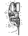
- FIG. 4 and 5 are cross-sectional views showing the internal structure of the hedge trimmer 10.
- FIG. 4 shows a state in which the main activation lever 46 is in the stop position, the front activation lever 26 is also in the stop position, and the lock operation member 50 is in the lock position. That is, the blade assembly 100 is not driven.
- FIG. 5 shows a state in which the main activation lever 46 is in the activation position, the front activation lever 26 is also in the activation position, and the lock operation member 50 is in the lock position. That is, the blade assembly 100 is driven.
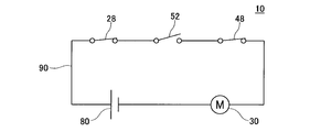
- 6 and 7 are circuit diagrams showing an electrical configuration of the hedge trimmer 10.
- FIG. 6 corresponds to FIG.
- FIG. 4 shows a state where the blade assembly 100 is not driven
- FIG. 7 corresponds to FIG. 5 and shows a state where the blade assembly 100 is driven.
- the portion related to the speed adjustment dial 54 is not shown.
- the first unit 20 includes a motor 30, a reduction gear 32 that amplifies the torque output from the motor 30, and rotational movement from the motor 30 for a pair of shear blades 102 and 104.
- a crank cam 34 for changing to a reciprocating motion is accommodated.
- the first unit 20 accommodates a front activation interlock switch 28 that is interlocked with the front activation lever 26.
- the motor 30 is connected to the battery pack 80 by the power supply circuit 90, and rotates upon receiving power supply from the battery pack 80.
- the front activation interlocking switch 28 is provided on the power supply circuit 90 and can turn on / off the power supply circuit 90.
- the front activation interlock switch 28 is turned off, and the power supply circuit 90 is shut off.
- the front activation lever 26 is operated to the activation position, the front activation interlock switch 28 is turned on and the power supply circuit 90 is turned on.
- the second unit 40 includes a main activation interlock switch 48 that is interlocked with the main activation lever 46, and a lock interlock switch 52 that is interlocked with the lock operation member 50 and the lock pin 60. Contained.
- the main activation interlock switch 48 is provided on the power supply circuit 90 and can turn on / off the power supply circuit 90. That is, when the main activation lever 46 is at the stop position, the main activation interlock switch 48 is turned off and the power supply circuit 90 is shut off. On the other hand, when the main activation lever 46 is operated to the activation position, the main activation interlock switch 48 is turned on and the power supply circuit 90 is turned on.
- the lock interlocking switch 52 is also provided on the power supply circuit 90, and the power supply circuit 90 can be turned on / off.
- the lock interlock switch 52 is turned on when the lock operation member 50 is in the lock position, and conducts the power supply circuit 90, and is turned off when the lock operation member 50 is operated to the unlock position. Circuit 90 is shut off. Therefore, as shown in FIG. 8, when the lock operating member 50 is operated to the unlock position and the lock interlock switch 52 is turned off, the motor 30 is driven even if the two start interlock switches 28 and 48 are turned on. It will never be done.
- the hedge trimmer 10 is configured such that the driving of the motor 30 is electrically prohibited when the lock between the first unit 20 and the second unit 40 is released.
- the second unit 40 is further provided with an interlock mechanism 64 that mechanically limits malfunction of the motor 30.
- the interlock mechanism 64 is mainly configured by a slider 66 interlocked with the lock operation member 50 and a hook 68 interlocked with the main activation lever 46.
- the interlock mechanism 64 can inhibit the lock operation member 50 from moving to the unlock position when the main activation lever 46 is in the activation position. Thereby, when the blade assembly 100 is driven for the motor 30, the lock by the lock pin 60 is released, and the second unit 40 can be prevented from rotating with respect to the first unit 20.
- the interlock mechanism 64 allows the main activation lever 46 to move from the stop position to the activation position even when the lock operation member 50 is in the unlock position, while the main activation lever 46 is in the activation position. In some cases, the lock operation member 50 can be prohibited from moving from the unlock position to the lock position.
- the interlock mechanism 64 of the present embodiment allows the main activation lever 46 to move from the stop position to the activation position even when the lock operation member 50 is in the unlock position. That is, if the user applies an operating force to the main activation lever 46, the main activation lever 46 is moved to the activation position. In addition, when the main activation lever 46 is operated to the activation position, the lock operation member 50 is prohibited from moving from the unlock position to the lock position. Accordingly, the lock operation member 50 is prohibited from being returned to the lock position while the main activation lever 46 is operated to the activation position, and the blade assembly 100 is prevented from being driven by the motor 30. When the lock operation member 50 is in the unlock position, the power supply circuit 90 is shut off by the lock interlock switch 52 (see FIG.
- the slider 66 of the interlock mechanism 64 is connected to the lock operation member 50 and is configured to move in the front-rear direction in accordance with the movement of the lock operation member 50 in the vertical direction. Specifically, when the lock operation member 50 moves upward toward the unlock position, the slider 66 moves rearward toward the main activation lever 46, and when the lock operation member 50 moves downward toward the lock position, the slider 66 moves forward away from the main activation lever 46. Further, the slider 66 is formed with an opening 66a extending in the vertical direction.
- the hook 68 of the interlock mechanism 64 is formed integrally with the main activation lever 46 and is configured to move in the vertical direction in response to the swing of the main activation lever 46. Specifically, when the main activation lever 46 moves upward toward the activation position, the hook 68 also moves upward, and when the main activation lever 46 moves downward toward the stop position, the hook 68 also moves downward.
- FIG. 3 shows a state in which the main activation lever 46 is operated to the activation position while the lock operation member 50 is operated to the unlock position.
- the hook 68 moves upward and enters the opening 66 a of the slider 66.
- the slider 66 is in a state in which the hook 68 is hooked, and is prohibited from moving forward.
- the lock operation member 50 connected to the slider 66 is also prohibited from moving downward toward the lock position.
- the lock operation member 50 is prohibited from being operated from the unlock position to the lock position.
- the above-described interlock mechanism 64 is an example, and its structure can be changed as necessary.
- the slider 66 may be interlocked with the main activation lever 46 and the hook 68 may be interlocked with the lock operation member 50.
- the combination of the slider 66 having the opening 66a and the hook 68 is a specific example of a pair of structures that can be engaged with each other, and another pair of structures that can be engaged can also be adopted.
- the interlock mechanism 64 only needs to be able to engage at least the lock operation member 50 in the unlock position and the main activation lever 46 (or the front activation lever 26) in the activation position.
- the embodiment described above is a hedge trimmer 10 used for trimming hedges, and in particular, a cordless hedge trimmer 10 using a battery as a power source.
- Japanese Patent Laid-Open No. 2007-275063 discloses a conventional cordless hedge trimmer.
- the hedge trimmer includes a pair of shear blades, a main body that drives at least one shear blade by a motor, and a battery that supplies electric power to the motor.
- the weight of the battery accounts for a large proportion of the total weight. Therefore, depending on the position where the battery is placed, the position of the center of gravity of the hedge trimmer changes greatly, and if the position where the battery is placed is inappropriate, the weight balance of the hedge trimmer will deteriorate, making it difficult for the user to use it. turn into.
- the user moves the shear blade along the surface of the hedge when cutting the hedge with the hedge trimmer.
- the posture (orientation) of the hedge trimmer is changed according to the orientation of the surface of the hedge. For example, when trimming the upper surface of the hedge, the user uses the hedge trimmer in a normal posture, and when trimming the side of the hedge, the user uses the hedge trimmer in a posture where the hedge trimmer is tilted sideways.
- This embodiment solves the above problem and provides a technique that allows a user to easily handle a hedge trimmer without strongly feeling the weight of the battery even when the attitude of the hedge trimmer is changed.
- the hedge trimmer 10 of this embodiment includes a pair of shear blades 102 and 104, a main body 12 that drives at least one of the shear blades 102 and 104 by the motor 30, and a battery 80 that supplies electric power to the motor 30.
- the main body 12 includes a first unit 20 and a second unit 40 that can rotate with respect to the first unit 20.
- a pair of shear blades 102 and 104 are attached to the first unit 20, and a battery 80 is attached to the second unit 40.
- Rotating the first unit 20 with respect to the second unit 40 can change the orientation of the pair of shear blades 102 and 104 while maintaining the position of the battery 80. Even when the orientation of the pair of shear blades 102 and 104 is changed according to the surface (for example, the upper surface or the side surface) that the hedge is trimmed, the position of the battery 80 can be prevented from changing greatly. The user can easily handle the hedge trimmer 10 without feeling the weight of the battery 80 strongly.
- the second unit 40 is provided with a handle 44 held by the user. According to this configuration, even when the second unit 40 is rotated with respect to the first unit 20, the positional relationship between the handle 44 and the battery 80 does not change. Thereby, even when the rotation position of the second unit is variously adjusted with respect to the first unit, the user does not feel the weight of the battery strongly, and can easily handle the hedge trimmer.
- a pair of shear blades 102, 104 extends forward from the first unit 20, and the weight of the pair of shear blades 102, 104 is offset in front of the hedge trimmer 10.
- a relatively heavy battery pack 80 is attached to the second unit 40 located behind the first unit 20, and the weight of the battery pack 80 is offset forward. According to this configuration, the weight of the pair of shear blades 102 and 104 and the weight of the battery pack 80 balance each other, and the weight distribution in the front-rear direction of the hedge trimmer is improved.
- the hedge trimmer 10 has been described in detail as an example.
- the technique disclosed in the present specification in particular, the technique for preventing the malfunction of the hedge trimmer 10 is not limited to this type of power tool, and is used outdoors. Other horticultural power tools used, or other types of power tools can be similarly implemented.
Landscapes
- Life Sciences & Earth Sciences (AREA)
- Biodiversity & Conservation Biology (AREA)
- Ecology (AREA)
- Forests & Forestry (AREA)
- Environmental Sciences (AREA)
- Engineering & Computer Science (AREA)
- Mechanical Engineering (AREA)
- Harvester Elements (AREA)
- Portable Power Tools In General (AREA)
Priority Applications (4)
| Application Number | Priority Date | Filing Date | Title |
|---|---|---|---|
| EP11747196.1A EP2540153B1 (de) | 2010-02-25 | 2011-02-10 | Elektrowerkzeug |
| US13/580,270 US9308637B2 (en) | 2010-02-25 | 2011-02-10 | Power tool |
| CN201180011176.1A CN102781222B (zh) | 2010-02-25 | 2011-02-10 | 动力工具 |
| RU2012140745/13A RU2522527C2 (ru) | 2010-02-25 | 2011-02-10 | Приводной инструмент |
Applications Claiming Priority (4)
| Application Number | Priority Date | Filing Date | Title |
|---|---|---|---|
| JP2010-039734 | 2010-02-25 | ||
| JP2010-039733 | 2010-02-25 | ||
| JP2010039734A JP5443208B2 (ja) | 2010-02-25 | 2010-02-25 | 動力工具 |
| JP2010039733A JP5342472B2 (ja) | 2010-02-25 | 2010-02-25 | ヘッジトリマ |
Publications (1)
| Publication Number | Publication Date |
|---|---|
| WO2011105232A1 true WO2011105232A1 (ja) | 2011-09-01 |
Family
ID=44506646
Family Applications (1)
| Application Number | Title | Priority Date | Filing Date |
|---|---|---|---|
| PCT/JP2011/052939 WO2011105232A1 (ja) | 2010-02-25 | 2011-02-10 | 動力工具 |
Country Status (5)
| Country | Link |
|---|---|
| US (1) | US9308637B2 (de) |
| EP (1) | EP2540153B1 (de) |
| CN (1) | CN102781222B (de) |
| RU (1) | RU2522527C2 (de) |
| WO (1) | WO2011105232A1 (de) |
Cited By (8)
| Publication number | Priority date | Publication date | Assignee | Title |
|---|---|---|---|---|
| CN102668895A (zh) * | 2012-06-05 | 2012-09-19 | 宁波伊司达工具有限公司 | 多功能修枝机 |
| CN103004485A (zh) * | 2011-09-21 | 2013-04-03 | 苏州宝时得电动工具有限公司 | 修枝剪和花园工具 |
| US20140047719A1 (en) * | 2012-08-20 | 2014-02-20 | Hitachi Koki Co., Ltd. | Hedge trimmer |
| CN103659752A (zh) * | 2012-09-26 | 2014-03-26 | 株式会社牧田 | 动力工具 |
| JP2017056555A (ja) * | 2016-11-09 | 2017-03-23 | 株式会社マキタ | 手持ち式電動工具 |
| US10155304B2 (en) | 2013-02-01 | 2018-12-18 | Makita Corporation | Electric tool |
| US11140833B2 (en) | 2018-02-05 | 2021-10-12 | Makita Corporation | Electric power tool |
| WO2022070763A1 (ja) * | 2020-09-30 | 2022-04-07 | 工機ホールディングス株式会社 | 作業機 |
Families Citing this family (28)
| Publication number | Priority date | Publication date | Assignee | Title |
|---|---|---|---|---|
| JP5530186B2 (ja) * | 2010-01-04 | 2014-06-25 | 株式会社マキタ | 手持式電動工具 |
| CN102802879B (zh) * | 2010-03-06 | 2016-05-25 | 胡斯华纳有限公司 | 电池组驱动的电力工具 |
| JP6032400B2 (ja) * | 2012-08-15 | 2016-11-30 | 日立工機株式会社 | チェーンソー |
| US9888627B2 (en) | 2012-10-15 | 2018-02-13 | Chervon (Hk) Limited | Lawncare apparatus with a foldable operating arm |
| US11606900B2 (en) | 2012-10-15 | 2023-03-21 | Chervon (Hk) Limited | Gardening tool |
| US9596806B2 (en) | 2013-10-10 | 2017-03-21 | Chervon (Hk) Limited | Control system for controlling the operation of a gardening tool |
| US20150328764A1 (en) | 2013-02-01 | 2015-11-19 | Makita Corporation | Power tool |
| US10131042B2 (en) | 2013-10-21 | 2018-11-20 | Milwaukee Electric Tool Corporation | Adapter for power tool devices |
| JP6277042B2 (ja) * | 2014-04-01 | 2018-02-07 | 株式会社マキタ | 電動工具 |
| JP6345523B2 (ja) * | 2014-07-23 | 2018-06-20 | 株式会社やまびこ | バッテリ駆動式作業機 |
| CN104704987A (zh) * | 2015-02-12 | 2015-06-17 | 侯巧生 | 电动剪切吹风式采茶机 |
| US9877435B2 (en) | 2015-09-15 | 2018-01-30 | Chervon (Hk) Limited | Hedge trimmer |
| EP3181306A1 (de) * | 2015-12-17 | 2017-06-21 | HILTI Aktiengesellschaft | Akkubetriebene handwerkzeugmaschine iii |
| CN105532276B (zh) * | 2016-01-18 | 2018-05-15 | 浙江亚特电器有限公司 | 一种多功能修枝剪草机 |
| USD875497S1 (en) * | 2017-12-12 | 2020-02-18 | Black & Decker, Inc. | Chain saw |
| JP2019134693A (ja) * | 2018-02-05 | 2019-08-15 | 株式会社マキタ | ヘッジトリマ |
| JP7049946B2 (ja) | 2018-06-28 | 2022-04-07 | 株式会社マキタ | ベルトサンダ |
| JP7228479B2 (ja) * | 2019-06-20 | 2023-02-24 | 株式会社やまびこ | 電動作業機 |
| CN112238422B (zh) * | 2019-07-16 | 2022-08-02 | 南京泉峰科技有限公司 | 手推式动力工具 |
| JP7337938B2 (ja) | 2019-09-06 | 2023-09-04 | 株式会社マキタ | 電動工具 |
| DE102020005909A1 (de) * | 2019-10-07 | 2021-04-08 | Makita Corporation | Heckenschere |
| US11285593B2 (en) * | 2020-05-05 | 2022-03-29 | Apex Mfg. Co., Ltd. | Electric stapler |
| WO2022051468A1 (en) | 2020-09-04 | 2022-03-10 | Milwaukee Electric Tool Corporation | Chainsaw |
| JP2022053268A (ja) * | 2020-09-24 | 2022-04-05 | 株式会社やまびこ | ヘッジトリマー |
| USD1037802S1 (en) * | 2021-06-09 | 2024-08-06 | Jiangsu Dongcheng Tools Technology Co., Ltd. | Pruning machine |
| DE102021211952A1 (de) * | 2021-10-22 | 2023-04-27 | Robert Bosch Gesellschaft mit beschränkter Haftung | Gehäusevorrichtung für eine Handwerkzeugmaschine und Handwerkzeugmaschine mit der Gehäusevorrichtung |
| CN114223419A (zh) * | 2021-11-30 | 2022-03-25 | 江苏东成工具科技有限公司 | 绿篱机 |
| US20230286130A1 (en) * | 2022-01-28 | 2023-09-14 | Nanjing Chervon Industry Co., Ltd. | Power tool |
Citations (8)
| Publication number | Priority date | Publication date | Assignee | Title |
|---|---|---|---|---|
| JPS4941138A (de) * | 1972-07-03 | 1974-04-17 | ||
| JPH03117573A (ja) | 1989-09-08 | 1991-05-20 | Stihl Andreas | 手で案内される作業機械 |
| US5150523A (en) * | 1991-07-11 | 1992-09-29 | Ryobi Motor Products Corporation | Deadman switch arrangement for a hedge trimmer |
| DE19532299A1 (de) | 1995-09-01 | 1997-03-06 | Viking Umwelttechnik | Handgeführtes Arbeitsgerät |
| JP2002171833A (ja) * | 2000-12-06 | 2002-06-18 | Makita Corp | ヘッジトリマ |
| JP2005160306A (ja) * | 2003-11-28 | 2005-06-23 | Honda Motor Co Ltd | 動力作業機 |
| JP2006101798A (ja) * | 2004-10-07 | 2006-04-20 | Makita Corp | 刈り込み機 |
| JP2007275063A (ja) | 2006-04-10 | 2007-10-25 | Andreas Stihl Ag & Co Kg | ヘッジトリマ |
Family Cites Families (7)
| Publication number | Priority date | Publication date | Assignee | Title |
|---|---|---|---|---|
| TWI326579B (en) * | 2003-11-28 | 2010-07-01 | Honda Motor Co Ltd | Power working machine |
| JP4615850B2 (ja) * | 2003-11-28 | 2011-01-19 | 本田技研工業株式会社 | 動力作業機 |
| CN101553346B (zh) * | 2006-09-05 | 2011-01-12 | 盛生投资有限公司 | 手持动力工具 |
| JP4946929B2 (ja) * | 2008-03-17 | 2012-06-06 | 日立工機株式会社 | 刈込機 |
| EP2196084A3 (de) * | 2008-12-11 | 2010-11-10 | Hitachi Koki CO., LTD. | Tragbares motorbetriebenes Werkzeug |
| US8833485B2 (en) * | 2009-04-08 | 2014-09-16 | Husqvarna Ab | Battery-powered portable tools |
| US8156656B2 (en) * | 2009-05-07 | 2012-04-17 | Black & Decker Inc. | Hedgetrimmer with rotatable rear handle |
-
2011
- 2011-02-10 RU RU2012140745/13A patent/RU2522527C2/ru active
- 2011-02-10 CN CN201180011176.1A patent/CN102781222B/zh active Active
- 2011-02-10 US US13/580,270 patent/US9308637B2/en active Active
- 2011-02-10 WO PCT/JP2011/052939 patent/WO2011105232A1/ja active Application Filing
- 2011-02-10 EP EP11747196.1A patent/EP2540153B1/de active Active
Patent Citations (8)
| Publication number | Priority date | Publication date | Assignee | Title |
|---|---|---|---|---|
| JPS4941138A (de) * | 1972-07-03 | 1974-04-17 | ||
| JPH03117573A (ja) | 1989-09-08 | 1991-05-20 | Stihl Andreas | 手で案内される作業機械 |
| US5150523A (en) * | 1991-07-11 | 1992-09-29 | Ryobi Motor Products Corporation | Deadman switch arrangement for a hedge trimmer |
| DE19532299A1 (de) | 1995-09-01 | 1997-03-06 | Viking Umwelttechnik | Handgeführtes Arbeitsgerät |
| JP2002171833A (ja) * | 2000-12-06 | 2002-06-18 | Makita Corp | ヘッジトリマ |
| JP2005160306A (ja) * | 2003-11-28 | 2005-06-23 | Honda Motor Co Ltd | 動力作業機 |
| JP2006101798A (ja) * | 2004-10-07 | 2006-04-20 | Makita Corp | 刈り込み機 |
| JP2007275063A (ja) | 2006-04-10 | 2007-10-25 | Andreas Stihl Ag & Co Kg | ヘッジトリマ |
Non-Patent Citations (1)
| Title |
|---|
| See also references of EP2540153A4 * |
Cited By (12)
| Publication number | Priority date | Publication date | Assignee | Title |
|---|---|---|---|---|
| CN103004485A (zh) * | 2011-09-21 | 2013-04-03 | 苏州宝时得电动工具有限公司 | 修枝剪和花园工具 |
| CN103004485B (zh) * | 2011-09-21 | 2015-03-11 | 苏州宝时得电动工具有限公司 | 修枝剪和花园工具 |
| CN102668895A (zh) * | 2012-06-05 | 2012-09-19 | 宁波伊司达工具有限公司 | 多功能修枝机 |
| US20140047719A1 (en) * | 2012-08-20 | 2014-02-20 | Hitachi Koki Co., Ltd. | Hedge trimmer |
| CN103659752A (zh) * | 2012-09-26 | 2014-03-26 | 株式会社牧田 | 动力工具 |
| CN103659752B (zh) * | 2012-09-26 | 2017-03-01 | 株式会社牧田 | 动力工具 |
| US10155304B2 (en) | 2013-02-01 | 2018-12-18 | Makita Corporation | Electric tool |
| US10994404B2 (en) | 2013-02-01 | 2021-05-04 | Makita Corporation | Electric tool |
| JP2017056555A (ja) * | 2016-11-09 | 2017-03-23 | 株式会社マキタ | 手持ち式電動工具 |
| US11140833B2 (en) | 2018-02-05 | 2021-10-12 | Makita Corporation | Electric power tool |
| WO2022070763A1 (ja) * | 2020-09-30 | 2022-04-07 | 工機ホールディングス株式会社 | 作業機 |
| JP7464139B2 (ja) | 2020-09-30 | 2024-04-09 | 工機ホールディングス株式会社 | 作業機 |
Also Published As
| Publication number | Publication date |
|---|---|
| EP2540153A1 (de) | 2013-01-02 |
| RU2522527C2 (ru) | 2014-07-20 |
| EP2540153B1 (de) | 2016-08-17 |
| EP2540153A4 (de) | 2015-02-25 |
| US20120317821A1 (en) | 2012-12-20 |
| US9308637B2 (en) | 2016-04-12 |
| RU2012140745A (ru) | 2014-03-27 |
| CN102781222A (zh) | 2012-11-14 |
| CN102781222B (zh) | 2014-04-16 |
Similar Documents
| Publication | Publication Date | Title |
|---|---|---|
| WO2011105232A1 (ja) | 動力工具 | |
| JP4983663B2 (ja) | 刈払機の操作ハンドル及び刈払機 | |
| US10710257B2 (en) | Power tool, such as a metal shears | |
| EP2606717B1 (de) | Vorrichtung zum Schneiden von Vegetation | |
| JP5342472B2 (ja) | ヘッジトリマ | |
| US20110308095A1 (en) | Portable cutting machine | |
| US10375896B2 (en) | Pole hedge trimmer | |
| JP4804823B2 (ja) | 携帯丸鋸 | |
| GB2464616A (en) | Power tool with rotatable working head | |
| JP5443208B2 (ja) | 動力工具 | |
| US11140833B2 (en) | Electric power tool | |
| CN104641960A (zh) | 修枝机 | |
| JP5068219B2 (ja) | 動力作業機 | |
| JP4615850B2 (ja) | 動力作業機 | |
| US9078395B2 (en) | Folding arrangement for a handle assembly of a walk-behind power tool | |
| CN114223419A (zh) | 绿篱机 | |
| JP2010172328A (ja) | 動力作業機 | |
| JP2023125623A (ja) | 草刈り機 | |
| EP3082396A1 (de) | Griffanordnung für ein elektrowerkzeug |
Legal Events
| Date | Code | Title | Description |
|---|---|---|---|
| WWE | Wipo information: entry into national phase |
Ref document number: 201180011176.1 Country of ref document: CN |
|
| 121 | Ep: the epo has been informed by wipo that ep was designated in this application |
Ref document number: 11747196 Country of ref document: EP Kind code of ref document: A1 |
|
| WWE | Wipo information: entry into national phase |
Ref document number: 13580270 Country of ref document: US |
|
| NENP | Non-entry into the national phase |
Ref country code: DE |
|
| REEP | Request for entry into the european phase |
Ref document number: 2011747196 Country of ref document: EP |
|
| WWE | Wipo information: entry into national phase |
Ref document number: 2011747196 Country of ref document: EP |
|
| WWE | Wipo information: entry into national phase |
Ref document number: 2012140745 Country of ref document: RU |