WO2011105187A1 - プレート体、同プレート体を備える摩擦クラッチ装置およびブレーキ装置 - Google Patents
プレート体、同プレート体を備える摩擦クラッチ装置およびブレーキ装置 Download PDFInfo
- Publication number
- WO2011105187A1 WO2011105187A1 PCT/JP2011/052255 JP2011052255W WO2011105187A1 WO 2011105187 A1 WO2011105187 A1 WO 2011105187A1 JP 2011052255 W JP2011052255 W JP 2011052255W WO 2011105187 A1 WO2011105187 A1 WO 2011105187A1
- Authority
- WO
- WIPO (PCT)
- Prior art keywords
- plate
- peripheral surface
- clutch
- pressed
- pressing
- Prior art date
- Legal status (The legal status is an assumption and is not a legal conclusion. Google has not performed a legal analysis and makes no representation as to the accuracy of the status listed.)
- Ceased
Links
Images

Classifications
-
- F—MECHANICAL ENGINEERING; LIGHTING; HEATING; WEAPONS; BLASTING
- F16—ENGINEERING ELEMENTS AND UNITS; GENERAL MEASURES FOR PRODUCING AND MAINTAINING EFFECTIVE FUNCTIONING OF MACHINES OR INSTALLATIONS; THERMAL INSULATION IN GENERAL
- F16D—COUPLINGS FOR TRANSMITTING ROTATION; CLUTCHES; BRAKES
- F16D13/00—Friction clutches
- F16D13/58—Details
- F16D13/60—Clutching elements
- F16D13/64—Clutch-plates; Clutch-lamellae
- F16D13/648—Clutch-plates; Clutch-lamellae for clutches with multiple lamellae
-
- F—MECHANICAL ENGINEERING; LIGHTING; HEATING; WEAPONS; BLASTING
- F16—ENGINEERING ELEMENTS AND UNITS; GENERAL MEASURES FOR PRODUCING AND MAINTAINING EFFECTIVE FUNCTIONING OF MACHINES OR INSTALLATIONS; THERMAL INSULATION IN GENERAL
- F16D—COUPLINGS FOR TRANSMITTING ROTATION; CLUTCHES; BRAKES
- F16D55/00—Brakes with substantially-radial braking surfaces pressed together in axial direction, e.g. disc brakes
- F16D55/24—Brakes with substantially-radial braking surfaces pressed together in axial direction, e.g. disc brakes with a plurality of axially-movable discs, lamellae, or pads, pressed from one side towards an axially-located member
-
- F—MECHANICAL ENGINEERING; LIGHTING; HEATING; WEAPONS; BLASTING
- F16—ENGINEERING ELEMENTS AND UNITS; GENERAL MEASURES FOR PRODUCING AND MAINTAINING EFFECTIVE FUNCTIONING OF MACHINES OR INSTALLATIONS; THERMAL INSULATION IN GENERAL
- F16D—COUPLINGS FOR TRANSMITTING ROTATION; CLUTCHES; BRAKES
- F16D65/00—Parts or details
- F16D65/02—Braking members; Mounting thereof
- F16D65/12—Discs; Drums for disc brakes
-
- F—MECHANICAL ENGINEERING; LIGHTING; HEATING; WEAPONS; BLASTING
- F16—ENGINEERING ELEMENTS AND UNITS; GENERAL MEASURES FOR PRODUCING AND MAINTAINING EFFECTIVE FUNCTIONING OF MACHINES OR INSTALLATIONS; THERMAL INSULATION IN GENERAL
- F16D—COUPLINGS FOR TRANSMITTING ROTATION; CLUTCHES; BRAKES
- F16D65/00—Parts or details
- F16D65/02—Braking members; Mounting thereof
- F16D2065/13—Parts or details of discs or drums
- F16D2065/134—Connection
- F16D2065/1356—Connection interlocking
- F16D2065/1368—Connection interlocking with relative movement both radially and axially
-
- F—MECHANICAL ENGINEERING; LIGHTING; HEATING; WEAPONS; BLASTING
- F16—ENGINEERING ELEMENTS AND UNITS; GENERAL MEASURES FOR PRODUCING AND MAINTAINING EFFECTIVE FUNCTIONING OF MACHINES OR INSTALLATIONS; THERMAL INSULATION IN GENERAL
- F16D—COUPLINGS FOR TRANSMITTING ROTATION; CLUTCHES; BRAKES
- F16D69/00—Friction linings; Attachment thereof; Selection of coacting friction substances or surfaces
- F16D2069/004—Profiled friction surfaces, e.g. grooves, dimples
Definitions
- the present invention relates to a friction clutch device that is disposed between a prime mover and a driven body that is rotationally driven by the prime mover, and that transmits or interrupts the driving force of the prime mover to the driven body, and a brake device that brakes rotational motion by the prime mover.
- a flat plate ring-shaped pressed member while relatively rotating in a state of being engaged with and supported by a concave or convex holding body side fitting portion formed on an inner peripheral surface or an outer peripheral surface of a cylindrical or shaft-shaped holding body BACKGROUND OF THE INVENTION 1.
- the present invention relates to a flat plate-like plate body that is pressed against or separated from a body, a friction clutch device including the plate body, and a brake device.
- a friction clutch device that is disposed between a prime mover and a driven body that is rotationally driven by the prime mover, and transmits or cuts the driving force of the prime mover to the driven body and a brake device that brakes the rotational motion by the prime mover, By pressing the flat plate-shaped plate body against the flat plate-shaped pressed body that is rotationally driven, the rotational driving force is transmitted to the pressed body or the rotational movement of the pressed body is braked.
- a plate body in such a friction clutch device or a brake device has, for example, a plurality of teeth radially on the outer peripheral surface of a ring-shaped pressing body that is pressed against the clutch friction plate as in the clutch plate shown in Patent Document 1 below. It is formed to project.
- the plate body rotates integrally with the outer case, with teeth formed on the outer peripheral surface meshing with a concave groove formed on the inner peripheral surface of the outer case housing the plate body.
- the plate body (clutch plate) as described above is engaged with the outer case through a predetermined gap, that is, a so-called play, displacement in the axial direction is allowed with respect to the outer case.
- the structure is also displaceable in the radial direction. For this reason, in a state where the plate body is separated from the clutch friction plate, the clutch plate may be displaced in the radial direction in the outer case due to the backlash, in particular, vertically downward due to its own weight.
- the gap between the outer peripheral surface of the plate body and the bottom surface of the outer case is narrowed in the lower side of the outer case, and in some cases, the outer peripheral surface of the plate body and the outer case The bottoms come into contact with each other and the gap in the same part is closed.
- the functional fluid medium for example, clutch oil
- the malfunction of the functional fluid medium means that the function expected of the functional fluid medium is not sufficiently exhibited.
- the cooling function of the plate body and the clutch friction plate and the plate For example, a function of removing dust intervening between the body and the clutch friction plate.
- the drag torque is the viscosity of the clutch oil existing between the clutch friction plate and the plate body due to the difference in the rotational speed between the clutch friction plate and the plate body when the clutch friction plate and the plate body are separated from each other. This torque is transmitted between the clutch friction plate and the plate body by the resistance, and contributes to the deterioration of fuel consumption of the vehicle.
- the present invention has been made to address the above problems, and its purpose is to provide a plate body and a plate body capable of maintaining the function of a functional fluid medium and reducing drag torque in a friction clutch device and a brake device. It is an object of the present invention to provide a friction clutch device and a brake device.
- the feature of the present invention according to claim 1 is that the concave or convex holding body side fitting portion formed on the inner peripheral surface or the outer peripheral surface of the cylindrical or axial holding body is engaged.
- a plate-like annular plate body that is relatively pressed against or separated from the plate-shaped annular pressed body while relatively rotating in a supported state, and is annularly pressed against and pressed against the pressed body.
- a flat plate-shaped pressing body having a pressing portion, and a pressing body provided with a convex or concave shape on the outer peripheral surface or inner peripheral surface of the pressing body facing the holding body side fitting portion of the holding body, and meshed with the holding body side fitting portion.
- a plate-side fitting portion that fits in a state, and a protruding portion that protrudes in a convex shape along the radial direction of the pressing body on the outer peripheral surface or inner peripheral surface of the pressing body facing the holding body-side fitting portion in the holding body It is in having.
- the plate body has a protruding protrusion formed on the outer peripheral surface or the inner peripheral surface of the pressing body formed in a flat plate shape. . For this reason, it is formed on the outer peripheral surface or inner peripheral surface of the plate body between the outer peripheral surface or inner peripheral surface of the plate body and the surface of the holding body facing each other in the friction clutch device or the wet brake device. There will be a convex protrusion. Thereby, when the plate body is separated from the pressed body, it is displaced in the radial direction, that is, even when the plate body is displaced toward a part of the holding body, the protruding portion causes the peripheral surface of the plate body and the holding body to be displaced.
- the friction clutch device using the present invention can reduce the drag torque by about 30% to 50% compared to the friction clutch device using the conventional plate body. It was confirmed.
- the projecting portion has a gap between the projecting portion and the surface of the retaining body facing the retaining body side fitting portion and the plate side fitting portion. That is, it is formed with a protruding amount that is less than the gap.
- the protrusion in the plate body is provided with a clearance (clearance) between the surface of the holding body facing the protrusion and provided in the holding body. It is formed with a protruding amount that is less than a clearance (clearance) between the holding body side fitting portion provided and the plate side fitting portion provided on the plate body. That is, the amount of displacement in the radial direction of the plate body conventionally corresponds to the amount of clearance (clearance) between the holding body side fitting portion provided on the holding body and the plate side fitting portion provided on the plate body. .
- the amount of protrusion of the protrusion formed on the plate body is set to an amount such that the gap with the surface of the holding body facing the protrusion is less than the gap between the holder-side fitting portion and the plate-side fitting portion.
- the displacement amount in the radial direction of the plate body can be made smaller than the conventional displacement amount.
- the gap between the holding body and the plate body can be further secured to ensure the fluidity of the functional fluid medium more accurately, and the function of the functional fluid medium can be maintained and drag torque can be further reduced. It can be done reliably.
- the plate body in the plate body, at least three protrusions are formed on an outer peripheral surface or an inner peripheral surface of the pressing body, and the pressing body is a pressed body. It is arranged in a friction clutch device that is pressed against and rotated together with the pressed body to transmit a rotational driving force via a holding body.
- the plate body includes at least three protrusions on the outer peripheral surface or the inner peripheral surface of the holding body.
- At least one protrusion is formed on the outer peripheral surface or the inner peripheral surface of the pressing body, and the pressing body is driven to rotate. It exists in arrange
- the plate body includes at least one protrusion on the outer peripheral surface or the inner peripheral surface of the holding body.
- the functional fluid medium in the brake device corresponds to air in the dry brake device and oil in the wet brake device. That is, as a brake device in the present invention, a dry brake device in which air is interposed between a plate body and a pressed body (for example, a rotating disk), and a wet type in which oil is interposed between the plate body and the pressed body. There is a brake device.
- the protrusion is formed on an outer peripheral surface or an inner peripheral surface adjacent to the plate-side fitting portion in the pressing body.
- the protrusion part is formed on the outer peripheral surface or inner peripheral surface adjacent to the plate side fitting part in a press body. Yes.
- the plate-side fitting portion formed on the peripheral surface of the pressing body in the plate body needs to be shaped with high accuracy in shape and position in order to be fitted to the holding body-side fitting portion of the holding body.
- the accuracy does not interfere with the inner peripheral surface or the outer peripheral surface of the holding portion. It only has to be molded. Therefore, it can form easily compared with the case where a protrusion part is provided on the plate side fitting part of the press body in a plate body.
- the present invention can be implemented not only as an invention of a plate body but also as an invention of a friction clutch device and a brake device provided with the plate body.
- the plate body is a flat plate having an annular pressing portion that is pressed against the pressed body and is in frictional contact.
- An annular pressing body and a plate that is provided in a convex or concave shape on the outer peripheral surface or inner peripheral surface of the pressing body facing the holding body side fitting portion of the holding body, and is fitted in a state of being engaged with the holding body side fitting portion Side fitting part,
- a pressed body that is formed in a flat plate shape and is driven to rotate, and a concave or convex shape formed on the inner or outer peripheral surface of a cylindrical or shaft-shaped holding body.
- a plate-like annular plate body that is pressed against or separated from the pressed body in a state of being rotatably supported by being engaged with the holding body side fitting portion of the plate, and the plate to be rotated and driven.
- the plate body is a flat plate annular pressing body having an annular pressing portion that is pressed against the pressed body and is in frictional contact, and a holding body
- a plate-side fitting portion that is provided in a convex shape or a concave shape on the outer peripheral surface or inner peripheral surface of the pressing body facing the holding body-side fitting portion, and fits in a state of being engaged with the holding body-side fitting portion, and the holding body
- the holding body side fitting part in The outer peripheral surface or inner peripheral surface of the pressing body toward, to be provided with a projection projecting in a convex shape along the radial direction of the pressing body.
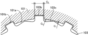
- FIG. 3 is a partially enlarged plan view showing a part of a clutch plate and an outer case shown in FIG. 2 in an enlarged manner.
- FIG. 3 is a partially enlarged plan view showing a part of a clutch plate and an outer case shown in FIG. 2 in an enlarged manner.
- FIG. 3 is a partially enlarged plan view showing a part of a clutch plate and an outer case shown in FIG. 2 in an enlarged manner.
- It is the graph which showed the drag torque in the friction clutch apparatus shown in FIG. 1 compared with the drag torque in the conventional friction clutch apparatus.
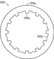
- It is a top view which shows the external appearance of the conventional clutch plate.
- It is a top view which shows the clutch plate which concerns on the modification of this invention.
- FIG. 1 is a cross-sectional view showing an overall configuration of a friction clutch device 100 including a clutch plate 103 as a clutch plate body according to the present invention.
- the friction clutch device 100 is a mechanical device for transmitting or blocking a driving force of an engine (not shown) as a prime mover in a two-wheeled motor vehicle (motorcycle) to a wheel (not shown) as a driven body. And a transmission (not shown).
- the friction clutch device 100 includes an outer case 101 made of an aluminum alloy.
- the outer case 101 is formed in a bottomed cylindrical shape, and is a component that constitutes a part of the housing of the friction clutch device 100.
- An input gear 102 is fixed to the left side surface of the outer case 101 by a rivet 102b via a torque damper 102a.
- the input gear 102 is rotationally driven in mesh with a drive gear (not shown) that is rotationally driven by driving of the engine.
- the inner peripheral surface 101a of the outer case 101 is formed with a fitting groove 101b for spline fitting and a plurality of sheets (eight in this embodiment) in a state of being engaged with the fitting groove 101b.
- a clutch plate 103 is provided.
- the fitting grooves 101b are grooves extending in a concave shape along the axial direction of the outer case 101, and a plurality of the fitting grooves 101b are formed along the circumferential direction of the inner peripheral surface 101a of the outer case 101.
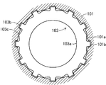
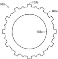
- the clutch plate 103 is a flat plate-shaped member that is pressed against a clutch friction plate 107, which will be described later, and is mainly composed of a pressing body 103a, a fitting convex portion 103b, and a protruding portion 103c.
- the pressing body 103a is a plate-like body pressed against the clutch friction plate 107, and is formed in a ring shape having a width corresponding to the radial width of the pressing portion of the clutch friction plate 107.
- the pressing portion of the ring-shaped region where the clutch friction plate is pressed on each side surface (front and back surfaces) of the pressing body 103a has a depth of several ⁇ m to several tens of ⁇ m for holding clutch oil, which will be described later, on the surface of the pressing portion.
- An oil groove (not shown) of ⁇ m is formed.
- both side surfaces (front and back surfaces) where the oil grooves in the pressing body 103a are formed are subjected to surface hardening treatment for the purpose of improving wear resistance.
- this surface hardening process is not directly related to this invention, the description is abbreviate
- the fitting protrusion 103b is a portion that fits into the fitting groove 101b of the outer case 101, and is formed to project radially from the outer peripheral surface of the pressing body 103a. That is, the fitting convex portion 103b is formed in a shape corresponding to the fitting groove 101b of the outer case 101 and smaller than the fitting portion 101a that has a clearance fitting relationship with the fitting groove 101b. ing.
- the fitting protrusions 103b are formed in the same number as the fitting grooves 101b, and in the present embodiment, twelve are formed on the outer peripheral surface of the pressing body 201 at equal intervals.
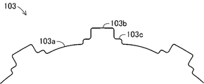
- the protruding portion 103c is formed to protrude radially from the outer peripheral surface adjacent to the fitting convex portion 103b in the pressing body 103a. More specifically, in the protrusion 103c, the outer peripheral surface of the pressing body 103a between the adjacent fitting protrusions 103b is outward from the two adjacent fitting protrusions 103b toward the center. It is formed in a substantially triangular shape that gradually protrudes. In the present embodiment, the tip of the protrusion 103c is formed in an arc shape of about 0.5R.
- the protrusion 103c is fitted the protrusion 103c is provided on the fitting groove 101b and the pressing member 103a of the gap (clearance) C 1 is provided on the outer case 101 and the inner circumferential surface 101a of the outer case 101 which faces the gap between the convex portion 103b is formed in the protruding amount less than (clearance) C 2.
- the clearance C 2 widths, length obtained by subtracting the width of the fitting projection 202 from the groove width of the fitting groove 101b (a direction perpendicular to the radial direction) of the groove 101b and the fitting protrusion 103b is there.
- the clearance (clearance) C 1 is set to 0.15 mm
- the clearance (clearance) C 2 is set to 0.25 mm.
- the clearances C 1 and C 2 are defined in the friction clutch device 100. It is set as appropriate according to the specifications.
- the clutch plate 103 is displaceable along the axial direction with respect to the outer case 101 by fitting the fitting convex portion 103b into the fitting groove 101b of the outer case 101 and meshing with each other. And is held in a rotatable state.
- the clutch plate 103 is formed by punching a thin plate material made of a SPCC (cold rolled steel plate) material in an annular shape. That is, the outer case 101 corresponds to the holding body according to the present invention, the fitting groove 101b corresponds to the holding body side fitting portion according to the present invention, and the fitting convex portion 103c corresponds to the plate side fitting portion according to the present invention. Equivalent to.
- a friction plate holder 104 formed in a substantially cylindrical shape is disposed concentrically with the outer case 101 inside the outer case 101.
- a large number of spline grooves are formed along the axial direction of the friction plate holder 104 on the inner peripheral surface of the friction plate holder 104, and the shaft 105 is spline-fitted with the spline grooves.
- the shaft 105 is a hollow shaft body, and one end (the right side in the drawing) is rotatably supported by the input gear 102 and the outer case 101 via the needle bearing 105a, and the friction that engages with the spline.
- the plate holder 104 is fixedly supported via the nut 105b. That is, the friction plate holder 104 rotates together with the shaft 105.
- the other end (left side in the figure) of the shaft 105 is connected to a transmission (not shown) in the two-wheeled vehicle.
- an axial push rod 106 is disposed so as to protrude from the one end (right side in the figure) of the shaft 105.
- the push rod 106 is connected to a clutch operating lever (not shown) of the two-wheeled vehicle on the opposite side (left side shown) of the shaft 105 protruding from one end (right side shown in the drawing).
- the inside of the hollow portion of the shaft 105 slides along the axial direction of the shaft 105.
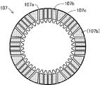
- a plurality of (seven in this embodiment) clutch friction plates 107 can be displaced along the axial direction of the friction plate holder 104 on the outer peripheral surface of the friction plate holder 104 with the clutch plate 103 interposed therebetween. And each is hold
- the clutch friction plate 107 includes a friction material 107b and an oil groove 107c on a flat plate-shaped cored bar 107a.
- the metal core 107a is a member that becomes a base portion of the clutch friction plate 107, and is formed by punching a thin plate material made of SPCC (cold rolled steel plate) material into a substantially annular shape.
- SPCC cold rolled steel plate
- an internal spline 107d for spline fitting with the friction plate holder 104 is formed on the inner peripheral surface of the metal core 107a.
- a plurality of small pieces of friction material 107b are provided on the side surface of the clutch friction plate 107 facing the clutch plate 103, that is, the side surface of the cored bar 107a facing the clutch plate 103. In the figure, the friction material 107b is hatched.
- the friction material 107b is a paper member for improving the frictional force against the clutch plate 103, and has two shapes of a rectangular shape and a triangular shape corresponding to the radial width of the annular portion of the cored bar 107a. Each is composed. These friction materials 107b are arranged with a predetermined gap from each other with respect to the core metal 107a, and are adhered by an adhesive (not shown). The gap between the friction materials 107b adjacent to each other is an oil groove 107c.
- the oil groove 107c is a groove functioning as an oil passage through which clutch oil, which will be described later, passes, and is formed with a depth corresponding to the thickness of the friction material 107b.
- the friction material 107b is made of a material that can improve the frictional force between the clutch friction plate 110 and the clutch plate 103, a material other than paper, such as a cork material, a rubber material, or a glass material, is used. Can also be used. That is, the clutch friction plate 107 corresponds to a pressed body according to the present invention.
- the friction plate holder 104 is filled with a predetermined amount of clutch oil (not shown) as a functional fluid medium, and three cylindrical support pillars 104a are formed (in the figure). Shows only one).
- the clutch oil is supplied between the clutch friction plate 107 and the clutch plate 103 to absorb friction heat generated between the clutch friction plate 107 and the clutch plate 103, prevent wear of the friction material 107b, and friction. Remove the generated dust. That is, the friction clutch device 100 is a so-called wet multi-plate friction clutch device.
- the three cylindrical support pillars 104a are formed so as to protrude outward in the axial direction (the right side in the drawing) of the friction plate holder 104, and are pressed covers arranged concentrically with the friction plate holder 104.
- 108 are assembled via bolts 109a, receiving plates 109b and coil springs 109c.
- the pressing cover 108 is formed in a substantially disc shape having an outer diameter substantially the same as the outer diameter of the clutch friction plate 107, and is pressed toward the friction plate holder 104 by the coil spring 109c.
- a release bearing 108 a is provided at the inner center portion of the pressing cover 108 at a position facing the right end portion of the push rod 106 in the figure.
- the tip of the push rod 106 does not press the release bearing 108a.
- the pressing cover 108 presses the clutch plate 103 by the elastic force of the coil spring 109c.
- the clutch plate 103 and the clutch friction plate 107 are rotationally driven together by being pressed against each other while being displaced toward the receiving portion 104b formed in a flange shape on the outer peripheral surface of the friction plate holder 104. To do.
- the driving force of the engine transmitted to the input gear 102 is transmitted to the transmission via the clutch plate 103, the clutch friction plate 110, the friction plate holder 104, and the shaft 105.
- the clutch oil filled in the friction clutch device 100 has a centrifugal force generated by the rotation of the clutch plate 103 and the clutch friction plate 110 by the clutch oil existing on the inner peripheral sides of the clutch plate 103 and the clutch friction plate 107. It moves toward each outer peripheral side of the clutch plate 103 and the clutch friction plate 110 according to the size. Thereby, clutch oil circulates in the friction clutch device 100.
- the radially displaceable amount of the clutch plate 103 is an amount corresponding to the gap C 1 between the distal end portion of the protruding portion 103 c of the clutch plate 103 and the inner peripheral surface 101 a of the outer case 101 at the maximum. .
- a gap C3 having a width corresponding to at least the protruding amount of the protruding portion 103c is formed on both sides of the protruding portion 103c.
- the fluidity of the clutch oil at the outer peripheral portions of the clutch plate 103 and the clutch friction plate 107 is ensured. This prevents the stagnation of the flow of the clutch oil due to the gap between the outer peripheral surface of the clutch plate 103 and the inner peripheral surface 101a of the outer case 101 being closed by the displacement of the clutch plate 103 in the radial direction. Therefore, it is possible to prevent malfunction (cooling function, dust removal function) of the clutch oil and increase in drag torque due to the stagnation of the flow of the clutch oil.
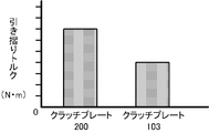
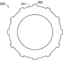
- FIG. 5 shows the magnitude of the drag torque in the friction clutch device 100 using the clutch plate 103 according to the present invention with respect to the drag torque in the friction clutch device (not shown) using the clutch plate 200 according to the prior art shown in FIG. It is a graph.
- the clutch plate 200 according to the related art includes a pressing body 201 and a fitting convex portion 202 corresponding to the pressing body 103a and the fitting convex portion 103b in the clutch plate 103 according to the present invention, respectively, as shown in FIG. It is prepared for. That is, the clutch plate 200 does not include the protruding portion 103c in the clutch plate 103 according to the present invention.
- the outer diameter of the pressing body 201 in the clutch plate 200 is substantially the same as the diameter of the circle connecting the vertices of the protrusions 103 c in the clutch plate 103.
- the friction clutch device according to the prior art has the same configuration as the friction clutch device 100 according to the present invention except for the clutch plate 100, and the rotational speeds of the clutch plate 103 and the clutch friction plate 107 are 1000 rpm.
- the friction clutch device 100 using the clutch plate 103 according to the present invention has a drag torque of about 30% compared to the friction clutch device using the clutch plate 200 according to the prior art. The reduction is realized. Further, according to an experiment by the present inventors, it was confirmed that the drag torque was reduced by about 50% when the same experiment was performed at a rotational speed of the clutch plate 103 and the clutch friction plate 107 at 3000 rpm.
- the clutch plate 103 has a convex protrusion 103c adjacent to the fitting protrusion 103b on the outer peripheral surface of the pressing body 103a formed in a flat plate ring shape. It has. For this reason, a convex protrusion formed on the outer peripheral surface of the clutch plate 103 is formed between the outer peripheral surface of the clutch plate 103 and the inner peripheral surface 101a of the outer case 101 facing each other in the friction clutch device 100.
- the part 103c exists.
- the shape of the protrusion 103c formed on the outer peripheral surface of the clutch plate 103 is a substantially triangular shape in plan view.
- the protruding portion 103c has a shape protruding from the outer peripheral surface of the clutch plate 103, as long as the shape can be formed a gap C 3 between the inner peripheral surface 101a of the outer case 101 that faces in the outer peripheral surface,
- the present invention is not limited to the above embodiment.
- the protruding portion 103c can be formed in a shape protruding in a semicircular shape from the outer peripheral surface of the pressing body 103a.
- the protrusion part 103c can also be formed in a step shape in the rising part of the fitting convex part 103b in the outer peripheral surface of the press body 103a.
- one protrusion 103c of the clutch plate 103 is formed between each of the fitting protrusions 103b adjacent to each other in the clutch plate 103 (pressing body 103a).
- the fluidity of the clutch oil at the formed portion can be ensured.
- a brake device that brakes the rotational motion of the pressed body by pressing a plate body (corresponding to the clutch plate 103) fixedly pressed against the pressed body (corresponding to the clutch friction plate 107) that rotates.
- one protrusion 103c is formed on the outer peripheral surface of the plate body, and the plate body is disposed in a state where the formed protrusion 103c is positioned on the bottom side in the holding portion.
- the functional fluid medium in the brake device corresponds to air in the dry brake device and oil in the wet brake device, respectively. That is, as a brake device in the present invention, a dry brake device in which air is interposed between a plate body and a pressed body (for example, a rotating disk), and a wet type in which oil is interposed between the plate body and the pressed body. There is a brake device.
- the protrusion 103c is at least on the outer peripheral surface of the clutch plate 103.
- Three or more may be formed.
- a substantially uniform gap C 3 is always ensured on the entire circumference of the clutch plate 103 between the outer peripheral surface of the clutch plate 103 and the inner peripheral surface 101a of the outer case 101 facing each other in the friction clutch device 100. Therefore, the fluidity of the clutch oil between the outer case 101 and the clutch plate 103 can be ensured with higher accuracy regardless of the rotation stop position of the outer case 101, and the drag torque can be reduced.
- two or more protrusions 103 c can be formed between the fitting protrusions 103 b adjacent to each other in the clutch plate 103.
- the protruding portion 103c is formed at an intermediate position between the adjacent fitting convex portions 103b on the outer peripheral surface of the pressing body 103a. This is because the fitting convex portion 103b meshes with the fitting groove 101b formed on the inner peripheral surface 101a of the outer case 101 through a predetermined fitting relationship, and therefore the fitting convex portion 103b. This is because it is necessary to increase the accuracy in the formation position and the accuracy in molding, and it is difficult to form the protruding portion 103c on the fitting convex portion 103b.
- the protrusion 103c is formed on the outer peripheral surface of the pressing body 103a, if the protrusion 103c is formed within a predetermined tolerance, the other forming accuracy and the formation position accuracy are relatively low. And can be easily formed.
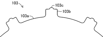
- the protrusion 103c according to the present invention is formed on the fitting protrusion 103b. That is, as shown in FIG. 9, the protruding portion 103c can be formed so as to protrude convexly outward in the radial direction on the fitting convex portion 103b formed on the outer peripheral surface of the pressing body 103a. Also by this, the same effect as the above-mentioned embodiment can be expected.
- the protruding portion 103 c of the clutch plate 103 is configured with a protruding amount that forms the gap C 1 with respect to the inner peripheral surface 101 a of the outer case 101.
- the protruding portion 103c of the clutch plate 103 is not limited to the above embodiment as long as it is a protruding amount that forms a gap C3 by protruding a part of the outer peripheral surface of the pressing body 103a. Therefore, the protrusion amount of the protrusion 103c in the clutch plate 103 may be less than the protrusion amount of the above embodiment, or may be equal to or more than the protrusion amount of the above embodiment.
- the protruding portion 103c of the clutch plate 103 can be formed with a protruding amount such that the tip of the protruding portion 103c is always in contact with the inner peripheral surface 101a of the outer case 101.
- the friction clutch device 100 holds the clutch plate 103 on the outer case 101 that is a driving-side rotating body through meshing engagement and a friction plate holder that is a driven-side rotating body.
- the clutch friction plate 107 is held by 104 through spline fitting.
- the clutch plate 103 does not necessarily need to be provided on the driving-side rotator, and may be provided on the driven-side rotator.
- the clutch friction plate 107 is held on the outer case 101 that is the driving side rotating body via the meshing engagement, and the clutch plate 103 is engaged on the friction plate holder 104 that is the driven side rotating body via the meshing engagement.
- the friction clutch device 100 can also be configured by holding them.
- the clutch plate 103 is configured by forming a fitting convex portion 103b and a protruding portion 103c on the inner peripheral surface of the pressing body 103a. That is, if the fitting convex part 103b and the protrusion part 103c are formed facing the surface side of the holding body that meshes with the clutch plate 103, the fitting convex part 103b and the protruding part 103c are not necessarily formed on the outer peripheral surface of the clutch plate 103. Absent.
- the protrusion 103c is provided on the outer peripheral surface of the clutch friction plate 107 that meshes and fits with the outer case 101 that is the driving-side rotating body, so that the clutch friction plate 107 in the outer case 101 is moved in the radial direction. Can also be prevented.
- the convex fitting convex part 103b was formed in the outer peripheral surface of the press body 103a.
- the fitting groove 101b and the fitting convex portion 103b are not necessarily limited to the above embodiment as long as the outer case 101 and the clutch plate 103 can be engaged with each other. That is, a convex fitting convex portion is formed on the inner peripheral surface 101 a of the outer case 101, and a concave fitting groove that fits and meshes with the fitting convex portion is provided on the outer peripheral surface of the clutch plate 103. It may be.
- the shape, size, and number of installations of the clutch plate 103 in the above embodiment are appropriately determined according to the specifications of the friction clutch device 100, and are naturally not limited to the above embodiment. .
- the plate body according to the present invention is in a state of being supported by meshing with a concave or convex holding body side fitting portion formed on the inner peripheral surface or the outer peripheral surface of the cylindrical or shaft-shaped holding body.
- the plate body according to the present invention can be widely implemented as a flat plate-like plate body that is relatively pressed against or separated from a flat plate-like pressed body while rotating relatively.
- the plate body according to the present invention can also be used as a plate body in the brake device described above.
Landscapes
- Engineering & Computer Science (AREA)
- General Engineering & Computer Science (AREA)
- Mechanical Engineering (AREA)
- Mechanical Operated Clutches (AREA)
- Braking Arrangements (AREA)
Priority Applications (4)
| Application Number | Priority Date | Filing Date | Title |
|---|---|---|---|
| DE112011100684T DE112011100684T5 (de) | 2010-02-25 | 2011-02-03 | Scheibenelement und mit Scheibenelement versehene Bremsvorrichtung |
| CA2790258A CA2790258A1 (en) | 2010-02-25 | 2011-02-03 | Plate element, and friction clutch device and brake device provided with plate element |
| CN2011800087989A CN102770677A (zh) | 2010-02-25 | 2011-02-03 | 板状组件、具有该板状组件的摩擦离合器装置及煞车装置 |
| US13/261,403 US8967340B2 (en) | 2010-02-25 | 2011-02-03 | Plate element, and friction clutch device and brake device provided with the plate element |
Applications Claiming Priority (2)
| Application Number | Priority Date | Filing Date | Title |
|---|---|---|---|
| JP2010-040958 | 2010-02-25 | ||
| JP2010040958A JP2011174597A (ja) | 2010-02-25 | 2010-02-25 | プレート体、同プレート体を備える摩擦クラッチ装置およびブレーキ装置 |
Publications (1)
| Publication Number | Publication Date |
|---|---|
| WO2011105187A1 true WO2011105187A1 (ja) | 2011-09-01 |
Family
ID=44506605
Family Applications (1)
| Application Number | Title | Priority Date | Filing Date |
|---|---|---|---|
| PCT/JP2011/052255 Ceased WO2011105187A1 (ja) | 2010-02-25 | 2011-02-03 | プレート体、同プレート体を備える摩擦クラッチ装置およびブレーキ装置 |
Country Status (6)
| Country | Link |
|---|---|
| US (1) | US8967340B2 (enExample) |
| JP (1) | JP2011174597A (enExample) |
| CN (1) | CN102770677A (enExample) |
| CA (1) | CA2790258A1 (enExample) |
| DE (1) | DE112011100684T5 (enExample) |
| WO (1) | WO2011105187A1 (enExample) |
Families Citing this family (7)
| Publication number | Priority date | Publication date | Assignee | Title |
|---|---|---|---|---|
| JP5499998B2 (ja) * | 2010-08-31 | 2014-05-21 | 日産自動車株式会社 | 駆動力伝達装置 |
| JP5972783B2 (ja) * | 2012-12-27 | 2016-08-17 | 株式会社エフ・シー・シー | 多板式クラッチ装置 |
| DE102013226393B4 (de) * | 2013-01-17 | 2020-06-25 | Schaeffler Technologies AG & Co. KG | Reibscheibe für eine Kupplungseinrichtung, Kupplungseinrichtung sowie Drehmomentübertragungseinrichtung |
| CN104895972B (zh) * | 2015-04-22 | 2017-07-25 | 安徽龙行密封件有限公司 | 一种离合器摩擦片组件 |
| JP6808571B2 (ja) * | 2017-04-14 | 2021-01-06 | 本田技研工業株式会社 | 摩擦係合装置の環状部材抜け止め構造 |
| JP6685069B1 (ja) * | 2018-11-28 | 2020-04-22 | 株式会社エフ・シー・シー | 湿式摩擦プレート、同湿式摩擦プレートを備えた湿式多板クラッチ装置および湿式摩擦プレートの製造方法 |
| JP7492321B2 (ja) * | 2019-10-01 | 2024-05-29 | 株式会社エフ・シー・シー | クラッチ装置 |
Citations (3)
| Publication number | Priority date | Publication date | Assignee | Title |
|---|---|---|---|---|
| JPH04125317A (ja) * | 1990-09-13 | 1992-04-24 | Nissan Motor Co Ltd | 湿式多板締結装置 |
| JP2006242295A (ja) * | 2005-03-03 | 2006-09-14 | Toyota Industries Corp | 差動制限装置 |
| JP2009138901A (ja) * | 2007-12-10 | 2009-06-25 | Aisin Chem Co Ltd | 自動変速機用トルク伝達機構 |
Family Cites Families (16)
| Publication number | Priority date | Publication date | Assignee | Title |
|---|---|---|---|---|
| US4762215A (en) * | 1981-11-06 | 1988-08-09 | Dana Corporation | Brake torque limiting coupling |
| JPH04107324A (ja) * | 1990-08-24 | 1992-04-08 | Nissan Motor Co Ltd | 湿式多板クラッチ |
| US5174420A (en) * | 1991-05-02 | 1992-12-29 | Clark Equipment Company | Wet disc brake |
| ES2088511T4 (es) * | 1992-02-01 | 2002-11-16 | Raybestos Ind Produkte Gmbh | Revestimiento de friccion o similar. |
| JP3245292B2 (ja) | 1994-02-25 | 2002-01-07 | 株式会社エクセディ | クラッチプレート |
| JPH0861386A (ja) * | 1994-08-18 | 1996-03-08 | Nsk Warner Kk | 湿式多板摩擦クラッチ及びその製造方法 |
| WO1996018050A1 (en) * | 1994-12-09 | 1996-06-13 | Means Industries, Inc. | Clutch plate |
| CA2165049C (en) * | 1994-12-21 | 2000-07-18 | Wayne M. Avers | Clutch plate for automatic transmissions |
| DE19514817A1 (de) * | 1995-04-21 | 1996-10-24 | Fichtel & Sachs Ag | Reibungskupplung für ein Kraftfahrzeug |
| JP2001527192A (ja) * | 1997-12-18 | 2001-12-25 | ルーク ラメレン ウント クツプルングスバウ ゲゼルシヤフト ミツト ベシユレンクテル ハフツング | クラッチディスク |
| US20040099371A1 (en) * | 2002-11-22 | 2004-05-27 | Hardies Tom C. | Multi-segmented friction plate with maximized steel-to-oil surface area for improved thermal capacity |
| US20050126878A1 (en) * | 2003-12-16 | 2005-06-16 | Farzad Samie | Segmented clutch plate for automatic transmission |
| EP1910704B1 (en) * | 2005-08-04 | 2012-01-25 | BorgWarner, Inc. | Friction plates and various methods of manufacture thereof |
| US20070062777A1 (en) * | 2005-09-22 | 2007-03-22 | Przemyslaw Zagrodzki | Friction plates and reaction plates for friction clutches and brakes with reduced thermal stresses |
| JP4125317B2 (ja) | 2005-12-12 | 2008-07-30 | 夏宗 陳 | 落下試験の計測方法及びその装置 |
| JP2009168144A (ja) * | 2008-01-16 | 2009-07-30 | Nissan Motor Co Ltd | スプライン構造及びこれを備える駆動力伝達装置 |
-
2010
- 2010-02-25 JP JP2010040958A patent/JP2011174597A/ja active Pending
-
2011
- 2011-02-03 CN CN2011800087989A patent/CN102770677A/zh active Pending
- 2011-02-03 CA CA2790258A patent/CA2790258A1/en not_active Abandoned
- 2011-02-03 WO PCT/JP2011/052255 patent/WO2011105187A1/ja not_active Ceased
- 2011-02-03 DE DE112011100684T patent/DE112011100684T5/de not_active Withdrawn
- 2011-02-03 US US13/261,403 patent/US8967340B2/en active Active
Patent Citations (3)
| Publication number | Priority date | Publication date | Assignee | Title |
|---|---|---|---|---|
| JPH04125317A (ja) * | 1990-09-13 | 1992-04-24 | Nissan Motor Co Ltd | 湿式多板締結装置 |
| JP2006242295A (ja) * | 2005-03-03 | 2006-09-14 | Toyota Industries Corp | 差動制限装置 |
| JP2009138901A (ja) * | 2007-12-10 | 2009-06-25 | Aisin Chem Co Ltd | 自動変速機用トルク伝達機構 |
Also Published As
| Publication number | Publication date |
|---|---|
| CN102770677A (zh) | 2012-11-07 |
| US20130015025A1 (en) | 2013-01-17 |
| CA2790258A1 (en) | 2011-09-01 |
| DE112011100684T5 (de) | 2013-03-14 |
| JP2011174597A (ja) | 2011-09-08 |
| US8967340B2 (en) | 2015-03-03 |
Similar Documents
| Publication | Publication Date | Title |
|---|---|---|
| JP5776310B2 (ja) | 湿式摩擦プレート | |
| WO2011105187A1 (ja) | プレート体、同プレート体を備える摩擦クラッチ装置およびブレーキ装置 | |
| US7966901B2 (en) | Torque transfer device | |
| JP5272089B1 (ja) | モータサイクル用クラッチ装置 | |
| US11215236B2 (en) | Clutch device | |
| WO2011074481A1 (ja) | 湿式多板摩擦クラッチ装置 | |
| JP2011174597A5 (enExample) | ||
| WO2024058174A1 (ja) | クラッチ装置および自動二輪車並びにプレッシャプレートの製造方法 | |
| WO2018235443A1 (ja) | 湿式摩擦プレート | |
| JP5500663B2 (ja) | 湿式多板摩擦クラッチ装置 | |
| JP2020090989A (ja) | 動力伝達装置 | |
| TW201837332A (zh) | 離合器摩擦片以及離合器裝置 | |
| JP7219673B2 (ja) | 湿式摩擦プレートおよび湿式多板クラッチ装置 | |
| US20240084857A1 (en) | Clutch device and motorcycle | |
| JP6117702B2 (ja) | マルチフリーディスク式クラッチ | |
| JP2024044961A (ja) | クラッチ装置 | |
| US11940013B1 (en) | Clutch device and motorcycle | |
| JP7581288B2 (ja) | クラッチ装置 | |
| US20250369487A1 (en) | Clutch device | |
| JP2018179303A (ja) | クラッチ摩擦板およびクラッチ装置 | |
| JP2025082451A (ja) | 差動制限装置 | |
| JP2024012030A (ja) | クラッチ装置および自動二輪車 |
Legal Events
| Date | Code | Title | Description |
|---|---|---|---|
| WWE | Wipo information: entry into national phase |
Ref document number: 201180008798.9 Country of ref document: CN |
|
| 121 | Ep: the epo has been informed by wipo that ep was designated in this application |
Ref document number: 11747151 Country of ref document: EP Kind code of ref document: A1 |
|
| ENP | Entry into the national phase |
Ref document number: 2790258 Country of ref document: CA |
|
| WWE | Wipo information: entry into national phase |
Ref document number: 13261403 Country of ref document: US |
|
| WWE | Wipo information: entry into national phase |
Ref document number: 7239/DELNP/2012 Country of ref document: IN |
|
| WWE | Wipo information: entry into national phase |
Ref document number: 112011100684 Country of ref document: DE Ref document number: 1120111006845 Country of ref document: DE |
|
| 122 | Ep: pct application non-entry in european phase |
Ref document number: 11747151 Country of ref document: EP Kind code of ref document: A1 |