WO2011104882A1 - 太陽光発電システム - Google Patents
太陽光発電システム Download PDFInfo
- Publication number
- WO2011104882A1 WO2011104882A1 PCT/JP2010/053164 JP2010053164W WO2011104882A1 WO 2011104882 A1 WO2011104882 A1 WO 2011104882A1 JP 2010053164 W JP2010053164 W JP 2010053164W WO 2011104882 A1 WO2011104882 A1 WO 2011104882A1
- Authority
- WO
- WIPO (PCT)
- Prior art keywords
- power
- solar cell
- cell array
- voltage
- power generation
- Prior art date
Links
Images


Classifications
-
- G—PHYSICS
- G05—CONTROLLING; REGULATING
- G05F—SYSTEMS FOR REGULATING ELECTRIC OR MAGNETIC VARIABLES
- G05F1/00—Automatic systems in which deviations of an electric quantity from one or more predetermined values are detected at the output of the system and fed back to a device within the system to restore the detected quantity to its predetermined value or values, i.e. retroactive systems
- G05F1/66—Regulating electric power
- G05F1/67—Regulating electric power to the maximum power available from a generator, e.g. from solar cell
-
- Y—GENERAL TAGGING OF NEW TECHNOLOGICAL DEVELOPMENTS; GENERAL TAGGING OF CROSS-SECTIONAL TECHNOLOGIES SPANNING OVER SEVERAL SECTIONS OF THE IPC; TECHNICAL SUBJECTS COVERED BY FORMER USPC CROSS-REFERENCE ART COLLECTIONS [XRACs] AND DIGESTS
- Y02—TECHNOLOGIES OR APPLICATIONS FOR MITIGATION OR ADAPTATION AGAINST CLIMATE CHANGE
- Y02E—REDUCTION OF GREENHOUSE GAS [GHG] EMISSIONS, RELATED TO ENERGY GENERATION, TRANSMISSION OR DISTRIBUTION
- Y02E10/00—Energy generation through renewable energy sources
- Y02E10/50—Photovoltaic [PV] energy
- Y02E10/56—Power conversion systems, e.g. maximum power point trackers
Definitions
- the output curve characteristics of the solar cell array (PV array) and the power generation conditions are controlled by, for example, a remote monitoring control device.
- the present invention relates to a photovoltaic power generation system that can be obtained synchronously.
- Patent Document 1 Japanese Patent Application Laid-Open No. 2006-201827 includes a power conditioner with a built-in curve tracer in order to determine an output abnormality of the photovoltaic power generation system with the photovoltaic power generation system installed in the field. It is disclosed.
- This curve tracer measures the DC current (I) corresponding to the DC voltage (V) of the solar cell, traces the DC current (I) -DC voltage (V) curve, and displays the trace result on the display. It is possible to determine whether the photovoltaic power generation system is normal or abnormal by viewing the display.
- strength and temperature which are the electric power generation conditions for evaluating the output of a solar power generation system are not traced, but it is from the solar cell reference conditions (1KW / m ⁇ 2 >, 25 degreeC). It was difficult to evaluate and compare with the estimated values.
- the present invention can display the output characteristics of the solar cell array and the power generation conditions of the solar cell array in synchronization.
- a solar power generation system characterized by providing a control device.
- the present invention provides a curve trace device that traces output characteristics of a direct current I and a direct current voltage V, which are at least outputs for each solar cell array, for each solar cell array.
- a control device capable of controlling display of each of the curve trace devices in synchronization is provided.
- FIG. 1 is a schematic configuration diagram for explaining a first embodiment of the photovoltaic power generation system of the present invention.
- FIG. 2 is a schematic configuration diagram for explaining a second embodiment of the photovoltaic power generation system of the present invention.
- FIG. 3 is a schematic configuration diagram for explaining a third embodiment of the photovoltaic power generation system of the present invention.
- FIG. 4 is a schematic configuration diagram for explaining a fourth embodiment of the photovoltaic power generation system of the present invention.
- FIG. 5 is a schematic configuration diagram for explaining a fifth embodiment of the photovoltaic power generation system of the present invention.
- FIG. 6 is a schematic configuration diagram for explaining a sixth embodiment of the photovoltaic power generation system of the present invention.
- FIG. 1 is a schematic configuration diagram for explaining a first embodiment of the photovoltaic power generation system of the present invention.
- FIG. 2 is a schematic configuration diagram for explaining a second embodiment of the photovoltaic power generation system of the present invention.
- FIG. 3 is a
- FIG. 7 is a schematic configuration diagram for explaining a seventh embodiment of the photovoltaic power generation system of the present invention.
- FIG. 8 is a schematic configuration diagram for explaining an eighth embodiment of the photovoltaic power generation system of the present invention.
- FIG. 9 is a schematic configuration diagram for explaining a ninth embodiment of the photovoltaic power generation system of the present invention.
- FIG. 10 is a schematic configuration diagram for explaining a tenth embodiment of the photovoltaic power generation system of the present invention.
- FIG. 11 is a schematic block diagram for demonstrating 11th Embodiment of the solar energy power generation system of this invention.
- FIG. 12 is a schematic configuration diagram for explaining a twelfth embodiment of the photovoltaic power generation system of the present invention.
- FIG. 13 is a schematic block diagram for demonstrating 13th Embodiment of the solar energy power generation system of this invention.
- FIG. 14 is a flowchart for explaining the operation of the first embodiment of the photovoltaic power generation system of the present invention.
- FIG. 15 is a flowchart for explaining the operation of the first embodiment of the photovoltaic power generation system of the present invention.
- FIG. 16 is an operation explanatory diagram for explaining the operation of each part of the first embodiment in the photovoltaic power generation system of the present invention.
- FIG. 17 is an operation explanatory diagram for explaining the operation of each part of the first embodiment in the photovoltaic power generation system of the present invention.
- FIG. 14 is a flowchart for explaining the operation of the first embodiment of the photovoltaic power generation system of the present invention.
- FIG. 15 is a flowchart for explaining the operation of the first embodiment of the photovoltaic power generation system of the present invention.
- FIG. 16 is an operation explanatory diagram for explaining the operation of each part
- FIG. 18 is an operation explanatory diagram for explaining the operation of each part of the first embodiment in the photovoltaic power generation system of the present invention.
- FIG. 19A is a diagram for explaining a display method of the display device for displaying the output of the curve tracing device in the photovoltaic power generation system of the present invention.
- FIG. 19B is a diagram for explaining a display method of the display device for displaying the output of the curve tracing device in the photovoltaic power generation system of the present invention.
- FIG. 19C is a diagram for explaining a display method of the display device that displays the output of the curve tracing device in the photovoltaic power generation system of the present invention.
- FIG. 19A is a diagram for explaining a display method of the display device for displaying the output of the curve tracing device in the photovoltaic power generation system of the present invention.
- FIG. 19B is a diagram for explaining a display method of the display device for displaying the output of the curve tracing device in the photovolt
- FIG. 20A is a diagram for explaining a display method of the display device that displays the output of the curve tracing device in the photovoltaic power generation system of the present invention.
- FIG. 20B is a diagram for explaining a display method of the display device for displaying the output of the curve tracing device in the photovoltaic power generation system of the present invention.
- FIG. 21 is a diagram for explaining a display method of the display device that displays the output of the curve tracing device in the photovoltaic power generation system of the present invention.
- FIG. 22A is a diagram for explaining a display method of the display device that displays the output of the curve tracing device in the photovoltaic power generation system of the present invention.
- FIG. 20B is a diagram for explaining a display method of the display device for displaying the output of the curve tracing device in the photovoltaic power generation system of the present invention.
- FIG. 21 is a diagram for explaining a display method of the display device that displays the output of the curve tracing device
- FIG. 22B is a diagram for explaining a display method of the display device that displays the output of the curve tracing device in the photovoltaic power generation system of the present invention.
- FIG. 22C is a diagram for explaining a display method of the display device for displaying the output of the curve tracing device in the photovoltaic power generation system of the present invention.
- FIG. 23A is a diagram for explaining a display method of the display device that displays the output of the curve tracing device in the photovoltaic power generation system of the present invention.
- FIG. 23B is a diagram for explaining a display method of the display device that displays the output of the curve tracing device in the photovoltaic power generation system of the present invention.
- FIG. 24 is a diagram for explaining a display method of the display device that displays the output of the curve tracing device in the photovoltaic power generation system of the present invention.
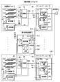
- FIG. 1 is a schematic configuration diagram for explaining a first embodiment of the present invention, which includes a plurality of groups of photovoltaic power generation systems 101...
- the DC power generated by the power generation battery systems 101... 10N is converted into AC power by the power conditioners 21... 2N and supplied to the commercial power source (AC power system) 5.
- the remote monitoring control device 1 monitors and controls the state of the photovoltaic power generation systems 101... 10N.
- the solar power generation system 101 includes a group of solar cell arrays 41, a power conditioner 21 that converts DC power generated by the solar cell array 41 into AC power and supplies the AC power to the AC power system 5, and a solar cell.
- a current collection box 81 and an electric circuit 71 disposed between the array 41 and the power conditioner 21, and a measuring device 31 that measures the power generation conditions of the solar cell array 41 are provided.
- the photovoltaic power generation system 10 ⁇ / b> N converts a group of solar cell arrays 4 ⁇ / b> N and DC power generated by the solar cell array 4 ⁇ / b> N into AC power and supplies the AC power to the AC power system 5.
- a power conditioner 2N, a current collection box 8N and an electric circuit 7N disposed between the solar cell array 4N and the power conditioner 2N, and a measuring device 3N for measuring power generation conditions of the solar cell array 4N are provided. .
- the solar cell array is a combination of a plurality of solar cells, which are the smallest unit of solar cells, to form a solar cell module (solar cell panel).
- This solar cell array is referred to as one group or a single unit, and a plurality of solar cell arrays are referred to as a plurality of groups or a plurality of units.
- Communication devices 12, 212 ... 2N2, 313 ... 3N3 are installed in the remote monitoring control device 1 and the power conditioners 21 ... 2N and the measurement devices 31 ... 3N of the respective groups, respectively, and the communication devices 12 of the remote monitoring control device 1 are measured.
- Signal transmission paths 911 that enable communication between the devices 31... 3N communication devices 313... 3N3 and between the communication devices 12 of the remote monitoring control device 1 and the power conditioners 21. 9N1, 912... 9N2, 913... 9N3.
- the power conditioner 21 detects a DC voltage that is an input of the power conversion device 211, the control switching device 213, the communication device 212, and the power conversion device 211 and an output of the solar cell array 41.
- a DC voltage detector 214 that supplies a voltage detection value Vdc to the control switching device 213 and the communication device 212 and a DC current that is an input of the power conversion device 211 and an output of the solar cell array 41 are detected.
- a DC current detector 215 that supplies a current detection value Idc to the control switching device 213 and the communication device 212.
- the control switching device 213 receives the DC voltage command Vref or the DC current command Iref and the control switching command SCAN from the remote monitoring control device 1 via the communication system, and the power conditioner 21 has power. Switching from MPPT (Max Power Point Tracking) control that controls the output of the converter 211 to a maximum is switched to voltage control or current control by the DC voltage command Vref or DC current command Iref.
- MPPT Maximum Power Point Tracking
- the power conditioner 2N is an input of the power conversion device 2N1, the control switching device 2N3, the communication device 2N2, and the power conversion device 2N1, and is an output of the solar cell array 4N.
- DC voltage detector 2N4 that detects a DC voltage and supplies this DC voltage detection value Vdc to the control switching device 2N3 and the communication device 2N2, and an input of the power converter 2N1 and an output of the solar cell array 4N
- a DC current detector 215 that detects a DC current and supplies the DC current detection value Idc to the control switching device 2N3 and the communication device 2N2 is provided.
- the control switching device 2N3 receives the DC voltage command Vref or DC current command Iref and the control switching command SCAN from the remote monitoring control device 1 via the communication system, and the power converter 2N has power conversion.
- the MPPT control that controls the output of the device 2N1 to the maximum is switched to the voltage control or current control based on the DC voltage command Vref or the DC current command Iref.
- the measuring devices 31... 3N measure the temperature of the places where the solar radiation arrays 311... 3N1 and the solar cell arrays 41. At least one (here, provided for each solar cell array 41... 4N) solar radiation intensity detector including the thermometers 312... 3N2 and the communication devices 313. 3.
- the remote monitoring control device 1 includes a curve trace device 11 and the communication device 12 described below.
- the curve trace device 11 is installed in the remote monitoring control device 1 and the DC current detection values (I) detected by the DC current detectors 215... 2N5 respectively included in the power conditioners 21.
- the DC voltage detection values (V) detected by the DC voltage detectors 214... 2N4 respectively included in the N 21... 2N are fetched, thereby tracing the IV characteristic diagram for each solar cell array 41.
- a solar radiation intensity detection value and an air temperature detection value detected by the measuring devices 31... 3N are traced on an IV characteristic diagram for each solar cell array 41... 4N, and the I for each solar cell array 41.
- the trace of the -V characteristic diagram, the detected solar radiation intensity value, and the detected air temperature value is transmitted from the remote monitoring control device 1 to the communication system, that is, the communication device 12 and the signal transmission path 91. ... 9N2, communication device 212 ... 2N2, and each of the power conditioners 21 ... 2N has a DC voltage command Vref or a DC current command Iref and a control switching command SCAN given to the control switching device 213 ... 2N3. This is performed in synchronism with transmission to the control switching devices 213... 2N3 included in each of the power conditioners 21.
- the outputs of the solar cell arrays 41... 4N flow backward to the plurality of (three in this embodiment) solar cell modules constituting each of the solar cell arrays 41. It contains diodes that are not allowed to be used, switches that are used for maintenance and inspection of the photovoltaic power generation system, and the like.
- FIG. 16 is a diagram for executing the IV curve scan command data by the sampling method.
- the curve tracing device 11 included in the remote monitoring control device 1 includes a command data creation device 111 and an I-V characteristic plot creation device 112.
- the command data creation device 111 creates a command data in response to a control switching command SCAN and creates a scan mode ON (OFF) command, a DC voltage command Vref or a DC current command Iref, and a cycle ⁇ T, for example, every second. Set the voltage command value (DC current command value).
- the communication device 12 transmits the DC voltage command value or the DC current command value set by the command data creation device 111 to the communication device 212 of the power conditioner 21 through the signal transmission path.
- a DC voltage command value (DC current command value) is given to the power conditioner 21 for each cycle received by the communication device 212.
- the control switching device 213 of the power conditioner 21 when the scan mode is turned on, the DC voltage command value or the DC current command value is input to the power conditioner 21 as an external command for each cycle received by communication. -Perform a V curve scan.
- the communication device 212 receives the DC voltage command (DC voltage command) of the control switching device 213, the DC voltage detection value and DC current detection value detected by the detector, and the DC power calculated based on these values.
- the IV characteristic plot creating apparatus 11 creates an IV characteristic plot.
- Fig. 17 shows how to execute command data for IV curve scan in a batch mode.
- the curve tracing device 11 included in the remote monitoring control device 1 includes an IV characteristic plot creation device 112, but does not include a command data creation device, and a scan mode on (ON) off (OFF) command and a direct current.
- the voltage command value or the DC current command value and the period ⁇ T are output every second.
- the power conditioner 21 includes a setting unit 2137 so that a DC voltage command calculation formula or a DC current command calculation formula can be set.
- the control switching device 213 of the inverter 21 performs an IV curve scan by communication, inputs the voltage command, current command, and period command to the command calculation formula, and calculates the command calculation.
- An external command is calculated by the formula.
- the DC voltage command or DC current command thus obtained is returned to the remote monitoring control device 1 by the communication device, and the IV characteristic plot creating device 11 creates an IV characteristic plot.
- the operation of the curve tracing apparatus 1 described above is performed as shown in FIG. 14 or FIG. 15. In either case, if the solar radiation fluctuates during the IV curve scan, the IV curve scan is stopped. Specifically, in FIG. 14, for example, when a scan mode command of Vref_scan or Iref_scan is given from the voltage command data creation device 111 to the power conditioner 21 in FIG. 1 and FIG. 16 (S 1), the pyranometer 311. It is determined whether or not the solar radiation intensity measured in step S2 has a fluctuation (S2). If there is a solar radiation fluctuation, the IV curve scan is terminated (S6). In S2, if there is no variation in solar radiation, it is determined whether there is a system abnormality (S3).
- S3 system abnormality
- the IV curve scan is terminated (S6).
- S3 if there is no system abnormality, an IV curve scan is executed (S4), and it is determined whether the scanned value is equal to or greater than the limit (S5). If the limit is exceeded in S5, the IV curve scan ends (S6).
- S6 when it is not more than the limit, the process returns to S2 and it is determined whether or not there is a variation in solar radiation.
- the scan voltage Vref_scan or the scan current Iref_sca11 does not exceed the set limit VdcIlimit or Idc_limit, the IV curve scan is continued. If the limit Vdc-limit or Idc_limit is greater than the limit, the IV curve scan is terminated .
- the IV curve scan is performed as shown in FIG. 15 as in FIG. If the solar radiation changes during the IV curve scan, the IV curve scan is stopped.
- FIG. 15 shows a case where the IV curve scan is moved for each group, and a step for selecting among the power conditioners 21... 2N is added between S1 and S2 in FIG. The selection is freely selected such as an odd number, an even number, or a string converter on the solar cell (PV) module side. Since steps other than those described above are the same as those in FIG. 14, the same portions are denoted by the same reference numerals and description thereof is omitted.
- FIG. 18 is a diagram for explaining an operation time during which the above-described IV curve scan is performed within a day time.
- the PCS operating time is the PCS within the time of the day. It is the time that operates.
- the IV curve scan periodic time is a period of time during which the IV curve scan is periodically performed during the PCS operation time.
- Solar radiation> set solar radiation and the IV curve scan execution trigger are I- V-curve scan execution trigger is output, but if the solar radiation is less than the set solar radiation, I- The V-curve scan execution trigger is not output.
- the solar radiation intensity and temperature which are measurement conditions for evaluating the output of the photovoltaic power generation system, are drawn on the characteristic diagram traced by the curve tracing device 11. Comparison evaluation with the characteristic estimated value from the standard conditions (1 KW / m 2 , 25 ° C.) of the solar cell can be easily performed.
- the IV curve and / or the PV curve in the plurality of solar cell arrays 41 can be managed and controlled in synchronism with each other, and it is possible to easily evaluate by comparing the outputs of a plurality of photovoltaic power generation systems under the same power generation conditions.
- the solar cell array 41... 4N is obtained by synchronizing the output curve characteristics of the solar cell arrays 41. Can be easily evaluated.
- Patent Document 1 The following points that were problems in Patent Document 1 described above can be improved. That is, the influence of solar radiation, temperature, and shadow according to the environment of the solar cell arrays 41... 4N and installation conditions can be diagnosed. Moreover, the comparative evaluation of the characteristic which can obtain the data of several photovoltaic power generation system 101 ... 10N synchronously can be made easy. Further, the remote monitoring control device 1 can obtain the output curve characteristics of the solar cell arrays 41... 4N and the power generation conditions in synchronization.
- FIG. 2 is a schematic configuration diagram for explaining a second embodiment of the present invention.
- each of the solar cell arrays 41... One of the power generation conditions is provided with the measuring devices 31... 3N having the pyranometers 311... 3N1 and the thermometers 312. 41... 4N are arranged at one specific place or one other place.
- FIG. 3 is a schematic configuration diagram for explaining a third embodiment of the present invention.
- a new current collection box 81... 8 N is used instead of the current collection box 81.
- Current collecting box devices 91... 9 N provided with DC current detectors 911, 912... 91 M,... 9 N 1, 9 N 2 ... 9 NM, and the current collecting box devices 91.
- the direct current detectors 911, 912 are connected to the connection points of the solar cell modules 411, 412 ... 41M,... 4N1, 4N2,. ... 91M, ... 9N1, 9N2, ... 9NM, and DC voltage detectors 910 ...
- 9M0 are newly provided at the connection point between the current collector box 81 and the power conditioner 21 and at the connection point between the current collector box 8N and the power conditioner 2N, respectively. .., 91M,... 9N1, 9N2,... 9NM and DC voltage detectors 910... 9M0 are input to the curve trace device 11 via the communication devices 313 and 12, respectively. It is a thing.
- the curve trace device 11 can perform an IV curve scan for each solar cell module and each solar cell array.
- FIG. 4 is a schematic configuration diagram for explaining a fourth embodiment of the present invention.
- the difference from the embodiment of FIG. 1 is that the measuring devices 31... 3N are not provided, and the pyranometers 311. ... the solar radiation intensity detection value and the temperature detection value respectively measured at 3N2 are input to the curve trace device 11 via the communication devices 212 ... 2N2 and the communication device 12.
- This embodiment can be applied to a concentrated interconnection solar cell system, for example, a residential solar cell system.
- FIG. 5 is a schematic configuration diagram for explaining a fifth embodiment of the present invention, and is different from the embodiment of FIG. 1 in that an installation place of an array or a module as a measuring device 31... 3N for detecting a power generation condition.
- Industrial cameras 3161... 316N and anemometers 3151... 315N that measure the wind speed at the installation location can be newly added.
- FIG. 6 is a schematic configuration diagram for explaining a sixth embodiment of the present invention.
- an AC voltage detector 216 is newly provided on the output side of each power conversion device 211... 2N1.
- ... 2N6 and AC current detectors 217 ... 2N7, AC power calculators 218 ... 2N8 for calculating AC power based on these AC detection values are provided, and the calculated values of the AC power calculators 218 ... 2N8 are transmitted to the communication device 212.
- the curve trace device 11 can simultaneously display the DC power characteristic chart and the AC power characteristic chart, so that it is possible to evaluate the characteristics of the photovoltaic power generation system including the power conditioners 21... 2N.
- FIG. 7 is a schematic configuration diagram for explaining a seventh embodiment of the present invention.
- a new current collection box device is provided instead of providing current collection boxes 81.
- 91 ... 9N are provided in the power conditioners 21 ... 2N, and the current collecting box devices 91 ... 9N are configured as follows. That is, in order to detect the direct current for each module constituting the array, the direct current is applied to the direct current buses 711, 712,... 71M, 7N1, 7N2,. Detectors 911, 912, ... 91M ... 9N1, 9N2, ... 9NM are provided, and DC current detectors 911, 912, ... 91M ... 9N1, 9N2, ... 9NM and current collector box 81 ... 8N are respectively connected to power conditioner 21 ... It is a point provided in 2N.
- FIG. 8 is a schematic configuration diagram for explaining an eighth embodiment of the present invention.
- a new current collection box device is provided instead of providing current collection boxes 81.
- 91 ... 9N are provided, and the current collecting box devices 91 ... 9N are configured as follows. That is, the modules constituting the array and the DC buses 71 ... 7N of the power conditioners 21 ... 2N are provided, and the current collecting box devices 91 ... 9N are configured as follows. That is, in order to detect a direct current for each of the modules 411, 412,... 41M... 4N1, 4N2, ... 4NM constituting the array, the DC buses 71.
- Switches 811, 812... 81M and 8N1, 8N2,... 8NM are connected in series, and the operations of the switches 811, 812 ... 81M and 8N1, 8N2,. It is configured so that it can be selected by the curve tracing device 11 of the monitoring control device 1.
- FIG. 9 is a schematic configuration diagram for explaining a ninth embodiment of the present invention.
- the difference from the embodiment of FIG. 1 is that a new current collection box device is provided instead of providing current collection boxes 81.
- 91 ... 9N are provided in the power conditioners 21 ... 2N, and the current collecting box devices 91 ... 9N are configured as follows. That is, in order to detect the direct current for each module constituting the array, the direct current is applied to the direct current buses 711, 712,... 71M, 7N1, 7N2,. Detectors 911, 912, ... 91M ... 9N1, 9N2, ... 9NM are provided, and DC current detectors 911, 912, ... 91M ... 9N1, 9N2, ...
- 9NM and current collector box 81 ... 8N are respectively connected to power conditioner 21 ... 2N, and further in the current collector box 81 ... 8N, the DC current detectors 911, 912, ... 91M ... 9N1, 9N2, ... 9NM and switches 811, 812 ... 81M and 8N1, 8N2 in series. ... 8NM is connected, and the operations of the switches 811, 812 ... 81M and 8N1, 8N2, ... 8NM are performed through the communication devices 212 ... 2N2,12.
- the curve tracer 11 of the monitor control unit 1 is obtained by configured to allow selection.
- FIG. 10 is a schematic configuration diagram for explaining the tenth embodiment of the present invention.
- the difference from the embodiment of FIG. 1 is that the current collecting boxes 81...
- the power conditioners 21... 2N provided in the DC buses 71... 7N are not provided, but are provided in a DC circuit between the array or modules 41 '... 4N7' and the current collecting boxes 81 ... 8N.
- each of the solar cell arrays 41... 4N of each group is provided with a measuring device 31... 3N having a pyranometer 311... 3N1 and a thermometer 312.
- One measuring device 30 having 302 is disposed at one specific place in the solar cell array 41... 4N or one place other than this.
- FIG. 11 is a schematic configuration diagram for explaining the eleventh embodiment of the present invention.
- the difference from the embodiment of FIG. 1 is that in FIG. 1, the input of the power converters 211... 2N1 of the power conditioners 21.
- the smoothing capacitors 217... 2N7 normally provided on the side are configured as follows so that the initial charging can be performed synchronously. That is, switches 216... 2N6 and 218... 2N8 are provided on the input side and output side of the power converters 211... 2N1, respectively, and the switches 216... 2N6 and 218.
- the initial charging of the smoothing capacitors 217... 2N7 can be executed synchronously.
- FIG. 12 is a schematic configuration diagram for explaining a twelfth embodiment of the present invention.
- the difference from the embodiment of FIG. 1 is that in FIG. 1, the inputs of the power converters 211... 2N1 of the power conditioners 21.
- the smoothing capacitors 217... 2N7 normally provided on the side are configured as follows so that the initial charging can be performed synchronously. That is, the detection values detected by the DC voltage detectors 214... 2N4 and the DC current detectors 215. Recording devices 219... 2N9 for recording are provided, and the DC voltage detection values and DC current detection values recorded by the recording devices 219... 2N9 are read out by the curve trace device 11 via the communication devices 212. -Scan the V curve. By doing so, the IV curve can be scanned even when the operation of the switches 216... 2N6 is delayed.
- FIG. 13 is a schematic configuration diagram for explaining a thirteenth embodiment of the present invention.
- the difference from the embodiment of FIG. 1 is that a new collector is used instead of the current collection boxes 81... 8N of FIG.
- the electrical box devices 91... 9N are provided in the power conditioners 21... 2N, and in FIG. 1, the smoothing capacitors 217... 2N7 normally provided on the input side of the power converters 211. It is configured as follows so that charging can be executed synchronously. That is, the current collecting box devices 91... 9N are configured as follows.
- the direct current is applied to the direct current buses 711, 712,... 71M, 7N1, 7N2,.
- Detectors 911, 912, ... 91M ... 9N1, 9N2, ... 9NM are provided, and DC current detectors 911, 912, ... 91M ... 9N1, 9N2, ... 9NM and current collector box 81 ... 8N are respectively connected to power conditioner 21 ... 2N, and further in the current collector box 81 ... 8N, the DC current detectors 911, 912, ... 91M ... 9N1, 9N2, ... 9NM and switches 811, 812 ... 81M and 8N1, 8N2 in series. ...
- 8NM is connected, and the operations of the switches 811, 812 ... 81M and 8N1, 8N2, ... 8NM are performed remotely via the communication devices 212 ... 2N2,12. It is obtained by configured to be selected by a curve tracer 11 of the control device 1 viewed.
- switches 216... 2N6 and 218... 2N8 are provided on the input side and output side of the power converters 211... 2N1, respectively, and the switches 216... 2N6 and 218.
- FIGS. 19 to 21 are display examples in the case where there is only one solar cell array.
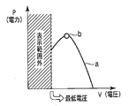
- FIG. 19A shows a PV curve “a” when the DC power P is plotted on the vertical axis and the DC voltage V is plotted on the horizontal axis, and the maximum power point “b” obtained by MPPT control.
- FIG. 19A shows a PV curve “a” when the DC power P is plotted on the vertical axis and the DC voltage V is plotted on the horizontal axis, and the maximum power point “b” obtained by MPPT control.
- FIG. 19B shows the IV curve c and the solar radiation amount d when the vertical axis represents the solar radiation amount and the direct current I, and the horizontal axis represents the direct current voltage V.
- FIG. 19C shows the currents e1, e2, e3 for each of the plurality of solar cell modules of the embodiment of FIG. 5, for example, where the vertical axis represents the DC current I and the horizontal axis represents the DC voltage V.
- FIG. 20A is a diagram showing, for example, the DC power Pdc and the AC power Vac in the embodiment of FIG. 5, where the vertical axis represents the DC power P and the horizontal axis represents the DC voltage V.
- FIG. 20B shows the PV curve f and the maximum power point g when the vertical axis indicates the DC current I and the horizontal axis indicates the DC voltage V.
- FIG. 22 to 24 are display examples in the case where there are a plurality of solar cell arrays.
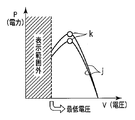
- FIG. 22A shows the PV curve j when the vertical axis indicates DC power P and the horizontal axis indicates DC voltage V, and the maximum power point k obtained by MPPT control.
- FIG. 22B shows the IV curve l and the solar radiation amount m when the vertical axis represents the solar radiation amount and the direct current I, and the horizontal axis represents the direct current voltage V.
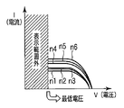
- FIG. 22C shows currents n1, n2, n3, n4, n5, n6 for each of the plurality of solar cell modules in the embodiment of FIG. 5, for example, where the vertical axis represents DC current I and the horizontal axis represents DC voltage V. Yes.
- FIG. 23A is a diagram showing, for example, the DC power Pdc and the AC power Vac in the embodiment of FIG. 5 when the vertical axis indicates the DC power P and the horizontal axis indicates the DC voltage V.
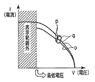
- FIG. 23B shows the PV curve o and the maximum power points p and q when the vertical axis indicates DC current I and the horizontal axis indicates DC voltage V.
- the solar cell array is a plurality of groups, but this may be configured by a group of solar cell arrays.
- the solar cell array is composed of a plurality of solar cell modules, and is provided with a control device capable of displaying the output characteristics of the solar cell array and the power generation conditions of the solar cell array in synchronization with each other. It is.
- a group of solar cell arrays and DC power generated by the solar cell array are converted into desired DC power, which is further converted into AC power and supplied to the AC power system, or the solar cell array
- a power conditioner that converts generated DC power into AC power and supplies the AC power system
- a remote monitoring and control device that monitors and controls the state of the AC power system, and the power generation conditions of the solar cell array are measured
- a communication device is installed in each of the remote monitoring control device, the power conditioner, and the measurement device, and between the communication device of the remote monitoring control device and the communication device of the measurement device, and the communication device of the remote monitoring control device.
- a communication system including a signal transmission path that enables communication with the communication device of the inverter;
- the power conditioner receives a DC voltage command or a DC current command and a control switching command from the remote monitoring control device via the communication system, and the output of the power converter included in the power conditioner is maximized.
- a control switching device for switching from controlling MPPT control to voltage control or current control by the DC voltage command Vref or DC current command Iref;
- a power generation condition detector that is installed in the measurement device and detects a power generation condition of the solar cell array;
- a DC voltage detector that detects a DC voltage that is an output of the solar cell array;
- a direct current detector for detecting a direct current that is an output of the solar cell array;
- Installed in the remote monitoring control device the DC current detection value (I) detected by the DC current detector and the DC voltage detection value (V) detected by the DC voltage detector are taken in, and thereby the solar cell array
- the IV characteristic diagram is traced, and the power generation condition detected by the power generation condition detector is traced to the IV characteristic diagram, and the IV characteristic diagram and the trace of the power generation condition detection value are
- a curve trace device for performing the DC voltage command or the DC current command and the control switching command from the remote monitoring control device in synchronization with transmission to the control switching device and displaying them, Is a photo
- a group of solar cell arrays and DC power generated by the solar cell array are converted into desired DC power, which is further converted into AC power and supplied to the AC power system, or the solar cell array
- a power conditioner that converts generated DC power into AC power and supplies the AC power system
- a remote monitoring and control device that monitors and controls the state of the AC power system, and the power generation conditions of the solar cell array are measured
- a communication device is installed in each of the remote monitoring control device, the power conditioner, and the measurement device, and between the communication device of the remote monitoring control device and the communication device of the measurement device, and the communication device of the remote monitoring control device,
- a communication system including a signal transmission path that enables communication with the communication device of the inverter;
- the power conditioner receives a DC voltage command or a DC current command and a control switching command from the remote monitoring control device via the communication system, and the output of the power converter included in the power conditioner is maximized.
- a control switching device for switching from controlling MPPT control to voltage control or current control by the DC voltage command Vref or DC current command Iref;
- a power generation condition detector that is installed in the measurement device and detects a power generation condition of the solar cell array;
- a DC voltage detector that detects a DC voltage that is an output of the solar cell array;
- a direct current detector for detecting a direct current that is an output of the solar cell array;
- the direct current detection value (I) detected by the direct current detector and the direct current are installed in the remote monitoring control device and synchronized with the transmission of the direct current voltage command or the direct current command from the remote monitoring control device.
- the DC voltage detection value (V) detected by the voltage detector is taken in, the DC power (P) calculated based on the DC voltage detection value (V) and the DC current detection value (I), and the DC voltage detection value ( V) and a PV characteristic diagram are traced and the power generation conditions detected by the power generation condition detector are traced to the PV characteristic diagram, and the PV characteristic diagram and the solar radiation intensity detection are traced.
- the value and the temperature detection value are traced in synchronization with transmission of the DC voltage command or the DC current command and the control switching command from the remote monitoring control device to the control switching device. And the curve trace apparatus that, Is a photovoltaic power generation system.
- a group of solar cell arrays and DC power generated by the solar cell array are converted into desired DC power, which is further converted into AC power and supplied to an AC power system, or the solar cell array
- a power conditioner that converts generated DC power into AC power and supplies the AC power system
- a remote monitoring and control device that monitors and controls the state of the AC power system, and the power generation conditions of the solar cell array are measured
- a communication device is installed in each of the remote monitoring control device, the power conditioner, and the measurement device, and between the communication device of the remote monitoring control device and the communication device of the measurement device, and the communication device of the remote monitoring control device.
- a communication system including a signal transmission path that enables communication with the communication device of the inverter;
- the power conditioner receives a DC voltage command or a DC current command and a control switching command from the remote monitoring control device via the communication system, and the output of the power converter included in the power conditioner is maximized.
- a control switching device for switching from controlling MPPT control to voltage control or current control by the DC voltage command Vref or DC current command Iref;
- a power generation condition detector that is installed in the measurement device and detects a power generation condition of the solar cell array;
- a DC voltage detector that detects a DC voltage that is an output of the solar cell array;
- a direct current detector for detecting a direct current that is an output of the solar cell array;
- the direct current detection value (I) detected by the direct current detector and the direct current are installed in the remote monitoring control device and synchronized with the transmission of the direct current voltage command or the direct current command from the remote monitoring control device.
- the DC voltage detection value (V) detected by the voltage detector is taken in, and the IV characteristic diagram is traced by this, and the calculation is performed based on the DC voltage detection value (V) and the DC current detection value (I).
- a PV characteristic diagram is traced from the DC power (P) and the detected DC voltage value (V), and the power generation condition detected by the power generation condition detector is traced to the PV characteristic diagram.
- the IV characteristic diagram of the solar cell array, the PV characteristic diagram of the solar cell array, and the trace of the power generation condition detection value are transmitted from the remote monitoring control device by the DC voltage command or the DC current command and the A curve tracer for displaying them with the control switching command performed in synchronization with the transmission of to the control switching device, Is a photovoltaic power generation system.
- a group of solar cell arrays and DC power generated by the solar cell array are converted into desired DC power, which is further converted into AC power and supplied to an AC power system, or by the solar cell array
- a power conditioner that converts generated DC power into AC power and supplies the AC power system
- a remote monitoring and control device that monitors and controls the state of the AC power system, and the power generation conditions of the solar cell array are measured
- a communication device is installed in each of the remote monitoring control device, the power conditioner, and the measurement device, and between the communication device of the remote monitoring control device and the communication device of the measurement device, and the communication device of the remote monitoring control device.
- a communication system including a signal transmission path that enables communication with the communication device of the inverter;
- the power conditioner receives a DC voltage command or a DC current command and a control switching command from the remote monitoring control device via the communication system, and the output of the power converter included in the power conditioner is maximized.
- a control switching device for switching from controlling MPPT control to voltage control or current control by the DC voltage command Vref or DC current command Iref;
- a power generation condition detector that is installed in the measurement device and detects a power generation condition of the solar cell array;
- a DC voltage detector that detects a DC voltage that is an output of the solar cell array;
- a direct current detector for detecting a direct current that is an output of the solar cell array;
- An AC power detector that detects AC power that is an output of the power converter;
- the direct current detection value (I) detected by the direct current detector and the direct current are installed in the remote monitoring control device and synchronized with the transmission of the direct current voltage command or the direct current command from the remote monitoring control device.
- the DC voltage detection value (V) detected by the voltage detector is taken in, and the IV characteristic diagram is traced by this, and the calculation is performed based on the DC voltage detection value (V) and the DC current detection value (I).
- the PV characteristic diagram is traced from the DC power (P) and the DC voltage detection value (V), and the power generation condition detected by the power generation condition detector and the AC power detector are detected on the PV characteristic diagram.
- the detected AC power detection value is traced.
- the IV characteristic diagram of the solar cell array, the PV characteristic diagram of the solar cell array, and the trace of the generation condition detection value are traced to the remote monitoring control.
- apparatus A curve tracer for displaying them performs the control switching command and the DC voltage command or the DC current command in synchronization with the transmission of to the control switching device Ri, Is a photovoltaic power generation system.
- a group of solar cell arrays and DC power generated by the solar cell array are converted into desired DC power, which is further converted into AC power and supplied to an AC power system, or the solar cell array
- a power conditioner that converts generated DC power into AC power and supplies the AC power system
- a remote monitoring and control device that monitors and controls the state of the AC power system, and the power generation conditions of the solar cell array are measured
- a communication device is installed in each of the remote monitoring control device, the power conditioner, and the measurement device, and between the communication device of the remote monitoring control device and the communication device of the measurement device, and the communication device of the remote monitoring control device.
- a communication system including a signal transmission path that enables communication with the communication device of the inverter;
- the power conditioner receives a DC voltage command or a DC current command and a control switching command from the remote monitoring control device via the communication system, and the output of the power converter included in the power conditioner is maximized.
- a control switching device for switching from controlling MPPT control to voltage control or current control by the DC voltage command Vref or DC current command Iref;
- a power generation condition detector that is installed in the measurement device and detects a power generation condition of the solar cell array;
- a DC voltage detector that detects a DC voltage that is an output of the solar cell array;
- a direct current detector for detecting a direct current that is an output of the solar cell array;
- the direct current detection value (I) detected by the direct current detector and the direct current are installed in the remote monitoring control device and synchronized with the transmission of the direct current voltage command or the direct current command from the remote monitoring control device.
- the DC voltage detection value (V) detected by the voltage detector is taken in, and the IV characteristic diagram is traced by this, and the calculation is performed based on the DC voltage detection value (V) and the DC current detection value (I).
- the PV characteristic diagram is traced from the DC power (P) and the DC voltage detection value (V), and the power generation condition detected by the power generation condition detector and the AC power detector are detected on the PV characteristic diagram.
- the detected AC power detection value is traced.
- the IV characteristic diagram of the solar cell array, the PV characteristic diagram of the solar cell array, and the trace of the generation condition detection value are traced to the remote monitoring control.
- apparatus A curve tracer for displaying them performs the control switching command and the DC voltage command or the DC current command in synchronization with the transmission of to the control switching device Ri, Is a photovoltaic power generation system.
- the solar power generation system in which the solar cell array is divided into a plurality of solar cell modules, and a DC smoothing capacitor is provided on the input side of the power converter included in the power conditioner, A switch is provided in the electric circuit to which each solar cell module is connected so that any one of the solar cell modules can be selected, and the smoothing capacitor is initially charged simultaneously with the trace operation of the curve trace device.
- This is a photovoltaic power generation system in which an electric circuit switch that makes it possible is provided on the input side of the DC smoothing capacitor.
- Each of the solar cell arrays is composed of a plurality of solar cell array groups, and each solar cell array includes a curve trace device that traces at least the output characteristics of the direct current I and the direct current voltage V, which are outputs of the respective solar cell arrays.
- a photovoltaic power generation system provided with a control device capable of controlling display of each of the curve tracing devices in synchronization.
- the communication system including the communication device and the signal transmission path includes any of a wired communication system, a wireless communication system, a communication system that combines wired communication and wireless communication.
- the present invention is not limited to the above-described large-scale solar power generation system, for example, a megawatt-class solar power generation system or a centrally connected solar power generation system, but is also applicable to an actual machine verification system that evaluates other solar power generation systems and solar power generation battery systems. It goes without saying that it is done.
Abstract
【課題】複数の太陽光発電システムからなる大規模システムでは、カーブトレーサがパワーコンディショナ毎に内蔵されているため、各カーブトレーサを同期して管理制御することできず、同一発電条件下における出力比較による評価が困難であった。 【解決手段】太陽電池アレイ(41…4N)の日射強度を検出可能な日射強度検出器(311…3N1)と、各41…4Nの出力である直流電圧検出値(V)及び各41…4Nの出力である直流電流検出値(I)を、通信装置を介して表示器付のカーブトレース装置(11)を有する遠方監視制御装置(1)に、各41…4Nに対応する直流電圧検出値及び直流電流検出値を同期して入力し、カーブトレース装置(11)により前記I-Vカーブ並びに311…3N1で検出された日射強度検出値に基く日射強度カーブを作成し、これらの作成したカーブを、前記表示器に表示させるようにした太陽光発電システム。
Description
本発明は、大規模な太陽光発電システムや集中連系太陽光発電システムを現地に設置した状態で、例えば遠方監視制御装置により、太陽電池アレイ(PVアレイ)の出力カーブ特性と、発電条件を同期して得ることが可能な太陽光発電システムに関する。
特許文献1(特開2006-201827)には、太陽光発電システムをフィールドに設置した状態で、太陽光発電システムの出力異常を判断するために、パワーコンディショナに、カーブトレーサを内蔵したものが開示されている。
このカーブトレーサは、太陽電池の直流電圧(V)に対応した直流電流(I)を測定し、これから直流電流(I)―直流電圧(V)カーブをトレースし、このトレース結果を表示器に表示させ、この表示器を目視することで太陽光発電システムが正常か異常かを判断することが可能なものである。
特許文献1に記載の発明では、太陽光発電システムの出力を評価するための発電条件である日射強度や気温がトレースされておらず、太陽電池の基準条件(1KW/m2、25℃)からの特性推定値との比較評価が困難であった。
また、複数の太陽光発電システムからなる大規模システムでは、カーブトレーサがパワーコンディショナ毎に内蔵されているため、多数台のカーブトレーサを同期して管理制御することできず、同一発電条件下における複数の太陽光発電システムの出力比較による評価が困難であった。
本発明は、複数個の太陽電池モジュールを含む1群の太陽電池アレイを備えた太陽光発電システムにおいて、前記太陽電池アレイの出力特性と、前記太陽電池アレイの発電条件を同期して表示可能な制御装置を設けたことを特徴する太陽光発電システムである。
また、本発明は、複数の太陽電池アレイ群からなり、各太陽電池アレイ毎に、少なくとも前記太陽電池アレイ毎の出力である、直流電流I及び直流電圧Vの出力特性をトレースするカーブトレース装置を各々備えた太陽光発電システムにおいて、前記各カーブトレース装置を同期して表示制御可能な制御装置を設けたことを特徴とする太陽光発電システムである。
図1は本発明の第1の実施形態を説明するための概略構成図であり、これは複数群の太陽光発電システム101…10Nと、1台の遠方監視制御装置1を備え、各太陽光発電電池システム101…10Nによりそれぞれ発電された直流電力を、パワーコンディショナ21…2Nによりそれぞれ交流電力に変換して商用電源(交流電力系統)5に供給するようになっている。遠方監視制御装置1は前記太陽光発電システム101…10Nの状態を監視制御するものである。
太陽光発電システム101は、1群の太陽電池アレイ41と、太陽電池アレイ41で発電された直流電力を、交流電力に変換して前記交流電力系統5に供給するパワーコンディショナ21と、太陽電池アレイ41とパワーコンディショナ21との間に配設される集電箱81及び電路71と、太陽電池アレイ41の発電条件を計測する計測装置31とを備えている。
太陽光発電システム10Nは、太陽光発電システム101と同様に1群の太陽電池アレイ4Nと、太陽電池アレイ4Nで発電された直流電力を、交流電力に変換して前記交流電力系統5に供給するパワーコンディショナ2Nと、太陽電池アレイ4Nとパワーコンディショナ2Nとの間に配設される集電箱8N及び電路7Nと、太陽電池アレイ4Nの発電条件を計測する計測装置3Nとを備えている。
ここで、太陽電池アレイとは、太陽電池の最小単位である太陽電池セルを複数個組合わせて太陽電池モジュール(太陽電池パネル)を構成し、これら太陽電池モジュールを複数個直列又は並列或いは直並列接続したものを指し、この太陽電池アレイを1個を1群又は単機と呼び、また太陽電池アレイを複数個を複数群又は複数台と呼ぶ。
遠方監視制御装置1及び前記各群のパワーコンディショナ21…2N及び計測装置31…3Nにそれぞれ通信装置12、212…2N2、313…3N3を設置し、遠方監視制御装置1の通信装置12と計測装置31…3Nの通信装置313…3N3との間及び遠方監視制御装置1の通信装置12と各パワーコンディショナ21…2Nの通信装置212…2N2との間を通信可能にする信号伝送路911…9N1、912…9N2、913…9N3を備えた通信システムを有している。
パワーコンディショナ21には、電力変換装置211と、制御切替装置213と、前記通信装置212と、電力変換装置211の入力であって太陽電池アレイ41の出力である直流電圧を検出し、この直流電圧検出値Vdcを前記制御切替装置213及び前記通信装置212に供給する直流電圧検出器214と、電力変換装置211の入力であって太陽電池アレイ41の出力である直流電流を検出し、この直流電流検出値Idcを前記制御切替装置213及び前記通信装置212に供給する直流電流検出器215とを備えている。
制御切替装置213は、遠方監視制御装置1からの直流電圧指令Vref又は直流電流指令Irefと制御切替指令SCANを、前記通信システムを介してパワーコンディショナ21が受信し、パワーコンディショナ21に有する電力変換装置211の出力が最大となるように制御するMPPT(Max Power Point Tracking)制御から前記直流電圧指令Vref又は直流電流指令Irefによる電圧制御又は電流制御に切り替えるものである。
また、パワーコンディショナ2Nも、パワーコンディショナ21と同様に電力変換装置2N1と、制御切替装置2N3と、前記通信装置2N2と、電力変換装置2N1の入力であって太陽電池アレイ4Nの出力である直流電圧を検出し、この直流電圧検出値Vdcを前記制御切替装置2N3及び前記通信装置2N2に供給する直流電圧検出器2N4と、電力変換装置2N1の入力であって太陽電池アレイ4Nの出力である直流電流を検出し、この直流電流検出値Idcを前記制御切替装置2N3及び前記通信装置2N2に供給する直流電流検出器215とを備えている。
制御切替装置2N3は、遠方監視制御装置1から直流電圧指令Vref又は直流電流指令Irefと制御切替指令SCANを、前記通信システムを介してパワーコンディショナ2Nが受信し、パワーコンディショナ2Nに有する電力変換装置2N1の出力が最大となるように制御するMPPT制御から前記直流電圧指令Vref又は直流電流指令Irefによる電圧制御又は電流制御に切り替えるものである。
計測装置31…3Nには、各太陽電池アレイ41…4Nの発電条件である日射強度を計測する日射計311…3N1及び太陽電池アレイ41…4Nが設置されている場所の気温を検出する計測する気温計312…3N2を備えた少なくとも1個(ここでは、太陽電池アレイ41…4N毎に設けられている)の日射強度検出器及び前記通信装置313…3N
3を有している。
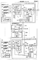
3を有している。
前記遠方監視制御装置1には、以下に述べるカーブトレース装置11及び前記通信装置12を備えている。カーブトレース装置11は、遠方監視制御装置1に設置し、前記各パワーコンディショナ21…2N内に各々有する各直流電流検出器215…2N5で検出した直流電流検出値(I)及び前記各パワーコンディショナ21…2N内に各々有する各直流電圧検出器214…2N4で検出した直流電圧検出値(V)を取り込み、これにより各太陽電池アレイ41…4N毎のI-V特性図をトレースすると共に、各太陽電池アレイ41…4N毎のI-V特性図に前記計測装置31…3Nで検出した日射強度検出値及び気温検出値をトレースするものであって、各太陽電池アレイ41…4N毎のI-V特性図及び前記日射強度検出値及び前記気温検出値のトレースは、遠方監視制御装置1より通信システム、すなわち、通信装置12、信号伝送路912…9N2、通信装置212…2N2を介して前記各パワーコンディショナ21…2N毎に有する制御切替装置213…2N3に対して与えられる直流電圧指令Vref又は直流電流指令Irefと制御切替指令SCANを前記各パワーコンディショナ21…2N毎に有する制御切替装置213…2N3に対しての送信と同期して行うものである。
前記集電箱81…8Nの内部には、太陽電池アレイ41…4Nの出力が各太陽電池アレイ41…4Nを構成している複数個(本実施形態は3個)の太陽電池モジュール側に逆流させないようにするダイオードや、太陽光発電システムの保守点検を行う際に使用する開閉器等が収納されている。
ここで、遠方監視制御装置1とパワーコンディショナ21…N1(このうちの21)間の信号の流れについて、図16及び図17を参照して説明するが、両図とも図1の集電箱
81を省略してある。
81を省略してある。
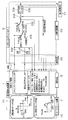
図16はI-Vカーブスキャンの指令データをサンプリング方式で実行するものである。遠方監視制御装置1に有するカーブトレース装置11は、指令データ作成装置111及びI一V持性プロット作成装置112を備えている。
指令データ作成装置111は制御切替指令SCANでスキャンモードオン(ON)オフ(OFF)指令及び直流電圧指令Vrefまたは直流電流指令Iref並びに周期△T例えば1秒毎に指令データを作成し、これにより直流電圧指令値(直流電流指令値)を設定する。
通信装置12は、指令データ作成装置111で設定された直流電圧指令値又は直流電流
指令値を信号伝送路を介してパワーコンディショナ21の通信装置212に送信する。通
信装置212に受信された周期毎で直流電圧指令値(直流電流指令値)を、パワーコンディショナ21に与える。パワーコンディショナ21の制御切替装置213では、スキャンモードがオンなったら、通信によって受信された周期毎で前記直流電圧指令値又は前記直流電流指令値を外部指令としてパワーコンディショナ21に入力し、I-Vカーブスキャンを行う。そして通信装置212は、制御切替装置213の直流電圧指令(直流電圧指令)並びに前記検出器で検出された直流電圧検出値及び直流電流検出値及びこれらに基いて演算された直流電力を通信装置212に送信し(打ち返し)、I-V特性プロット作成装置11ではI-V特性プロットを作成する。
図17はI-Vカーブスキャンの指令データを一括方式で実行するものである。遠方監視制御装置1に有するカーブトレース装置11は、I-V特性プロット作成装置112を備えているが、指令データ作成装置を備えておらず、スキャンモードオン(ON)オフ(OFF)指令及び直流電圧指令値または直流電流指令値並びに周期△T例えば1秒毎に出力するようになっている。パワーコンディショナ21には、直流電圧指令計算式又は直流電流指令計算式を設定できるように設定部2137を備えている。パワーコンディショナ21の制御切替装置213では、スキャンモードがオンなったら、通信によってI-Vカーブスキャンを行い、前記電圧指令及び電流指令並びに周期指令を、前記指令計算式に入力し、前記指令計算式により外部指令が演算される。このようにして求めた直流電圧指令又は直流電流指令を遠方監視制御装置1に通信装置により打ち返し、I-V特性プロット作成装置11ではI-V特性プロットを作成する。
以上述べたカーブトレース装置1の動作は、図14又は図15に示すように行われ、いずれもI-Vカーブスキャンの途中で日射が変動したらI-Vカーブスキャンを停止する。具体的には、図14は、例えば図1及び図16で電圧指令データ作成装置111から
パワーコンディショナ21に対してVref_scanかIref_scanのスキャンモード指令が与えられると(S1)、日射計311…3N1で計測した日射強度が変動がないかどうかを判断し(S2)、日射変動がある場合にはI-Vカーブスキャン終了する(S6)。S2において、日射変動がない場合に、系統異常がないかどうかを判断し(S3)、系統異常がある場合にはI-Vカーブスキャン終了する(S6)。S3において、系統異常がない場合には、I-Vカーブスキャンを実行し(S4)、そのスキャンした値がリミット以上かどうかを判断する(S5)。S5において、リミット以上の場合にはI-Vカーブスキャン終了する(S6)。S6において、リミット以上でない場合にはS2に戻り、日射変動がないかどうかを判断する。なお、S6はスキャン電圧Vref_scanかスキャン電流Iref_sca11が設定したリミットVdcIimitかIdc_limit以上にならない場合、I-Vカーブスキャンを続け、リミットVdc-limitかIdc_limit以上となる場合はI-Vカーブスキャンを終了する。
パワーコンディショナ21に対してVref_scanかIref_scanのスキャンモード指令が与えられると(S1)、日射計311…3N1で計測した日射強度が変動がないかどうかを判断し(S2)、日射変動がある場合にはI-Vカーブスキャン終了する(S6)。S2において、日射変動がない場合に、系統異常がないかどうかを判断し(S3)、系統異常がある場合にはI-Vカーブスキャン終了する(S6)。S3において、系統異常がない場合には、I-Vカーブスキャンを実行し(S4)、そのスキャンした値がリミット以上かどうかを判断する(S5)。S5において、リミット以上の場合にはI-Vカーブスキャン終了する(S6)。S6において、リミット以上でない場合にはS2に戻り、日射変動がないかどうかを判断する。なお、S6はスキャン電圧Vref_scanかスキャン電流Iref_sca11が設定したリミットVdcIimitかIdc_limit以上にならない場合、I-Vカーブスキャンを続け、リミットVdc-limitかIdc_limit以上となる場合はI-Vカーブスキャンを終了する。
I-Vカーブスキャンは、図14と同様に、図15に示すように行われる。I-Vカーブスキャンの途中で日射が変動したらI-Vカーブスキャンを停止する。図15は、I-Vカーブスキャンをグループ毎に動かす場合であり、図14のS1とS2の間にパワーコンディショナ21…2Nの中で選択を行うステップを追加したものである。その選択は、奇数、偶数、太陽電池(PV)モジュール側のストリングコンバータなど自由に選択する。以上述べたステップ以外は、図14と同じであるので、同一部分には同一符号を付してその説明を省略する。
図18は、前述したI-Vカーブスキャンを1日の時間の中での実行する動作時間を説
明するためのものである。図18において、PCS動作時間は、1日の時間の中でPCS
が動作する時間のことである。I-Vカーブスキャン定期時間は、PCS動作時間の中で
I-Vカーブスキャンを定期に行う時間のことである。日射〉設定日射と、I-Vカーブ
スキャン実行トリガは、前述の定期時間の中で日射が設定した日射より大きい場合、I-
Vカーブスキャン実行トリガを出力するが、日射が設定した日射より小さい揚合は、I-
Vカーブスキャン実行トリガの出力をしないことである。この図18の考え方を発展させ
て、外部データを参考とする機能例えば天気予報などの情報取り込む機能を付加すること
で、測定スケジュールを決定するのに効率よいカーブトレースが可能になる。
以上述べた第1の実施形態によれば、太陽光発電システムの出力を評価するための測定条件である日射強度や気温が、カーブトレース装置11でトレースされる特性図に、描かれているので、太陽電池の基準条件(1KW/m2、25℃)からの特性推定値との比較評価が容易に行える。
また、第1の実施形態によれば、複数の太陽光発電システムからなる大規模システムでは、遠方監視制御装置1により複数群の太陽電池アレイ41…4NにおけるI-Vカーブ及び又はP-Vカーブを同期して管理制御することでき、同一発電条件下における複数の太陽光発電システムの出力比較による評価が容易に可能になる。
さらに、太陽光発電システムを現地に設置した状態で、遠方監視制御装置1により、太陽電池アレイ41…4Nの出力カーブ特性と、発電条件を同期して得ることから、太陽電池アレイ41…4Nを容易に評価できる。
また、太陽電池アレイ41…4Nの劣化分析、パワーコンディショナ(PCS)21…2Nの長期間による運転特性分析、正確な最大電力点の判別が可能になる。
さらに、太陽電池アレイ41…4Nの環境、及び、設置条件に伴う日射、気温、日影の影響診断が可能で、太陽電池アレイ41…4Nの劣化や埃、汚れ等による汚損の分析も可能になる。
また、各太陽電池アレイ41…4Nと各パワーコンディショナ21…2N間の配線インピーダンスによる電圧降下の影響診断やパワーコンディショナ21…2Nの運転特性分析、具体的には最高電力点追跡装置(MPPT)の制御性能、損失評価、経年劣化分析が可能になる。
前述した特許文献1で問題であった、次の点を改善できる。すなわち、太陽電池アレイ41…4Nの環境、及び、設置条件に伴う日射、気温、日影の影響診断ができる。また、複数台の太陽光発電システム101…10Nのデータを同期して得ることができる、特性の比較評価を容易にすることができる。さらに、遠方監視制御装置1により太陽電池アレイ41…4Nの出力カーブ特性と、発電条件を同期して得ることができる。
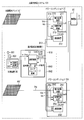
図2は本発明の第2の実施形態を説明するための概略構成図であり、図1の実施形態と異なる点は、図1の実施形態では各群の太陽電池アレイ41…4N毎に、発電条件の一つである日射計311…3N1及び気温計312…3N2を有する計測装置31…3Nを設けたものを、日射計301及び気温計302を有する計測装置30を1個、太陽電池アレイ41…4Nのうち特定の1箇所或いはこれ以外の場所の1箇所に配設したものである。計測装置30で測定した日射計301による日射強度検出値Irr及び気温計302による気温検出値Tmpを、計測装置30に有する通信装置303と、遠方監視制御装置1に有する通信装置12と、これらの間を接続する信号伝送路を介してカーブトレース装置11に伝送するようにしたものである。
図3は本発明の第3の実施形態を説明するための概略構成図であり、図1の実施形態と異なる点は、集電箱81…8Nの代わりに、新たに集電箱81…8Nと直流電流検出器911、912…91M、…9N1、9N2…9NMを備えた集電箱装置91…9Nを設けたものであり、集電箱装置91…9Nは以下のように構成されている。すなわち、各群の太陽電池アレイ41…4Nを各々構成している太陽電池モジュール411、412…41M、…4N1、4N2…4NMと集電箱81…8Nの接続点に直流電流検出器911、912…91M、…9N1、9N2…9NMを設け、集電箱81とパワーコンディショナ21の接続点及び集電箱8Nとパワーコンディショナ2Nの接続点にそれぞれ新たに直流電圧検出器910…9M0を設け、直流電流検出器911、912…91M、…9N1、9N2…9NMの検出値及び直流電圧検出器910…9M0の検出値をそれぞれ通信装置313、12を介してカーブトレース装置11に入力させるようにしたものである。
第3の実施形態によれば、カーブトレース装置11により太陽電池モジュール毎及び太陽電池アレイ毎のI-Vカーブスキャンを行うことができる。
図4は本発明の第4の実施形態を説明するための概略構成図であり、図1の実施形態と異なる点は、計測装置31…3Nを設けず、日射計311…3N1及び気温計312…3N2でそれぞれ計測した日射強度検出値及び気温検出値を通信装置212…2N2及び通信装置12を経由してカーブトレース装置11に入力するように構成したものである。この実施形態は、集中連系型太陽光電池システム例えば住宅用太陽光電池システムに適用できる。
図5は本発明の第5の実施形態を説明するための概略構成図であり、図1の実施形態と異なる点は、発電条件を検出する計測装置31…3Nとして、アレイ又はモジュールの設置場所の日射環境を目視的に確認可能な工業用カメラ3161…316N及び設置場所の風の速さを計る風速計3151…315Nをそれぞれ新たに追加したものである。
このように工業用カメラ3161…316N及び又は風速計3151…315Nを新たに設けたことで、太陽電池特性測定条件のスキャン評価の精度向上を図ることが可能になる。
図6は本発明の第6の実施形態を説明するための概略構成図であり、図1の実施形態と異なる点は、各電力変換装置211…2N1の出力側に新たに交流電圧検出器216…2N6及び交流電流検出器217…2N7を設け、さらにこれらの交流検出値に基き交流電力を演算する交流電力演算器218…2N8を設け、交流電力演算器218…2N8の演算値を通信装置212…2N2及び12を介してカーブトレース装置11に導くようにした点である。この結果、カーブトレース装置11において、直流電力の特性図及び交流電力の特性図を同時に表示できることから、パワーコンディショナ21…2Nまで含めた太陽光発電システムの特性評価が可能になる。
図7は本発明の第7の実施形態を説明するための概略構成図であり、図1の実施形態と異なる点は、集電箱81…8Nを設けない代りに、新たな集電箱装置91…9Nをパワーコンディショナ21…2N内に設けたものであり、集電箱装置91…9Nは以下のように構成されている。すなわち、アレイを構成するモジュール毎の直流電流を検出するために、各モジュールと集電箱81…8Nを接続している直流母線711、712、…71M…7N1、7N2、…7NMにそれぞれ直流電流検出器911、912、…91M…9N1、9N2、…9NMを設け、直流電流検出器911、912、…91M…9N1、9N2、…9NM及び集電箱81…8Nを、それぞれパワーコンディショナ21…2N内に設けた点である。
図8は本発明の第8の実施形態を説明するための概略構成図であり、図1の実施形態と異なる点は、集電箱81…8Nを設けない代りに、新たな集電箱装置91…9Nを設けたものであり、集電箱装置91…9Nは以下のように構成されている。すなわち、アレイを構成する各モジュールとパワーコンディショナ21…2Nの直流母線71…7Nに設けたものであり、集電箱装置91…9Nは以下のように構成されている。すなわち、アレイを構成するモジュール411、412、…41M…4N1、4N2、…4NM毎の直流電流を検出するために、各モジュールと集電箱81…8Nを接続している直流母線71…7Nにそれぞれ直流電流検出器911、912、…91M…9N1、9N2、…9NMを設け、さらに集電箱81…8N内であって前記直流電流検出器911、912、…91M…9N1、9N2、…9NMに対して直列に開閉器811、812…81M及び8N1、8N2…8NMを接続し、開閉器811、812…81M及び8N1、8N2…8NMの動作を、通信装置31…3N、12を介して遠方監視制御装置1のカーブトレース装置11により選択できるように構成したものである。
図9は本発明の第9の実施形態を説明するための概略構成図であり、図1の実施形態と異なる点は、集電箱81…8Nを設けない代りに、新たな集電箱装置91…9Nをパワーコンディショナ21…2N内に設けたものであり、集電箱装置91…9Nは以下のように構成されている。すなわち、アレイを構成するモジュール毎の直流電流を検出するために、各モジュールと集電箱81…8Nを接続している直流母線711、712、…71M…7N1、7N2、…7NMにそれぞれ直流電流検出器911、912、…91M…9N1、9N2、…9NMを設け、直流電流検出器911、912、…91M…9N1、9N2、…9NM及び集電箱81…8Nを、それぞれパワーコンディショナ21…2N内に設け、さらに集電箱81…8N内であって前記直流電流検出器911、912、…91M…9N1、9N2、…9NMに対して直列に開閉器811、812…81M及び8N1、8N2…8NMを接続し、開閉器811、812…81M及び8N1、8N2…8NMの動作を、通信装置212…2N2、12を介して遠方監視制御装置1のカーブトレース装置11により選択できるように構成したものである。
図10は本発明の第10の実施形態を説明するための概略構成図であり、図1の実施形態と異なる点は、図1では集電箱81…8Nと電力系統(商用電源)5の直流母線71…7Nに設けていたパワーコンディショナ21…2Nを設けず、これをアレイ又はモジュール41’…4N7’と集電箱81…8Nの間の直流電路に設け、さらに図1の実施形態では各群の太陽電池アレイ41…4N毎に、発電条件の一つである日射計311…3N1及び気温計312…3N2を有する計測装置31…3Nを設けたものを、日射計301及び気温計302を有する計測装置30を1個、太陽電池アレイ41…4Nのうち特定の1箇所或いはこれ以外の場所の1箇所に配設したものである。
図11は本発明の第11の実施形態を説明するための概略構成図であり、図1の実施形態と異なる点は、図1ではパワーコンディショナ21…2Nの電力変換装置211…2N1の入力側に通常設けられている平滑コンデンサ217…2N7の初期充電を同期して実行できるように次のように構成したものである。すなわち、電力変換装置211…2N1の入力側及び出力側に開閉器216…2N6及び218…2N8をそれぞれ設け、開閉器216…2N6及び218…2N8を通信装置212…2N2及び12を介してカーブトレース装置11により開閉制御することで、平滑コンデンサ217…2N7の初期充電を同期して実行できる。
図12は本発明の第12の実施形態を説明するための概略構成図であり、図1の実施形態と異なる点は、図1ではパワーコンディショナ21…2Nの電力変換装置211…2N1の入力側に通常設けられている平滑コンデンサ217…2N7の初期充電を同期して実行できるように次のように構成したものである。すなわち、パワーコンディショナ21…2Nの例えば通信装置212…2N2にI-Vカーブをスキャンするに必要な、直流電圧検出器214…2N4及び直流電流検出器215…2N5で検出した検出値を一度、記録
する記録装置219…2N9を設け、記録装置219…2N9で記録された直流電圧検出値及び直流電流検出値を通信装置212…2N2及び12を介してカーブトレース装置11により読み出し、これに基きI-Vカーブをスキャンするものである。このようにすることにより、開閉器216…2N6の動作が遅くなった場合にも、I-Vカーブをスキャンすることができる。
する記録装置219…2N9を設け、記録装置219…2N9で記録された直流電圧検出値及び直流電流検出値を通信装置212…2N2及び12を介してカーブトレース装置11により読み出し、これに基きI-Vカーブをスキャンするものである。このようにすることにより、開閉器216…2N6の動作が遅くなった場合にも、I-Vカーブをスキャンすることができる。
図13は本発明の第13の実施形態を説明するための概略構成図であり、図1の実施形態と異なる点は、図1の集電箱81…8Nを設けない代りに、新たな集電箱装置91…9Nをパワーコンディショナ21…2N内に設け、かつ図1ではパワーコンディショナ21…2Nの電力変換装置211…2N1の入力側に通常設けられている平滑コンデンサ217…2N7の初期充電を同期して実行できるように次のように構成したものである。すなわち、集電箱装置91…9Nは以下のように構成されている。
即ち、アレイを構成するモジュール毎の直流電流を検出するために、各モジュールと集電箱81…8Nを接続している直流母線711、712、…71M…7N1、7N2、…7NMにそれぞれ直流電流検出器911、912、…91M…9N1、9N2、…9NMを設け、直流電流検出器911、912、…91M…9N1、9N2、…9NM及び集電箱81…8Nを、それぞれパワーコンディショナ21…2N内に設け、さらに集電箱81…8N内であって前記直流電流検出器911、912、…91M…9N1、9N2、…9NMに対して直列に開閉器811、812…81M及び8N1、8N2…8NMを接続し、開閉器811、812…81M及び8N1、8N2…8NMの動作を、通信装置212…2N2、12を介して遠方監視制御装置1のカーブトレース装置11により選択できるように構成したものである。
また、電力変換装置211…2N1の入力側及び出力側に開閉器216…2N6及び218…2N8をそれぞれ設け、開閉器216…2N6及び218…2N8を通信装置212…2N2及び12を介してカーブトレース装置11により開閉制御することで、平滑コンデンサ217…2N7の初期充電を同期して実行できる。
以下19~図24を用いて、前述の遠方監視制御装置1に備えているカーブトレース装置11に備えている図示しない表示装置或いはカーブトレース装置11に備えている図示しない表示装置及びパワーコンディショナ21…2N内に設けた図示しない表示装置の表示方法について説明する。図19~図21はいずれも太陽電池アレイが1個の場合の表示例である。図19Aは、縦軸に直流電力P、横軸に直流電圧VとしたときのP―Vカーブaと、MPPT制御によって求めた最大電力点bを示している。図19Bは、縦軸に日射量及び直流電流I、横軸に直流電圧VとしたときのI―Vカーブcと、日射量dを示している。図19Cは、縦軸に直流電流I、横軸に直流電圧Vとしたときの例えば図5の実施形態の複数の太陽電池モジュール毎の電流e1、e2、e3を示している。
図20Aは、縦軸に直流電力P、横軸に直流電圧Vとしたとき、例えば図5の実施形態における直流電力Pdcと、交流電力Vacを示す図である。
図20Bは、縦軸に直流電流I、横軸に直流電圧VとしたときのP―Vカーブf及び最大電力点gを示している。
図21は、縦軸に直流電力P、横軸に直流電圧Vとしたとき、例えば図8の実施形態における開閉器811、812、…81Mによる全直流電圧領域におけるP-Vカーブh及び最大電力点iを示す表示例である。
図22~図24はいずれも太陽電池アレイが複数個の場合の表示例である。図22Aは、縦軸に直流電力P、横軸に直流電圧VとしたときのP―Vカーブjと、MPPT制御によって求めた最大電力点kを示している。図22Bは、縦軸に日射量及び直流電流I、横軸に直流電圧VとしたときのI―Vカーブlと、日射量mを示している。図22Cは、縦軸に直流電流I、横軸に直流電圧Vとしたときの例えば図5の実施形態の複数の太陽電池モジュール毎の電流n1、n2、n3、n4、n5、n6を示している。
図23Aは、縦軸に直流電力P、横軸に直流電圧Vとしたとき、例えば図5の実施形態における直流電力Pdcと、交流電力Vacを示す図である。
図23Bは、縦軸に直流電流I、横軸に直流電圧VとしたときのP―Vカーブo及び最大電力点p、qを示している。
図24は、縦軸に直流電力P、横軸に直流電圧Vとしたとき、例えば図8の実施形態における開閉器811、812、…81Mによる全直流電圧領域のP-Vカーブr及び最大電力点s、tを示す表示例である。
次に、本発明の変形例について説明する。前述の実施形態は、いずれも太陽電池アレイが複数群の場合であるが、これを1群の太陽電池アレイで構成してもよい。この場合、太陽電池アレイは、複数の太陽電池モジュールからなっていて、前記太陽電池アレイの出力特性と、前記太陽電池アレイの発電条件を同期して表示可能な制御装置を設けた太陽光発電システムである。
また、1群の太陽電池アレイと、前記太陽電池アレイで発電された直流電力を所望の直流電力に変換しこれを更に交流電力に変換し交流電力系統に供給するか、或いは前記太陽電池アレイで発電された直流電力を交流電力に変換して前記交流電力系統に供給するパワーコンディショナと、前記交流電力系統の状態を監視制御する遠方監視制御装置と、前記太陽電池アレイの発電条件を計測する計測装置とを備えた太陽光発電システムにおいて、
前記遠方監視制御装置及び前記パワーコンディショナ及び前記計測装置にそれぞれ通信装置を設置し、前記遠方監視制御装置の通信装置と前記計測装置の通信装置との間及び前記遠方監視制御装置の通信装置と前記パワーコンディショナの通信装置との間を通信可能にする信号伝送路を備えた通信システムと、
前記遠方監視制御装置から直流電圧指令又は直流電流指令と制御切替指令を、前記通信システムを介して前記パワーコンディショナが受信し、前記パワーコンディショナに有する電力変換装置の出力が最大となるように制御するMPPT制御から前記直流電圧指令Vref又は直流電流指令Irefによる電圧制御又は電流制御に切り替える制御切替装置と、
前記計測装置に設置し、前記太陽電池アレイの発電条件を検出する発電条件検出器と、
前記太陽電池アレイの出力である直流電圧を検出する直流電圧検出器と、
前記太陽電池アレイの出力である直流電流を検出する直流電流検出器と、
前記遠方監視制御装置に設置し、前記直流電流検出器で検出した直流電流検出値(I)及び前記直流電圧検出器で検出した直流電圧検出値(V)を取り込み、これにより前記太陽電池アレイのI-V特性図をトレースすると共に、前記I-V特性図に前記発電条件検出器で検出した発電条件をトレースするものであって、前記I-V特性図及び前記発電条件検出値のトレースは、前記遠方監視制御装置より前記直流電圧指令又は前記直流電流指令と前記制御切替指令を前記制御切替装置に対しての送信と同期して行うとともにこれらを表示するカーブトレース装置と、
を具備した太陽光発電システムである。
さらに、1群の太陽電池アレイと、前記太陽電池アレイで発電された直流電力を所望の直流電力に変換しこれを更に交流電力に変換し交流電力系統に供給するか、或いは前記太陽電池アレイで発電された直流電力を交流電力に変換して前記交流電力系統に供給するパワーコンディショナと、前記交流電力系統の状態を監視制御する遠方監視制御装置と、前記太陽電池アレイの発電条件を計測する計測装置とを備えた太陽光発電システムにおいて、
前記遠方監視制御装置及び前記パワーコンディショナ並びに前記計測装置にそれぞれ通信装置を設置し、前記遠方監視制御装置の通信装置と前記計測装置の通信装置との間及び前記遠方監視制御装置の通信装置と前記パワーコンディショナの通信装置との間を通信可能にする信号伝送路を備えた通信システムと、
前記遠方監視制御装置から直流電圧指令又は直流電流指令と制御切替指令を、前記通信システムを介して前記パワーコンディショナが受信し、前記パワーコンディショナに有する電力変換装置の出力が最大となるように制御するMPPT制御から前記直流電圧指令Vref又は直流電流指令Irefによる電圧制御又は電流制御に切り替える制御切替装置と、
前記計測装置に設置し、前記太陽電池アレイの発電条件を検出する発電条件検出器と、
前記太陽電池アレイの出力である直流電圧を検出する直流電圧検出器と、
前記太陽電池アレイの出力である直流電流を検出する直流電流検出器と、
前記遠方監視制御装置に設置し、かつ前記遠方監視制御装置より前記直流電圧指令又は前記直流電流指令の送信と同期して、前記直流電流検出器で検出した直流電流検出値(I)及び前記直流電圧検出器で検出した直流電圧検出値(V)を取り込み、前記直流電圧検出値(V)及び前記直流電流検出値(I)に基き演算される直流電力(P)と前記直流電圧検出値(V)とからP-V特性図をトレースすると共に、該P-V特性図に前記発電条件検出器で検出した発電条件をトレースするものであって、前記P-V特性図及び前記日射強度検出値及び前記気温検出値のトレースは、前記遠方監視制御装置より前記直流電圧指令又は前記直流電流指令と前記制御切替指令を前記制御切替装置に対しての送信と同期して行うとともにこれらを表示するカーブトレース装置と、
を具備した太陽光発電システムである。
また、 1群の太陽電池アレイと、前記太陽電池アレイで発電された直流電力を所望の直流電力に変換しこれを更に交流電力に変換し交流電力系統に供給するか、或いは前記太陽電池アレイで発電された直流電力を交流電力に変換して前記交流電力系統に供給するパワーコンディショナと、前記交流電力系統の状態を監視制御する遠方監視制御装置と、前記太陽電池アレイの発電条件を計測する計測装置とを備えた太陽光発電システムにおいて、
前記遠方監視制御装置及び前記パワーコンディショナ及び前記計測装置にそれぞれ通信装置を設置し、前記遠方監視制御装置の通信装置と前記計測装置の通信装置との間及び前記遠方監視制御装置の通信装置と前記パワーコンディショナの通信装置との間を通信可能にする信号伝送路を備えた通信システムと、
前記遠方監視制御装置から直流電圧指令又は直流電流指令と制御切替指令を、前記通信システムを介して前記パワーコンディショナが受信し、前記パワーコンディショナに有する電力変換装置の出力が最大となるように制御するMPPT制御から前記直流電圧指令Vref又は直流電流指令Irefによる電圧制御又は電流制御に切り替える制御切替装置と、
前記計測装置に設置し、前記太陽電池アレイの発電条件を検出する発電条件検出器と、
前記太陽電池アレイの出力である直流電圧を検出する直流電圧検出器と、
前記太陽電池アレイの出力である直流電流を検出する直流電流検出器と、
前記遠方監視制御装置に設置し、かつ前記遠方監視制御装置より前記直流電圧指令又は前記直流電流指令の送信と同期して、前記直流電流検出器で検出した直流電流検出値(I)及び前記直流電圧検出器で検出した直流電圧検出値(V)を取り込み、これによりI-V特性図をトレースすると共に、前記直流電圧検出値(V)及び前記直流電流検出値(I)に基き演算される直流電力(P)と前記直流電圧検出値(V)とからP-V特性図をトレースすると共に、該P-V特性図に前記発電条件検出器で検出した発電条件をトレースするものであって、前記太陽電池アレイのI-V特性図及び前記太陽電池アレイのP-V特性図と、前記発電条件検出値のトレースは、前記遠方監視制御装置より前記直流電圧指令又は前記直流電流指令と前記制御切替指令を前記制御切替装置に対しての送信と同期して行うとともにこれらを表示するカーブトレース装置と、
を具備した太陽光発電システムである。
さらに、 1群の太陽電池アレイと、前記太陽電池アレイで発電された直流電力を所望の直流電力に変換しこれを更に交流電力に変換し交流電力系統に供給するか、或いは前記太陽電池アレイで発電された直流電力を交流電力に変換して前記交流電力系統に供給するパワーコンディショナと、前記交流電力系統の状態を監視制御する遠方監視制御装置と、前記太陽電池アレイの発電条件を計測する計測装置とを備えた太陽光発電システムにおいて、
前記遠方監視制御装置及び前記パワーコンディショナ及び前記計測装置にそれぞれ通信装置を設置し、前記遠方監視制御装置の通信装置と前記計測装置の通信装置との間及び前記遠方監視制御装置の通信装置と前記パワーコンディショナの通信装置との間を通信可能にする信号伝送路を備えた通信システムと、
前記遠方監視制御装置から直流電圧指令又は直流電流指令と制御切替指令を、前記通信システムを介して前記パワーコンディショナが受信し、前記パワーコンディショナに有する電力変換装置の出力が最大となるように制御するMPPT制御から前記直流電圧指令Vref又は直流電流指令Irefによる電圧制御又は電流制御に切り替える制御切替装置と、
前記計測装置に設置し、前記太陽電池アレイの発電条件を検出する発電条件検出器と、
前記太陽電池アレイの出力である直流電圧を検出する直流電圧検出器と、
前記太陽電池アレイの出力である直流電流を検出する直流電流検出器と、
前記電力変換装置の出力である交流電力を検出する交流電力検出器と、
前記遠方監視制御装置に設置し、かつ前記遠方監視制御装置より前記直流電圧指令又は前記直流電流指令の送信と同期して、前記直流電流検出器で検出した直流電流検出値(I)及び前記直流電圧検出器で検出した直流電圧検出値(V)を取り込み、これによりI-V特性図をトレースすると共に、前記直流電圧検出値(V)及び前記直流電流検出値(I)に基き演算される直流電力(P)と前記直流電圧検出値(V)とからP-V特性図をトレースすると共に、該P-V特性図に前記発電条件検出器で検出した発電条件及び前記交流電力検出器で検出した交流電力検出値をトレースするものであって、前記太陽電池アレイのI-V特性図及び前記太陽電池アレイのP-V特性図と、前記発電条件検出値のトレースは、前記遠方監視制御装置より前記直流電圧指令又は前記直流電流指令と前記制御切替指令を前記制御切替装置に対しての送信と同期して行うとともにこれらを表示するカーブトレース装置と、
を具備した太陽光発電システムである。
また、 1群の太陽電池アレイと、前記太陽電池アレイで発電された直流電力を所望の直流電力に変換しこれを更に交流電力に変換し交流電力系統に供給するか、或いは前記太陽電池アレイで発電された直流電力を交流電力に変換して前記交流電力系統に供給するパワーコンディショナと、前記交流電力系統の状態を監視制御する遠方監視制御装置と、前記太陽電池アレイの発電条件を計測する計測装置とを備えた太陽光発電システムにおいて、
前記遠方監視制御装置及び前記パワーコンディショナ及び前記計測装置にそれぞれ通信装置を設置し、前記遠方監視制御装置の通信装置と前記計測装置の通信装置との間及び前記遠方監視制御装置の通信装置と前記パワーコンディショナの通信装置との間を通信可能にする信号伝送路を備えた通信システムと、
前記遠方監視制御装置から直流電圧指令又は直流電流指令と制御切替指令を、前記通信システムを介して前記パワーコンディショナが受信し、前記パワーコンディショナに有する電力変換装置の出力が最大となるように制御するMPPT制御から前記直流電圧指令Vref又は直流電流指令Irefによる電圧制御又は電流制御に切り替える制御切替装置と、
前記計測装置に設置し、前記太陽電池アレイの発電条件を検出する発電条件検出器と、
前記太陽電池アレイの出力である直流電圧を検出する直流電圧検出器と、
前記太陽電池アレイの出力である直流電流を検出する直流電流検出器と、
前記遠方監視制御装置に設置し、かつ前記遠方監視制御装置より前記直流電圧指令又は前記直流電流指令の送信と同期して、前記直流電流検出器で検出した直流電流検出値(I)及び前記直流電圧検出器で検出した直流電圧検出値(V)を取り込み、これによりI-V特性図をトレースすると共に、前記直流電圧検出値(V)及び前記直流電流検出値(I)に基き演算される直流電力(P)と前記直流電圧検出値(V)とからP-V特性図をトレースすると共に、該P-V特性図に前記発電条件検出器で検出した発電条件及び前記交流電力検出器で検出した交流電力検出値をトレースするものであって、前記太陽電池アレイのI-V特性図及び前記太陽電池アレイのP-V特性図と、前記発電条件検出値のトレースは、前記遠方監視制御装置より前記直流電圧指令又は前記直流電流指令と前記制御切替指令を前記制御切替装置に対しての送信と同期して行うとともにこれらを表示するカーブトレース装置と、
を具備した太陽光発電システムである。
さらに、前記太陽電池アレイが複数個の太陽電池モジュールに分割され、かつ前記パワーコンディショナに有する電力変換装置の入力側に直流平滑コンデンサを備えている太陽光発電システムにおいて、
前記各太陽電池モジュールのいずれか選択できるように、前記各太陽電池モジュールが接続されている電路に開閉器を設け、更に前記平滑コンデンサの初期充電を、前記カーブトレース装置のトレース動作と同時に行うことを可能にする電路開閉器を、前記直流平滑コンデンサの入力側に設けた太陽光発電システムである。
前記各太陽電池モジュールのいずれか選択できるように、前記各太陽電池モジュールが接続されている電路に開閉器を設け、更に前記平滑コンデンサの初期充電を、前記カーブトレース装置のトレース動作と同時に行うことを可能にする電路開閉器を、前記直流平滑コンデンサの入力側に設けた太陽光発電システムである。
また、複数の太陽電池アレイ群からなり、各太陽電池アレイ毎に、少なくとも前記太陽電池アレイ毎の出力である、直流電流I及び直流電圧Vの出力特性をトレースするカーブトレース装置を各々備えた太陽光発電システムにおいて、前記各カーブトレース装置を同期して表示制御可能な制御装置を設けた太陽光発電システムである。
さらに、前述の説明において、通信装置と信号伝送路を備えた通信システムには、有線通信システム、無線通信システム、有線通信及び無線通信を組合わせた通信システムのいずれかを含むものである。
本発明は前述した大規模例えばメガワット級の太陽光発電システム又は集中連系型太陽光発電システムに限らず、これ以外の太陽光発電システム、太陽光発電電池システムの評価を行う実機検証システムでも適用されることは言うまでもない。
Claims (22)
- 複数個の太陽電池モジュールを含む1群の太陽電池アレイを備えた太陽光発電システムにおいて、
前記太陽電池アレイの出力特性と、前記太陽電池アレイの発電条件を同期して表示可能な制御装置を設けたことを特徴する太陽光発電システム。 - 1群の太陽電池アレイと、前記太陽電池アレイで発電された直流電力を所望の直流電力に変換しこれを更に交流電力に変換し交流電力系統に供給するか、或いは前記太陽電池アレイで発電された直流電力を交流電力に変換して前記交流電力系統に供給するパワーコンディショナと、前記交流電力系統の状態を監視制御する遠方監視制御装置と、前記太陽電池アレイの発電条件を計測する計測装置とを備えた太陽光発電システムにおいて、
前記遠方監視制御装置及び前記パワーコンディショナ及び前記計測装置にそれぞれ通信装置を設置し、前記遠方監視制御装置の通信装置と前記計測装置の通信装置との間及び前記遠方監視制御装置の通信装置と前記パワーコンディショナの通信装置との間を通信可能にする信号伝送路を備えた通信システムと、
前記遠方監視制御装置から直流電圧指令又は直流電流指令と制御切替指令を、前記通信システムを介して前記パワーコンディショナが受信し、前記パワーコンディショナに有する電力変換装置の出力が最大となるように制御するMPPT制御から前記直流電圧指令Vref又は直流電流指令Irefによる電圧制御又は電流制御に切り替える制御切替装置と、
前記計測装置に設置し、前記太陽電池アレイの発電条件を検出する発電条件検出器と、
前記太陽電池アレイの出力である直流電圧を検出する直流電圧検出器と、
前記太陽電池アレイの出力である直流電流を検出する直流電流検出器と、
前記遠方監視制御装置に設置し、前記直流電流検出器で検出した直流電流検出値(I)及び前記直流電圧検出器で検出した直流電圧検出値(V)を取り込み、これにより前記太陽電池アレイのI-V特性図をトレースすると共に、前記I-V特性図に前記発電条件検出器で検出した発電条件をトレースするものであって、前記I-V特性図及び前記発電条件検出値のトレースは、前記遠方監視制御装置より前記直流電圧指令又は前記直流電流指令と前記制御切替指令を前記制御切替装置に対しての送信と同期して行うとともにこれらを表示するカーブトレース装置と、
を具備したことを特徴とする太陽光発電システム。 - 1群の太陽電池アレイと、前記太陽電池アレイで発電された直流電力を所望の直流電力に変換しこれを更に交流電力に変換し交流電力系統に供給するか、或いは前記太陽電池アレイで発電された直流電力を交流電力に変換して前記交流電力系統に供給するパワーコンディショナと、前記交流電力系統の状態を監視制御する遠方監視制御装置と、前記太陽電池アレイの発電条件を計測する計測装置とを備えた太陽光発電システムにおいて、
前記遠方監視制御装置及び前記パワーコンディショナ並びに前記計測装置にそれぞれ通信装置を設置し、前記遠方監視制御装置の通信装置と前記計測装置の通信装置との間及び前記遠方監視制御装置の通信装置と前記パワーコンディショナの通信装置との間を通信可能にする信号伝送路を備えた通信システムと、
前記遠方監視制御装置から直流電圧指令又は直流電流指令と制御切替指令を、前記通信システムを介して前記パワーコンディショナが受信し、前記パワーコンディショナに有する電力変換装置の出力が最大となるように制御するMPPT制御から前記直流電圧指令Vref又は直流電流指令Irefによる電圧制御又は電流制御に切り替える制御切替装置と、
前記計測装置に設置し、前記太陽電池アレイの発電条件を検出する発電条件検出器と、
前記太陽電池アレイの出力である直流電圧を検出する直流電圧検出器と、
前記太陽電池アレイの出力である直流電流を検出する直流電流検出器と、
前記遠方監視制御装置に設置し、かつ前記遠方監視制御装置より前記直流電圧指令又は前記直流電流指令の送信と同期して、前記直流電流検出器で検出した直流電流検出値(I)及び前記直流電圧検出器で検出した直流電圧検出値(V)を取り込み、前記直流電圧検出値(V)及び前記直流電流検出値(I)に基き演算される直流電力(P)と前記直流電圧検出値(V)とからP-V特性図をトレースすると共に、該P-V特性図に前記発電条件検出器で検出した発電条件をトレースするものであって、前記P-V特性図及び前記日射強度検出値及び前記気温検出値のトレースは、前記遠方監視制御装置より前記直流電圧指令又は前記直流電流指令と前記制御切替指令を前記制御切替装置に対しての送信と同期して行うとともにこれらを表示するカーブトレース装置と、
を具備したことを特徴とする太陽光発電システム。 - 1群の太陽電池アレイと、前記太陽電池アレイで発電された直流電力を所望の直流電力に変換しこれを更に交流電力に変換し交流電力系統に供給するか、或いは前記太陽電池アレイで発電された直流電力を交流電力に変換して前記交流電力系統に供給するパワーコンディショナと、前記交流電力系統の状態を監視制御する遠方監視制御装置と、前記太陽電池アレイの発電条件を計測する計測装置とを備えた太陽光発電システムにおいて、
前記遠方監視制御装置及び前記パワーコンディショナ及び前記計測装置にそれぞれ通信装置を設置し、前記遠方監視制御装置の通信装置と前記計測装置の通信装置との間及び前記遠方監視制御装置の通信装置と前記パワーコンディショナの通信装置との間を通信可能にする信号伝送路を備えた通信システムと、
前記遠方監視制御装置から直流電圧指令又は直流電流指令と制御切替指令を、前記通信システムを介して前記パワーコンディショナが受信し、前記パワーコンディショナに有する電力変換装置の出力が最大となるように制御するMPPT制御から前記直流電圧指令Vref又は直流電流指令Irefによる電圧制御又は電流制御に切り替える制御切替装置と、
前記計測装置に設置し、前記太陽電池アレイの発電条件を検出する発電条件検出器と、
前記太陽電池アレイの出力である直流電圧を検出する直流電圧検出器と、
前記太陽電池アレイの出力である直流電流を検出する直流電流検出器と、
前記遠方監視制御装置に設置し、かつ前記遠方監視制御装置より前記直流電圧指令又は前記直流電流指令の送信と同期して、前記直流電流検出器で検出した直流電流検出値(I)及び前記直流電圧検出器で検出した直流電圧検出値(V)を取り込み、これによりI-V特性図をトレースすると共に、前記直流電圧検出値(V)及び前記直流電流検出値(I)に基き演算される直流電力(P)と前記直流電圧検出値(V)とからP-V特性図をトレースすると共に、該P-V特性図に前記発電条件検出器で検出した発電条件をトレースするものであって、前記太陽電池アレイのI-V特性図及び前記太陽電池アレイのP-V特性図と、前記発電条件検出値のトレースは、前記遠方監視制御装置より前記直流電圧指令又は前記直流電流指令と前記制御切替指令を前記制御切替装置に対しての送信と同期して行うとともにこれらを表示するカーブトレース装置と、
を具備したことを特徴とする太陽光発電システム。 - 1群の太陽電池アレイと、前記太陽電池アレイで発電された直流電力を所望の直流電力に変換しこれを更に交流電力に変換し交流電力系統に供給するか、或いは前記太陽電池アレイで発電された直流電力を交流電力に変換して前記交流電力系統に供給するパワーコンディショナと、前記交流電力系統の状態を監視制御する遠方監視制御装置と、前記太陽電池アレイの発電条件を計測する計測装置とを備えた太陽光発電システムにおいて、
前記遠方監視制御装置及び前記パワーコンディショナ及び前記計測装置にそれぞれ通信装置を設置し、前記遠方監視制御装置の通信装置と前記計測装置の通信装置との間及び前記遠方監視制御装置の通信装置と前記パワーコンディショナの通信装置との間を通信可能にする信号伝送路を備えた通信システムと、
前記遠方監視制御装置から直流電圧指令又は直流電流指令と制御切替指令を、前記通信システムを介して前記パワーコンディショナが受信し、前記パワーコンディショナに有する電力変換装置の出力が最大となるように制御するMPPT制御から前記直流電圧指令Vref又は直流電流指令Irefによる電圧制御又は電流制御に切り替える制御切替装置と、
前記計測装置に設置し、前記太陽電池アレイの発電条件を検出する発電条件検出器と、
前記太陽電池アレイの出力である直流電圧を検出する直流電圧検出器と、
前記太陽電池アレイの出力である直流電流を検出する直流電流検出器と、
前記電力変換装置の出力である交流電力を検出する交流電力検出器と、
前記遠方監視制御装置に設置し、かつ前記遠方監視制御装置より前記直流電圧指令又は前記直流電流指令の送信と同期して、前記直流電流検出器で検出した直流電流検出値(I)及び前記直流電圧検出器で検出した直流電圧検出値(V)を取り込み、これによりI-V特性図をトレースすると共に、前記直流電圧検出値(V)及び前記直流電流検出値(I)に基き演算される直流電力(P)と前記直流電圧検出値(V)とからP-V特性図をトレースすると共に、該P-V特性図に前記発電条件検出器で検出した発電条件及び前記交流電力検出器で検出した交流電力検出値をトレースするものであって、前記太陽電池アレイのI-V特性図及び前記太陽電池アレイのP-V特性図と、前記発電条件検出値のトレースは、前記遠方監視制御装置より前記直流電圧指令又は前記直流電流指令と前記制御切替指令を前記制御切替装置に対しての送信と同期して行うとともにこれらを表示するカーブトレース装置と、
を具備したことを特徴とする太陽光発電システム。 - 1群の太陽電池アレイと、前記太陽電池アレイで発電された直流電力を所望の直流電力に変換しこれを更に交流電力に変換し交流電力系統に供給するか、或いは前記太陽電池アレイで発電された直流電力を交流電力に変換して前記交流電力系統に供給するパワーコンディショナと、前記交流電力系統の状態を監視制御する遠方監視制御装置と、前記太陽電池アレイの発電条件を計測する計測装置とを備えた太陽光発電システムにおいて、
前記遠方監視制御装置及び前記パワーコンディショナ及び前記計測装置にそれぞれ通信装置を設置し、前記遠方監視制御装置の通信装置と前記計測装置の通信装置との間及び前記遠方監視制御装置の通信装置と前記パワーコンディショナの通信装置との間を通信可能にする信号伝送路を備えた通信システムと、
前記遠方監視制御装置から直流電圧指令又は直流電流指令と制御切替指令を、前記通信システムを介して前記パワーコンディショナが受信し、前記パワーコンディショナに有する電力変換装置の出力が最大となるように制御するMPPT制御から前記直流電圧指令Vref又は直流電流指令Irefによる電圧制御又は電流制御に切り替える制御切替装置と、
前記計測装置に設置し、前記太陽電池アレイの発電条件を検出する発電条件検出器と、
前記太陽電池アレイの出力である直流電圧を検出する直流電圧検出器と、
前記太陽電池アレイの出力である直流電流を検出する直流電流検出器と、
前記遠方監視制御装置に設置し、かつ前記遠方監視制御装置より前記直流電圧指令又は前記直流電流指令の送信と同期して、前記直流電流検出器で検出した直流電流検出値(I)及び前記直流電圧検出器で検出した直流電圧検出値(V)を取り込み、これによりI-V特性図をトレースすると共に、前記直流電圧検出値(V)及び前記直流電流検出値(I)に基き演算される直流電力(P)と前記直流電圧検出値(V)とからP-V特性図をトレースすると共に、該P-V特性図に前記発電条件検出器で検出した発電条件及び前記交流電力検出器で検出した交流電力検出値をトレースするものであって、前記太陽電池アレイのI-V特性図及び前記太陽電池アレイのP-V特性図と、前記発電条件検出値のトレースは、前記遠方監視制御装置より前記直流電圧指令又は前記直流電流指令と前記制御切替指令を前記制御切替装置に対しての送信と同期して行うとともにこれらを表示するカーブトレース装置と、
を具備したことを特徴とする太陽光発電システム。 - 前記太陽電池アレイが複数個の太陽電池モジュールに分割され、かつ前記パワーコンディショナに有する電力変換装置の入力側に直流平滑コンデンサを備えている太陽光発電システムにおいて、
前記各太陽電池モジュールのいずれか選択できるように、前記各太陽電池モジュールが接続されている電路に開閉器を設け、更に前記平滑コンデンサの初期充電を、前記カーブトレース装置のトレース動作と同時に行うことを可能にする電路開閉器を、前記直流平滑コンデンサの入力側に設けたことを特徴とする請求項2~5のいずれか1項記載の太陽光発電システム。 - 複数の太陽電池アレイ群からなり、各太陽電池アレイ毎に、少なくとも前記太陽電池アレイ毎の出力である、直流電流I及び直流電圧Vの出力特性をトレースするカーブトレース装置を各々備えた太陽光発電システムにおいて、
前記各カーブトレース装置を同期して表示制御可能な制御装置を設けたことを特徴とする太陽光発電システム。 - 複数の太陽電池アレイ群からなり、前記各群の太陽電池アレイで発電された直流電力をそれぞれ所望の直流電力に変換しこれを更に交流電力に変換し交流電力系統に供給するか、或いは前記各群の太陽電池アレイで発電された直流電力を交流電力に変換して前記交流電力系統に供給するパワーコンディショナと、前記交流電力系統の状態を監視制御する遠方監視制御装置と、前記各群の太陽電池アレイの発電条件を計測する計測装置とを備えた太陽光発電システムにおいて、
前記遠方監視制御装置及び前記各群のパワーコンディショナ並びに前記計測装置にそれぞれ通信装置を設置し、前記遠方監視制御装置の通信装置と前記計測装置の通信装置との間及び前記遠方監視制御装置の通信装置と前記各パワーコンディショナの通信装置との間を通信可能にする信号伝送路を備えた通信システムと、
前記遠方監視制御装置から直流電圧指令又は直流電流指令と制御切替指令を、前記通信システムを介して前記各パワーコンディショナが受信し、前記各パワーコンディショナに有する電力変換装置の出力が最大となるように制御するMPPT制御から前記直流電圧指令Vref又は直流電流指令Irefによる電圧制御又は電流制御に切り替える制御切替装置と、
前記太陽電池アレイの発電条件を検出する少なくとも1個の発電条件検出器と、
前記各太陽電池アレイの出力である直流電圧をそれぞれ検出する直流電圧検出器と、
前記各太陽電池アレイの出力である直流電流をそれぞれ検出する直流電流検出器と、
前記遠方監視制御装置に設置し、前記各直流電流検出器で検出した直流電流検出値(I)及び前記直流電圧検出器で検出した直流電圧検出値(V)を取り込み、これにより前記各太陽電池アレイ毎のI-V特性図をトレースすると共に、前記各太陽電池アレイ毎のI-V特性図に前記発電条件検出器で検出した発電条件検出値をトレースするものであって、前記各太陽電池アレイ毎のI-V特性図及び前記発電条件検出値のトレースは、遠方監視制御装置より前記直流電圧指令又は前記直流電流指令と前記制御切替指令を前記制御切替装置に対しての送信と同期して行うとともにこれらを表示するカーブトレース装置と、
を具備したことを特徴とする太陽光発電システム。 - 複数の太陽電池アレイ群からなり、前記各群の太陽電池アレイで発電された直流電力をそれぞれ所望の直流電力に変換しこれを更に交流電力に変換し交流電力系統に供給するか、或いは前記各群の太陽電池アレイで発電された直流電力を交流電力に変換して前記交流電力系統に供給するパワーコンディショナと、前記交流電力系統の状態を監視制御する遠方監視制御装置と、前記各群の太陽電池アレイの発電条件を計測する計測装置とを備えた太陽光発電システムにおいて、
前記遠方監視制御装置及び前記各群のパワーコンディショナ並びに前記計測装置にそれぞれ通信装置を設置し、前記遠方監視制御装置の通信装置と前記計測装置の通信装置との間及び前記遠方監視制御装置の通信装置と前記各パワーコンディショナの通信装置との間を通信可能にする信号伝送路を備えた通信システムと、
前記遠方監視制御装置から直流電圧指令又は直流電流指令と制御切替指令を、前記通信システムを介して前記各パワーコンディショナが受信し、前記各パワーコンディショナに有する電力変換装置の出力が最大となるように制御するMPPT制御から前記直流電圧指令Vref又は直流電流指令Irefによる電圧制御又は電流制御に切り替える制御切替装置と、
前記太陽電池アレイの発電条件である発電条件を検出する少なくとも1個の発電条件検出器と、
前記各太陽電池アレイの出力である直流電圧をそれぞれ検出する直流電圧検出器と、
前記各太陽電池アレイの出力である直流電流をそれぞれ検出する直流電流検出器と、
前記遠方監視制御装置に設置し、前記各直流電流検出器で検出した直流電流検出値(I)及び前記各直流電圧検出器で検出した直流電圧検出値(V)を取り込み、前記各太陽電池アレイ毎の直流電流検出値(I)及び直流電圧検出値(V)に基き演算される直流電力(P)と前記直流電圧検出値(V)とから前記各太陽電池アレイ毎のP-V特性図をトレースすると共に、前記各太陽電池アレイ毎のP-V特性図に前記発電条件検出器で検出した発電条件検出値及び気温検出値をトレースするものであって、前記各太陽電池アレイ毎のP-V特性図及び前記発電条件検出値のトレースは、前記遠方監視制御装置より前記直流電圧指令又は前記直流電流指令と前記制御切替指令を前記制御切替装置に対しての送信と同期して行うとともにこれらを表示するカーブトレース装置と、
を具備したことを特徴とする太陽光発電システム。 - 複数の太陽電池アレイ群からなり、前記各群の太陽電池アレイで発電された直流電力をそれぞれ所望の直流電力に変換しこれを更に交流電力に変換し交流電力系統に供給するか、或いは前記各群の太陽電池アレイで発電された直流電力を交流電力に変換して前記交流電力系統に供給するパワーコンディショナと、前記交流電力系統の状態を監視制御する遠方監視制御装置と、前記各群の太陽電池アレイの発電条件を計測する計測装置とを備えた太陽光発電システムにおいて、
前記遠方監視制御装置及び前記各群のパワーコンディショナ並びに前記計測装置にそれぞれ通信装置を設置し、前記遠方監視制御装置の通信装置と前記計測装置の通信装置との間及び前記遠方監視制御装置の通信装置と前記各パワーコンディショナの通信装置との間を通信可能にする信号伝送路を備えた通信システムと、
前記遠方監視制御装置から直流電圧指令又は直流電流指令と制御切替指令を、前記通信システムを介して前記パワーコンディショナが受信し、前記パワーコンディショナに有する電力変換装置の出力が最大となるように制御する制御切替装置と、
前記太陽電池アレイの発電条件を検出する少なくとも1個の発電条件検出器と、
前記各太陽電池アレイ毎の出力である直流電圧をそれぞれ検出する直流電圧検出器と、
前記各太陽電池アレイ毎の出力である直流電流をそれぞれ検出する直流電流検出器と、
前記遠方監視制御装置に設置し、前記各直流電流検出器で検出した前記各太陽電池アレイ毎の直流電流検出値(I)及び前記各太陽電池アレイ毎の各直流電圧検出器で検出し
た直流電圧検出値(V)を取り込み、これにより前記各太陽電池アレイ毎のI-V特性図をトレースし、かつ前記各太陽電池アレイ毎の直流電流(I)及び直流電圧(V)に基き演算される直流電力(P)と前記直流電圧検出値(V)とから前記各太陽電池アレイ毎のP-V特性図をトレースすると共に、前記各太陽電池アレイ毎のI-V特性図及び前記各太陽電池アレイ毎のP-V特性図に前記発電条件検出器で検出した発電条件検出値をトレースするものであって、前記各太陽電池アレイ毎のI-V特性図及び前記各太陽電池アレイ毎のP-V特性図と、前記発電条件検出値のトレースは、前記遠方監視制御装置より前記直流電圧指令又は前記直流電流指令と前記制御切替指令を前記制御切替装置に対しての送信と同期して行うとともにこれらを表示するカーブトレース装置と、
を具備したことを特徴とする太陽光発電システム。 - 複数の太陽電池アレイ群からなり、前記各群の太陽電池アレイで発電された直流電力をそれぞれ所望の直流電力に変換しこれを更に交流電力に変換し交流電力系統に供給するか、或いは前記各群の太陽電池アレイで発電された直流電力を交流電力に変換して前記交流電力系統に供給するパワーコンディショナと、前記交流電力系統の状態を監視制御する遠方監視制御装置と、前記各群の太陽電池アレイの発電条件を計測する計測装置とを備えた太陽光発電システムにおいて、
前記遠方監視制御装置及び前記各群のパワーコンディショナ並びに前記計測装置にそれぞれ通信装置を設置し、前記遠方監視制御装置の通信装置と前記計測装置の通信装置との間及び前記遠方監視制御装置の通信装置と前記各パワーコンディショナの通信装置との間を通信可能にする信号伝送路を備えた通信システムと、
前記遠方監視制御装置から直流電圧指令又は直流電流指令と制御切替指令を、前記通信システムを介して前記パワーコンディショナが受信し、前記パワーコンディショナに有する電力変換装置の出力が最大となるように制御するMPPT制御から前記直流電圧指令Vref又は直流電流指令Irefによる電圧制御又は電流制御に切り替える制御切替装置と、
前記太陽電池アレイの発電条件を検出する少なくとも1個の日射強度検出器と、
前記各太陽電池アレイ毎の出力である直流電圧をそれぞれ検出する直流電圧検出器と、
前記各太陽電池アレイ毎の出力である直流電流をそれぞれ検出する直流電流検出器と、
前記電力変換装置の出力である交流電力検出器と、
前記遠方監視制御装置に設置し、前記各直流電流検出器で検出した前記各太陽電池アレイ毎の直流電流検出値(I)及び前記各太陽電池アレイ毎の各直流電圧検出器で検出し
た直流電圧検出値(V)を取り込み、これにより前記各太陽電池アレイ毎のI-V特性図をトレースし、かつ前記各太陽電池アレイ毎の直流電流(I)及び直流電圧(V)に基き演算される直流電力(P)と前記直流電圧検出値(V)とから前記各太陽電池アレイ毎のP-V特性図をトレースすると共に、前記各太陽電池アレイ毎のI-V特性図及び前記各太陽電池アレイ毎のP-V特性図に前記発電条件検出器で検出した発電条件検出値及び前記交流電力検出器で検出した交流電力検出値をトレースするものであって、前記各太陽電池アレイ毎のI-V特性図及び前記各太陽電池アレイ毎のP-V特性図と、前記発電条件検出値のトレースは、前記遠方監視制御装置より前記直流電圧指令又は前記直流電流指令と前記制御切替指令を前記制御切替装置に対しての送信と同期して行うとともにこれらを表示するカーブトレース装置と、
を具備したことを特徴とする太陽光発電システム。 - 前記パワーコンディショナに有する電力変換装置の入力側に直流平滑コンデンサを備えている太陽光発電システムにおいて、
前記平滑コンデンサの初期充電を、前記カーブトレース装置のトレース動作と同時に行うことを可能にする電路開閉器を、前記直流平滑コンデンサの入力側に設けたことを特徴とする請求項9~12のいずれか1項記載の太陽光発電システム。 - 前記太陽電池アレイが複数個の太陽電池モジュールに分割され、或いは前記複数群の太陽電池アレイを備え、かつ前記パワーコンディショナに有する電力変換装置の入力側に直流平滑コンデンサを備えている太陽光発電システムにおいて、
前記各太陽電池モジュール又は前記各太陽電池アレイのいずれか選択できるように、前記各太陽電池モジュール又は前記各太陽電池アレイが接続されている電路に開閉器をそれぞれ設け、更に前記平滑コンデンサの初期充電を、前記カーブトレース装置のトレース動作と同時に行うことを可能にする電路開閉器を、前記直流平滑コンデンサの入力側に設けたことを特徴とする請求項9~12のいずれか1項記載の太陽光発電システム。 - 前記発電条件検出器は、前記太陽電池アレイ又は前記太陽電池モジュールの設置場所における、日射強度を計る日射強度計、風の速さを計る風速計、気温を計る気温計のいずれか、又は前記太陽電池アレイ又は前記太陽電池モジュールの温度を計る温度計、若しくは前記太陽電池アレイ又は前記太陽電池モジュールの設置場所における日射環境を視覚的に確認可能なカメラのいずれかである請求項2、3、4、5、9、10、11、12のいずれか1項記載の太陽光発電システム。
- 前記カーブトレース装置でトレースした特性図を目視可能にする表示装置を、前記遠方監視制御装置又は前記遠方監視制御装置及び前記各パワーコンディショナ毎に設置したことを特徴とする請求項2、3、4、5、9、10、11、12のいずれか1項記載の太陽光発電システム。
- 前記表示装置は、前記発電条件検出器、前記直流電圧検出器、前記直流電流検出器、前記交流電力検出器及び前記直流電圧検出器及び前記直流電流検出器から検出した値から直流電力を演算する直流電力演算器の検出値を時間の経過と共に表示するものである2、3、4、5、9、10、11、12のいずれか1項記載の太陽光発電システム。
- 前記表示装置は、前記直流電力演算器の検出値(P)と前記直流電圧検出器の検出値(V)からP-V特性と最大電力点及び前記発電条件検出器の検出値を、前記1群の太陽電池アレイ又は複数群の太陽電池アレイ毎の特性を同時に表示するものである請求項2、3、4、5、9、10、11、12のいずれか1項記載の太陽光発電システム。
- 前記表示装置は、前記直流電流検出器の検出値(I)と前記直流電圧検出器の検出値(V)からI―V特性と前記発電条件検出器の検出値を同時に表示するものである請求項2、3、4、5、9、10、11、12のいずれか1項記載の太陽光発電システム。
- 前記表示装置は、前記直流電流検出器の検出値(I)を、前記1群の太陽電池アレイ又は複数群の太陽電池アレイ毎の特性を同時に表示するものである請求項2、3、4、5、9、10、11、12のいずれか1項記載の太陽光発電システム。
- 前記表示装置は、前記交流電力検出器及び前記直流電圧検出器及び前記直流電流検出器から検出した値から直流電力を演算する直流電力演算器の検出値を時間の経過と共に表示するものである請求項17に記載の太陽光発電システム。
- 前記表示装置は、直流出力側に設けた開閉器より得られる全直流電圧領域おけるP-V特性と最大電力点を同時に表示させるものである請求項13又は14記載の太陽光発電システム。
Priority Applications (7)
| Application Number | Priority Date | Filing Date | Title |
|---|---|---|---|
| CN201080064675.2A CN102770822B (zh) | 2010-02-26 | 2010-02-26 | 太阳能发电系统 |
| PCT/JP2010/053164 WO2011104882A1 (ja) | 2010-02-26 | 2010-02-26 | 太陽光発電システム |
| JP2012501610A JP5531260B2 (ja) | 2010-02-26 | 2010-02-26 | 太陽光発電システム |
| ES10846546T ES2853174T3 (es) | 2010-02-26 | 2010-02-26 | Sistema de generación de potencia |
| EP10846546.9A EP2541364B1 (en) | 2010-02-26 | 2010-02-26 | Power generation system |
| US13/594,020 US9141122B2 (en) | 2010-02-26 | 2012-08-24 | Photovoltaic power generation system |
| JP2014004214A JP5713513B2 (ja) | 2010-02-26 | 2014-01-14 | 太陽光発電システム |
Applications Claiming Priority (1)
| Application Number | Priority Date | Filing Date | Title |
|---|---|---|---|
| PCT/JP2010/053164 WO2011104882A1 (ja) | 2010-02-26 | 2010-02-26 | 太陽光発電システム |
Related Child Applications (1)
| Application Number | Title | Priority Date | Filing Date |
|---|---|---|---|
| US13/594,020 Continuation US9141122B2 (en) | 2010-02-26 | 2012-08-24 | Photovoltaic power generation system |
Publications (1)
| Publication Number | Publication Date |
|---|---|
| WO2011104882A1 true WO2011104882A1 (ja) | 2011-09-01 |
Family
ID=44506325
Family Applications (1)
| Application Number | Title | Priority Date | Filing Date |
|---|---|---|---|
| PCT/JP2010/053164 WO2011104882A1 (ja) | 2010-02-26 | 2010-02-26 | 太陽光発電システム |
Country Status (6)
| Country | Link |
|---|---|
| US (1) | US9141122B2 (ja) |
| EP (1) | EP2541364B1 (ja) |
| JP (1) | JP5531260B2 (ja) |
| CN (1) | CN102770822B (ja) |
| ES (1) | ES2853174T3 (ja) |
| WO (1) | WO2011104882A1 (ja) |
Cited By (8)
| Publication number | Priority date | Publication date | Assignee | Title |
|---|---|---|---|---|
| JP2013187496A (ja) * | 2012-03-09 | 2013-09-19 | Panasonic Corp | 発電制御装置、発電制御システム、および発電制御方法 |
| JP2013192321A (ja) * | 2012-03-13 | 2013-09-26 | Omron Corp | 充電電力制御装置、充電電力制御方法、プログラム、および太陽光発電システム |
| WO2013145079A1 (ja) * | 2012-03-26 | 2013-10-03 | 三菱電機株式会社 | 電力変換装置 |
| JP2013218438A (ja) * | 2012-04-05 | 2013-10-24 | Togami Electric Mfg Co Ltd | 発電出力測定装置 |
| JP2013252046A (ja) * | 2012-05-30 | 2013-12-12 | Taida Electronic Ind Co Ltd | 発電モジュールを含む太陽光発電システム |
| JP2015532578A (ja) * | 2012-10-11 | 2015-11-09 | ウインドストリップ・エルエルシーWindstrip Llc | 多重入力単一出力複合発電システム |
| JP2019054587A (ja) * | 2017-09-13 | 2019-04-04 | 東芝三菱電機産業システム株式会社 | パワーコンディショナシステムおよび太陽光発電システム |
| JP2019161886A (ja) * | 2018-03-14 | 2019-09-19 | オムロン株式会社 | I−vカーブ測定装置 |
Families Citing this family (13)
| Publication number | Priority date | Publication date | Assignee | Title |
|---|---|---|---|---|
| IL215097A (en) * | 2010-09-12 | 2017-05-29 | Rabinovici Raul | Camera controlled solar cell array |
| JP2012085238A (ja) * | 2010-10-14 | 2012-04-26 | Ricoh Co Ltd | 画像処理装置、画像処理装置の電力制御方法、画像処理装置の電力制御プログラム及び記録媒体 |
| JP2013097596A (ja) * | 2011-11-01 | 2013-05-20 | Sony Corp | 太陽電池システム、電子機器および建築物 |
| EP3059653B1 (en) * | 2013-10-15 | 2020-11-25 | Toshiba Mitsubishi-Electric Industrial Systems Corporation | Power conversion device and method for controlling same |
| JP6175514B2 (ja) * | 2013-12-16 | 2017-08-02 | 京セラ株式会社 | 電力制御装置、機器制御装置、及び方法 |
| JP6255251B2 (ja) * | 2014-01-22 | 2017-12-27 | 株式会社日立製作所 | 太陽光発電装置の出力推定方法および装置並びにこれを用いた電力系統監視装置 |
| US10003300B2 (en) * | 2015-10-09 | 2018-06-19 | Sunpower Corporation | Photovoltaic management and module-level power electronics |
| US10439401B2 (en) * | 2015-11-23 | 2019-10-08 | Doosan Gridtech, Inc. | Managing the outflow of a solar inverter |
| JP6410962B2 (ja) * | 2015-11-26 | 2018-10-24 | 三菱電機株式会社 | 配電系統管理装置、計測装置、配電系統管理システムおよび発電量推定方法 |
| JP6132994B1 (ja) * | 2016-05-24 | 2017-05-24 | 三菱電機株式会社 | 配電系統状態推定装置および配電系統状態推定方法 |
| CN106712716B (zh) * | 2017-02-10 | 2019-02-01 | 阳光电源股份有限公司 | 一种光伏组件的iv曲线扫描方法及优化器 |
| CN107800384A (zh) * | 2017-10-19 | 2018-03-13 | 中国电子科技集团公司第四十研究所 | 一种用于光伏组件iv特性对比测试的并发控制方法 |
| TWI765821B (zh) * | 2021-09-13 | 2022-05-21 | 崑山科技大學 | 陰影模式太陽能系統的最大發電功率預測方法 |
Citations (5)
| Publication number | Priority date | Publication date | Assignee | Title |
|---|---|---|---|---|
| JP2000232736A (ja) * | 1999-02-12 | 2000-08-22 | Tdk Corp | 連系分散型発電システム |
| JP2003133569A (ja) * | 2001-10-30 | 2003-05-09 | Atsushi Iga | フィールドにおける太陽電池の出力評価方法・装置 |
| JP2004077309A (ja) * | 2002-08-20 | 2004-03-11 | Atsushi Iga | 太陽電池の出力評価方法,出力評価プログラムを記録したコンピュータ読み取り可能なデータ記録媒体および出力評価装置 |
| JP2005528071A (ja) * | 2002-05-17 | 2005-09-15 | レーリヒ リューディガー | 光起電力装置用回路装置 |
| JP2006201827A (ja) | 2005-01-18 | 2006-08-03 | Omron Corp | カーブトレーサを内蔵したパワーコンディショナおよびカーブトレーサのカーブ評価方法 |
Family Cites Families (21)
| Publication number | Priority date | Publication date | Assignee | Title |
|---|---|---|---|---|
| US4924175A (en) * | 1988-02-29 | 1990-05-08 | Clinton James R | Apparatus for displaying analog signatures of an electronic component |
| JP3474711B2 (ja) | 1996-08-13 | 2003-12-08 | シャープ株式会社 | 連系形太陽光発電装置 |
| JPH10326902A (ja) | 1997-05-26 | 1998-12-08 | Canon Inc | 太陽電池出力特性の測定装置及びその測定方法 |
| US6111767A (en) * | 1998-06-22 | 2000-08-29 | Heliotronics, Inc. | Inverter integrated instrumentation having a current-voltage curve tracer |
| US6239997B1 (en) * | 2000-09-01 | 2001-05-29 | Ford Motor Company | System for connecting and synchronizing a supplemental power source to a power grid |
| JP2002340628A (ja) | 2001-05-18 | 2002-11-27 | Canon Inc | 測定システム |
| FR2844890B1 (fr) * | 2002-09-19 | 2005-01-14 | Cit Alcatel | Circuit de conditionnement pour une source de puissance au point de puissance maximum, generateur solaire et procede de conditionnement |
| JP2005340464A (ja) | 2004-05-26 | 2005-12-08 | Sharp Corp | 太陽電池アレイ診断装置およびそれを用いた太陽光発電システム |
| JP4367251B2 (ja) * | 2004-06-15 | 2009-11-18 | ソニー株式会社 | 電源装置及び電子機器 |
| JP2006101591A (ja) * | 2004-09-28 | 2006-04-13 | Hitachi Cable Ltd | 太陽光発電装置 |
| US8204709B2 (en) * | 2005-01-18 | 2012-06-19 | Solar Sentry Corporation | System and method for monitoring photovoltaic power generation systems |
| US7193872B2 (en) * | 2005-01-28 | 2007-03-20 | Kasemsan Siri | Solar array inverter with maximum power tracking |
| JP5162737B2 (ja) * | 2006-05-17 | 2013-03-13 | 英弘精機株式会社 | 太陽電池の特性評価装置 |
| US7772716B2 (en) * | 2007-03-27 | 2010-08-10 | Newdoll Enterprises Llc | Distributed maximum power point tracking system, structure and process |
| EP1995656A1 (de) * | 2007-05-23 | 2008-11-26 | SMA Solar Technology AG | Verfahren zur Leistungsanpassung |
| US7986539B2 (en) * | 2007-09-26 | 2011-07-26 | Enphase Energy, Inc. | Method and apparatus for maximum power point tracking in power conversion based on dual feedback loops and power ripples |
| WO2009072075A2 (en) * | 2007-12-05 | 2009-06-11 | Solaredge Technologies Ltd. | Photovoltaic system power tracking method |
| JP2009148014A (ja) * | 2007-12-12 | 2009-07-02 | Meidensha Corp | 太陽光発電システムの連系方法 |
| US8106537B2 (en) * | 2008-07-01 | 2012-01-31 | Satcon Technology Corporation | Photovoltaic DC/DC micro-converter |
| WO2010042124A1 (en) * | 2008-10-10 | 2010-04-15 | Ampt, Llc | Novel solar power circuits and powering methods |
| US20100138063A1 (en) * | 2009-08-28 | 2010-06-03 | General Electric Company | Systems and methods for interfacing renewable power sources to a power grid |
-
2010
- 2010-02-26 WO PCT/JP2010/053164 patent/WO2011104882A1/ja active Application Filing
- 2010-02-26 JP JP2012501610A patent/JP5531260B2/ja active Active
- 2010-02-26 CN CN201080064675.2A patent/CN102770822B/zh active Active
- 2010-02-26 EP EP10846546.9A patent/EP2541364B1/en active Active
- 2010-02-26 ES ES10846546T patent/ES2853174T3/es active Active
-
2012
- 2012-08-24 US US13/594,020 patent/US9141122B2/en active Active
Patent Citations (5)
| Publication number | Priority date | Publication date | Assignee | Title |
|---|---|---|---|---|
| JP2000232736A (ja) * | 1999-02-12 | 2000-08-22 | Tdk Corp | 連系分散型発電システム |
| JP2003133569A (ja) * | 2001-10-30 | 2003-05-09 | Atsushi Iga | フィールドにおける太陽電池の出力評価方法・装置 |
| JP2005528071A (ja) * | 2002-05-17 | 2005-09-15 | レーリヒ リューディガー | 光起電力装置用回路装置 |
| JP2004077309A (ja) * | 2002-08-20 | 2004-03-11 | Atsushi Iga | 太陽電池の出力評価方法,出力評価プログラムを記録したコンピュータ読み取り可能なデータ記録媒体および出力評価装置 |
| JP2006201827A (ja) | 2005-01-18 | 2006-08-03 | Omron Corp | カーブトレーサを内蔵したパワーコンディショナおよびカーブトレーサのカーブ評価方法 |
Non-Patent Citations (1)
| Title |
|---|
| See also references of EP2541364A4 * |
Cited By (9)
| Publication number | Priority date | Publication date | Assignee | Title |
|---|---|---|---|---|
| JP2013187496A (ja) * | 2012-03-09 | 2013-09-19 | Panasonic Corp | 発電制御装置、発電制御システム、および発電制御方法 |
| JP2013192321A (ja) * | 2012-03-13 | 2013-09-26 | Omron Corp | 充電電力制御装置、充電電力制御方法、プログラム、および太陽光発電システム |
| WO2013145079A1 (ja) * | 2012-03-26 | 2013-10-03 | 三菱電機株式会社 | 電力変換装置 |
| JP2013218438A (ja) * | 2012-04-05 | 2013-10-24 | Togami Electric Mfg Co Ltd | 発電出力測定装置 |
| JP2013252046A (ja) * | 2012-05-30 | 2013-12-12 | Taida Electronic Ind Co Ltd | 発電モジュールを含む太陽光発電システム |
| JP2015532578A (ja) * | 2012-10-11 | 2015-11-09 | ウインドストリップ・エルエルシーWindstrip Llc | 多重入力単一出力複合発電システム |
| US9979199B2 (en) | 2012-10-11 | 2018-05-22 | Windstrip Llc | Multiple input single output hybrid power system |
| JP2019054587A (ja) * | 2017-09-13 | 2019-04-04 | 東芝三菱電機産業システム株式会社 | パワーコンディショナシステムおよび太陽光発電システム |
| JP2019161886A (ja) * | 2018-03-14 | 2019-09-19 | オムロン株式会社 | I−vカーブ測定装置 |
Also Published As
| Publication number | Publication date |
|---|---|
| CN102770822B (zh) | 2015-03-04 |
| US20130054037A1 (en) | 2013-02-28 |
| JP5531260B2 (ja) | 2014-06-25 |
| US9141122B2 (en) | 2015-09-22 |
| EP2541364B1 (en) | 2020-12-30 |
| EP2541364A1 (en) | 2013-01-02 |
| CN102770822A (zh) | 2012-11-07 |
| ES2853174T3 (es) | 2021-09-15 |
| JPWO2011104882A1 (ja) | 2013-06-17 |
| EP2541364A4 (en) | 2017-04-19 |
Similar Documents
| Publication | Publication Date | Title |
|---|---|---|
| JP5531260B2 (ja) | 太陽光発電システム | |
| US8446043B1 (en) | Photovoltaic array systems, methods, and devices and improved diagnostics and monitoring | |
| KR100912892B1 (ko) | 태양광 발전장치 원격 자가진단 모니터링 및 원격제어시스템 | |
| KR101942806B1 (ko) | 현장 고장 진단이 가능한 이동형 태양광 발전설비 고장 진단시스템 | |
| EP3736866A1 (en) | Monitoring of distributed power harvesting systems using dc power sources | |
| JPWO2013179655A1 (ja) | 太陽光発電監視方法及びその方法に用いられる太陽光発電監視システム | |
| KR20180072244A (ko) | 태양광 발전시스템의 고장진단 제어시스템 및 그 고장진단 제어방법 | |
| JP5713513B2 (ja) | 太陽光発電システム | |
| KR101669847B1 (ko) | 태양 광 발전모듈의 원격 진단시스템 | |
| KR20160125622A (ko) | 태양광 발전장치용 모니터링 장치 | |
| Tyagi et al. | Advance monitoring of electrical and environmental parameters of PV system: a review | |
| KR101656697B1 (ko) | 휴대용 태양광모듈 노화 계측장치 및 그 계측방법 | |
| KR102068014B1 (ko) | 이기종 채널 통신용 모니터링 시스템 | |
| KR101668435B1 (ko) | 태양광 발전 시스템 모니터링 장치 | |
| JP2014232770A (ja) | 太陽光発電システム装置 | |
| KR20120065833A (ko) | 재생에너지 원격 자가진단 모니터링 및 원격제어시스템 | |
| JP2019216547A (ja) | 電力制御装置、太陽光発電システム、太陽光発電設備の不具合診断方法 | |
| CN104143956B (zh) | 太阳能发电系统 | |
| JP5881759B2 (ja) | 太陽光発電システムにおける性能検査装置及びプログラム | |
| JP6320286B2 (ja) | 太陽光発電システムにおける性能検査装置 | |
| KR101113047B1 (ko) | 멀티존 싱글 인버터 태양광 발전 시스템 | |
| Fulzele et al. | PV System With Energy Monitoring to Enhance System Reliability | |
| Valov et al. | System for String Monitoring in small Experimental PV Plants |
Legal Events
| Date | Code | Title | Description |
|---|---|---|---|
| WWE | Wipo information: entry into national phase |
Ref document number: 201080064675.2 Country of ref document: CN |
|
| 121 | Ep: the epo has been informed by wipo that ep was designated in this application |
Ref document number: 10846546 Country of ref document: EP Kind code of ref document: A1 |
|
| WWE | Wipo information: entry into national phase |
Ref document number: 2012501610 Country of ref document: JP |
|
| NENP | Non-entry into the national phase |
Ref country code: DE |
|
| WWE | Wipo information: entry into national phase |
Ref document number: 2010846546 Country of ref document: EP |