WO2011104882A1 - Système de production de puissance photovoltaïque - Google Patents
Système de production de puissance photovoltaïque Download PDFInfo
- Publication number
- WO2011104882A1 WO2011104882A1 PCT/JP2010/053164 JP2010053164W WO2011104882A1 WO 2011104882 A1 WO2011104882 A1 WO 2011104882A1 JP 2010053164 W JP2010053164 W JP 2010053164W WO 2011104882 A1 WO2011104882 A1 WO 2011104882A1
- Authority
- WO
- WIPO (PCT)
- Prior art keywords
- power
- solar cell
- cell array
- voltage
- power generation
- Prior art date
Links
Images


Classifications
-
- G—PHYSICS
- G05—CONTROLLING; REGULATING
- G05F—SYSTEMS FOR REGULATING ELECTRIC OR MAGNETIC VARIABLES
- G05F1/00—Automatic systems in which deviations of an electric quantity from one or more predetermined values are detected at the output of the system and fed back to a device within the system to restore the detected quantity to its predetermined value or values, i.e. retroactive systems
- G05F1/66—Regulating electric power
- G05F1/67—Regulating electric power to the maximum power available from a generator, e.g. from solar cell
-
- Y—GENERAL TAGGING OF NEW TECHNOLOGICAL DEVELOPMENTS; GENERAL TAGGING OF CROSS-SECTIONAL TECHNOLOGIES SPANNING OVER SEVERAL SECTIONS OF THE IPC; TECHNICAL SUBJECTS COVERED BY FORMER USPC CROSS-REFERENCE ART COLLECTIONS [XRACs] AND DIGESTS
- Y02—TECHNOLOGIES OR APPLICATIONS FOR MITIGATION OR ADAPTATION AGAINST CLIMATE CHANGE
- Y02E—REDUCTION OF GREENHOUSE GAS [GHG] EMISSIONS, RELATED TO ENERGY GENERATION, TRANSMISSION OR DISTRIBUTION
- Y02E10/00—Energy generation through renewable energy sources
- Y02E10/50—Photovoltaic [PV] energy
- Y02E10/56—Power conversion systems, e.g. maximum power point trackers
Definitions
- the output curve characteristics of the solar cell array (PV array) and the power generation conditions are controlled by, for example, a remote monitoring control device.
- the present invention relates to a photovoltaic power generation system that can be obtained synchronously.
- Patent Document 1 Japanese Patent Application Laid-Open No. 2006-201827 includes a power conditioner with a built-in curve tracer in order to determine an output abnormality of the photovoltaic power generation system with the photovoltaic power generation system installed in the field. It is disclosed.
- This curve tracer measures the DC current (I) corresponding to the DC voltage (V) of the solar cell, traces the DC current (I) -DC voltage (V) curve, and displays the trace result on the display. It is possible to determine whether the photovoltaic power generation system is normal or abnormal by viewing the display.
- strength and temperature which are the electric power generation conditions for evaluating the output of a solar power generation system are not traced, but it is from the solar cell reference conditions (1KW / m ⁇ 2 >, 25 degreeC). It was difficult to evaluate and compare with the estimated values.
- the present invention can display the output characteristics of the solar cell array and the power generation conditions of the solar cell array in synchronization.
- a solar power generation system characterized by providing a control device.
- the present invention provides a curve trace device that traces output characteristics of a direct current I and a direct current voltage V, which are at least outputs for each solar cell array, for each solar cell array.
- a control device capable of controlling display of each of the curve trace devices in synchronization is provided.
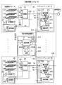
- FIG. 1 is a schematic configuration diagram for explaining a first embodiment of the photovoltaic power generation system of the present invention.
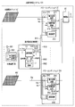
- FIG. 2 is a schematic configuration diagram for explaining a second embodiment of the photovoltaic power generation system of the present invention.
- FIG. 3 is a schematic configuration diagram for explaining a third embodiment of the photovoltaic power generation system of the present invention.
- FIG. 4 is a schematic configuration diagram for explaining a fourth embodiment of the photovoltaic power generation system of the present invention.
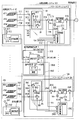
- FIG. 5 is a schematic configuration diagram for explaining a fifth embodiment of the photovoltaic power generation system of the present invention.
- FIG. 6 is a schematic configuration diagram for explaining a sixth embodiment of the photovoltaic power generation system of the present invention.
- FIG. 1 is a schematic configuration diagram for explaining a first embodiment of the photovoltaic power generation system of the present invention.
- FIG. 2 is a schematic configuration diagram for explaining a second embodiment of the photovoltaic power generation system of the present invention.
- FIG. 3 is a
- FIG. 7 is a schematic configuration diagram for explaining a seventh embodiment of the photovoltaic power generation system of the present invention.
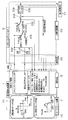
- FIG. 8 is a schematic configuration diagram for explaining an eighth embodiment of the photovoltaic power generation system of the present invention.
- FIG. 9 is a schematic configuration diagram for explaining a ninth embodiment of the photovoltaic power generation system of the present invention.
- FIG. 10 is a schematic configuration diagram for explaining a tenth embodiment of the photovoltaic power generation system of the present invention.
- FIG. 11 is a schematic block diagram for demonstrating 11th Embodiment of the solar energy power generation system of this invention.
- FIG. 12 is a schematic configuration diagram for explaining a twelfth embodiment of the photovoltaic power generation system of the present invention.
- FIG. 13 is a schematic block diagram for demonstrating 13th Embodiment of the solar energy power generation system of this invention.
- FIG. 14 is a flowchart for explaining the operation of the first embodiment of the photovoltaic power generation system of the present invention.
- FIG. 15 is a flowchart for explaining the operation of the first embodiment of the photovoltaic power generation system of the present invention.
- FIG. 16 is an operation explanatory diagram for explaining the operation of each part of the first embodiment in the photovoltaic power generation system of the present invention.
- FIG. 17 is an operation explanatory diagram for explaining the operation of each part of the first embodiment in the photovoltaic power generation system of the present invention.
- FIG. 14 is a flowchart for explaining the operation of the first embodiment of the photovoltaic power generation system of the present invention.
- FIG. 15 is a flowchart for explaining the operation of the first embodiment of the photovoltaic power generation system of the present invention.
- FIG. 16 is an operation explanatory diagram for explaining the operation of each part
- FIG. 18 is an operation explanatory diagram for explaining the operation of each part of the first embodiment in the photovoltaic power generation system of the present invention.
- FIG. 19A is a diagram for explaining a display method of the display device for displaying the output of the curve tracing device in the photovoltaic power generation system of the present invention.
- FIG. 19B is a diagram for explaining a display method of the display device for displaying the output of the curve tracing device in the photovoltaic power generation system of the present invention.
- FIG. 19C is a diagram for explaining a display method of the display device that displays the output of the curve tracing device in the photovoltaic power generation system of the present invention.
- FIG. 19A is a diagram for explaining a display method of the display device for displaying the output of the curve tracing device in the photovoltaic power generation system of the present invention.
- FIG. 19B is a diagram for explaining a display method of the display device for displaying the output of the curve tracing device in the photovolt
- FIG. 20A is a diagram for explaining a display method of the display device that displays the output of the curve tracing device in the photovoltaic power generation system of the present invention.
- FIG. 20B is a diagram for explaining a display method of the display device for displaying the output of the curve tracing device in the photovoltaic power generation system of the present invention.
- FIG. 21 is a diagram for explaining a display method of the display device that displays the output of the curve tracing device in the photovoltaic power generation system of the present invention.
- FIG. 22A is a diagram for explaining a display method of the display device that displays the output of the curve tracing device in the photovoltaic power generation system of the present invention.
- FIG. 20B is a diagram for explaining a display method of the display device for displaying the output of the curve tracing device in the photovoltaic power generation system of the present invention.
- FIG. 21 is a diagram for explaining a display method of the display device that displays the output of the curve tracing device
- FIG. 22B is a diagram for explaining a display method of the display device that displays the output of the curve tracing device in the photovoltaic power generation system of the present invention.
- FIG. 22C is a diagram for explaining a display method of the display device for displaying the output of the curve tracing device in the photovoltaic power generation system of the present invention.
- FIG. 23A is a diagram for explaining a display method of the display device that displays the output of the curve tracing device in the photovoltaic power generation system of the present invention.
- FIG. 23B is a diagram for explaining a display method of the display device that displays the output of the curve tracing device in the photovoltaic power generation system of the present invention.
- FIG. 24 is a diagram for explaining a display method of the display device that displays the output of the curve tracing device in the photovoltaic power generation system of the present invention.
- FIG. 1 is a schematic configuration diagram for explaining a first embodiment of the present invention, which includes a plurality of groups of photovoltaic power generation systems 101...
- the DC power generated by the power generation battery systems 101... 10N is converted into AC power by the power conditioners 21... 2N and supplied to the commercial power source (AC power system) 5.
- the remote monitoring control device 1 monitors and controls the state of the photovoltaic power generation systems 101... 10N.
- the solar power generation system 101 includes a group of solar cell arrays 41, a power conditioner 21 that converts DC power generated by the solar cell array 41 into AC power and supplies the AC power to the AC power system 5, and a solar cell.
- a current collection box 81 and an electric circuit 71 disposed between the array 41 and the power conditioner 21, and a measuring device 31 that measures the power generation conditions of the solar cell array 41 are provided.
- the photovoltaic power generation system 10 ⁇ / b> N converts a group of solar cell arrays 4 ⁇ / b> N and DC power generated by the solar cell array 4 ⁇ / b> N into AC power and supplies the AC power to the AC power system 5.
- a power conditioner 2N, a current collection box 8N and an electric circuit 7N disposed between the solar cell array 4N and the power conditioner 2N, and a measuring device 3N for measuring power generation conditions of the solar cell array 4N are provided. .
- the solar cell array is a combination of a plurality of solar cells, which are the smallest unit of solar cells, to form a solar cell module (solar cell panel).
- This solar cell array is referred to as one group or a single unit, and a plurality of solar cell arrays are referred to as a plurality of groups or a plurality of units.
- Communication devices 12, 212 ... 2N2, 313 ... 3N3 are installed in the remote monitoring control device 1 and the power conditioners 21 ... 2N and the measurement devices 31 ... 3N of the respective groups, respectively, and the communication devices 12 of the remote monitoring control device 1 are measured.
- Signal transmission paths 911 that enable communication between the devices 31... 3N communication devices 313... 3N3 and between the communication devices 12 of the remote monitoring control device 1 and the power conditioners 21. 9N1, 912... 9N2, 913... 9N3.
- the power conditioner 21 detects a DC voltage that is an input of the power conversion device 211, the control switching device 213, the communication device 212, and the power conversion device 211 and an output of the solar cell array 41.
- a DC voltage detector 214 that supplies a voltage detection value Vdc to the control switching device 213 and the communication device 212 and a DC current that is an input of the power conversion device 211 and an output of the solar cell array 41 are detected.
- a DC current detector 215 that supplies a current detection value Idc to the control switching device 213 and the communication device 212.
- the control switching device 213 receives the DC voltage command Vref or the DC current command Iref and the control switching command SCAN from the remote monitoring control device 1 via the communication system, and the power conditioner 21 has power. Switching from MPPT (Max Power Point Tracking) control that controls the output of the converter 211 to a maximum is switched to voltage control or current control by the DC voltage command Vref or DC current command Iref.
- MPPT Maximum Power Point Tracking
- the power conditioner 2N is an input of the power conversion device 2N1, the control switching device 2N3, the communication device 2N2, and the power conversion device 2N1, and is an output of the solar cell array 4N.
- DC voltage detector 2N4 that detects a DC voltage and supplies this DC voltage detection value Vdc to the control switching device 2N3 and the communication device 2N2, and an input of the power converter 2N1 and an output of the solar cell array 4N
- a DC current detector 215 that detects a DC current and supplies the DC current detection value Idc to the control switching device 2N3 and the communication device 2N2 is provided.
- the control switching device 2N3 receives the DC voltage command Vref or DC current command Iref and the control switching command SCAN from the remote monitoring control device 1 via the communication system, and the power converter 2N has power conversion.
- the MPPT control that controls the output of the device 2N1 to the maximum is switched to the voltage control or current control based on the DC voltage command Vref or the DC current command Iref.
- the measuring devices 31... 3N measure the temperature of the places where the solar radiation arrays 311... 3N1 and the solar cell arrays 41. At least one (here, provided for each solar cell array 41... 4N) solar radiation intensity detector including the thermometers 312... 3N2 and the communication devices 313. 3.
- the remote monitoring control device 1 includes a curve trace device 11 and the communication device 12 described below.
- the curve trace device 11 is installed in the remote monitoring control device 1 and the DC current detection values (I) detected by the DC current detectors 215... 2N5 respectively included in the power conditioners 21.
- the DC voltage detection values (V) detected by the DC voltage detectors 214... 2N4 respectively included in the N 21... 2N are fetched, thereby tracing the IV characteristic diagram for each solar cell array 41.
- a solar radiation intensity detection value and an air temperature detection value detected by the measuring devices 31... 3N are traced on an IV characteristic diagram for each solar cell array 41... 4N, and the I for each solar cell array 41.
- the trace of the -V characteristic diagram, the detected solar radiation intensity value, and the detected air temperature value is transmitted from the remote monitoring control device 1 to the communication system, that is, the communication device 12 and the signal transmission path 91. ... 9N2, communication device 212 ... 2N2, and each of the power conditioners 21 ... 2N has a DC voltage command Vref or a DC current command Iref and a control switching command SCAN given to the control switching device 213 ... 2N3. This is performed in synchronism with transmission to the control switching devices 213... 2N3 included in each of the power conditioners 21.
- the outputs of the solar cell arrays 41... 4N flow backward to the plurality of (three in this embodiment) solar cell modules constituting each of the solar cell arrays 41. It contains diodes that are not allowed to be used, switches that are used for maintenance and inspection of the photovoltaic power generation system, and the like.
- FIG. 16 is a diagram for executing the IV curve scan command data by the sampling method.
- the curve tracing device 11 included in the remote monitoring control device 1 includes a command data creation device 111 and an I-V characteristic plot creation device 112.
- the command data creation device 111 creates a command data in response to a control switching command SCAN and creates a scan mode ON (OFF) command, a DC voltage command Vref or a DC current command Iref, and a cycle ⁇ T, for example, every second. Set the voltage command value (DC current command value).
- the communication device 12 transmits the DC voltage command value or the DC current command value set by the command data creation device 111 to the communication device 212 of the power conditioner 21 through the signal transmission path.
- a DC voltage command value (DC current command value) is given to the power conditioner 21 for each cycle received by the communication device 212.
- the control switching device 213 of the power conditioner 21 when the scan mode is turned on, the DC voltage command value or the DC current command value is input to the power conditioner 21 as an external command for each cycle received by communication. -Perform a V curve scan.
- the communication device 212 receives the DC voltage command (DC voltage command) of the control switching device 213, the DC voltage detection value and DC current detection value detected by the detector, and the DC power calculated based on these values.
- the IV characteristic plot creating apparatus 11 creates an IV characteristic plot.
- Fig. 17 shows how to execute command data for IV curve scan in a batch mode.
- the curve tracing device 11 included in the remote monitoring control device 1 includes an IV characteristic plot creation device 112, but does not include a command data creation device, and a scan mode on (ON) off (OFF) command and a direct current.
- the voltage command value or the DC current command value and the period ⁇ T are output every second.
- the power conditioner 21 includes a setting unit 2137 so that a DC voltage command calculation formula or a DC current command calculation formula can be set.
- the control switching device 213 of the inverter 21 performs an IV curve scan by communication, inputs the voltage command, current command, and period command to the command calculation formula, and calculates the command calculation.
- An external command is calculated by the formula.
- the DC voltage command or DC current command thus obtained is returned to the remote monitoring control device 1 by the communication device, and the IV characteristic plot creating device 11 creates an IV characteristic plot.
- the operation of the curve tracing apparatus 1 described above is performed as shown in FIG. 14 or FIG. 15. In either case, if the solar radiation fluctuates during the IV curve scan, the IV curve scan is stopped. Specifically, in FIG. 14, for example, when a scan mode command of Vref_scan or Iref_scan is given from the voltage command data creation device 111 to the power conditioner 21 in FIG. 1 and FIG. 16 (S 1), the pyranometer 311. It is determined whether or not the solar radiation intensity measured in step S2 has a fluctuation (S2). If there is a solar radiation fluctuation, the IV curve scan is terminated (S6). In S2, if there is no variation in solar radiation, it is determined whether there is a system abnormality (S3).
- S3 system abnormality
- the IV curve scan is terminated (S6).
- S3 if there is no system abnormality, an IV curve scan is executed (S4), and it is determined whether the scanned value is equal to or greater than the limit (S5). If the limit is exceeded in S5, the IV curve scan ends (S6).
- S6 when it is not more than the limit, the process returns to S2 and it is determined whether or not there is a variation in solar radiation.
- the scan voltage Vref_scan or the scan current Iref_sca11 does not exceed the set limit VdcIlimit or Idc_limit, the IV curve scan is continued. If the limit Vdc-limit or Idc_limit is greater than the limit, the IV curve scan is terminated .
- the IV curve scan is performed as shown in FIG. 15 as in FIG. If the solar radiation changes during the IV curve scan, the IV curve scan is stopped.
- FIG. 15 shows a case where the IV curve scan is moved for each group, and a step for selecting among the power conditioners 21... 2N is added between S1 and S2 in FIG. The selection is freely selected such as an odd number, an even number, or a string converter on the solar cell (PV) module side. Since steps other than those described above are the same as those in FIG. 14, the same portions are denoted by the same reference numerals and description thereof is omitted.
- FIG. 18 is a diagram for explaining an operation time during which the above-described IV curve scan is performed within a day time.
- the PCS operating time is the PCS within the time of the day. It is the time that operates.
- the IV curve scan periodic time is a period of time during which the IV curve scan is periodically performed during the PCS operation time.
- Solar radiation> set solar radiation and the IV curve scan execution trigger are I- V-curve scan execution trigger is output, but if the solar radiation is less than the set solar radiation, I- The V-curve scan execution trigger is not output.
- the solar radiation intensity and temperature which are measurement conditions for evaluating the output of the photovoltaic power generation system, are drawn on the characteristic diagram traced by the curve tracing device 11. Comparison evaluation with the characteristic estimated value from the standard conditions (1 KW / m 2 , 25 ° C.) of the solar cell can be easily performed.
- the IV curve and / or the PV curve in the plurality of solar cell arrays 41 can be managed and controlled in synchronism with each other, and it is possible to easily evaluate by comparing the outputs of a plurality of photovoltaic power generation systems under the same power generation conditions.
- the solar cell array 41... 4N is obtained by synchronizing the output curve characteristics of the solar cell arrays 41. Can be easily evaluated.
- Patent Document 1 The following points that were problems in Patent Document 1 described above can be improved. That is, the influence of solar radiation, temperature, and shadow according to the environment of the solar cell arrays 41... 4N and installation conditions can be diagnosed. Moreover, the comparative evaluation of the characteristic which can obtain the data of several photovoltaic power generation system 101 ... 10N synchronously can be made easy. Further, the remote monitoring control device 1 can obtain the output curve characteristics of the solar cell arrays 41... 4N and the power generation conditions in synchronization.
- FIG. 2 is a schematic configuration diagram for explaining a second embodiment of the present invention.
- each of the solar cell arrays 41... One of the power generation conditions is provided with the measuring devices 31... 3N having the pyranometers 311... 3N1 and the thermometers 312. 41... 4N are arranged at one specific place or one other place.
- FIG. 3 is a schematic configuration diagram for explaining a third embodiment of the present invention.
- a new current collection box 81... 8 N is used instead of the current collection box 81.
- Current collecting box devices 91... 9 N provided with DC current detectors 911, 912... 91 M,... 9 N 1, 9 N 2 ... 9 NM, and the current collecting box devices 91.
- the direct current detectors 911, 912 are connected to the connection points of the solar cell modules 411, 412 ... 41M,... 4N1, 4N2,. ... 91M, ... 9N1, 9N2, ... 9NM, and DC voltage detectors 910 ...
- 9M0 are newly provided at the connection point between the current collector box 81 and the power conditioner 21 and at the connection point between the current collector box 8N and the power conditioner 2N, respectively. .., 91M,... 9N1, 9N2,... 9NM and DC voltage detectors 910... 9M0 are input to the curve trace device 11 via the communication devices 313 and 12, respectively. It is a thing.
- the curve trace device 11 can perform an IV curve scan for each solar cell module and each solar cell array.
- FIG. 4 is a schematic configuration diagram for explaining a fourth embodiment of the present invention.
- the difference from the embodiment of FIG. 1 is that the measuring devices 31... 3N are not provided, and the pyranometers 311. ... the solar radiation intensity detection value and the temperature detection value respectively measured at 3N2 are input to the curve trace device 11 via the communication devices 212 ... 2N2 and the communication device 12.
- This embodiment can be applied to a concentrated interconnection solar cell system, for example, a residential solar cell system.
- FIG. 5 is a schematic configuration diagram for explaining a fifth embodiment of the present invention, and is different from the embodiment of FIG. 1 in that an installation place of an array or a module as a measuring device 31... 3N for detecting a power generation condition.
- Industrial cameras 3161... 316N and anemometers 3151... 315N that measure the wind speed at the installation location can be newly added.
- FIG. 6 is a schematic configuration diagram for explaining a sixth embodiment of the present invention.
- an AC voltage detector 216 is newly provided on the output side of each power conversion device 211... 2N1.
- ... 2N6 and AC current detectors 217 ... 2N7, AC power calculators 218 ... 2N8 for calculating AC power based on these AC detection values are provided, and the calculated values of the AC power calculators 218 ... 2N8 are transmitted to the communication device 212.
- the curve trace device 11 can simultaneously display the DC power characteristic chart and the AC power characteristic chart, so that it is possible to evaluate the characteristics of the photovoltaic power generation system including the power conditioners 21... 2N.
- FIG. 7 is a schematic configuration diagram for explaining a seventh embodiment of the present invention.
- a new current collection box device is provided instead of providing current collection boxes 81.
- 91 ... 9N are provided in the power conditioners 21 ... 2N, and the current collecting box devices 91 ... 9N are configured as follows. That is, in order to detect the direct current for each module constituting the array, the direct current is applied to the direct current buses 711, 712,... 71M, 7N1, 7N2,. Detectors 911, 912, ... 91M ... 9N1, 9N2, ... 9NM are provided, and DC current detectors 911, 912, ... 91M ... 9N1, 9N2, ... 9NM and current collector box 81 ... 8N are respectively connected to power conditioner 21 ... It is a point provided in 2N.
- FIG. 8 is a schematic configuration diagram for explaining an eighth embodiment of the present invention.
- a new current collection box device is provided instead of providing current collection boxes 81.
- 91 ... 9N are provided, and the current collecting box devices 91 ... 9N are configured as follows. That is, the modules constituting the array and the DC buses 71 ... 7N of the power conditioners 21 ... 2N are provided, and the current collecting box devices 91 ... 9N are configured as follows. That is, in order to detect a direct current for each of the modules 411, 412,... 41M... 4N1, 4N2, ... 4NM constituting the array, the DC buses 71.
- Switches 811, 812... 81M and 8N1, 8N2,... 8NM are connected in series, and the operations of the switches 811, 812 ... 81M and 8N1, 8N2,. It is configured so that it can be selected by the curve tracing device 11 of the monitoring control device 1.
- FIG. 9 is a schematic configuration diagram for explaining a ninth embodiment of the present invention.
- the difference from the embodiment of FIG. 1 is that a new current collection box device is provided instead of providing current collection boxes 81.
- 91 ... 9N are provided in the power conditioners 21 ... 2N, and the current collecting box devices 91 ... 9N are configured as follows. That is, in order to detect the direct current for each module constituting the array, the direct current is applied to the direct current buses 711, 712,... 71M, 7N1, 7N2,. Detectors 911, 912, ... 91M ... 9N1, 9N2, ... 9NM are provided, and DC current detectors 911, 912, ... 91M ... 9N1, 9N2, ...
- 9NM and current collector box 81 ... 8N are respectively connected to power conditioner 21 ... 2N, and further in the current collector box 81 ... 8N, the DC current detectors 911, 912, ... 91M ... 9N1, 9N2, ... 9NM and switches 811, 812 ... 81M and 8N1, 8N2 in series. ... 8NM is connected, and the operations of the switches 811, 812 ... 81M and 8N1, 8N2, ... 8NM are performed through the communication devices 212 ... 2N2,12.
- the curve tracer 11 of the monitor control unit 1 is obtained by configured to allow selection.
- FIG. 10 is a schematic configuration diagram for explaining the tenth embodiment of the present invention.
- the difference from the embodiment of FIG. 1 is that the current collecting boxes 81...
- the power conditioners 21... 2N provided in the DC buses 71... 7N are not provided, but are provided in a DC circuit between the array or modules 41 '... 4N7' and the current collecting boxes 81 ... 8N.
- each of the solar cell arrays 41... 4N of each group is provided with a measuring device 31... 3N having a pyranometer 311... 3N1 and a thermometer 312.
- One measuring device 30 having 302 is disposed at one specific place in the solar cell array 41... 4N or one place other than this.
- FIG. 11 is a schematic configuration diagram for explaining the eleventh embodiment of the present invention.
- the difference from the embodiment of FIG. 1 is that in FIG. 1, the input of the power converters 211... 2N1 of the power conditioners 21.
- the smoothing capacitors 217... 2N7 normally provided on the side are configured as follows so that the initial charging can be performed synchronously. That is, switches 216... 2N6 and 218... 2N8 are provided on the input side and output side of the power converters 211... 2N1, respectively, and the switches 216... 2N6 and 218.
- the initial charging of the smoothing capacitors 217... 2N7 can be executed synchronously.
- FIG. 12 is a schematic configuration diagram for explaining a twelfth embodiment of the present invention.
- the difference from the embodiment of FIG. 1 is that in FIG. 1, the inputs of the power converters 211... 2N1 of the power conditioners 21.
- the smoothing capacitors 217... 2N7 normally provided on the side are configured as follows so that the initial charging can be performed synchronously. That is, the detection values detected by the DC voltage detectors 214... 2N4 and the DC current detectors 215. Recording devices 219... 2N9 for recording are provided, and the DC voltage detection values and DC current detection values recorded by the recording devices 219... 2N9 are read out by the curve trace device 11 via the communication devices 212. -Scan the V curve. By doing so, the IV curve can be scanned even when the operation of the switches 216... 2N6 is delayed.
- FIG. 13 is a schematic configuration diagram for explaining a thirteenth embodiment of the present invention.
- the difference from the embodiment of FIG. 1 is that a new collector is used instead of the current collection boxes 81... 8N of FIG.
- the electrical box devices 91... 9N are provided in the power conditioners 21... 2N, and in FIG. 1, the smoothing capacitors 217... 2N7 normally provided on the input side of the power converters 211. It is configured as follows so that charging can be executed synchronously. That is, the current collecting box devices 91... 9N are configured as follows.
- the direct current is applied to the direct current buses 711, 712,... 71M, 7N1, 7N2,.
- Detectors 911, 912, ... 91M ... 9N1, 9N2, ... 9NM are provided, and DC current detectors 911, 912, ... 91M ... 9N1, 9N2, ... 9NM and current collector box 81 ... 8N are respectively connected to power conditioner 21 ... 2N, and further in the current collector box 81 ... 8N, the DC current detectors 911, 912, ... 91M ... 9N1, 9N2, ... 9NM and switches 811, 812 ... 81M and 8N1, 8N2 in series. ...
- 8NM is connected, and the operations of the switches 811, 812 ... 81M and 8N1, 8N2, ... 8NM are performed remotely via the communication devices 212 ... 2N2,12. It is obtained by configured to be selected by a curve tracer 11 of the control device 1 viewed.
- switches 216... 2N6 and 218... 2N8 are provided on the input side and output side of the power converters 211... 2N1, respectively, and the switches 216... 2N6 and 218.
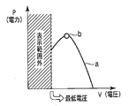
- FIGS. 19 to 21 are display examples in the case where there is only one solar cell array.
- FIG. 19A shows a PV curve “a” when the DC power P is plotted on the vertical axis and the DC voltage V is plotted on the horizontal axis, and the maximum power point “b” obtained by MPPT control.
- FIG. 19A shows a PV curve “a” when the DC power P is plotted on the vertical axis and the DC voltage V is plotted on the horizontal axis, and the maximum power point “b” obtained by MPPT control.
- FIG. 19B shows the IV curve c and the solar radiation amount d when the vertical axis represents the solar radiation amount and the direct current I, and the horizontal axis represents the direct current voltage V.
- FIG. 19C shows the currents e1, e2, e3 for each of the plurality of solar cell modules of the embodiment of FIG. 5, for example, where the vertical axis represents the DC current I and the horizontal axis represents the DC voltage V.
- FIG. 20A is a diagram showing, for example, the DC power Pdc and the AC power Vac in the embodiment of FIG. 5, where the vertical axis represents the DC power P and the horizontal axis represents the DC voltage V.
- FIG. 20B shows the PV curve f and the maximum power point g when the vertical axis indicates the DC current I and the horizontal axis indicates the DC voltage V.
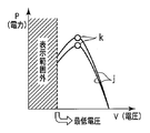
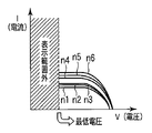
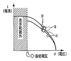
- FIG. 22 to 24 are display examples in the case where there are a plurality of solar cell arrays.
- FIG. 22A shows the PV curve j when the vertical axis indicates DC power P and the horizontal axis indicates DC voltage V, and the maximum power point k obtained by MPPT control.
- FIG. 22B shows the IV curve l and the solar radiation amount m when the vertical axis represents the solar radiation amount and the direct current I, and the horizontal axis represents the direct current voltage V.
- FIG. 22C shows currents n1, n2, n3, n4, n5, n6 for each of the plurality of solar cell modules in the embodiment of FIG. 5, for example, where the vertical axis represents DC current I and the horizontal axis represents DC voltage V. Yes.
- FIG. 23A is a diagram showing, for example, the DC power Pdc and the AC power Vac in the embodiment of FIG. 5 when the vertical axis indicates the DC power P and the horizontal axis indicates the DC voltage V.
- FIG. 23B shows the PV curve o and the maximum power points p and q when the vertical axis indicates DC current I and the horizontal axis indicates DC voltage V.
- the solar cell array is a plurality of groups, but this may be configured by a group of solar cell arrays.
- the solar cell array is composed of a plurality of solar cell modules, and is provided with a control device capable of displaying the output characteristics of the solar cell array and the power generation conditions of the solar cell array in synchronization with each other. It is.
- a group of solar cell arrays and DC power generated by the solar cell array are converted into desired DC power, which is further converted into AC power and supplied to the AC power system, or the solar cell array
- a power conditioner that converts generated DC power into AC power and supplies the AC power system
- a remote monitoring and control device that monitors and controls the state of the AC power system, and the power generation conditions of the solar cell array are measured
- a communication device is installed in each of the remote monitoring control device, the power conditioner, and the measurement device, and between the communication device of the remote monitoring control device and the communication device of the measurement device, and the communication device of the remote monitoring control device.
- a communication system including a signal transmission path that enables communication with the communication device of the inverter;
- the power conditioner receives a DC voltage command or a DC current command and a control switching command from the remote monitoring control device via the communication system, and the output of the power converter included in the power conditioner is maximized.
- a control switching device for switching from controlling MPPT control to voltage control or current control by the DC voltage command Vref or DC current command Iref;
- a power generation condition detector that is installed in the measurement device and detects a power generation condition of the solar cell array;
- a DC voltage detector that detects a DC voltage that is an output of the solar cell array;
- a direct current detector for detecting a direct current that is an output of the solar cell array;
- Installed in the remote monitoring control device the DC current detection value (I) detected by the DC current detector and the DC voltage detection value (V) detected by the DC voltage detector are taken in, and thereby the solar cell array
- the IV characteristic diagram is traced, and the power generation condition detected by the power generation condition detector is traced to the IV characteristic diagram, and the IV characteristic diagram and the trace of the power generation condition detection value are
- a curve trace device for performing the DC voltage command or the DC current command and the control switching command from the remote monitoring control device in synchronization with transmission to the control switching device and displaying them, Is a photo
- a group of solar cell arrays and DC power generated by the solar cell array are converted into desired DC power, which is further converted into AC power and supplied to the AC power system, or the solar cell array
- a power conditioner that converts generated DC power into AC power and supplies the AC power system
- a remote monitoring and control device that monitors and controls the state of the AC power system, and the power generation conditions of the solar cell array are measured
- a communication device is installed in each of the remote monitoring control device, the power conditioner, and the measurement device, and between the communication device of the remote monitoring control device and the communication device of the measurement device, and the communication device of the remote monitoring control device,
- a communication system including a signal transmission path that enables communication with the communication device of the inverter;
- the power conditioner receives a DC voltage command or a DC current command and a control switching command from the remote monitoring control device via the communication system, and the output of the power converter included in the power conditioner is maximized.
- a control switching device for switching from controlling MPPT control to voltage control or current control by the DC voltage command Vref or DC current command Iref;
- a power generation condition detector that is installed in the measurement device and detects a power generation condition of the solar cell array;
- a DC voltage detector that detects a DC voltage that is an output of the solar cell array;
- a direct current detector for detecting a direct current that is an output of the solar cell array;
- the direct current detection value (I) detected by the direct current detector and the direct current are installed in the remote monitoring control device and synchronized with the transmission of the direct current voltage command or the direct current command from the remote monitoring control device.
- the DC voltage detection value (V) detected by the voltage detector is taken in, the DC power (P) calculated based on the DC voltage detection value (V) and the DC current detection value (I), and the DC voltage detection value ( V) and a PV characteristic diagram are traced and the power generation conditions detected by the power generation condition detector are traced to the PV characteristic diagram, and the PV characteristic diagram and the solar radiation intensity detection are traced.
- the value and the temperature detection value are traced in synchronization with transmission of the DC voltage command or the DC current command and the control switching command from the remote monitoring control device to the control switching device. And the curve trace apparatus that, Is a photovoltaic power generation system.
- a group of solar cell arrays and DC power generated by the solar cell array are converted into desired DC power, which is further converted into AC power and supplied to an AC power system, or the solar cell array
- a power conditioner that converts generated DC power into AC power and supplies the AC power system
- a remote monitoring and control device that monitors and controls the state of the AC power system, and the power generation conditions of the solar cell array are measured
- a communication device is installed in each of the remote monitoring control device, the power conditioner, and the measurement device, and between the communication device of the remote monitoring control device and the communication device of the measurement device, and the communication device of the remote monitoring control device.
- a communication system including a signal transmission path that enables communication with the communication device of the inverter;
- the power conditioner receives a DC voltage command or a DC current command and a control switching command from the remote monitoring control device via the communication system, and the output of the power converter included in the power conditioner is maximized.
- a control switching device for switching from controlling MPPT control to voltage control or current control by the DC voltage command Vref or DC current command Iref;
- a power generation condition detector that is installed in the measurement device and detects a power generation condition of the solar cell array;
- a DC voltage detector that detects a DC voltage that is an output of the solar cell array;
- a direct current detector for detecting a direct current that is an output of the solar cell array;
- the direct current detection value (I) detected by the direct current detector and the direct current are installed in the remote monitoring control device and synchronized with the transmission of the direct current voltage command or the direct current command from the remote monitoring control device.
- the DC voltage detection value (V) detected by the voltage detector is taken in, and the IV characteristic diagram is traced by this, and the calculation is performed based on the DC voltage detection value (V) and the DC current detection value (I).
- a PV characteristic diagram is traced from the DC power (P) and the detected DC voltage value (V), and the power generation condition detected by the power generation condition detector is traced to the PV characteristic diagram.
- the IV characteristic diagram of the solar cell array, the PV characteristic diagram of the solar cell array, and the trace of the power generation condition detection value are transmitted from the remote monitoring control device by the DC voltage command or the DC current command and the A curve tracer for displaying them with the control switching command performed in synchronization with the transmission of to the control switching device, Is a photovoltaic power generation system.
- a group of solar cell arrays and DC power generated by the solar cell array are converted into desired DC power, which is further converted into AC power and supplied to an AC power system, or by the solar cell array
- a power conditioner that converts generated DC power into AC power and supplies the AC power system
- a remote monitoring and control device that monitors and controls the state of the AC power system, and the power generation conditions of the solar cell array are measured
- a communication device is installed in each of the remote monitoring control device, the power conditioner, and the measurement device, and between the communication device of the remote monitoring control device and the communication device of the measurement device, and the communication device of the remote monitoring control device.
- a communication system including a signal transmission path that enables communication with the communication device of the inverter;
- the power conditioner receives a DC voltage command or a DC current command and a control switching command from the remote monitoring control device via the communication system, and the output of the power converter included in the power conditioner is maximized.
- a control switching device for switching from controlling MPPT control to voltage control or current control by the DC voltage command Vref or DC current command Iref;
- a power generation condition detector that is installed in the measurement device and detects a power generation condition of the solar cell array;
- a DC voltage detector that detects a DC voltage that is an output of the solar cell array;
- a direct current detector for detecting a direct current that is an output of the solar cell array;
- An AC power detector that detects AC power that is an output of the power converter;
- the direct current detection value (I) detected by the direct current detector and the direct current are installed in the remote monitoring control device and synchronized with the transmission of the direct current voltage command or the direct current command from the remote monitoring control device.
- the DC voltage detection value (V) detected by the voltage detector is taken in, and the IV characteristic diagram is traced by this, and the calculation is performed based on the DC voltage detection value (V) and the DC current detection value (I).
- the PV characteristic diagram is traced from the DC power (P) and the DC voltage detection value (V), and the power generation condition detected by the power generation condition detector and the AC power detector are detected on the PV characteristic diagram.
- the detected AC power detection value is traced.
- the IV characteristic diagram of the solar cell array, the PV characteristic diagram of the solar cell array, and the trace of the generation condition detection value are traced to the remote monitoring control.
- apparatus A curve tracer for displaying them performs the control switching command and the DC voltage command or the DC current command in synchronization with the transmission of to the control switching device Ri, Is a photovoltaic power generation system.
- a group of solar cell arrays and DC power generated by the solar cell array are converted into desired DC power, which is further converted into AC power and supplied to an AC power system, or the solar cell array
- a power conditioner that converts generated DC power into AC power and supplies the AC power system
- a remote monitoring and control device that monitors and controls the state of the AC power system, and the power generation conditions of the solar cell array are measured
- a communication device is installed in each of the remote monitoring control device, the power conditioner, and the measurement device, and between the communication device of the remote monitoring control device and the communication device of the measurement device, and the communication device of the remote monitoring control device.
- a communication system including a signal transmission path that enables communication with the communication device of the inverter;
- the power conditioner receives a DC voltage command or a DC current command and a control switching command from the remote monitoring control device via the communication system, and the output of the power converter included in the power conditioner is maximized.
- a control switching device for switching from controlling MPPT control to voltage control or current control by the DC voltage command Vref or DC current command Iref;
- a power generation condition detector that is installed in the measurement device and detects a power generation condition of the solar cell array;
- a DC voltage detector that detects a DC voltage that is an output of the solar cell array;
- a direct current detector for detecting a direct current that is an output of the solar cell array;
- the direct current detection value (I) detected by the direct current detector and the direct current are installed in the remote monitoring control device and synchronized with the transmission of the direct current voltage command or the direct current command from the remote monitoring control device.
- the DC voltage detection value (V) detected by the voltage detector is taken in, and the IV characteristic diagram is traced by this, and the calculation is performed based on the DC voltage detection value (V) and the DC current detection value (I).
- the PV characteristic diagram is traced from the DC power (P) and the DC voltage detection value (V), and the power generation condition detected by the power generation condition detector and the AC power detector are detected on the PV characteristic diagram.
- the detected AC power detection value is traced.
- the IV characteristic diagram of the solar cell array, the PV characteristic diagram of the solar cell array, and the trace of the generation condition detection value are traced to the remote monitoring control.
- apparatus A curve tracer for displaying them performs the control switching command and the DC voltage command or the DC current command in synchronization with the transmission of to the control switching device Ri, Is a photovoltaic power generation system.
- the solar power generation system in which the solar cell array is divided into a plurality of solar cell modules, and a DC smoothing capacitor is provided on the input side of the power converter included in the power conditioner, A switch is provided in the electric circuit to which each solar cell module is connected so that any one of the solar cell modules can be selected, and the smoothing capacitor is initially charged simultaneously with the trace operation of the curve trace device.
- This is a photovoltaic power generation system in which an electric circuit switch that makes it possible is provided on the input side of the DC smoothing capacitor.
- Each of the solar cell arrays is composed of a plurality of solar cell array groups, and each solar cell array includes a curve trace device that traces at least the output characteristics of the direct current I and the direct current voltage V, which are outputs of the respective solar cell arrays.
- a photovoltaic power generation system provided with a control device capable of controlling display of each of the curve tracing devices in synchronization.
- the communication system including the communication device and the signal transmission path includes any of a wired communication system, a wireless communication system, a communication system that combines wired communication and wireless communication.
- the present invention is not limited to the above-described large-scale solar power generation system, for example, a megawatt-class solar power generation system or a centrally connected solar power generation system, but is also applicable to an actual machine verification system that evaluates other solar power generation systems and solar power generation battery systems. It goes without saying that it is done.
Abstract
Dans un système à grande échelle comprenant une pluralité de systèmes de production de puissance photovoltaïques, puisque des traceurs de courbes sont intégrés dans des conditionneurs de puissance respectifs, il est impossible de gérer et de commander les traceurs de courbes respectifs en synchronisation les uns avec les autres et, par conséquent, il est difficile d'effectuer une évaluation en comparant les sorties dans la même condition de production de puissance.
Les systèmes de production de puissance photovoltaïques comportent des détecteurs d'intensité de rayonnement solaire (311, …, 3N1) qui peuvent détecter l'intensité du rayonnement solaire des matrices photovoltaïques (41, …, 4N). Dans les systèmes de production de puissance photovoltaïques, les valeurs de détection de tension continue (V) et les valeurs de détection de courant continu (I) provenant des matrices photovoltaïques respectives (41, …, 4N) sont transmises, par l'intermédiaire de dispositifs de communication, à un dispositif de commande de télésurveillance (1) comportant un dispositif traceur de courbes (11) comportant une unité d'affichage, tandis que les valeurs de détection de tension continue (V) et les valeurs de détection de courant continu (I) correspondant aux matrices photovoltaïques respectives (41, …, 4N) sont synchronisées les unes avec les autres. Les courbes I et V et les courbes d'intensité de rayonnement solaire basées sur les valeurs d'intensité de rayonnement solaire détectées par les détecteurs d'intensité de rayonnement solaire (311, …, 3N1) sont alors créées par le dispositif traceur de courbes (11), puis les courbes créées sont affichées par l'unité d'affichage.
Priority Applications (7)
| Application Number | Priority Date | Filing Date | Title |
|---|---|---|---|
| CN201080064675.2A CN102770822B (zh) | 2010-02-26 | 2010-02-26 | 太阳能发电系统 |
| EP10846546.9A EP2541364B1 (fr) | 2010-02-26 | 2010-02-26 | Système de production de puissance |
| JP2012501610A JP5531260B2 (ja) | 2010-02-26 | 2010-02-26 | 太陽光発電システム |
| ES10846546T ES2853174T3 (es) | 2010-02-26 | 2010-02-26 | Sistema de generación de potencia |
| PCT/JP2010/053164 WO2011104882A1 (fr) | 2010-02-26 | 2010-02-26 | Système de production de puissance photovoltaïque |
| US13/594,020 US9141122B2 (en) | 2010-02-26 | 2012-08-24 | Photovoltaic power generation system |
| JP2014004214A JP5713513B2 (ja) | 2010-02-26 | 2014-01-14 | 太陽光発電システム |
Applications Claiming Priority (1)
| Application Number | Priority Date | Filing Date | Title |
|---|---|---|---|
| PCT/JP2010/053164 WO2011104882A1 (fr) | 2010-02-26 | 2010-02-26 | Système de production de puissance photovoltaïque |
Related Child Applications (1)
| Application Number | Title | Priority Date | Filing Date |
|---|---|---|---|
| US13/594,020 Continuation US9141122B2 (en) | 2010-02-26 | 2012-08-24 | Photovoltaic power generation system |
Publications (1)
| Publication Number | Publication Date |
|---|---|
| WO2011104882A1 true WO2011104882A1 (fr) | 2011-09-01 |
Family
ID=44506325
Family Applications (1)
| Application Number | Title | Priority Date | Filing Date |
|---|---|---|---|
| PCT/JP2010/053164 WO2011104882A1 (fr) | 2010-02-26 | 2010-02-26 | Système de production de puissance photovoltaïque |
Country Status (6)
| Country | Link |
|---|---|
| US (1) | US9141122B2 (fr) |
| EP (1) | EP2541364B1 (fr) |
| JP (1) | JP5531260B2 (fr) |
| CN (1) | CN102770822B (fr) |
| ES (1) | ES2853174T3 (fr) |
| WO (1) | WO2011104882A1 (fr) |
Cited By (8)
| Publication number | Priority date | Publication date | Assignee | Title |
|---|---|---|---|---|
| JP2013187496A (ja) * | 2012-03-09 | 2013-09-19 | Panasonic Corp | 発電制御装置、発電制御システム、および発電制御方法 |
| JP2013192321A (ja) * | 2012-03-13 | 2013-09-26 | Omron Corp | 充電電力制御装置、充電電力制御方法、プログラム、および太陽光発電システム |
| WO2013145079A1 (fr) * | 2012-03-26 | 2013-10-03 | 三菱電機株式会社 | Dispositif de conversion de puissance |
| JP2013218438A (ja) * | 2012-04-05 | 2013-10-24 | Togami Electric Mfg Co Ltd | 発電出力測定装置 |
| JP2013252046A (ja) * | 2012-05-30 | 2013-12-12 | Taida Electronic Ind Co Ltd | 発電モジュールを含む太陽光発電システム |
| JP2015532578A (ja) * | 2012-10-11 | 2015-11-09 | ウインドストリップ・エルエルシーWindstrip Llc | 多重入力単一出力複合発電システム |
| JP2019054587A (ja) * | 2017-09-13 | 2019-04-04 | 東芝三菱電機産業システム株式会社 | パワーコンディショナシステムおよび太陽光発電システム |
| JP2019161886A (ja) * | 2018-03-14 | 2019-09-19 | オムロン株式会社 | I−vカーブ測定装置 |
Families Citing this family (13)
| Publication number | Priority date | Publication date | Assignee | Title |
|---|---|---|---|---|
| IL215097A (en) * | 2010-09-12 | 2017-05-29 | Rabinovici Raul | Camera controlled solar cell array |
| JP2012085238A (ja) * | 2010-10-14 | 2012-04-26 | Ricoh Co Ltd | 画像処理装置、画像処理装置の電力制御方法、画像処理装置の電力制御プログラム及び記録媒体 |
| JP2013097596A (ja) * | 2011-11-01 | 2013-05-20 | Sony Corp | 太陽電池システム、電子機器および建築物 |
| EP3059653B1 (fr) * | 2013-10-15 | 2020-11-25 | Toshiba Mitsubishi-Electric Industrial Systems Corporation | Dispositif de conversion de puissance et procédé de commande dudit dispositif |
| US10270256B2 (en) * | 2013-12-16 | 2019-04-23 | Kyocera Corporation | Power control apparatus, equipment control apparatus, and method |
| JP6255251B2 (ja) * | 2014-01-22 | 2017-12-27 | 株式会社日立製作所 | 太陽光発電装置の出力推定方法および装置並びにこれを用いた電力系統監視装置 |
| US10003300B2 (en) * | 2015-10-09 | 2018-06-19 | Sunpower Corporation | Photovoltaic management and module-level power electronics |
| US10439401B2 (en) * | 2015-11-23 | 2019-10-08 | Doosan Gridtech, Inc. | Managing the outflow of a solar inverter |
| WO2017090152A1 (fr) * | 2015-11-26 | 2017-06-01 | 三菱電機株式会社 | Dispositif de gestion de système de distribution d'électricité, système de gestion de système de distribution d'électricité, et procédé d'estimation de quantité de génération d'électricité |
| WO2017203611A1 (fr) * | 2016-05-24 | 2017-11-30 | 三菱電機株式会社 | Dispositif d'estimation d'état de système de distribution de puissance électrique et procédé d'estimation d'état de système de distribution de puissance électrique |
| CN106712716B (zh) * | 2017-02-10 | 2019-02-01 | 阳光电源股份有限公司 | 一种光伏组件的iv曲线扫描方法及优化器 |
| CN107800384A (zh) * | 2017-10-19 | 2018-03-13 | 中国电子科技集团公司第四十研究所 | 一种用于光伏组件iv特性对比测试的并发控制方法 |
| TWI765821B (zh) * | 2021-09-13 | 2022-05-21 | 崑山科技大學 | 陰影模式太陽能系統的最大發電功率預測方法 |
Citations (5)
| Publication number | Priority date | Publication date | Assignee | Title |
|---|---|---|---|---|
| JP2000232736A (ja) * | 1999-02-12 | 2000-08-22 | Tdk Corp | 連系分散型発電システム |
| JP2003133569A (ja) * | 2001-10-30 | 2003-05-09 | Atsushi Iga | フィールドにおける太陽電池の出力評価方法・装置 |
| JP2004077309A (ja) * | 2002-08-20 | 2004-03-11 | Atsushi Iga | 太陽電池の出力評価方法,出力評価プログラムを記録したコンピュータ読み取り可能なデータ記録媒体および出力評価装置 |
| JP2005528071A (ja) * | 2002-05-17 | 2005-09-15 | レーリヒ リューディガー | 光起電力装置用回路装置 |
| JP2006201827A (ja) | 2005-01-18 | 2006-08-03 | Omron Corp | カーブトレーサを内蔵したパワーコンディショナおよびカーブトレーサのカーブ評価方法 |
Family Cites Families (21)
| Publication number | Priority date | Publication date | Assignee | Title |
|---|---|---|---|---|
| US4924175A (en) * | 1988-02-29 | 1990-05-08 | Clinton James R | Apparatus for displaying analog signatures of an electronic component |
| JP3474711B2 (ja) | 1996-08-13 | 2003-12-08 | シャープ株式会社 | 連系形太陽光発電装置 |
| JPH10326902A (ja) | 1997-05-26 | 1998-12-08 | Canon Inc | 太陽電池出力特性の測定装置及びその測定方法 |
| US6111767A (en) * | 1998-06-22 | 2000-08-29 | Heliotronics, Inc. | Inverter integrated instrumentation having a current-voltage curve tracer |
| US6239997B1 (en) * | 2000-09-01 | 2001-05-29 | Ford Motor Company | System for connecting and synchronizing a supplemental power source to a power grid |
| JP2002340628A (ja) | 2001-05-18 | 2002-11-27 | Canon Inc | 測定システム |
| FR2844890B1 (fr) * | 2002-09-19 | 2005-01-14 | Cit Alcatel | Circuit de conditionnement pour une source de puissance au point de puissance maximum, generateur solaire et procede de conditionnement |
| JP2005340464A (ja) | 2004-05-26 | 2005-12-08 | Sharp Corp | 太陽電池アレイ診断装置およびそれを用いた太陽光発電システム |
| JP4367251B2 (ja) * | 2004-06-15 | 2009-11-18 | ソニー株式会社 | 電源装置及び電子機器 |
| JP2006101591A (ja) * | 2004-09-28 | 2006-04-13 | Hitachi Cable Ltd | 太陽光発電装置 |
| US8204709B2 (en) * | 2005-01-18 | 2012-06-19 | Solar Sentry Corporation | System and method for monitoring photovoltaic power generation systems |
| US7193872B2 (en) * | 2005-01-28 | 2007-03-20 | Kasemsan Siri | Solar array inverter with maximum power tracking |
| JP5162737B2 (ja) * | 2006-05-17 | 2013-03-13 | 英弘精機株式会社 | 太陽電池の特性評価装置 |
| US7772716B2 (en) * | 2007-03-27 | 2010-08-10 | Newdoll Enterprises Llc | Distributed maximum power point tracking system, structure and process |
| EP1995656A1 (fr) * | 2007-05-23 | 2008-11-26 | SMA Solar Technology AG | Procédé d'adaptation à la puissance |
| US7986539B2 (en) * | 2007-09-26 | 2011-07-26 | Enphase Energy, Inc. | Method and apparatus for maximum power point tracking in power conversion based on dual feedback loops and power ripples |
| US9291696B2 (en) * | 2007-12-05 | 2016-03-22 | Solaredge Technologies Ltd. | Photovoltaic system power tracking method |
| JP2009148014A (ja) * | 2007-12-12 | 2009-07-02 | Meidensha Corp | 太陽光発電システムの連系方法 |
| US8106537B2 (en) * | 2008-07-01 | 2012-01-31 | Satcon Technology Corporation | Photovoltaic DC/DC micro-converter |
| WO2010042124A1 (fr) * | 2008-10-10 | 2010-04-15 | Ampt, Llc | Nouveaux circuits à énergie solaire et procédés d'alimentation électrique |
| US20100138063A1 (en) * | 2009-08-28 | 2010-06-03 | General Electric Company | Systems and methods for interfacing renewable power sources to a power grid |
-
2010
- 2010-02-26 WO PCT/JP2010/053164 patent/WO2011104882A1/fr active Application Filing
- 2010-02-26 EP EP10846546.9A patent/EP2541364B1/fr active Active
- 2010-02-26 JP JP2012501610A patent/JP5531260B2/ja active Active
- 2010-02-26 ES ES10846546T patent/ES2853174T3/es active Active
- 2010-02-26 CN CN201080064675.2A patent/CN102770822B/zh active Active
-
2012
- 2012-08-24 US US13/594,020 patent/US9141122B2/en active Active
Patent Citations (5)
| Publication number | Priority date | Publication date | Assignee | Title |
|---|---|---|---|---|
| JP2000232736A (ja) * | 1999-02-12 | 2000-08-22 | Tdk Corp | 連系分散型発電システム |
| JP2003133569A (ja) * | 2001-10-30 | 2003-05-09 | Atsushi Iga | フィールドにおける太陽電池の出力評価方法・装置 |
| JP2005528071A (ja) * | 2002-05-17 | 2005-09-15 | レーリヒ リューディガー | 光起電力装置用回路装置 |
| JP2004077309A (ja) * | 2002-08-20 | 2004-03-11 | Atsushi Iga | 太陽電池の出力評価方法,出力評価プログラムを記録したコンピュータ読み取り可能なデータ記録媒体および出力評価装置 |
| JP2006201827A (ja) | 2005-01-18 | 2006-08-03 | Omron Corp | カーブトレーサを内蔵したパワーコンディショナおよびカーブトレーサのカーブ評価方法 |
Non-Patent Citations (1)
| Title |
|---|
| See also references of EP2541364A4 * |
Cited By (9)
| Publication number | Priority date | Publication date | Assignee | Title |
|---|---|---|---|---|
| JP2013187496A (ja) * | 2012-03-09 | 2013-09-19 | Panasonic Corp | 発電制御装置、発電制御システム、および発電制御方法 |
| JP2013192321A (ja) * | 2012-03-13 | 2013-09-26 | Omron Corp | 充電電力制御装置、充電電力制御方法、プログラム、および太陽光発電システム |
| WO2013145079A1 (fr) * | 2012-03-26 | 2013-10-03 | 三菱電機株式会社 | Dispositif de conversion de puissance |
| JP2013218438A (ja) * | 2012-04-05 | 2013-10-24 | Togami Electric Mfg Co Ltd | 発電出力測定装置 |
| JP2013252046A (ja) * | 2012-05-30 | 2013-12-12 | Taida Electronic Ind Co Ltd | 発電モジュールを含む太陽光発電システム |
| JP2015532578A (ja) * | 2012-10-11 | 2015-11-09 | ウインドストリップ・エルエルシーWindstrip Llc | 多重入力単一出力複合発電システム |
| US9979199B2 (en) | 2012-10-11 | 2018-05-22 | Windstrip Llc | Multiple input single output hybrid power system |
| JP2019054587A (ja) * | 2017-09-13 | 2019-04-04 | 東芝三菱電機産業システム株式会社 | パワーコンディショナシステムおよび太陽光発電システム |
| JP2019161886A (ja) * | 2018-03-14 | 2019-09-19 | オムロン株式会社 | I−vカーブ測定装置 |
Also Published As
| Publication number | Publication date |
|---|---|
| CN102770822A (zh) | 2012-11-07 |
| US20130054037A1 (en) | 2013-02-28 |
| EP2541364B1 (fr) | 2020-12-30 |
| US9141122B2 (en) | 2015-09-22 |
| EP2541364A4 (fr) | 2017-04-19 |
| JPWO2011104882A1 (ja) | 2013-06-17 |
| CN102770822B (zh) | 2015-03-04 |
| ES2853174T3 (es) | 2021-09-15 |
| EP2541364A1 (fr) | 2013-01-02 |
| JP5531260B2 (ja) | 2014-06-25 |
Similar Documents
| Publication | Publication Date | Title |
|---|---|---|
| JP5531260B2 (ja) | 太陽光発電システム | |
| US8446043B1 (en) | Photovoltaic array systems, methods, and devices and improved diagnostics and monitoring | |
| KR100912892B1 (ko) | 태양광 발전장치 원격 자가진단 모니터링 및 원격제어시스템 | |
| KR101942806B1 (ko) | 현장 고장 진단이 가능한 이동형 태양광 발전설비 고장 진단시스템 | |
| EP3736866A1 (fr) | Surveillance de systèmes de collecte d'énergie distribuée utilisant des sources d'alimentation cc | |
| JPWO2013179655A1 (ja) | 太陽光発電監視方法及びその方法に用いられる太陽光発電監視システム | |
| KR20180072244A (ko) | 태양광 발전시스템의 고장진단 제어시스템 및 그 고장진단 제어방법 | |
| JP5713513B2 (ja) | 太陽光発電システム | |
| KR101669847B1 (ko) | 태양 광 발전모듈의 원격 진단시스템 | |
| KR20160125622A (ko) | 태양광 발전장치용 모니터링 장치 | |
| Tyagi et al. | Advance monitoring of electrical and environmental parameters of PV system: a review | |
| KR101656697B1 (ko) | 휴대용 태양광모듈 노화 계측장치 및 그 계측방법 | |
| KR102068014B1 (ko) | 이기종 채널 통신용 모니터링 시스템 | |
| KR101668435B1 (ko) | 태양광 발전 시스템 모니터링 장치 | |
| JP2014232770A (ja) | 太陽光発電システム装置 | |
| KR20120065833A (ko) | 재생에너지 원격 자가진단 모니터링 및 원격제어시스템 | |
| JP2019216547A (ja) | 電力制御装置、太陽光発電システム、太陽光発電設備の不具合診断方法 | |
| CN104143956B (zh) | 太阳能发电系统 | |
| JP5881759B2 (ja) | 太陽光発電システムにおける性能検査装置及びプログラム | |
| JP6320286B2 (ja) | 太陽光発電システムにおける性能検査装置 | |
| KR101113047B1 (ko) | 멀티존 싱글 인버터 태양광 발전 시스템 | |
| Fulzele et al. | PV System With Energy Monitoring to Enhance System Reliability | |
| Valov et al. | System for String Monitoring in small Experimental PV Plants |
Legal Events
| Date | Code | Title | Description |
|---|---|---|---|
| WWE | Wipo information: entry into national phase |
Ref document number: 201080064675.2 Country of ref document: CN |
|
| 121 | Ep: the epo has been informed by wipo that ep was designated in this application |
Ref document number: 10846546 Country of ref document: EP Kind code of ref document: A1 |
|
| WWE | Wipo information: entry into national phase |
Ref document number: 2012501610 Country of ref document: JP |
|
| NENP | Non-entry into the national phase |
Ref country code: DE |
|
| WWE | Wipo information: entry into national phase |
Ref document number: 2010846546 Country of ref document: EP |