US9141122B2 - Photovoltaic power generation system - Google Patents
Photovoltaic power generation system Download PDFInfo
- Publication number
- US9141122B2 US9141122B2 US13/594,020 US201213594020A US9141122B2 US 9141122 B2 US9141122 B2 US 9141122B2 US 201213594020 A US201213594020 A US 201213594020A US 9141122 B2 US9141122 B2 US 9141122B2
- Authority
- US
- United States
- Prior art keywords
- direct
- current
- power
- photovoltaic
- photovoltaic array
- Prior art date
- Legal status (The legal status is an assumption and is not a legal conclusion. Google has not performed a legal analysis and makes no representation as to the accuracy of the status listed.)
- Active, expires
Links
- 238000010248 power generation Methods 0.000 title claims abstract description 99
- 238000004891 communication Methods 0.000 claims description 160
- 238000001514 detection method Methods 0.000 claims description 123
- 238000010586 diagram Methods 0.000 claims description 109
- 238000005259 measurement Methods 0.000 claims description 70
- 238000003491 array Methods 0.000 claims description 60
- 238000006243 chemical reaction Methods 0.000 claims description 35
- 230000005855 radiation Effects 0.000 claims description 34
- 230000005540 biological transmission Effects 0.000 claims description 23
- 230000008054 signal transmission Effects 0.000 claims description 19
- 239000003990 capacitor Substances 0.000 claims description 17
- 238000009499 grossing Methods 0.000 claims description 17
- 238000009434 installation Methods 0.000 claims description 4
- 238000000034 method Methods 0.000 description 13
- 238000011156 evaluation Methods 0.000 description 7
- 230000005856 abnormality Effects 0.000 description 4
- 238000004458 analytical method Methods 0.000 description 4
- 230000006866 deterioration Effects 0.000 description 3
- 238000003745 diagnosis Methods 0.000 description 3
- 238000012986 modification Methods 0.000 description 3
- 230000004048 modification Effects 0.000 description 3
- 239000000700 radioactive tracer Substances 0.000 description 3
- 230000000737 periodic effect Effects 0.000 description 2
- 230000002159 abnormal effect Effects 0.000 description 1
- 239000000428 dust Substances 0.000 description 1
- 238000002474 experimental method Methods 0.000 description 1
- 238000007689 inspection Methods 0.000 description 1
- 230000007774 longterm Effects 0.000 description 1
- 238000012423 maintenance Methods 0.000 description 1
- 238000005070 sampling Methods 0.000 description 1
- 238000012795 verification Methods 0.000 description 1
Images


Classifications
-
- G—PHYSICS
- G05—CONTROLLING; REGULATING
- G05F—SYSTEMS FOR REGULATING ELECTRIC OR MAGNETIC VARIABLES
- G05F1/00—Automatic systems in which deviations of an electric quantity from one or more predetermined values are detected at the output of the system and fed back to a device within the system to restore the detected quantity to its predetermined value or values, i.e. retroactive systems
- G05F1/66—Regulating electric power
- G05F1/67—Regulating electric power to the maximum power available from a generator, e.g. from solar cell
-
- Y—GENERAL TAGGING OF NEW TECHNOLOGICAL DEVELOPMENTS; GENERAL TAGGING OF CROSS-SECTIONAL TECHNOLOGIES SPANNING OVER SEVERAL SECTIONS OF THE IPC; TECHNICAL SUBJECTS COVERED BY FORMER USPC CROSS-REFERENCE ART COLLECTIONS [XRACs] AND DIGESTS
- Y02—TECHNOLOGIES OR APPLICATIONS FOR MITIGATION OR ADAPTATION AGAINST CLIMATE CHANGE
- Y02E—REDUCTION OF GREENHOUSE GAS [GHG] EMISSIONS, RELATED TO ENERGY GENERATION, TRANSMISSION OR DISTRIBUTION
- Y02E10/00—Energy generation through renewable energy sources
- Y02E10/50—Photovoltaic [PV] energy
- Y02E10/56—Power conversion systems, e.g. maximum power point trackers
-
- Y02E10/58—
Definitions
- the present invention relates to a photovoltaic power generation system capable of synchronously obtaining output curve characteristics of a photovoltaic array (a PV array) and power generating conditions using, e.g., a supervisory remote control apparatus in a state that a large-scale photovoltaic power generation system or a clustered grid-connected photovoltaic power generation system is installed on the spot.
- a photovoltaic power generation system capable of synchronously obtaining output curve characteristics of a photovoltaic array (a PV array) and power generating conditions using, e.g., a supervisory remote control apparatus in a state that a large-scale photovoltaic power generation system or a clustered grid-connected photovoltaic power generation system is installed on the spot.
- Patent Literature 1 Jpn. Pat. Appln. KOKAI Publication No. 2006-201827 discloses a configuration in which a power conditioner has a built-in curve tracer to judge output abnormality of a photovoltaic power generation system in a state that the photovoltaic power generation system is installed in the field.
- This curve tracer measures a direct current (I) associated with a direct-current voltage (V) of a photovoltaic cell, traces a direct current (I)-direct-current voltage (V) curve from the measurement values, and displays this trace result in a display unit, whereby visually confirming this display unit enables judging whether the photovoltaic power generation system is normal or abnormal.
- Patent Literature 1 solar radiation intensity or an air temperature as power generating conditions for evaluating an output from the photovoltaic power generation system is not traced, and evaluation based on comparison with characteristic estimated value from reference conditions (1 KW/m 2 , 25° C.) of the photovoltaic cell is difficult.
- the present invention provides a photovoltaic power generation system comprising: a photovoltaic array including photovoltaic modules, the photovoltaic power generation system further comprising a control apparatus configured to display output characteristics of the photovoltaic array and power generating conditions of the photovoltaic array in synchronization.
- the present invention provides a photovoltaic power generation system comprising: a plurality of photovoltaic arrays, and curve trace apparatuses each of which traces output characteristics of at least a direct current I and a direct-current voltage V as outputs from each of the photovoltaic arrays in accordance with each of the photovoltaic arrays, the photovoltaic power generation system further comprising a control apparatus configured to perform display control of each curve trace apparatus in synchronization.
- FIG. 1 is a schematic block diagram for explaining a first embodiment of a photovoltaic power generation system according to the present invention
- FIG. 2 is a schematic block diagram for explaining a second embodiment of the photovoltaic power generation system according to the present invention
- FIG. 3 is a schematic block diagram for explaining a third embodiment of the photovoltaic power generation system according to the present invention.
- FIG. 4 is a schematic block diagram for explaining a fourth embodiment of the photovoltaic power generation system according to the present invention.
- FIG. 5 is a schematic block diagram for explaining a fifth embodiment of the photovoltaic power generation system according to the present invention.
- FIG. 6 is a schematic block diagram for explaining a sixth embodiment of the photovoltaic power generation system according to the present invention.
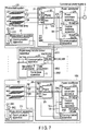
- FIG. 7 is a schematic block diagram for explaining a seventh embodiment of the photovoltaic power generation system according to the present invention.
- FIG. 8 is a schematic block diagram for explaining an eighth embodiment of the photovoltaic power generation system according to the present invention.
- FIG. 9 is a schematic block diagram for explaining a ninth embodiment of the photovoltaic power generation system according to the present invention.
- FIG. 10 is a schematic block diagram for explaining a 10th embodiment of the photovoltaic power generation system according to the present invention.
- FIG. 11 is a schematic block diagram for explaining an 11th embodiment of the photovoltaic power generation system according to the present invention.
- FIG. 12 is a schematic block diagram for explaining a 12th embodiment of the photovoltaic power generation system according to the present invention.
- FIG. 13 is a schematic block diagram for explaining a 13th embodiment of the photovoltaic power generation system according to the present invention.
- FIG. 14 is a flowchart for explaining an operation of the first embodiment of the photovoltaic power generation system according to the present invention.
- FIG. 15 is a flowchart for explaining the operation of the first embodiment of the photovoltaic power generation system according to the present invention.
- FIG. 16 is an operation explanatory view for explaining of an operation of each unit of the first embodiment in the photovoltaic power generation system according to the present invention.
- FIG. 17 is an operation explanatory view for explaining of the operation of each unit of the first embodiment in the photovoltaic power generation system according to the present invention.
- FIG. 18 is an operation explanatory view for explaining of the operation of each unit of the first embodiment in the photovoltaic power generation system according to the present invention.
- FIG. 19A is a view for explaining a display method of a display apparatus that displays an output from a curve trace apparatus in the photovoltaic power generation system according to the present invention
- FIG. 19B is a view for explaining the display method of the display apparatus that displays an output from a curve trace apparatus in the photovoltaic power generation system according to the present invention.
- FIG. 19C is a view for explaining the display method of the display apparatus that displays an output from a curve trace apparatus in the photovoltaic power generation system according to the present invention.
- FIG. 20A is a view for explaining the display method of the display apparatus that displays an output from the curve trace apparatus in the photovoltaic power generation system according to the present invention
- FIG. 20B is a view for explaining the display method of the display apparatus that displays an output from the curve trace apparatus in the photovoltaic power generation system according to the present invention
- FIG. 21 is a view for explaining the display method of the display apparatus that displays an output from the curve trace apparatus in the photovoltaic power generation system according to the present invention.
- FIG. 22A is a view for explaining the display method of the display apparatus that displays an output from the curve trace apparatus in the photovoltaic power generation system according to the present invention
- FIG. 22B is a view for explaining the display method of the display apparatus that displays an output from the curve trace apparatus in the photovoltaic power generation system according to the present invention
- FIG. 22C is a view for explaining the display method of the display apparatus that displays an output from the curve trace apparatus in the photovoltaic power generation system according to the present invention.
- FIG. 23A is a view for explaining the display method of the display apparatus that displays an output from the curve trace apparatus in the photovoltaic power generation system according to the present invention
- FIG. 23B is a view for explaining the display method of the display apparatus that displays an output from the curve trace apparatus in the photovoltaic power generation system according to the present invention.
- FIG. 24 is a view for explaining the display method of the display apparatus that displays an output from the curve trace apparatus in the photovoltaic power generation system according to the present invention.
- FIG. 1 is a schematic block diagram for explaining a first embodiment of the present invention; this embodiment comprises photovoltaic power generation systems 101 . . . 10 N and one supervisory remote control apparatus 1 , and direct-current power generated by the respective photovoltaic generation systems 101 . . . 10 n is converted into alternating-current power by respective power conditioners 21 . . . 2 N and supplied to a commercial power supply (an alternating-current power system) 5 .
- the supervisory remote control apparatus 1 supervises and controls states of the photovoltaic power generation systems 101 . . . 10 N.
- the photovoltaic power generation system 101 comprises a photovoltaic array 41 , the power conditioner 21 that converts the direct-current power generated by the photovoltaic array 41 into the alternating-current power and supplies this power to the alternating-current power system 5 , a power collection box 81 and a cable run 71 which are arranged between the photovoltaic array 41 and the power conditioner 21 , and a measurement apparatus 31 that measures power generating conditions of the photovoltaic array 41 .
- the photovoltaic power generation system 10 N comprises one photovoltaic array 4 N, the power conditioner 2 N that converts the direct-current power generated by the photovoltaic array 4 N into the alternating-current power and supplies this power to the alternating-current power system 5 , a power collection box 8 N and a cable run 7 N which are arranged between the photovoltaic array 4 N and the power conditioner 2 N, and a measurement apparatus 3 N that measures power generating conditions of the photovoltaic array 4 N.
- the photovoltaic array means one obtained by combining photovoltaic cells as a minimum unit of a photovoltaic battery to constitute each photovoltaic module (a photovoltaic panel) and connecting these photovoltaic modules in series, parallel, or series-parallel, one photovoltaic array will be referred to as one group or one unit, and a plurality of photovoltaic arrays will be referred to as groups or units.
- Communication apparatuses 12 , 212 . . . 2 N 2 , 313 . . . 3 N 3 are installed in the supervisory remote control apparatus 1 , and the power conditions 21 . . . 2 N and the measurement apparatuses 31 . . . 3 N in the respective groups, thereby providing a communication system comprising signal transmission paths 911 . . . 9 N 1 , 912 . . . 9 N 2 , and 913 . . . 9 N 3 that enable communication between the communication apparatus 12 of the supervisory remote control apparatus 1 and the communication apparatuses 313 . . . 3 N 3 of the measurement apparatuses 31 . . . 3 N and between the communication apparatus 12 of the supervisory remote control apparatus 1 and the communication apparatuses 212 . . . 2 N 2 of the respective power conditioners 21 . . . 2 N.
- the power conditioner 21 comprises a power conversion apparatus 211 , a control switching apparatus 213 , the communication apparatus 212 , a direct-current voltage detector 214 that detects a direct-current voltage as an input to the power conversion apparatus 211 and an output from the photovoltaic array 41 and supplies this direct-current voltage detection value Vdc to the control switching apparatus 213 and the communication apparatus 212 , and a direct current detector 215 that detects a direct current as an input to the power conversion apparatus 211 and an output from the photovoltaic array 41 and supplies this direct current detection value Idc to the control switching apparatus 213 and the communication apparatus 212 .
- the control switching apparatus 213 switches max power point tracking (MPPT) control for controlling in such a manner that the power conditioner 21 can receive a direct-current voltage command Vref or a direct current command Iref and a control switching command SCAN from the supervisory remote control apparatus 1 through the communication system and an output from the power conversion apparatus 211 included in the power conditioner 21 can become maximum for voltage control or current control based on the direct-current voltage command Vref or the direct current command Iref.
- MPPT power point tracking
- the power conditioner 2 N comprises a power conversion apparatus 2 N 1 , a control switching apparatus 2 N 3 , the communication apparatus 2 N 2 , a direct-current voltage detector 2 N 4 that detects a direct-current voltage as an input to the power conversion apparatus 2 N 1 and an output from the photovoltaic array 4 N and supplies this direct-current voltage detection value Vdc to the control switching apparatus 2 N 3 and the communication apparatus 2 N 2 , and a direct current detector 215 that detects a direct current as an input to the power conversion apparatus 2 N 1 and an output from the photovoltaic array 4 N and supplies this direct current detection value Idc to the control switching apparatus 2 N 3 and the communication apparatus 2 N 2 .
- the control switching apparatus 2 N 3 switches the MPPT control for controlling in such a manner that the power conditioner 2 N can receive the direct-current voltage command Vref or the direct current command Iref and the control switch command SCAN from the supervisory remote control apparatus 1 through the communication system and an output from the power conversion apparatus 2 N 1 included in the power conditioner 2 N can become maximum to voltage control or current control based on the direct-current voltage command Vref or the direct current command Iref.
- the measurement apparatuses 31 . . . 3 N have at least one (provided in accordance with each of the photovoltaic arrays 41 . . . 4 N in this example) solar radiation intensity detector and the communication apparatuses 313 . . . 3 N, the solar radiation intensity detector including actinometers 311 . . . 3 N 1 that measure solar radiation intensity as power generating conditions of the respective photovoltaic arrays 41 . . . 4 N and air temperature gauges 312 . . . 3 N 2 that detect and measure air temperatures at places where the photovoltaic arrays 41 . . . 4 N are installed.
- the supervisory remote control apparatus 1 comprises a later-described curve trace apparatus 11 and the communication apparatus 12 .
- the curve trace apparatus 11 is installed in the supervisory remote control apparatus 1 , fetches direct current detection values (I) detected by the respective direct current detectors 215 . . . 2 N 5 included in the respective power conditioners 21 . . . 2 N and direct-current voltage values (V) detected by the respective direct-current voltage detectors 214 . . . 2 N 4 included in the respective power conditioners 21 . . . 2 N, thereby traces I-V characteristic diagrams for the respective photovoltaic arrays 41 . . . 4 N, and traces the solar radiation intensity detection values and air temperature detection values detected by the measurement apparatuses 31 . . .
- the power collection boxes 81 . . . 8 N accommodate diodes that prevent outputs from the photovoltaic arrays 41 . . . 4 N from flowing back to a plurality of (three in this embodiment) photovoltaic modules constituting the respective photovoltaic arrays 41 . . . 4 N, switches used when performing maintenance and inspection of the photovoltaic power generation system, and others.
- FIG. 16 shows that I-V curve scan command data is executed based on a sampling system.
- the curve trace apparatus 11 included in the supervisory remote control apparatus 1 comprises a command data creation apparatus 111 and an I-V characteristic plot creation apparatus 112 .
- the command data creation apparatus 111 creates command data in accordance with a scan mode ON/OFF command, the direct-current voltage command Vref or the direct current command Iref, and a cycle ⁇ T, e.g., every 1 second in response to the control switching command SCAN, and thereby sets a direct-current voltage command value (a direct current command value).
- the communication apparatus 12 transmits the direct-current voltage command value or the direct current command value set by the command data creation apparatus 111 to the communication apparatus 212 of the power conditioner 21 through a signal transmission path.
- the direct-current voltage command value (the direct current command value) is supplied to the power conditioner 21 in accordance with the cycle received by the communication apparatus 212 .
- the control switching apparatus 213 of the power conditioner 21 inputs the direct-current voltage command value or the direct current command value as an external command to the power conditioner 21 in accordance with the cycle received through the communication and performs the I-V curve scan.
- the communication apparatus 212 transmits (returns) the direct-current voltage command (the direct-current voltage command) from the control switching apparatus 213 , the direct-current voltage detection value and the direct current detection value detected by the detector, and direct-current power calculated based on these values to the communication apparatus 212 , and the I-V characteristic plot creation apparatus 11 creates an I-V characteristic plot.
- FIG. 17 shows that the I-V curve scan command data is executed based on a collective system.
- the curve trace apparatus 11 included in the supervisory remote control apparatus 1 comprises the I-V characteristic plot creation apparatus 112 , it does not comprise a command data creation apparatus, and it is configured to perform output in accordance with the scan mode ON/OFF command, the direct-current voltage command value or the direct current command value, and the cycle ⁇ , e.g., 1 second.
- the power conditioner 21 comprises a setting unit 2137 so that a direct-current voltage command computational expression or a direct current command computational expression can be set.
- the control switching apparatus 213 in the power conditioner 21 performs the I-V curve scan based on the communication when the scan mode is changed to ON, inputs the voltage command, the current command, and the cycle command to the command computational expression, thereby calculating an external command based on the command computational expression.
- the thus obtained direct-current voltage command or direct current command is returned to the supervisory remote control apparatus 1 by the communication apparatus, and the I-V characteristic plot creation apparatus 11 creates an characteristic plot.
- the above-described operation of the curve trace apparatus 1 is carried out as shown in FIG. 14 or FIG. 15 , and I-V curve scan is stopped if solar radiation fluctuates during the I-V curve scan in any case.
- I-V curve scan is stopped if solar radiation fluctuates during the I-V curve scan in any case.
- FIG. 14 for example, when a scan mode command Vref_scan or Iref_scan is issued to the power conditioner 21 from the voltage command data creation apparatus 111 in FIG. 1 and FIG. 16 (S 1 ), whether solar radiation intensity measured by the actinometers 311 . . . 3 N 1 has fluctuated is judged (S 2 ), and the I-V curve scan is terminated when the solar radiation has fluctuated (S 6 ).
- the I-V curve scan is continued if the scan voltage Vref_scan or the scan current Iref_scan 11 is not equal to or larger than a set limit Vdclimit or Idc_limit, and the I-V curve scan is terminated if the same voltage or current is equal to or above a limit Vdc-limit or Idc_limit.
- FIG. 15 shows an example of moving the I-V curve scan in accordance with each group, and a step of making a selection from the power conditioners 21 . . . 2 N is added between S 1 and S 2 in FIG. 14 .
- a step of making a selection from the power conditioners 21 . . . 2 N is added between S 1 and S 2 in FIG. 14 .
- an odd number, an even number, a string converter on the photovoltaic (PV) module side, or the like is freely selected. Steps other than one described above are equal to those in FIG. 14 , and hence like reference numerals denote like parts to omit a description thereof.
- FIG. 18 illustrates operation times for executing the I-V curve scan in a day.
- a PCS operation time means a time during which the PCS operates in a day.
- An I-V curve scan periodic time means a time during which the I-V curve scan is periodically executed in the PCS operation time.
- solar radiation>set solar radiation and an I-V curve scan execution trigger the I-V curve scan execution trigger is output when solar radiation is larger than the set solar radiation in the periodic time, but the I-V curve scan execution trigger is not output when solar radiation is smaller than the set solar radiation.
- the characteristic diagram traced by the curve trace apparatus 11 since solar radiation intensity or an air temperature as measurement conditions for evaluating an output from the photovoltaic power generation system is drawn in the characteristic diagram traced by the curve trace apparatus 11 , evaluation based on comparison with a characteristic estimated value under the reference conditions (1 KW/m 2 , 25° C.) of the photovoltaic cell can be easily performed.
- I-V curves and/or P-V curves in the photovoltaic arrays 41 . . . 4 N can be managed and controlled in synchronization with each other by the supervisory remote control apparatus 1 , and evaluation based on comparison of outputs from the photovoltaic power generation systems under the same power generating conditions can be easily carried out.
- an impact diagnosis of an environment of the photovoltaic arrays 41 . . . 4 N, solar radiation based on installation conditions, an air temperature, and sun shadow can be carried out, and deterioration of the photovoltaic arrays 41 . . . 4 N or fouling due to dust or stains can be also analyzed.
- FIG. 2 is a schematic block diagram for explaining a second embodiment of the present invention, and it is different from the embodiment depicted in FIG. 1 in that one measurement apparatus 30 having an actinometer 301 and an air temperature gauge 302 is provided to a specific one of the photovoltaic arrays 41 . . . 4 N or one position other than this place, whereas each of the measurement apparatuses 31 . . . 3 N having actinometers 311 . . . 3 N 1 and the air temperature gauges 312 . . . 3 N 2 as one of the power generating conditions is provided in accordance with each of the photovoltaic arrays 41 . . . 4 N in the embodiment depicted in FIG. 1 .
- a solar radiation intensity detection value Irr obtained by actinometer 301 and an air temperature detection value Tmp obtained by the air temperature gauge 302 measured by the measurement apparatus 30 are transmitted to a curve trace apparatus 11 through a communication apparatus 303 included in the measurement apparatus 30 , a communication apparatus 12 included in a supervisory remote control apparatus 1 , and a signal transmission path connecting these apparatuses.
- FIG. 3 is a schematic block diagram for explaining a third embodiment according to the present invention, and it is different from the embodiment depicted in FIG. 1 in that power collection box apparatuses 91 . . . 9 N comprising power collection boxes 81 . . . 8 N and direct current detectors 911 , 912 . . . 91 M, . . . 9 N 1 , 9 N 2 . . . 9 NM are newly provided in place of the power collection boxes 81 . . . 8 N, and the power collection box apparatuses 91 . . . 9 N are configured as follows. That is, the direct current detectors 911 , 912 . . . 91 M, . . .
- I-V curve scan for each photovoltaic module and each photovoltaic array can be carried out by the curve trace apparatus 11 .
- FIG. 4 is a schematic block diagram for explaining a fourth embodiment of the present invention, and it is different from the embodiment depicted in FIG. 1 in that the measurement apparatuses 31 . . . 3 N are not provided and solar radiation intensity detection values and air temperature detection values measured by actinometers 311 . . . 3 N 1 and air temperature gauges 312 . . . 3 N 2 are input to a curve trace apparatus 11 through communication apparatuses 212 . . . 2 N 2 and a communication apparatus 12 .
- This embodiment can be applied to a clustered grid-connected photovoltaic system, e.g., a residential photovoltaic system.
- FIG. 5 is a schematic block diagram for explaining a fifth embodiment according to the present invention, and it is different from the embodiment depicted in FIG. 1 in that industrial cameras 3161 . . . 316 N that enable visually confirming a solar radiation environment of array or module installing positions and anemometers 3151 . . . 315 N that measure wind velocities are newly added as measurement apparatuses 31 . . . 3 N that detect power generating conditions, respectively.
- FIG. 6 is a schematic block diagram for explaining a sixth embodiment of the present invention, and it is different from the embodiment depicted in FIG. 1 in that alternating-current voltage detectors 216 . . . 2 N 6 and alternating current detectors 217 . . . 2 N 7 are newly provided on output sides of respective power conversion apparatuses 211 . . . 2 N 1 , alternating-current power arithmetic units 218 . . . 2 N 8 that calculate alternating-current power based on these alternating-current detection values are provided, and calculated values of the alternating-current power arithmetic units 218 . . . 2 N 8 are led to a curve trace apparatus 11 through communication apparatuses 212 . . .
- FIG. 7 is a schematic block diagram for explaining a seventh embodiment according to the present invention, and it is different from the embodiment depicted in FIG. 1 in that the power collection boxes 81 . . . 8 N are not provided, but new power collection box apparatuses 91 . . . 9 N are provided in power conditioners 21 . . . 2 N, and the power collection box apparatuses 91 . . . 9 N are configured as follows. That is, to detect a direct current of each module constituting the array, direct current detectors 911 , 912 , . . . 91 M . . . 9 N 1 , 9 N 2 , . . . 9 NM are provided to direct-current bus lines 711 , 712 , .
- FIG. 8 is a schematic block diagram for explaining an eighth embodiment according to the present invention, and it is different from the embodiment depicted in FIG. 1 in that the power collection boxes 81 . . . 8 N are not provided, but new power collection box apparatuses 91 . . . 9 N are provided, and the power collection box apparatuses 91 . . . 9 N are configured as follows. That is, they are provided to direct-current bus lines 71 . . . 7 N of the respective modules constituting an array and power conditioners 21 . . . 2 N, and the power collection box apparatuses 91 . . . 9 N are configured as follows. That is, to detect a direct current for each of modules 411 , 412 , . . .
- direct current detectors 911 , 912 , . . . 91 M . . . 9 N 1 , 9 N 2 , . . . 9 NM are provided to the direct-current bus lines 71 . . . 7 N connecting the respective modules to the power collection boxes 8 N, switches 811 , 812 . . . 81 M, 8 N 1 , 8 N 2 . . . and 8 NM are connected to the direct current detectors 911 , 912 , . . . 91 M . . . 9 N 1 , 9 N 2 , . . .
- a curve trace apparatus 11 of a supervisory remote control apparatus 1 is configured to enable selecting operations of the switches 811 , 812 . . . 81 M, 8 N 1 , 8 N 2 . . . 8 NM through communication apparatuses 31 . . . 3 N, and 12 .
- FIG. 9 is a schematic block diagram for explaining a ninth embodiment according to the present invention, and it is different from the embodiment shown in FIG. 1 in that the power collection boxes 81 . . . 8 N are not provided, but new power collection box apparatuses 91 . . . 9 N are provided in power conditioners 21 . . . 2 N, and the power collection box apparatuses 91 . . . 9 N are configured as follows. That is, to detect a direct current of each module constituting an array, direct current detectors 911 , 912 , . . . 91 M . . . 9 N 1 , 9 N 2 , . . . 9 NM are provided to direct-current bus lines 711 , 712 , . .
- the direct current detectors 911 , 912 , . . . 91 M . . . 9 N 1 , 9 N 2 , . . . 9 NM and the power collection boxes 81 . . . 8 N are provided in power conditioners 21 . . . 2 N, switches 811 , 812 . . . 81 M, 8 N 1 , 8 N 2 . . . 8 NM are connected to the direct current detectors 911 , 912 , . . . 91 M . . .
- a curve trace apparatus 11 of a supervisory remote control apparatus 1 is configured to enable selecting operations of the switches 811 , 812 . . . 81 M, 8 N 1 , 8 N 2 . . . 8 NM through communication apparatuses 212 . . . 2 N 2 , and 12 .
- FIG. 10 is a schematic block diagram for explaining a 10th embodiment according to the present invention, and it is different from the embodiment depicted in FIG. 1 in that the power conditioners 21 . . . 2 N provided to the direct-current bus lines 71 . . . 7 N of the power collection boxes 81 . . . 8 N and the power system (the commercial power supply) 5 in FIG. 1 are not provided, and they are provided to direct current cable runs between arrays or modules 41 ′ . . . 4 N 7 ′ and the power collection boxes 81 . . . 8 N, one measurement apparatus 30 having an actinometer 301 and an air temperature gauge 302 is arranged at a specific one of photovoltaic arrays 41 . . .
- the measurement apparatuses 31 . . . 3 N having the actinometers 311 and the air temperature gauges 312 . . . 3 N 2 as one of power generating conditions are provided in accordance with the respective photovoltaic arrays 41 . . . 4 N in the embodiment shown in FIG. 1 .
- FIG. 11 is a schematic block diagram for explaining an 11th embodiment according to the present invention, and it is different from the embodiment depicted in FIG. 1 in that the following configuration is adopted so that initial charging of smoothing capacitors 217 . . . 2 N 7 usually provided on input sides of the power conversion apparatuses 211 . . . 2 N 1 of the power conditioners 21 . . . 2 N in FIG. 1 can be carried out in synchronization. That is, switches 216 . . . 2 N 6 and 218 . . . 2 N 8 are provided on input sides and output sides of power conversion apparatuses 211 . . . 2 N 1 , and the switches 216 . . . 2 N 6 and 218 . . .
- 2 N 8 are controlled to be opened or closed by a curve trace apparatus 11 through communication apparatuses 212 . . . 2 N 2 and 12 , thereby performing the initial charging of the smoothing capacitors 217 . . . 2 N 7 in synchronization.
- FIG. 12 is a schematic block diagram for explaining a 12th embodiment according to the present invention, and it is different from the embodiment depicted in FIG. 1 in that the following configuration is adopted so that initial charging of smoothing capacitors 217 . . . 2 N 7 usually provided on input sides of the power conversion apparatuses 211 . . . 2 N 1 of the power conditioners 21 . . . 2 N in FIG. 1 can be carried out in synchronization. That is, recording apparatuses 219 . . . 2 N 9 that temporarily record detection values detected by direct-current voltage detectors 214 . . . 2 N 4 and direct current detectors 215 . . .
- FIG. 13 is a schematic block diagram for explaining a 13th embodiment according to the present invention, and it is different from the embodiment depicted in FIG. 1 in that the power collection boxes 81 . . . 8 N in FIG. 1 are not provided, but new power collection box apparatuses 91 . . . 9 N are provided in power conditioners 21 . . . 2 N, and the following configuration is adopted so that initial charging of smoothing capacitors 217 . . . 2 N 7 usually provided on input sides of power conversion apparatuses 211 . . . 2 N 1 of the power conditioners 21 . . . 2 N in FIG. 1 can be carried out in synchronization. That is, the power collection box apparatuses 91 . . . 9 N are configured as follows.
- direct current detectors 911 , 912 , . . . 91 M . . . 9 N 1 , 9 N 2 , . . . 9 NM are provided to direct current bus lines 711 , 712 , . . . 71 M . . . 7 N 1 , 7 N 2 , . . . 7 NM connecting the respective modules to the power collection boxes 81 . . . 8 N, the direct current detectors 911 , 912 , . . . 91 M . . . 9 N 1 , 9 N 2 , . . . 9 NM and the power collection boxes 81 . . .
- switches 811 , 812 . . . 81 M and 8 N 1 , 8 N 2 . . . 8 NM are connected to the direct current detectors 911 , 912 , . . . 91 M . . . 9 N 1 , 9 N 2 , . . . 9 NM in series in the power collection boxes 81 . . . 8 N, and a curve trace apparatus 11 of a supervisory remote control apparatus 1 is configured to enable selecting operations of the switches 811 , 812 . . . 81 M and 8 N 1 , 8 N 2 . . . 8 NM through communication apparatuses 212 . . . 2 N 2 , 12 .
- switches 216 . . . 2 N 6 and 218 . . . 2 N 8 are provided on input sides and output sides of the power conversion apparatuses 211 . . . 2 N 1 , and the switches 216 . . . 2 N 6 and 218 . . . 2 N 8 are controlled to be opened or closed by the curve trace apparatus 11 through the communication apparatuses 212 . . . 2 N 2 and 12 , thereby performing the initial charge of the smoothing capacitors 217 . . . 2 N 7 in synchronization.
- FIG. 19A to FIG. 21 shows a display example when the number of the photovoltaic array is one.
- FIG. 19A shows a P-V curve a and a maximum power point b obtained by the MPPT control when an ordinate represents direct-current power P and an abscissa represents a direct-current V.
- FIG. 19A shows a P-V curve a and a maximum power point b obtained by the MPPT control when an ordinate represents direct-current power P and an abscissa represents a direct-current V.
- FIG. 19B shows an I-V curve c and an amount of solar radiation d when an ordinate represents an amount of solar radiation and a direct current I and an abscissa represents a direct-current voltage V.
- FIG. 19C shows currents e 1 , e 2 , and e 3 for each of the photovoltaic modules according to, e.g., the embodiment shown in FIG. 5 when an ordinate represents a direct current I and an abscissa represents a direct-current voltage V.
- FIG. 20A is a view showing direct-current power Pdc and alternating-current power Vac in, e.g., the embodiment shown in FIG. 5 when an ordinate represents direct-current power P and an abscissa represents a direct-current voltage V.
- FIG. 20B shows a P-V curve f and a maximum power point g when an ordinate represents a direct current I and an abscissa represents a direct-current voltage V.
- FIG. 21 shows a display example showing a P-V curve h and a maximum power point i in a full direct-current voltage region obtained by the switches 811 , 812 , . . . 81 M in, e.g., the embodiment depicted in FIG. 8 when an ordinate represents direct-current power P and an abscissa represents a direct-current voltage V.
- FIG. 22A to FIG. 24 shows a display example when the number of the photovoltaic arrays is more than one.
- FIG. 22A shows a P-V curve j and a maximum power point k obtained by the MPPT control when an ordinate represents direct-current power P and an abscissa represents a direct-current voltage V.
- FIG. 22B shows an I-V curve l and an amount of solar radiation m when an ordinate represents an amount of solar radiation and a direct current I and an abscissa represents a direct-current voltage V.
- FIG. 22C shows currents n 1 , n 2 , n 3 , n 4 , n 5 , and n 6 for the respective photovoltaic modules in, e.g., the embodiment depicted in FIG. 5 when an ordinate represents a direct current I and an abscissa represents a direct-current voltage V.
- FIG. 23A is a view showing direct-current power Pdc and an alternating current Vac in, e.g., the embodiment depicted in FIG. 5 when an ordinate represents direct-current power P and an abscissa represents a direct-current voltage V.
- FIG. 23B shows a P-V curve o and maximum power points p and q when an ordinate represents a direct current I and an abscissa represents a direct-current voltage V.
- FIG. 24 shows a display example of a P-V curve r and maximum power point s and t in a full direct-current voltage region obtained by the switches 811 , 812 , . . . 81 M in, e.g., the embodiment depicted in FIG. 8 when an ordinate represents direct-current power P and an abscissa represents a direct-current voltage V.
- a photovoltaic power generation system comprising: a photovoltaic array including photovoltaic modules, the photovoltaic power generation system further comprising a control apparatus configured to display output characteristics of the photovoltaic array and power generating conditions of the photovoltaic array in synchronization.
- a photovoltaic power generation system comprising:
- a photovoltaic array a photovoltaic array
- a power conditioner which converts direct-current power generated by the photovoltaic array into desired direct-current power, further converts it into alternating-current power, and supplies it to an alternating-current power system, or converts direct-current power generated by the photovoltaic array into alternating-current power and supplies it to the alternating-current power system
- a supervisory remote control apparatus which supervises and controls a state of the alternating-current power system
- a measurement apparatus which measures power generating conditions of the photovoltaic array
- the photovoltaic power generation system further comprising:
- a communication system which has communication apparatuses installed in the supervisory remote control apparatus, the power conditioner, and the measurement apparatus, respectively, and comprises a signal transmission path which enables communication between the communication apparatus in the supervisory remote control apparatus and the communication apparatus in the measurement apparatus and between the communication apparatus in the supervisory remote control apparatus and the communication apparatus in the power conditioner;
- a control switching apparatus that switches MPPT control, by which the power conditioner receives a direct-current voltage command or a direct current command and a control switching command from the supervisory remote control apparatus through the communication system and an output from the power conversion apparatus included in the power conditioner becomes maximum, to voltage control or current control using the direct-current voltage command Vref or the direct current command Iref;
- a power generating condition detector which is installed in the measurement apparatus and detects power generating conditions of the photovoltaic array
- a direct-current voltage detector which detects a direct-current voltage that is an output from the photovoltaic array
- a direct current detector which detects a direct current that is an output from the photovoltaic array
- a curve trace apparatus which is installed in the supervisory remote control apparatus, fetches a direct current detection value (I) detected by the direct current detector and a direct-current voltage detection value (V) detected by the direct-current voltage detector, traces an I-V characteristic diagram of the photovoltaic array, and also traces power generating conditions detected by the power generating condition detection on the I-V characteristic diagram, the I-V characteristic diagram and the power generating condition detection value being traced in synchronization with transmission of the direct-current voltage command or the direct current command and the control switching command from the supervisory remote control apparatus to the control switching apparatus, and the I-V characteristic diagram and the power generating condition detection value being displayed.
- I direct current detection value
- V direct-current voltage detection value
- a photovoltaic power generation system comprising:
- a photovoltaic array a photovoltaic array
- a power conditioner which converts direct-current power generated by the photovoltaic array into desired direct-current power, further converts it into alternating-current power, and supplies it to an alternating-current power system, or converts direct-current power generated by the photovoltaic array into alternating-current power and supplies it to the alternating-current power system
- a supervisory remote control apparatus which supervises and controls a state of the alternating-current power system
- a measurement apparatus which measures power generating conditions of the photovoltaic array
- the photovoltaic power generation system further comprising:
- a communication system which has communication apparatuses installed in the supervisory remote control apparatus, the power conditioner, and the measurement apparatus, respectively, and comprises a signal transmission path which enables communication between the communication apparatus in the supervisory remote control apparatus and the communication apparatus in the measurement apparatus and between the communication apparatus in the supervisory remote control apparatus and the communication apparatus in the power conditioner;
- a control switching apparatus that switches MPPT control, by which the power conditioner receives a direct-current voltage command or a direct current command and a control switching command from the supervisory remote control apparatus through the communication system and an output from the power conversion apparatus included in the power conditioner becomes maximum, to voltage control or current control using the direct-current voltage command Vref or the direct current command Iref;
- a power generating condition detector which is installed in the measurement apparatus and detects power generating conditions of the photovoltaic array
- a direct-current voltage detector which detects a direct-current voltage that is an output from the photovoltaic array
- a direct current detector which detects a direct current that is an output from the photovoltaic array
- a curve trace apparatus which is installed in the supervisory remote control apparatus, fetches a direct current detection value (I) detected by the direct current detector and a direct-current voltage detection value (V) detected by the direct-current voltage detector in synchronization with transmission of the direct-current voltage command or the direct current command from the supervisory remote control apparatus, traces a P-V characteristic diagram from direct-current power (P) calculated based on the direct-current voltage detection value (V) and the direct current detection value (I) and the direct-current voltage detection value (V), and also traces power generating conditions detected by the power generating condition detector on the P-V characteristic diagram, the P-V characteristic diagram, the solar radiation intensity detection value, and the air temperature detection value being traced in synchronization with transmission of the direct-current voltage command or the direct current command and the control switching command from the supervisory remote control apparatus to the control switching apparatus.
- a photovoltaic power generation system comprising:
- a photovoltaic array a photovoltaic array
- a power conditioner which converts direct-current power generated by the photovoltaic array into desired direct-current power, further converts it into alternating-current power, and supplies it to an alternating-current power system, or converts direct-current power generated by the photovoltaic array into alternating-current power and supplies it to the alternating-current power system
- a supervisory remote control apparatus which supervises and controls a state of the alternating-current power system
- a measurement apparatus which measures power generating conditions of the photovoltaic array
- the photovoltaic power generation system further comprising:
- a communication system which has communication apparatuses installed in the supervisory remote control apparatus, the power conditioner, and the measurement apparatus, respectively, and comprises a signal transmission path which enables communication between the communication apparatus in the supervisory remote control apparatus and the communication apparatus in the measurement apparatus and between the communication apparatus in the supervisory remote control apparatus and the communication apparatus in the power conditioner;
- a control switching apparatus that switches MPPT control, by which the power conditioner receives a direct-current voltage command or a direct current command and a control switching command from the supervisory remote control apparatus through the communication system and an output from the power conversion apparatus included in the power conditioner becomes maximum, to voltage control or current control using the direct-current voltage command Vref or the direct current command Iref;
- a power generating condition detector which is installed in the measurement apparatus and detects power generating conditions of the photovoltaic array
- a direct-current voltage detector which detects a direct-current voltage that is an output from the photovoltaic array
- a direct current detector which detects a direct current that is an output from the photovoltaic array
- a curve trace apparatus which is installed in the supervisory remote control apparatus, fetches a direct current detection value (I) detected by the direct current detector and a direct-current voltage detection value (V) detected by the direct-current voltage detector in synchronization with transmission of the direct-current voltage command or the direct current command from the supervisory remote control apparatus, traces an I-V characteristic diagram, traces a P-V characteristic diagram from direct-current power (P) calculated based on the direct-current voltage detection value (V) and the direct current detection value (I) and the direct-current voltage detection value (V), and also traces power generating conditions detected by the power generating condition detector on the P-V characteristic diagram, the I-V characteristic diagram of the photovoltaic array, the P-V characteristic diagram of the photovoltaic array, and the power generating condition detection value being traced in synchronization with transmission of the direct-current voltage command or the direct current command and the control switching command from the supervisory remote control apparatus to the control switching apparatus.
- I direct current detection value
- V direct-current voltage detection
- a photovoltaic power generation system comprising:
- a photovoltaic array a photovoltaic array
- a power conditioner which converts direct-current power generated by the photovoltaic array into desired direct-current power, further converts it into alternating-current power, and supplies it to an alternating-current power system, or converts direct-current power generated by the photovoltaic array into alternating-current power and supplies it to the alternating-current power system
- a supervisory remote control apparatus which supervises and controls a state of the alternating-current power system
- a measurement apparatus which measures power generating conditions of the photovoltaic array
- the photovoltaic power generation system further comprising:
- a communication system which has communication apparatuses installed in the supervisory remote control apparatus, the power conditioner, and the measurement apparatus, respectively, and comprises a signal transmission path which enables communication between the communication apparatus in the supervisory remote control apparatus and the communication apparatus in the measurement apparatus and between the communication apparatus in the supervisory remote control apparatus and the communication apparatus in the power conditioner;
- a control switching apparatus that switches MPPT control, by which the power conditioner receives a direct-current voltage command or a direct current command and a control switching command from the supervisory remote control apparatus through the communication system and an output from the power conversion apparatus included in the power conditioner becomes maximum, to voltage control or current control using the direct-current voltage command Vref or the direct current command Iref;
- a power generating condition detector which is installed in the measurement apparatus and detects power generating conditions of the photovoltaic array
- a direct-current voltage detector which detects a direct-current voltage that is an output from the photovoltaic array
- a direct current detector which detects a direct current that is an output from the photovoltaic array
- an alternating-current power detector which detects alternating-current power that is an output from the power conversion apparatus
- a curve trace apparatus which is installed in the supervisory remote control apparatus, fetches a direct current detection value (I) detected by the direct current detector and a direct-current voltage detection value (V) detected by the direct-current voltage detector in synchronization with transmission of the direct-current voltage command or the direct current command from the supervisory remote control apparatus, traces an I-V characteristic diagram, traces a P-V characteristic diagram from direct-current power (P) calculated based on the direct-current voltage detection value (V) and the direct current detection value (I) and the direct-current voltage detection value (V), and also traces power generating conditions detected by the power generating condition detector and an alternating-current power detection value detected by the alternating-current power detector on the P-V characteristic diagram, the I-V characteristic diagram of the photovoltaic array, the P-V characteristic diagram of the photovoltaic array, and the power generating condition detection value being traced in synchronization with transmission of the direct-current voltage command or the direct current command and the control switching command from the supervisory remote control apparatus to the control
- a photovoltaic power generation system comprising:
- a photovoltaic array a photovoltaic array
- a power conditioner which converts direct-current power generated by the photovoltaic array into desired direct-current power, further converts it into alternating-current power, and supplies it to an alternating-current power system, or converts direct-current power generated by the photovoltaic array into alternating-current power and supplies it to the alternating-current power system
- a supervisory remote control apparatus which supervises and controls a state of the alternating-current power system
- a measurement apparatus which measures power generating conditions of the photovoltaic array
- the photovoltaic power generation system further comprising:
- a communication system which has communication apparatuses installed in the supervisory remote control apparatus, the power conditioner, and the measurement apparatus, respectively, and comprises a signal transmission path which enables communication between the communication apparatus in the supervisory remote control apparatus and the communication apparatus in the measurement apparatus and between the communication apparatus in the supervisory remote control apparatus and the communication apparatus in the power conditioner;
- a control switching apparatus that switches MPPT control, by which the power conditioner receives a direct-current voltage command or a direct current command and a control switching command from the supervisory remote control apparatus through the communication system and an output from the power conversion apparatus included in the power conditioner becomes maximum, to voltage control or current control using the direct-current voltage command Vref or the direct current command Iref;
- a power generating condition detector which is installed in the measurement apparatus and detects power generating conditions of the photovoltaic array
- a direct-current voltage detector which detects a direct-current voltage that is an output from the photovoltaic array
- a direct current detector which detects a direct current that is an output from the photovoltaic array
- a curve trace apparatus which is installed in the supervisory remote control apparatus, fetches a direct current detection value (I) detected by the direct current detector and a direct-current voltage detection value (V) detected by the direct-current voltage detector in synchronization with transmission of the direct-current voltage command or the direct current command from the supervisory remote control apparatus, traces an I-V characteristic diagram, traces a P-V characteristic diagram from direct-current power (P) calculated based on the direct-current voltage detection value (V) and the direct current detection value (I) and the direct-current voltage detection value (V), and also traces power generating conditions detected by the power generating condition detector and an alternating-current power detection value detected by an alternating-current power detector on the P-V characteristic diagram, the I-V characteristic diagram of the photovoltaic array, the P-V characteristic diagram of the photovoltaic array, and the power generating condition detection value being traced in synchronization with transmission of the direct-current voltage command or the direct current command and the control switching command from the supervisory remote control apparatus to the control
- a photovoltaic power generation system wherein the photovoltaic array is divided into photovoltaic modules, and a direct current smoothing capacitor is provided on an input side of a power conversion apparatus included in the power conditioner, and
- a switch is provided to a cable run connected with each photovoltaic module to enable selection of one of the photovoltaic modules, and a cable run switch which enables performing initial charging of the smoothing capacitor simultaneously with a trace operation of the curve trace apparatus is provided on an input side of the direct current smoothing capacitor.
- a photovoltaic power generation system comprising:
- the photovoltaic power generation system further comprising a control apparatus configured to perform display control of each curve trace apparatus in synchronization.
- the communication system comprising the communication apparatus and the signal transmission path includes one of a wire communication system, a wireless communication system, and a communication system having a combination of wire communication and wireless communication.
- the present invention can be applied to not only the large-scale, e.g., a megawatt-class photovoltaic power generation system or the clustered grid-connected photovoltaic power generation system but also a verification experiment system that evaluates the photovoltaic power generation system.
Landscapes
- Engineering & Computer Science (AREA)
- Electromagnetism (AREA)
- Sustainable Development (AREA)
- Sustainable Energy (AREA)
- Power Engineering (AREA)
- Physics & Mathematics (AREA)
- Life Sciences & Earth Sciences (AREA)
- General Physics & Mathematics (AREA)
- Radar, Positioning & Navigation (AREA)
- Automation & Control Theory (AREA)
- Photovoltaic Devices (AREA)
- Remote Monitoring And Control Of Power-Distribution Networks (AREA)
- Supply And Distribution Of Alternating Current (AREA)
- Control Of Electrical Variables (AREA)
Applications Claiming Priority (1)
| Application Number | Priority Date | Filing Date | Title |
|---|---|---|---|
| PCT/JP2010/053164 WO2011104882A1 (ja) | 2010-02-26 | 2010-02-26 | 太陽光発電システム |
Related Parent Applications (1)
| Application Number | Title | Priority Date | Filing Date |
|---|---|---|---|
| PCT/JP2010/053164 Continuation WO2011104882A1 (ja) | 2010-02-26 | 2010-02-26 | 太陽光発電システム |
Publications (2)
| Publication Number | Publication Date |
|---|---|
| US20130054037A1 US20130054037A1 (en) | 2013-02-28 |
| US9141122B2 true US9141122B2 (en) | 2015-09-22 |
Family
ID=44506325
Family Applications (1)
| Application Number | Title | Priority Date | Filing Date |
|---|---|---|---|
| US13/594,020 Active 2031-10-15 US9141122B2 (en) | 2010-02-26 | 2012-08-24 | Photovoltaic power generation system |
Country Status (6)
| Country | Link |
|---|---|
| US (1) | US9141122B2 (ja) |
| EP (1) | EP2541364B1 (ja) |
| JP (1) | JP5531260B2 (ja) |
| CN (1) | CN102770822B (ja) |
| ES (1) | ES2853174T3 (ja) |
| WO (1) | WO2011104882A1 (ja) |
Cited By (2)
| Publication number | Priority date | Publication date | Assignee | Title |
|---|---|---|---|---|
| US9979199B2 (en) | 2012-10-11 | 2018-05-22 | Windstrip Llc | Multiple input single output hybrid power system |
| TWI765821B (zh) * | 2021-09-13 | 2022-05-21 | 崑山科技大學 | 陰影模式太陽能系統的最大發電功率預測方法 |
Families Citing this family (19)
| Publication number | Priority date | Publication date | Assignee | Title |
|---|---|---|---|---|
| IL215097A (en) * | 2010-09-12 | 2017-05-29 | Rabinovici Raul | Camera controlled solar cell array |
| JP2012085238A (ja) * | 2010-10-14 | 2012-04-26 | Ricoh Co Ltd | 画像処理装置、画像処理装置の電力制御方法、画像処理装置の電力制御プログラム及び記録媒体 |
| JP2013097596A (ja) * | 2011-11-01 | 2013-05-20 | Sony Corp | 太陽電池システム、電子機器および建築物 |
| JP2013187496A (ja) * | 2012-03-09 | 2013-09-19 | Panasonic Corp | 発電制御装置、発電制御システム、および発電制御方法 |
| JP6007526B2 (ja) * | 2012-03-13 | 2016-10-12 | オムロン株式会社 | 充電電力制御装置、充電電力制御方法、プログラム、および太陽光発電システム |
| JP5646112B2 (ja) * | 2012-03-26 | 2014-12-24 | 三菱電機株式会社 | 電力変換装置 |
| JP6106942B2 (ja) * | 2012-04-05 | 2017-04-05 | 株式会社戸上電機製作所 | 発電出力測定装置 |
| TW201349731A (zh) * | 2012-05-30 | 2013-12-01 | Delta Electronics Inc | 具有發電模組之太陽能發電系統及其輸出電能控制方法 |
| EP3059653B1 (en) * | 2013-10-15 | 2020-11-25 | Toshiba Mitsubishi-Electric Industrial Systems Corporation | Power conversion device and method for controlling same |
| JP6175514B2 (ja) * | 2013-12-16 | 2017-08-02 | 京セラ株式会社 | 電力制御装置、機器制御装置、及び方法 |
| JP6255251B2 (ja) * | 2014-01-22 | 2017-12-27 | 株式会社日立製作所 | 太陽光発電装置の出力推定方法および装置並びにこれを用いた電力系統監視装置 |
| US10003300B2 (en) * | 2015-10-09 | 2018-06-19 | Sunpower Corporation | Photovoltaic management and module-level power electronics |
| US10439401B2 (en) * | 2015-11-23 | 2019-10-08 | Doosan Gridtech, Inc. | Managing the outflow of a solar inverter |
| JP6410962B2 (ja) * | 2015-11-26 | 2018-10-24 | 三菱電機株式会社 | 配電系統管理装置、計測装置、配電系統管理システムおよび発電量推定方法 |
| US10847974B2 (en) * | 2016-05-24 | 2020-11-24 | Mitsubishi Electric Corporation | Device and method for estimating a voltage distribution along a power distribution line in a high-voltage system |
| CN106712716B (zh) * | 2017-02-10 | 2019-02-01 | 阳光电源股份有限公司 | 一种光伏组件的iv曲线扫描方法及优化器 |
| JP2019054587A (ja) * | 2017-09-13 | 2019-04-04 | 東芝三菱電機産業システム株式会社 | パワーコンディショナシステムおよび太陽光発電システム |
| CN107800384A (zh) * | 2017-10-19 | 2018-03-13 | 中国电子科技集团公司第四十研究所 | 一种用于光伏组件iv特性对比测试的并发控制方法 |
| JP2019161886A (ja) * | 2018-03-14 | 2019-09-19 | オムロン株式会社 | I−vカーブ測定装置 |
Citations (23)
| Publication number | Priority date | Publication date | Assignee | Title |
|---|---|---|---|---|
| US4924175A (en) * | 1988-02-29 | 1990-05-08 | Clinton James R | Apparatus for displaying analog signatures of an electronic component |
| JPH1063358A (ja) | 1996-08-13 | 1998-03-06 | Sharp Corp | 連系形太陽光発電装置 |
| JPH10326902A (ja) | 1997-05-26 | 1998-12-08 | Canon Inc | 太陽電池出力特性の測定装置及びその測定方法 |
| JP2000232736A (ja) | 1999-02-12 | 2000-08-22 | Tdk Corp | 連系分散型発電システム |
| US6111767A (en) * | 1998-06-22 | 2000-08-29 | Heliotronics, Inc. | Inverter integrated instrumentation having a current-voltage curve tracer |
| US6239997B1 (en) * | 2000-09-01 | 2001-05-29 | Ford Motor Company | System for connecting and synchronizing a supplemental power source to a power grid |
| JP2002340628A (ja) | 2001-05-18 | 2002-11-27 | Canon Inc | 測定システム |
| JP2003133569A (ja) | 2001-10-30 | 2003-05-09 | Atsushi Iga | フィールドにおける太陽電池の出力評価方法・装置 |
| JP2004077309A (ja) | 2002-08-20 | 2004-03-11 | Atsushi Iga | 太陽電池の出力評価方法,出力評価プログラムを記録したコンピュータ読み取り可能なデータ記録媒体および出力評価装置 |
| US20050017697A1 (en) * | 2002-09-19 | 2005-01-27 | Alcatel | Conditioning circuit for a power supply at the maximum power point, a solar generator, and a conditioning method |
| US20050172995A1 (en) * | 2002-05-17 | 2005-08-11 | Rudiger Rohrig | Circuit arrangement for a photovoltaic system |
| JP2005340464A (ja) | 2004-05-26 | 2005-12-08 | Sharp Corp | 太陽電池アレイ診断装置およびそれを用いた太陽光発電システム |
| CN1808164A (zh) | 2005-01-18 | 2006-07-26 | 欧姆龙株式会社 | 内设曲线描绘器的功率调节器及其描绘器的曲线评价方法 |
| US7193872B2 (en) * | 2005-01-28 | 2007-03-20 | Kasemsan Siri | Solar array inverter with maximum power tracking |
| US20080238195A1 (en) * | 2007-03-27 | 2008-10-02 | Shaver Argil E | Distributed maximum power point tracking system, structure and process |
| US20080290252A1 (en) * | 2007-05-23 | 2008-11-27 | Sma Technologie Ag | Power matching method |
| US7538451B2 (en) * | 2004-06-15 | 2009-05-26 | Sony Corporation | Power supply system and electronic device |
| US20090145480A1 (en) * | 2007-12-05 | 2009-06-11 | Meir Adest | Photovoltaic system power tracking method |
| JP2009148014A (ja) | 2007-12-12 | 2009-07-02 | Meidensha Corp | 太陽光発電システムの連系方法 |
| US20100001587A1 (en) * | 2008-07-01 | 2010-01-07 | Satcon Technology Corporation | Photovoltaic dc/dc micro-converter |
| US20100138063A1 (en) * | 2009-08-28 | 2010-06-03 | General Electric Company | Systems and methods for interfacing renewable power sources to a power grid |
| US7986539B2 (en) * | 2007-09-26 | 2011-07-26 | Enphase Energy, Inc. | Method and apparatus for maximum power point tracking in power conversion based on dual feedback loops and power ripples |
| US20110210611A1 (en) * | 2008-10-10 | 2011-09-01 | Ampt, Llc | Novel Solar Power Circuits |
Family Cites Families (3)
| Publication number | Priority date | Publication date | Assignee | Title |
|---|---|---|---|---|
| JP2006101591A (ja) * | 2004-09-28 | 2006-04-13 | Hitachi Cable Ltd | 太陽光発電装置 |
| US8204709B2 (en) * | 2005-01-18 | 2012-06-19 | Solar Sentry Corporation | System and method for monitoring photovoltaic power generation systems |
| JP5162737B2 (ja) * | 2006-05-17 | 2013-03-13 | 英弘精機株式会社 | 太陽電池の特性評価装置 |
-
2010
- 2010-02-26 CN CN201080064675.2A patent/CN102770822B/zh active Active
- 2010-02-26 EP EP10846546.9A patent/EP2541364B1/en active Active
- 2010-02-26 ES ES10846546T patent/ES2853174T3/es active Active
- 2010-02-26 JP JP2012501610A patent/JP5531260B2/ja active Active
- 2010-02-26 WO PCT/JP2010/053164 patent/WO2011104882A1/ja active Application Filing
-
2012
- 2012-08-24 US US13/594,020 patent/US9141122B2/en active Active
Patent Citations (26)
| Publication number | Priority date | Publication date | Assignee | Title |
|---|---|---|---|---|
| US4924175A (en) * | 1988-02-29 | 1990-05-08 | Clinton James R | Apparatus for displaying analog signatures of an electronic component |
| JPH1063358A (ja) | 1996-08-13 | 1998-03-06 | Sharp Corp | 連系形太陽光発電装置 |
| JPH10326902A (ja) | 1997-05-26 | 1998-12-08 | Canon Inc | 太陽電池出力特性の測定装置及びその測定方法 |
| US6111767A (en) * | 1998-06-22 | 2000-08-29 | Heliotronics, Inc. | Inverter integrated instrumentation having a current-voltage curve tracer |
| JP2000232736A (ja) | 1999-02-12 | 2000-08-22 | Tdk Corp | 連系分散型発電システム |
| US6239997B1 (en) * | 2000-09-01 | 2001-05-29 | Ford Motor Company | System for connecting and synchronizing a supplemental power source to a power grid |
| JP2002340628A (ja) | 2001-05-18 | 2002-11-27 | Canon Inc | 測定システム |
| JP2003133569A (ja) | 2001-10-30 | 2003-05-09 | Atsushi Iga | フィールドにおける太陽電池の出力評価方法・装置 |
| US20050172995A1 (en) * | 2002-05-17 | 2005-08-11 | Rudiger Rohrig | Circuit arrangement for a photovoltaic system |
| JP2005528071A (ja) | 2002-05-17 | 2005-09-15 | レーリヒ リューディガー | 光起電力装置用回路装置 |
| JP2004077309A (ja) | 2002-08-20 | 2004-03-11 | Atsushi Iga | 太陽電池の出力評価方法,出力評価プログラムを記録したコンピュータ読み取り可能なデータ記録媒体および出力評価装置 |
| US20050017697A1 (en) * | 2002-09-19 | 2005-01-27 | Alcatel | Conditioning circuit for a power supply at the maximum power point, a solar generator, and a conditioning method |
| JP2005340464A (ja) | 2004-05-26 | 2005-12-08 | Sharp Corp | 太陽電池アレイ診断装置およびそれを用いた太陽光発電システム |
| US7538451B2 (en) * | 2004-06-15 | 2009-05-26 | Sony Corporation | Power supply system and electronic device |
| JP2006201827A (ja) | 2005-01-18 | 2006-08-03 | Omron Corp | カーブトレーサを内蔵したパワーコンディショナおよびカーブトレーサのカーブ評価方法 |
| EP1691246A2 (en) * | 2005-01-18 | 2006-08-16 | Omron Corporation | Power conditioner comprising curve tracer and curve evaluating method for curve tracer |
| CN1808164A (zh) | 2005-01-18 | 2006-07-26 | 欧姆龙株式会社 | 内设曲线描绘器的功率调节器及其描绘器的曲线评价方法 |
| US7193872B2 (en) * | 2005-01-28 | 2007-03-20 | Kasemsan Siri | Solar array inverter with maximum power tracking |
| US20080238195A1 (en) * | 2007-03-27 | 2008-10-02 | Shaver Argil E | Distributed maximum power point tracking system, structure and process |
| US20080290252A1 (en) * | 2007-05-23 | 2008-11-27 | Sma Technologie Ag | Power matching method |
| US7986539B2 (en) * | 2007-09-26 | 2011-07-26 | Enphase Energy, Inc. | Method and apparatus for maximum power point tracking in power conversion based on dual feedback loops and power ripples |
| US20090145480A1 (en) * | 2007-12-05 | 2009-06-11 | Meir Adest | Photovoltaic system power tracking method |
| JP2009148014A (ja) | 2007-12-12 | 2009-07-02 | Meidensha Corp | 太陽光発電システムの連系方法 |
| US20100001587A1 (en) * | 2008-07-01 | 2010-01-07 | Satcon Technology Corporation | Photovoltaic dc/dc micro-converter |
| US20110210611A1 (en) * | 2008-10-10 | 2011-09-01 | Ampt, Llc | Novel Solar Power Circuits |
| US20100138063A1 (en) * | 2009-08-28 | 2010-06-03 | General Electric Company | Systems and methods for interfacing renewable power sources to a power grid |
Non-Patent Citations (4)
| Title |
|---|
| English-language translation of International Preliminary Report on Patentability from the Japanese Patent Office For International Application No. PCT/JP2010/053164, mailing date Sep. 27, 2012. |
| English-language translation of International Search Report from the Japanese Patent Office for International Application No. PCT/JP2010/053164, mailing date May 18, 2010. |
| First Office Action from the Japan Patent Office, dated Oct. 14, 2014, for counterpart Japanese Patent Application No. 2014-004214, and English translation thereof (7 pages total). |
| Notification of the First Office Action from the State Intellectual Property Office of the People's Republic of China mailed Nov. 18, 2013, for counterpart Chinese Patent Application No. 201080064675.2, and English translation thereof (18 pages total). |
Cited By (2)
| Publication number | Priority date | Publication date | Assignee | Title |
|---|---|---|---|---|
| US9979199B2 (en) | 2012-10-11 | 2018-05-22 | Windstrip Llc | Multiple input single output hybrid power system |
| TWI765821B (zh) * | 2021-09-13 | 2022-05-21 | 崑山科技大學 | 陰影模式太陽能系統的最大發電功率預測方法 |
Also Published As
| Publication number | Publication date |
|---|---|
| US20130054037A1 (en) | 2013-02-28 |
| ES2853174T3 (es) | 2021-09-15 |
| CN102770822A (zh) | 2012-11-07 |
| JPWO2011104882A1 (ja) | 2013-06-17 |
| JP5531260B2 (ja) | 2014-06-25 |
| EP2541364A4 (en) | 2017-04-19 |
| EP2541364A1 (en) | 2013-01-02 |
| EP2541364B1 (en) | 2020-12-30 |
| WO2011104882A1 (ja) | 2011-09-01 |
| CN102770822B (zh) | 2015-03-04 |
Similar Documents
| Publication | Publication Date | Title |
|---|---|---|
| US9141122B2 (en) | Photovoltaic power generation system | |
| US8446043B1 (en) | Photovoltaic array systems, methods, and devices and improved diagnostics and monitoring | |
| JP5557820B2 (ja) | 太陽光発電設備 | |
| KR20190007250A (ko) | 현장 고장 진단이 가능한 이동형 태양광 발전설비 고장 진단시스템 | |
| KR20180072244A (ko) | 태양광 발전시스템의 고장진단 제어시스템 및 그 고장진단 제어방법 | |
| JP5713513B2 (ja) | 太陽光発電システム | |
| KR101669847B1 (ko) | 태양 광 발전모듈의 원격 진단시스템 | |
| US20210067091A1 (en) | Server | |
| KR102068014B1 (ko) | 이기종 채널 통신용 모니터링 시스템 | |
| JP2019216547A (ja) | 電力制御装置、太陽光発電システム、太陽光発電設備の不具合診断方法 | |
| CN104143956B (zh) | 太阳能发电系统 | |
| JP5879079B2 (ja) | 太陽光発電装置 | |
| KR101642681B1 (ko) | 센서의 선택적 제어를 이용하는 태양광발전 진단 시스템 | |
| WO2019187524A1 (ja) | 発電部再配置演算装置および演算処理方法 | |
| KR101664954B1 (ko) | 센싱 데이터를 줄인 태양광 발전 진단장치 | |
| JP5881759B2 (ja) | 太陽光発電システムにおける性能検査装置及びプログラム | |
| KR101113047B1 (ko) | 멀티존 싱글 인버터 태양광 발전 시스템 | |
| TW201724731A (zh) | 太陽光電模組陣列之最佳化線上即時故障檢測器及其故障檢測方法 | |
| KR101642682B1 (ko) | 단계별 태양광 발전 진단장치 | |
| Taghezouit et al. | Model-based fault detection in photovoltaic systems: A comprehensive review and avenues for enhancement | |
| JP2017103920A (ja) | 発電データ収集システム及び太陽光発電装置 | |
| Sathwara et al. | Sanjaya: An Internet of Things-Based Wireless Performance Testing of Photovoltaic Module | |
| CN102244393B (zh) | 用于光伏电站功率曲线测量和健康状况监测的系统和方法 | |
| JP2022025221A (ja) | 電池診断装置、電池診断方法 | |
| CN102244393A (zh) | 用于光伏电站功率曲线测量和健康状况监测的系统和方法 |
Legal Events
| Date | Code | Title | Description |
|---|---|---|---|
| AS | Assignment |
Owner name: NATIONAL INSTITUTE OF ADVANCED INDUSTRIAL SCIENCE Free format text: ASSIGNMENT OF ASSIGNORS INTEREST;ASSIGNORS:IKAWA, EIICHI;FUJIWARA, NAOKI;OOZEKI, TAKASHI;AND OTHERS;REEL/FRAME:029269/0646 Effective date: 20121102 Owner name: TOSHIBA MITSUBISHI-ELECTRIC INDUSTRIAL SYSTEMS COR Free format text: ASSIGNMENT OF ASSIGNORS INTEREST;ASSIGNORS:IKAWA, EIICHI;FUJIWARA, NAOKI;OOZEKI, TAKASHI;AND OTHERS;REEL/FRAME:029269/0646 Effective date: 20121102 |
|
| AS | Assignment |
Owner name: TOSHIBA MITSUBISHI-ELECTRIC INDUSTRIAL SYSTEMS COR Free format text: CHANGE OF ADDRESS OF ASSIGNEE;ASSIGNOR:TOSHIBA MITSUBISHI-ELECTRIC INDUSTRIAL SYSTEMS CORPORATION;REEL/FRAME:036208/0416 Effective date: 20140402 |
|
| STCF | Information on status: patent grant |
Free format text: PATENTED CASE |
|
| CC | Certificate of correction | ||
| MAFP | Maintenance fee payment |
Free format text: PAYMENT OF MAINTENANCE FEE, 4TH YEAR, LARGE ENTITY (ORIGINAL EVENT CODE: M1551); ENTITY STATUS OF PATENT OWNER: LARGE ENTITY Year of fee payment: 4 |
|
| MAFP | Maintenance fee payment |
Free format text: PAYMENT OF MAINTENANCE FEE, 8TH YEAR, LARGE ENTITY (ORIGINAL EVENT CODE: M1552); ENTITY STATUS OF PATENT OWNER: LARGE ENTITY Year of fee payment: 8 |
|
| AS | Assignment |
Owner name: TMEIC CORPORATION, JAPAN Free format text: CHANGE OF NAME;ASSIGNOR:TOSHIBA MITSUBISHI-ELECTRIC INDUSTRIAL SYSTEMS CORPORATION;REEL/FRAME:067244/0359 Effective date: 20240401 |