WO2011102472A1 - 電池状態推定装置および電池状態推定方法 - Google Patents
電池状態推定装置および電池状態推定方法 Download PDFInfo
- Publication number
- WO2011102472A1 WO2011102472A1 PCT/JP2011/053534 JP2011053534W WO2011102472A1 WO 2011102472 A1 WO2011102472 A1 WO 2011102472A1 JP 2011053534 W JP2011053534 W JP 2011053534W WO 2011102472 A1 WO2011102472 A1 WO 2011102472A1
- Authority
- WO
- WIPO (PCT)
- Prior art keywords
- voltage
- battery
- value
- measurement value
- secondary battery
- Prior art date
Links
Images
Classifications
-
- H—ELECTRICITY
- H01—ELECTRIC ELEMENTS
- H01M—PROCESSES OR MEANS, e.g. BATTERIES, FOR THE DIRECT CONVERSION OF CHEMICAL ENERGY INTO ELECTRICAL ENERGY
- H01M10/00—Secondary cells; Manufacture thereof
- H01M10/42—Methods or arrangements for servicing or maintenance of secondary cells or secondary half-cells
- H01M10/48—Accumulators combined with arrangements for measuring, testing or indicating the condition of cells, e.g. the level or density of the electrolyte
- H01M10/482—Accumulators combined with arrangements for measuring, testing or indicating the condition of cells, e.g. the level or density of the electrolyte for several batteries or cells simultaneously or sequentially
-
- G—PHYSICS
- G01—MEASURING; TESTING
- G01R—MEASURING ELECTRIC VARIABLES; MEASURING MAGNETIC VARIABLES
- G01R31/00—Arrangements for testing electric properties; Arrangements for locating electric faults; Arrangements for electrical testing characterised by what is being tested not provided for elsewhere
- G01R31/36—Arrangements for testing, measuring or monitoring the electrical condition of accumulators or electric batteries, e.g. capacity or state of charge [SoC]
- G01R31/382—Arrangements for monitoring battery or accumulator variables, e.g. SoC
- G01R31/3842—Arrangements for monitoring battery or accumulator variables, e.g. SoC combining voltage and current measurements
-
- G—PHYSICS
- G01—MEASURING; TESTING
- G01R—MEASURING ELECTRIC VARIABLES; MEASURING MAGNETIC VARIABLES
- G01R31/00—Arrangements for testing electric properties; Arrangements for locating electric faults; Arrangements for electrical testing characterised by what is being tested not provided for elsewhere
- G01R31/36—Arrangements for testing, measuring or monitoring the electrical condition of accumulators or electric batteries, e.g. capacity or state of charge [SoC]
- G01R31/367—Software therefor, e.g. for battery testing using modelling or look-up tables
-
- H—ELECTRICITY
- H01—ELECTRIC ELEMENTS
- H01M—PROCESSES OR MEANS, e.g. BATTERIES, FOR THE DIRECT CONVERSION OF CHEMICAL ENERGY INTO ELECTRICAL ENERGY
- H01M10/00—Secondary cells; Manufacture thereof
- H01M10/05—Accumulators with non-aqueous electrolyte
- H01M10/052—Li-accumulators
-
- Y—GENERAL TAGGING OF NEW TECHNOLOGICAL DEVELOPMENTS; GENERAL TAGGING OF CROSS-SECTIONAL TECHNOLOGIES SPANNING OVER SEVERAL SECTIONS OF THE IPC; TECHNICAL SUBJECTS COVERED BY FORMER USPC CROSS-REFERENCE ART COLLECTIONS [XRACs] AND DIGESTS
- Y02—TECHNOLOGIES OR APPLICATIONS FOR MITIGATION OR ADAPTATION AGAINST CLIMATE CHANGE
- Y02E—REDUCTION OF GREENHOUSE GAS [GHG] EMISSIONS, RELATED TO ENERGY GENERATION, TRANSMISSION OR DISTRIBUTION
- Y02E60/00—Enabling technologies; Technologies with a potential or indirect contribution to GHG emissions mitigation
- Y02E60/10—Energy storage using batteries
Definitions
- the present invention relates to a battery state estimation device and a battery state estimation method for estimating a state inside a secondary battery.
- Japanese Patent Laid-Open No. 2003-185719 discloses a control device for a secondary battery as follows. That is, the secondary battery control device defines a predetermined battery model, and converts the measured values of the current and terminal voltage of the secondary battery into state quantities using a state variable filter based on the battery model. The secondary battery control device uses this to estimate the terminal voltage of the secondary battery based on the battery model. Then, the secondary battery control device identifies the parameters of the secondary battery so that the difference between the measured voltage value and the terminal voltage estimated based on the battery model converges to zero.
- Japanese Patent Laid-Open No. 2003-185719 a part of the measured value of the secondary battery current and the measured value of the terminal voltage is used for the terminal voltage estimation calculation without being filtered by the state variable filter. It is done.
- the measured value of the current of the secondary battery and the measured value of the terminal voltage are measured by an ammeter or a voltmeter, they usually include observation noise.
- Japanese Patent Laid-Open No. 2003-185719 has a problem that the identification accuracy of the parameters of the secondary battery becomes insufficient due to the influence of the observation noise.
- the problem to be solved by the present invention is to provide a battery state estimation device and a battery state estimation method capable of identifying a parameter of a secondary battery with high accuracy.
- an aspect of the present invention detects a current and a terminal voltage of a secondary battery, and uses a measured value of the detected current and a terminal voltage to make a terminal of the secondary battery based on a predetermined battery model.
- the measured terminal voltage and the estimated terminal voltage are each filtered using a low-pass filter having the same high-frequency cutoff characteristics, and the filtered terminal voltage The measured value and the estimated terminal voltage are used.
- the measured value of the terminal voltage and the estimated value of the terminal voltage are each subjected to the filtering process by the low-pass filter having the same high-frequency cutoff characteristic, The measured terminal voltage and the estimated terminal voltage are used. Thereby, the influence of the observation noise contained in the measured values of current and terminal voltage can be effectively removed, and as a result, the parameters of the secondary battery can be identified with high accuracy.
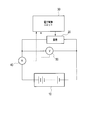
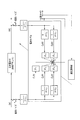
- FIG. 1 is a diagram illustrating a configuration of a control system for a secondary battery according to the present embodiment.
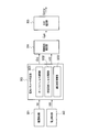
- FIG. 2 is a functional block diagram of the electronic control unit 30 according to the present embodiment.
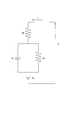
- FIG. 3 is a diagram showing an equivalent circuit model showing a battery model of the secondary battery.
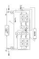
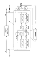
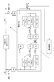
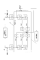
- FIG. 4 is a configuration diagram of the adaptive identification system according to the first embodiment.
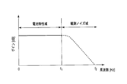
- FIG. 5 is a diagram illustrating frequency band characteristics of the current measurement value I (k), the voltage measurement value V (k), and the voltage estimation value V ⁇ (k).
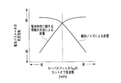
- FIG. 6 is a correlation diagram showing the relationship between the cut-off frequency of the low-pass filter G lpf , the lack of information necessary for obtaining battery characteristics, and the effect of observation noise on battery parameter identification performance.
- FIG. 1 is a diagram illustrating a configuration of a control system for a secondary battery according to the present embodiment.
- FIG. 2 is a functional block diagram of the electronic control unit 30 according to the present embodiment.
- FIG. 3 is a
- FIG. 7 is a configuration diagram of the adaptive identification system corresponding to the equivalent conversion of FIG.
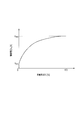
- FIG. 8 is a diagram illustrating an example of an open circuit voltage-charge rate characteristic of the secondary battery.
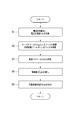
- FIG. 9 is a flowchart showing the estimation process of the battery parameters and the charging rate in the present embodiment.
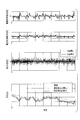
- FIG. 10 is a diagram illustrating a simulation result of the charging rate estimation process according to the first embodiment.
- FIG. 11 is a configuration diagram of an adaptive identification system according to the second embodiment.
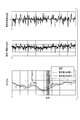
- FIG. 12 is a diagram illustrating a simulation result of the charging rate estimation process in the second embodiment.
- FIG. 13 is an example of a configuration diagram of an adaptive identification system according to the third embodiment.
- FIG. 14 is another example of a configuration diagram of the adaptive identification system according to the third embodiment.
- the control system shown in FIG. 1 is applied to the present invention in a system that drives a load such as a motor with a secondary battery or charges a secondary battery with electric power generated by motor regeneration or power generated by an alternator using an engine as a power source.
- a load such as a motor with a secondary battery or charges a secondary battery with electric power generated by motor regeneration or power generated by an alternator using an engine as a power source.
- This is an example in which such a secondary battery control device is applied.
- the secondary battery 10 is formed by connecting a plurality of unit batteries in series.
- Examples of the unit battery constituting the secondary battery 10 include a lithium secondary battery such as a lithium ion secondary battery.
- An example of the load 20 is a motor.
- the current sensor 40 is a sensor that detects a charge / discharge current flowing through the secondary battery 10. A signal detected by the current sensor 40 is sent to the electronic control unit 30.
- the voltage sensor 50 is a sensor that detects the terminal voltage of the secondary battery 10. A signal detected by the voltage sensor 50 is sent to the electronic control unit 30.
- the electronic control unit 30 is a control unit for controlling the secondary battery 10 and includes a CPU that calculates a program, a microcomputer that includes a ROM and RAM that stores programs and calculation results, an electronic circuit, and the like. .
- the electronic control unit 30 includes a current detection unit 301, a voltage detection unit 302, a battery parameter estimation unit 303, an open circuit voltage estimation unit 304, and an SOC estimation unit 305.
- the battery parameter estimation unit 303 includes a low-pass filter calculation unit 3031, a state variable filter calculation unit 3032, and an adaptive identification calculation unit 3033.
- the current detection unit 301 acquires a signal from the ammeter 40 at a predetermined cycle, and detects a charge / discharge current flowing through the secondary battery 10 based on the signal from the ammeter 40, thereby measuring a current measurement value I (k). To get.
- the current detection unit 301 sends the acquired current measurement value I (k) to the battery parameter estimation unit 303.
- the voltage detection unit 302 acquires a signal from the voltmeter 50 at a predetermined cycle, and acquires a voltage measurement value V (k) by detecting a terminal voltage of the secondary battery 10 based on the signal from the voltmeter 50. To do.
- the voltage detection unit 302 sends the acquired current measurement value V (k) to the battery parameter estimation unit 303.
- the battery parameter estimation unit 303 defines a battery model of the secondary battery 10, and uses the current measurement value I (k) detected by the current detection unit 301 and the voltage measurement value V (k) detected by the voltage detection unit 302.
- the battery parameters ⁇ ⁇ (k) of the battery model of the secondary battery 10 are collectively estimated by adaptive digital filter calculation.
- ⁇ attached to the right shoulder in ⁇ ⁇ (k) indicates that the value is an estimated value.
- ⁇ which is an estimated value, is directly above “ ⁇ ” of ⁇ (k), directly above “V” of V0 (k), and “S” of SOC (k). As shown in the following formula (1), this is synonymous with ⁇ ⁇ (k), V 0 ⁇ (k), and SOC ⁇ (k). The same applies to V ⁇ (k) below.
- FIG. 3 is an equivalent circuit model showing a battery model of the secondary battery 10, and the equivalent circuit model shown in FIG. 3 is expressed by the following equation (2).
- the model input is current I [A] (positive value is charging, negative value is discharging)
- model output is terminal voltage V [V]
- R 1 [ ⁇ ] is charge transfer resistance
- C 1 [F] is an electric double layer capacitance
- V 0 [V] is an open circuit voltage.
- s is a differential operator.
- the battery model according to the present embodiment is a reduction model (primary) in which the positive electrode and the negative electrode are not particularly separated, but it is possible to show the actual charge / discharge characteristics of the battery relatively accurately.
- a configuration in which the order of the battery model is first will be described as an example.
- the battery parameter estimation part 303 estimates the battery parameter (phi) ⁇ (k) of the battery model shown in FIG. 3 by an adaptive digital filter from the battery model shown by said Formula (4).
- a method for estimating the battery parameter ⁇ ⁇ (k) by the battery parameter estimation unit 303 will be described.
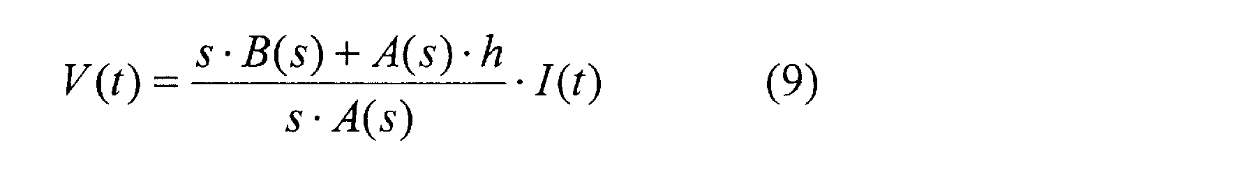
- the open circuit voltage V 0 (t) is obtained by integrating a current I (t) multiplied by a variable parameter h from an initial state.
- the open circuit voltage V 0 (t) can be expressed by the following formula (5).
- a (s) This corresponds to the order of B (s) being the primary.
- a (s) and B (s) are polynomial functions of s, and A (s) and B (s) have the same order.
- I i and b 0i are parameters including unknown parameters (T 1 , T 2 , K, h).
- f Vi and f Ii are converted state quantities obtained by filtering I (k) and V (k), which are values measurable by the ammeter 40 and the voltmeter 50, with a state variable filter.
- said Formula (11) is these product sum formulas, it corresponds with following formula (12) which is a standard form of an adaptive digital filter.
- a voltage estimated value V ⁇ (k) that is an estimated value of the terminal voltage of the secondary battery 10 estimated from the battery model described above, and a voltage detected by the voltmeter 50 Based on the algorithm shown in the following formula (13) by the adaptive adjustment rule so that the difference between the actual measured value acquired by the detecting unit 302 and the voltage measured value V (k) converges to zero.
- the battery parameter ⁇ ⁇ (k) of the model is identified.
- the above equation (13) is a sequential equation for adaptively obtaining the battery parameter ⁇ ⁇ (k).
- ⁇ (k) and ⁇ (k ⁇ 1) are both adaptive gains.
- ⁇ (k) is a scalar gain (error gain)
- ⁇ (k ⁇ 1) is a matrix gain (signal gain). is there.
- the estimated voltage value V ⁇ () that is the estimated value of the terminal voltage of the secondary battery 10 estimated from the battery model.
- k) and e (k) which is a difference between the voltage measurement value V (k) detected by the voltmeter 50 and acquired by the voltage detection unit 302 can be obtained.
- the battery parameter ⁇ ⁇ (k) can be calculated sequentially.
- the battery parameter estimation unit 303 includes a low-pass filter calculation unit 3031, a state variable filter calculation unit 3032, and an adaptive identification calculation unit 3033.
- the battery parameter ⁇ ⁇ (k) is calculated by the low-pass filter calculation unit 3031, the state variable filter calculation unit 3032, and the adaptive identification calculation unit 3033 by the method described below. Is.
- the calculation method of the battery parameter ⁇ ⁇ (k) in the present embodiment will be described with reference to the configuration diagram of the adaptive identification system shown in FIG.
- the low-pass filter calculation unit 3031 performs filter processing using the low-pass filter G lpf as shown in FIG. . Thereby, the low-pass filter calculation unit 3031 can remove the observation noise for the current measurement value I (k) detected by the current detection unit 301 and the voltage measurement value V (k) detected by the voltage detection unit 302. it can.
- the state variable filter calculation unit 3032 uses the current measurement value I (k) and the voltage measurement value V (k) from which the observation noise is removed by the low-pass filter G lpf , as shown in FIG.
- the conversion state quantity ⁇ (k) (conversion state quantity ⁇ 1 (k), ⁇ 2 (k), ⁇ 3 (k), ⁇ 4 (k), ⁇ 5 (k)) is obtained. That is, in the present embodiment, in the above formulas (10) and (11), filter processing using the low-pass filter G lpf is performed by the low-pass filter calculation unit 3031 as I (t) and V (t). The observation noise is removed.
- the state variable filter calculation unit 3032 calculates a voltage estimated value V ⁇ (k) that is an estimated value of the terminal voltage based on the battery model, based on the converted state quantity ⁇ (k).
- the adaptive identification calculation unit 3033 converts the conversion state quantity ⁇ (k) obtained by the state variable filter calculation unit 3032 and the current measurement value I from which the observation noise is removed by the low-pass filter G lpf. (K) Using the measured voltage value V (k), the battery parameters ⁇ ⁇ (k) ( ⁇ 1 , ⁇ 2 , ⁇ 3 , ⁇ 4 , ⁇ 5 ) of the battery model are identified. That is, in this embodiment, in the above equation (13), both V (k) and V ⁇ (k) are subjected to filter processing using the low-pass filter G lpf by the low-pass filter calculation unit 3031, and the observation noise Use the product from which is removed.
- the current measurement value I (k) and the voltage measurement value V (k) are filtered using the low-pass filter G lpf , and the observation noise is removed.
- the battery parameter ⁇ ⁇ (k) is identified by converging e (k), which is the difference between the voltage estimated value V ⁇ (k) and the voltage measurement value V (k), to zero, the observation noise It is possible to effectively remove the influence of As a result, the estimation accuracy of the battery parameter ⁇ ⁇ (k) can be improved.
- the low-pass filter G lpf used in the present embodiment is not particularly limited, and examples thereof include those represented by the following formula (14).
- the current measurement value I (k) and the voltage measurement value V (k) are the frequency bands necessary for obtaining the battery characteristics, for example, the battery characteristic area ( 0 Hz to f 1 Hz) and a frequency band based on observation noise, for example, an observation noise region (f 1 Hz to f 2 Hz) in the example shown in FIG.
- the frequency band based on the observation noise is considered to be on the higher frequency side than the frequency band necessary for obtaining battery characteristics.
- FIG. 5 shows frequency band characteristics of the current measurement value I (k) and the voltage measurement value V (k).
- the frequency band of the battery characteristics can be measured by, for example, a colle-coll plot.
- the frequency band based on the observation noise can be measured by FFT (Fast Fourier Transform) or the like.
- the cutoff frequency of the low-pass filter G lpf used by the low-pass filter calculation unit 3031 is preferably equal to or higher than the cutoff frequency of the state variable filter used by the state variable filter calculation unit 3032. More preferably, it is the same as the cutoff frequency of the variable filter.
- the identification accuracy when identifying the battery parameter ⁇ ⁇ (k) of the battery model can be increased by the adaptive identification calculation unit 3033.
- the low-pass filter G lpf used for filtering the current measurement value I (k), voltage measurement value V (k), and voltage estimation value V ⁇ (k) all has the same characteristics. It is desirable to use Thereby, the phase shift can be eliminated, and the identification accuracy of the battery parameter ⁇ ⁇ (k) of the battery model is increased.
- the battery parameter ⁇ ⁇ (k) of the secondary battery 10 calculated in this way, together with the conversion state quantity ⁇ (k), from the battery parameter estimation unit 303 as shown in FIG. To 304.
- the open circuit voltage estimation unit 304 estimates the open circuit voltage of the secondary battery 10 based on the battery parameter ⁇ ⁇ (k) and the conversion state quantity ⁇ (k) calculated by the battery parameter estimation unit 303, and the open circuit voltage estimated value V 0 ⁇ (k) is calculated.
- a method of calculating the open circuit voltage estimated value V 0 ⁇ (k) will be described.
- the battery parameter ⁇ ⁇ (k) calculated by the above equation (13) and the conversion state quantity ⁇ (k) calculated by the above equation (10) are added to the above equation (4). Is substituted to calculate the open circuit voltage estimated value V 0 ⁇ (k).
- the battery parameter ⁇ ⁇ (k) corresponds to the parameters I i and b 0i including the unknown parameters (T 1 , T 2 , K, h) as described above. Therefore, the open circuit voltage estimated value V 0 ⁇ (k) is obtained by substituting the battery parameter ⁇ ⁇ (k) and the conversion state quantity ⁇ (k) calculated by the battery parameter estimation unit 303 into the above equation (4). Can be sought.
- the open circuit voltage estimation unit 304 sends the open circuit voltage estimation value V 0 ⁇ (k) thus obtained to the SOC estimation unit 305.
- the SOC estimation unit 305 uses the open circuit voltage estimation value V 0 ⁇ (k) calculated by the open circuit voltage estimation unit 304 based on a predetermined open circuit voltage-charge rate characteristic of the secondary battery 10. Calculate SOC ⁇ (k).
- An example of the open circuit voltage-charge rate characteristic of the secondary battery 10 is shown in FIG.
- the open circuit voltage-charge rate characteristic of the secondary battery 10 is stored in advance in a RAM provided in the electronic control unit 30.
- the open circuit voltage-charge rate characteristic of the secondary battery 10 can be obtained by obtaining the relationship between the open circuit voltage and the charge rate for the secondary battery 10 through experiments and the like in advance.
- I (k) indicates the current value of the current execution cycle, that is, the current measurement value
- I (k ⁇ 1) indicates the current value of the previous execution cycle, that is, the previous measurement value. Show. The same applies to values other than the current value.
- the processing described below is performed by the electronic control unit 30.
- step S1 the current detection unit 301 and the voltage detection unit 302 obtain a current measurement value I (k) and a voltage measurement value V (k).
- the current measurement value I (k) is sent to the battery parameter estimation unit 303.
- step S2 the low-pass filter calculation unit 3031 of the battery parameter estimation unit 303 performs a filtering process using the low-pass filter G lpf on the current measurement value I (k) and the voltage measurement value V (k), and the observation noise is obtained. Remove. And the state variable filter calculating part 3032 of the battery parameter estimation part 303 follows the said Formula (10) and (11) about the current measurement value I (k) and voltage measurement value V (k) from which the observation noise was removed. A filtering process using a state variable filter is performed to calculate a conversion state quantity ⁇ (k).
- step S3 the adaptive identification calculation unit 3033 of the battery parameter estimation unit 303 uses the conversion state quantity ⁇ (k) calculated in step S2 and the voltage measurement value V (k) from which the observation noise has been removed. According to the equation (13), the battery parameter ⁇ ⁇ (k) of the battery model is identified. Note that the estimated voltage value V ⁇ (k) used in identifying the battery parameter ⁇ ⁇ (k) is the estimated voltage value obtained by performing the filtering process using the low-pass filter G lpf by the low-pass filter calculation unit 3031. V ⁇ (k).
- step S4 the open circuit voltage estimation unit 304 calculates the open circuit voltage estimated value according to the above equation (17) based on the battery parameter ⁇ ⁇ (k) and the conversion state quantity ⁇ (k) calculated by the battery parameter estimation unit 303. V 0 ⁇ (k) is calculated. Then, the calculated open circuit voltage estimated value V 0 ⁇ (k) is sent to the SOC estimating unit 305.
- step S5 the SOC estimation unit 305 uses the open circuit voltage estimated value V 0 ⁇ (k) calculated by the open circuit voltage estimation unit 304 based on a predetermined open circuit voltage-charge rate characteristic of the secondary battery 10. Then, the estimated charging rate SOC ⁇ (k) is calculated.
- the battery parameter ⁇ ⁇ (k) and the estimated charge rate SOC ⁇ (k) of the battery model of the secondary battery 10 are estimated as described above.
- FIG. 10 shows the result of verifying the effect of the present embodiment by simulation using a battery model.
- the difference e (k) and the estimated value of the charging rate SOC are simulated using the current measurement value I (k) and the voltage measurement value V (k) that are filtered by the low-pass filter G lpf.
- the difference e (k) V (k) ⁇ V ⁇ (k) has a large blur, and therefore the estimated value of the charging rate SOC is As a result, the result deviates from the true value.
- the difference e (k) V (k) ⁇ V ⁇ (k) Has converged to zero. Thereby, it can be confirmed that the battery parameters can be estimated well, and as a result, the charge rate SOC can be estimated with high accuracy.
- the estimated voltage value V ⁇ (k) based on the battery model of the secondary battery 10 is calculated using the measured current value I (k) and the measured voltage value V (k). In order to remove the influence of the measurement noise included in the current measurement value I (k) and the voltage measurement value V (k), these are subjected to filter processing using a low-pass filter G lpf . The difference e (k) between the measured voltage value V (k) and the estimated voltage value V ⁇ (k) is zero using the filtered current measurement value I (k) and voltage measurement value V (k). Battery parameter ⁇ ⁇ (k) is estimated so as to converge to.
- the influence of the measurement noise contained in the current measurement value I (k) and the voltage measurement value V (k) can be effectively removed, and the voltage measurement value V (k) and the voltage The difference e (k) from the estimated value V ⁇ (k) can be easily converged to zero.
- the identification accuracy of battery parameter ⁇ ⁇ (k) can be improved.
- the battery parameter ⁇ ⁇ (k) can be identified with high accuracy, thereby improving the estimation accuracy of the open circuit voltage estimated value V 0 ⁇ (k) and the charging rate estimated value SOC ⁇ (k). Can do.
- the cutoff frequency of the low-pass filter G lpf is equal to or higher than the cutoff frequency of the state variable filter, and further the same as the cutoff frequency of the state variable filter.
- the cutoff frequency of the low-pass filter G lpf is the same as the cutoff frequency of the state variable filter. This makes it possible to minimize observation noise without attenuating information necessary for obtaining battery characteristics.
- a low-pass filter G lpf used for filter processing by the low-pass filter calculation unit 3031 and a state variable filter used for filter processing by the state variable filter calculation unit 3032 are those that do not include a differentiator.
- Other configurations are the same as those in the first embodiment described above.
- the structure of the adaptive identification system which concerns on 2nd Embodiment is demonstrated.
- a differentiator that is, one having no differential operator s is used as the low-pass filter G lpf .
- the state variable filters used in the first embodiment those having a differentiator, that is, s / (s 2 + k 1 ⁇ s + k 2 ), partial fraction decomposition as shown in the following equation (18): Apply.
- a state variable filter having a differentiator is changed to a form having no differentiator, that is, a differential operator s.
- the adaptive identification system in the second embodiment has a configuration as shown in FIG.
- the low-pass filter G lpf and the state variable filter used for the filter processing by the low-pass filter operation unit 3031 and the state variable filter operation unit 3032 are those that do not have a differentiator (differential operator s). Use. Thereby, even a short data length can be calculated with high accuracy, and therefore the influence of observation noise can be further reduced. Therefore, it is possible to further improve the estimation accuracy of the battery parameters and the estimation accuracy of the charging rate SOC of the battery model.
- the low-pass filter G lpf and the state variable filter that do not have a differentiator are used. For this reason, even when a high-performance CPU having an FPU function cannot be used, it is possible to make it less susceptible to observation noise, thereby increasing the accuracy of estimation of battery parameters and charge rate SOC. .
- FIG. 12 shows a result of verifying the effect of the second embodiment by simulation using a battery model.
- FIG. 12 shows a profile showing a change in the current measurement value I (k), a profile showing a change in the voltage measurement value V (k), and a profile showing a change in the estimated value of the charging rate SOC from the top.
- the estimated value of the charging rate SOC is represented by a solid line when a low-pass filter G lpf and a state variable filter that do not have a differentiator (differential operator s) are used.
- the case where the one having the differential operator s) is used is represented by a one-dot chain line.
- FIG. 12 shows a simulation result when the calculation related to the processing by the low-pass filter G lpf and the state variable filter is an integer type and the resolution is set coarsely.
- the low-pass filter G lpf used for the filter processing by the low-pass filter calculation unit 3031 of the battery parameter estimation unit 303 and the state variable filter used for the filter processing by the state variable filter calculation unit 3032 are respectively primary filters. Is used. Other configurations are the same as those in the first embodiment described above.
- s / (s 2 + k 1 ⁇ s + k 2 ) and 1 / (s 2 + k 1 ⁇ s + k 2 ), which are the state variable filters used in the first embodiment, are expressed by the following formula ( As shown in 19), partial fractional decomposition is applied.
- ⁇ 1 (k), ⁇ 2 (k), ⁇ 3 (k), ⁇ 4 (k), and ⁇ 5 (k) are conversion state quantities, and ⁇ 1 , ⁇ 2 , ⁇ 3 , ⁇ 4 and ⁇ 5 are battery parameters of the battery model.
- the low-pass filter calculation unit 3031 and the state variable filter calculation unit 3032 perform filter processing using a primary low-pass filter as the low-pass filter G lpf and the state variable filter. For this reason, the number of calculations required for these filter processes can be reduced.
- the integration is 8 times and the addition / subtraction is 4 times
- the adaptive identification system shown in FIG. 13 the integration is 4 times and the addition / subtraction is 2 times.
- the current detection unit 301 is the current detection unit of the present invention
- the voltage detection unit 302 is the voltage detection unit of the present invention
- the low-pass filter calculation unit 3031 of the battery parameter estimation unit 303 is the low-pass filter of the present invention.
- the state variable filter calculation section 3032 of the battery parameter estimation section 303 is the terminal voltage estimation section of the present invention
- the adaptive identification calculation section 3033 of the battery parameter estimation section 303 is the identification section of the present invention
- the open circuit voltage estimation section. 304 corresponds to the open circuit voltage estimation means of the present invention
- the SOC estimation unit 305 corresponds to the charge rate estimation means of the present invention.
- the influence of measurement noise included in the current measurement value I (k) and the voltage measurement value V (k) can be effectively removed, and the voltage measurement is performed.
- the difference e (k) between the value V (k) and the estimated voltage value V ⁇ (k) can be easily converged to zero.
- the identification accuracy of battery parameter ⁇ ⁇ (k) can be improved.
- the estimation accuracy of the open circuit voltage estimated value V 0 ⁇ (k) and the charging rate estimated value SOC ⁇ (k) can be increased. Therefore, the battery state estimation device and the battery state estimation method according to the present invention can be used industrially.
Landscapes
- Engineering & Computer Science (AREA)
- Manufacturing & Machinery (AREA)
- Chemical & Material Sciences (AREA)
- Chemical Kinetics & Catalysis (AREA)
- Electrochemistry (AREA)
- General Chemical & Material Sciences (AREA)
- Physics & Mathematics (AREA)
- General Physics & Mathematics (AREA)
- Tests Of Electric Status Of Batteries (AREA)
- Secondary Cells (AREA)
- Charge And Discharge Circuits For Batteries Or The Like (AREA)
Abstract
Description
図1に示す制御システムは、二次電池でモータ等の負荷を駆動したり、モータの回生による電力やエンジンを動力源としてオルタネータで発電した電力で二次電池を充電するシステムに、本発明に係る二次電池の制御装置を適用した例である。


本実施形態では、以上のようにして、二次電池10の電池モデルの電池パラメータφ^(k)および充電率推定値SOC^(k)の推定が行われる。
次いで、本発明の第2実施形態について、説明する。
第2実施形態においては、ローパスフィルタ演算部3031によるフィルタ処理に用いるローパスフィルタGlpf、および状態変数フィルタ演算部3032によるフィルタ処理に用いる状態変数フィルタとして、微分器を含まないものを用いる。それ以外の構成は、上述した第1実施形態と同様である。

すなわち、第2実施形態によれば、ローパスフィルタ演算部3031および状態変数フィルタ演算部3032によるフィルタ処理に用いるローパスフィルタGlpfおよび状態変数フィルタとして、微分器(微分演算子s)を有しないものを用いる。これにより、短いデータ長でも精度良く演算することができ、そのため、観測ノイズの影響のさらなる低減が可能となる。よって、電池モデルの電池パラメータの推定精度および充電率SOCの推定精度のさらなる向上が可能となる。
次いで、本発明の第3実施形態について、説明する。
第3実施形態においては、電池パラメータ推定部303のローパスフィルタ演算部3031によるフィルタ処理に用いるローパスフィルタGlpf、および状態変数フィルタ演算部3032によるフィルタ処理に用いる状態変数フィルタとして、それぞれ、一次のフィルタを用いる。それ以外の構成は、上述した第1実施形態と同様である。

すなわち、第3実施形態によれば、ローパスフィルタ演算部3031および状態変数フィルタ演算部3032は、ローパスフィルタGlpfおよび状態変数フィルタとして、一次のローパスフィルタを用いてフィルタ処理を行う。このため、これらのフィルタ処理に要する演算回数を低減することができる。たとえば、図4に示す適応同定システムにおいては、積算8回、加減算4回であるのに対し、図13に示す適応同定システムにおいては、積算4回、加減算2回である。これにより、電池パラメータを同定する際における演算負荷を低減することができる。
Claims (10)
- 二次電池の電流を、電流計測値として検出する電流検出部と、
前記二次電池の端子電圧を、電圧計測値として検出する電圧検出部と、
前記二次電池の電池モデルを定義し、前記電流計測値および前記電圧計測値を、前記電池モデルに基づく状態変数フィルタを用いて、状態量変換して変換状態量を算出し、前記変換状態量から、前記電池モデルに基づく前記二次電池の端子電圧を電圧推定値として推定する状態変数フィルタ演算部と、
前記電圧計測値と前記電圧推定値との差分がゼロに収束するように、前記二次電池のパラメータを同定する適応同定演算部と、を備え、
前記適応同定演算部は、前記電圧計測値および前記電圧推定値に、それぞれ同じ高域周波数遮断特性を有するローパスフィルタによりフィルタ処理を施し、前記ローパスフィルタによりフィルタ処理を施した前記電圧計測値および前記電圧推定値を用いて、前記差分を算出することを特徴とする電池状態推定装置。 - 二次電池の電流を、電流計測値として検出する電流検出部と、
前記二次電池の端子電圧を、電圧計測値として検出する電圧検出部と、
前記電流計測値および前記電圧計測値に、それぞれ同じ高域周波数遮断特性を有するローパスフィルタによりフィルタ処理を施すローパスフィルタ演算部と、
前記二次電池の電池モデルを定義し、前記ローパスフィルタを施した電流計測値および電圧計測値を、前記電池モデルに基づく状態変数フィルタを用いて、状態量変換して変換状態量を算出し、前記変換状態量から、前記電池モデルに基づく前記二次電池の端子電圧を電圧推定値として推定する状態変数フィルタ演算部と、
前記ローパスフィルタによるフィルタ処理を施した電圧計測値と、前記電圧推定値との差分がゼロに収束するように、前記二次電池のパラメータを同定する適応同定演算部と、を備えることを特徴とする電池状態推定装置。 - 請求項1又は2に記載の電池状態推定装置において、
前記ローパスフィルタのカットオフ周波数が、前記状態変数フィルタのカットオフ周波数以上であることを特徴とする電池状態推定装置。 - 請求項3に記載の電池状態推定装置において、
前記ローパスフィルタのカットオフ周波数が、前記状態変数フィルタのカットオフ周波数と同じであることを特徴とする電池状態推定装置。 - 請求項1~4のいずれかに記載の電池状態推定装置において、
前記ローパスフィルタおよび前記状態変数フィルタが、微分器を含まない形態であることを特徴とする電池状態推定装置。 - 請求項1~5のいずれかに記載の電池状態推定装置において、
前記ローパスフィルタおよび前記状態変数フィルタが、一次のローパスフィルタの直列または並列接続のみで構成されることを特徴とする電池状態推定装置。 - 二次電池の電流を、電流計測値として検出する電流検出手段と、
前記二次電池の端子電圧を、電圧計測値として検出する電圧検出手段と、
前記二次電池の電池モデルを定義し、前記電流計測値および前記電圧計測値を、前記電池モデルに基づく状態変数フィルタを用いて、状態量変換して変換状態量を算出し、前記変換状態量から、前記電池モデルに基づく前記二次電池の端子電圧を電圧推定値として推定する端子電圧推定手段と、
前記電圧計測値と前記電圧推定値との差分がゼロに収束するように、前記二次電池のパラメータを同定する同定手段と、を備え、
前記同定手段は、前記電圧計測値および前記電圧推定値に、それぞれ同じ高域周波数遮断特性を有するローパスフィルタによりフィルタ処理を施し、前記ローパスフィルタによりフィルタ処理を施した前記電圧計測値および前記電圧推定値を用いて、前記差分を算出することを特徴とする電池状態推定装置。 - 二次電池の電流を、電流計測値として検出する電流検出手段と、
前記二次電池の端子電圧を、電圧計測値として検出する電圧検出手段と、
前記電流計測値および前記電圧計測値に、それぞれ同じ高域周波数遮断特性を有するローパスフィルタによりフィルタ処理を施すローパスフィルタ演算手段と、
前記二次電池の電池モデルを定義し、前記ローパスフィルタを施した電流計測値および電圧計測値を、前記電池モデルに基づく状態変数フィルタを用いて、状態量変換して変換状態量を算出し、前記変換状態量から、前記電池モデルに基づく前記二次電池の端子電圧を電圧推定値として推定する端子電圧推定手段と、
前記ローパスフィルタによるフィルタ処理を施した電圧計測値と、前記電圧推定値との差分がゼロに収束するように、前記二次電池のパラメータを同定する同定手段と、を備えることを特徴とする電池状態推定装置。 - 二次電池の電流を、電流計測値として検出し、
前記二次電池の端子電圧を、電圧計測値として検出し、
前記二次電池の電池モデルを定義し、
前記電流計測値および前記電圧計測値を、前記電池モデルに基づく状態変数フィルタを用いて、状態量変換して変換状態量を算出し、
前記変換状態量から、前記電池モデルに基づく前記二次電池の端子電圧を電圧推定値として推定し、
前記電圧計測値と前記電圧推定値との差分がゼロに収束するように、前記二次電池のパラメータを同定する電池状態推定方法であって、
前記電圧計測値と前記電圧推定値との差分がゼロに収束するように、前記二次電池のパラメータを同定することには、
前記電圧計測値および前記電圧推定値に、それぞれ同じ高域周波数遮断特性を有するローパスフィルタによりフィルタ処理を施すことと、
前記ローパスフィルタによりフィルタ処理を施した前記電圧計測値および前記電圧推定値を用いて、前記差分を算出することと、が含まれる
を特徴とする電池状態推定方法。 - 二次電池の電流を、電流計測値として検出し、
前記二次電池の端子電圧を、電圧計測値として検出し、
前記電流計測値および前記電圧計測値に、それぞれ同じ高域周波数遮断特性を有するローパスフィルタによりフィルタ処理を施し、
前記二次電池の電池モデルを定義し、
前記ローパスフィルタを施した電流計測値および電圧計測値を、前記電池モデルに基づく状態変数フィルタを用いて、状態量変換して変換状態量を算出し、
前記変換状態量から、前記電池モデルに基づく前記二次電池の端子電圧を電圧推定値として推定し、
前記ローパスフィルタによるフィルタ処理を施した電圧計測値と、前記電圧推定値との差分がゼロに収束するように、前記二次電池のパラメータを同定する、ことを特徴とする電池状態推定方法。
Priority Applications (6)
| Application Number | Priority Date | Filing Date | Title |
|---|---|---|---|
| MX2012002807A MX2012002807A (es) | 2010-02-18 | 2011-02-18 | Dispositivo de estimacion de estado de bateria y metodo de estimacion de estado de bateria. |
| US13/393,507 US8909490B2 (en) | 2010-02-18 | 2011-02-18 | Battery state estimation device and battery state estimation method |
| EP11744758.1A EP2538233B1 (en) | 2010-02-18 | 2011-02-18 | Battery state estimation device and battery state estimation method |
| CN201180003670.3A CN102483442B (zh) | 2010-02-18 | 2011-02-18 | 电池状态估计装置以及电池状态估计方法 |
| BR112012004810A BR112012004810A2 (pt) | 2010-02-18 | 2011-02-18 | Dispositivo e método de estimativa de estado de bateria |
| RU2012108577/28A RU2491566C1 (ru) | 2010-02-18 | 2011-02-18 | Устройство оценки состояния батареи и способ оценки состояния батареи |
Applications Claiming Priority (4)
| Application Number | Priority Date | Filing Date | Title |
|---|---|---|---|
| JP2010-033903 | 2010-02-18 | ||
| JP2010033903 | 2010-02-18 | ||
| JP2011-026032 | 2011-02-09 | ||
| JP2011026032A JP5691592B2 (ja) | 2010-02-18 | 2011-02-09 | 電池状態推定装置 |
Publications (1)
| Publication Number | Publication Date |
|---|---|
| WO2011102472A1 true WO2011102472A1 (ja) | 2011-08-25 |
Family
ID=44483057
Family Applications (1)
| Application Number | Title | Priority Date | Filing Date |
|---|---|---|---|
| PCT/JP2011/053534 WO2011102472A1 (ja) | 2010-02-18 | 2011-02-18 | 電池状態推定装置および電池状態推定方法 |
Country Status (7)
| Country | Link |
|---|---|
| US (1) | US8909490B2 (ja) |
| EP (1) | EP2538233B1 (ja) |
| JP (1) | JP5691592B2 (ja) |
| CN (1) | CN102483442B (ja) |
| BR (1) | BR112012004810A2 (ja) |
| MX (1) | MX2012002807A (ja) |
| WO (1) | WO2011102472A1 (ja) |
Cited By (2)
| Publication number | Priority date | Publication date | Assignee | Title |
|---|---|---|---|---|
| WO2014009001A1 (de) * | 2012-07-12 | 2014-01-16 | Sew-Eurodrive Gmbh & Co. Kg | Verfahren zur bestimmung von kenngrössen eines energiespeichers und energiespeichersystem |
| RU2739959C2 (ru) * | 2016-06-30 | 2020-12-30 | Окто Телематикс С.П.А. | Система идентификации и распознавания автомобильного транспортного средства на основании профиля значений напряжения бортовой электрической системы и соответствующий способ идентификации, осуществляемый такой системой |
Families Citing this family (16)
| Publication number | Priority date | Publication date | Assignee | Title |
|---|---|---|---|---|
| JP5842421B2 (ja) * | 2010-07-20 | 2016-01-13 | 日産自動車株式会社 | 電池状態推定装置 |
| WO2013111231A1 (ja) * | 2012-01-26 | 2013-08-01 | カルソニックカンセイ株式会社 | 電池の状態推定装置 |
| JP5896891B2 (ja) * | 2012-12-17 | 2016-03-30 | 三菱重工業株式会社 | パラメータ推定装置、パラメータ推定方法、蓄電システム及びプログラム |
| US10664562B2 (en) * | 2013-02-24 | 2020-05-26 | Fairchild Semiconductor Corporation and University of Connecticut | Battery state of charge tracking, equivalent circuit selection and benchmarking |
| WO2014131264A1 (zh) * | 2013-02-28 | 2014-09-04 | 东莞赛微微电子有限公司 | 电池的电量计量系统 |
| DE102014102352A1 (de) | 2014-02-24 | 2015-08-27 | Ge Energy Power Conversion Technology Limited | Batteriespeichersystem mit Störlichtbogenschutz, Energieumwandlungssystem und Schutzverfahren |
| CN107210608B (zh) * | 2015-06-17 | 2020-03-31 | 株式会社东芝 | 模拟信号生成装置及模拟信号生成方法及存储介质 |
| DE102015111015A1 (de) * | 2015-07-08 | 2017-01-12 | Dr. Ing. H.C. F. Porsche Aktiengesellschaft | Verfahren und Vorrichtung zum Lokalisieren eines Batteriemodules unter mehreren untereinander elektrisch verbundenen Batteriemodulen einer Traktionsbatterie |
| CN106371018B (zh) * | 2015-07-21 | 2019-05-24 | 上汽通用汽车有限公司 | 基于电池端电压估计的车辆动力电池故障诊断方法及设备 |
| JP2017070024A (ja) * | 2015-09-29 | 2017-04-06 | 日立オートモティブシステムズ株式会社 | 電池監視装置 |
| US10243385B2 (en) * | 2016-01-29 | 2019-03-26 | Robert Bosch Gmbh | Secondary battery management system |
| CN106855612B (zh) * | 2017-02-21 | 2019-09-24 | 山东大学 | 计及非线性容量特性的分数阶KiBaM电池模型及参数辨识方法 |
| DE102018204971B3 (de) * | 2018-04-03 | 2019-10-02 | Volkswagen Aktiengesellschaft | Batteriesystem für ein Kraftfahrzeug und Kraftfahrzeug |
| KR20210047682A (ko) * | 2019-10-22 | 2021-04-30 | 삼성전자주식회사 | 배터리 상태 추정 방법 및 장치 |
| KR20210068789A (ko) * | 2019-12-02 | 2021-06-10 | 삼성전자주식회사 | 배터리 상태 추정 방법 및 장치 |
| CN113805062B (zh) * | 2021-08-30 | 2023-10-24 | 西安理工大学 | 锂电池等效电路模型参数在线鲁棒自适应辨识方法 |
Citations (1)
| Publication number | Priority date | Publication date | Assignee | Title |
|---|---|---|---|---|
| JPH05142313A (ja) * | 1991-11-19 | 1993-06-08 | Shikoku Electric Power Co Inc | 鉛蓄電池の開路電圧推定装置 |
Family Cites Families (13)
| Publication number | Priority date | Publication date | Assignee | Title |
|---|---|---|---|---|
| RU2131158C1 (ru) | 1996-07-31 | 1999-05-27 | Кубанский государственный технологический университет | Устройство автоматического контроля технического состояния элементов аккумуляторной батареи |
| JP3714246B2 (ja) | 2001-12-18 | 2005-11-09 | 日産自動車株式会社 | 二次電池の充電率推定装置 |
| JP3852372B2 (ja) * | 2002-06-05 | 2006-11-29 | 日産自動車株式会社 | 二次電池の充電率推定装置 |
| JP3714321B2 (ja) | 2002-11-25 | 2005-11-09 | 日産自動車株式会社 | 二次電池の充電率推定装置 |
| JP3714333B2 (ja) | 2003-02-28 | 2005-11-09 | 日産自動車株式会社 | 二次電池の入出力可能電力推定装置 |
| CA2550072C (en) | 2003-12-18 | 2011-04-19 | Lg Chem, Ltd. | Apparatus and method for estimating state of charge of battery using neural network |
| US8103485B2 (en) * | 2004-11-11 | 2012-01-24 | Lg Chem, Ltd. | State and parameter estimation for an electrochemical cell |
| RU2283504C1 (ru) | 2005-06-28 | 2006-09-10 | Федеральное государственное унитарное предприятие "Производственно-конструкторское предприятие "ИРИС" | Автоматизированная система контроля и диагностики аккумуляторных батарей |
| JP4830382B2 (ja) * | 2005-07-19 | 2011-12-07 | 日産自動車株式会社 | 二次電池の充電率推定装置 |
| JP4692246B2 (ja) * | 2005-11-29 | 2011-06-01 | 日産自動車株式会社 | 二次電池の入出力可能電力推定装置 |
| US7521895B2 (en) | 2006-03-02 | 2009-04-21 | Lg Chem, Ltd. | System and method for determining both an estimated battery state vector and an estimated battery parameter vector |
| JP2009072020A (ja) * | 2007-09-14 | 2009-04-02 | Calsonic Kansei Corp | 二次電池の内部状態推定装置 |
| US7714736B2 (en) | 2007-10-30 | 2010-05-11 | Gm Global Technology Operations, Inc. | Adaptive filter algorithm for estimating battery state-of-age |
-
2011
- 2011-02-09 JP JP2011026032A patent/JP5691592B2/ja active Active
- 2011-02-18 BR BR112012004810A patent/BR112012004810A2/pt not_active Application Discontinuation
- 2011-02-18 MX MX2012002807A patent/MX2012002807A/es active IP Right Grant
- 2011-02-18 WO PCT/JP2011/053534 patent/WO2011102472A1/ja active Application Filing
- 2011-02-18 US US13/393,507 patent/US8909490B2/en active Active
- 2011-02-18 CN CN201180003670.3A patent/CN102483442B/zh active Active
- 2011-02-18 EP EP11744758.1A patent/EP2538233B1/en active Active
Patent Citations (1)
| Publication number | Priority date | Publication date | Assignee | Title |
|---|---|---|---|---|
| JPH05142313A (ja) * | 1991-11-19 | 1993-06-08 | Shikoku Electric Power Co Inc | 鉛蓄電池の開路電圧推定装置 |
Cited By (2)
| Publication number | Priority date | Publication date | Assignee | Title |
|---|---|---|---|---|
| WO2014009001A1 (de) * | 2012-07-12 | 2014-01-16 | Sew-Eurodrive Gmbh & Co. Kg | Verfahren zur bestimmung von kenngrössen eines energiespeichers und energiespeichersystem |
| RU2739959C2 (ru) * | 2016-06-30 | 2020-12-30 | Окто Телематикс С.П.А. | Система идентификации и распознавания автомобильного транспортного средства на основании профиля значений напряжения бортовой электрической системы и соответствующий способ идентификации, осуществляемый такой системой |
Also Published As
| Publication number | Publication date |
|---|---|
| MX2012002807A (es) | 2012-04-02 |
| EP2538233A4 (en) | 2016-10-19 |
| CN102483442B (zh) | 2014-05-07 |
| JP2011191291A (ja) | 2011-09-29 |
| BR112012004810A2 (pt) | 2022-10-18 |
| EP2538233A1 (en) | 2012-12-26 |
| CN102483442A (zh) | 2012-05-30 |
| EP2538233B1 (en) | 2018-08-29 |
| JP5691592B2 (ja) | 2015-04-01 |
| US20120316812A1 (en) | 2012-12-13 |
| US8909490B2 (en) | 2014-12-09 |
Similar Documents
| Publication | Publication Date | Title |
|---|---|---|
| WO2011102472A1 (ja) | 電池状態推定装置および電池状態推定方法 | |
| JP5842421B2 (ja) | 電池状態推定装置 | |
| JP6983227B2 (ja) | 蓄電池状態推定装置 | |
| WO2014054259A1 (ja) | バッテリのパラメータ推定装置およびその推定方法 | |
| JP6507375B2 (ja) | 電池の状態推定装置、および、電池の状態推定方法 | |
| JP4692246B2 (ja) | 二次電池の入出力可能電力推定装置 | |
| Hu et al. | Two time-scaled battery model identification with application to battery state estimation | |
| JP5707982B2 (ja) | 電池状態推定装置 | |
| JP4910300B2 (ja) | 二次電池の満充電容量推定装置 | |
| JP5291845B1 (ja) | 電池の状態推定装置 | |
| JP5163542B2 (ja) | 二次電池の入出力可能電力推定装置 | |
| JP2012057998A (ja) | 二次電池の充電率算出装置および充電率算出方法 | |
| JP2006300691A (ja) | 二次電池の残存容量演算方式 | |
| JP5504657B2 (ja) | 二次電池の総容量推定装置 | |
| JP2010203935A (ja) | 二次電池の入出力可能電力推定装置 | |
| RU2491566C1 (ru) | Устройство оценки состояния батареи и способ оценки состояния батареи | |
| CN106255895B (zh) | 电子电池传感器和用于确定电池的内阻的方法 | |
| JP5412891B2 (ja) | 二次電池の制御装置 | |
| JP3852372B2 (ja) | 二次電池の充電率推定装置 | |
| JP4720364B2 (ja) | 二次電池の内部抵抗推定装置 | |
| JP3852371B2 (ja) | 二次電池の充電率推定装置 | |
| JP2017116503A (ja) | 状態推定装置 | |
| JP2005300500A (ja) | 電気二重層キャパシタの特性評価方法および特性評価装置 |
Legal Events
| Date | Code | Title | Description |
|---|---|---|---|
| WWE | Wipo information: entry into national phase |
Ref document number: 201180003670.3 Country of ref document: CN |
|
| 121 | Ep: the epo has been informed by wipo that ep was designated in this application |
Ref document number: 11744758 Country of ref document: EP Kind code of ref document: A1 |
|
| WWE | Wipo information: entry into national phase |
Ref document number: 477/KOLNP/2012 Country of ref document: IN Ref document number: 2011744758 Country of ref document: EP |
|
| WWE | Wipo information: entry into national phase |
Ref document number: 2012108577 Country of ref document: RU Ref document number: MX/A/2012/002807 Country of ref document: MX |
|
| WWE | Wipo information: entry into national phase |
Ref document number: 13393507 Country of ref document: US |
|
| NENP | Non-entry into the national phase |
Ref country code: DE |
|
| REG | Reference to national code |
Ref country code: BR Ref legal event code: B01A Ref document number: 112012004810 Country of ref document: BR |
|
| REG | Reference to national code |
Ref country code: BR Ref legal event code: B01E Ref document number: 112012004810 Country of ref document: BR Free format text: APRESENTAR A TRADUCAO SIMPLES DA FOLHA DE ROSTO DA CERTIDAO DE DEPOSITO DAS PRIORIDADES JP 2010-033903 DE 18/02/2010 E JP 2011-026032 DE 09/02/2011 OU DECLARACAO CONTENDO, OBRIGATORIAMENTE, TODOS OS DADOS IDENTIFICADORES DESTAS PRIORIDADES. NAO FOI POSSIVEL IDENTIFICAR O TITULAR DAS REFERIDAS PRIORIDADE. |
|
| ENP | Entry into the national phase |
Ref document number: 112012004810 Country of ref document: BR Kind code of ref document: A2 Effective date: 20120302 |