WO2011102192A1 - 電子機器 - Google Patents
電子機器 Download PDFInfo
- Publication number
- WO2011102192A1 WO2011102192A1 PCT/JP2011/051404 JP2011051404W WO2011102192A1 WO 2011102192 A1 WO2011102192 A1 WO 2011102192A1 JP 2011051404 W JP2011051404 W JP 2011051404W WO 2011102192 A1 WO2011102192 A1 WO 2011102192A1
- Authority
- WO
- WIPO (PCT)
- Prior art keywords
- load
- input
- pressing
- detection unit
- subject
- Prior art date
- Legal status (The legal status is an assumption and is not a legal conclusion. Google has not performed a legal analysis and makes no representation as to the accuracy of the status listed.)
- Ceased
Links
Images


Classifications
-
- G—PHYSICS
- G03—PHOTOGRAPHY; CINEMATOGRAPHY; ANALOGOUS TECHNIQUES USING WAVES OTHER THAN OPTICAL WAVES; ELECTROGRAPHY; HOLOGRAPHY
- G03B—APPARATUS OR ARRANGEMENTS FOR TAKING PHOTOGRAPHS OR FOR PROJECTING OR VIEWING THEM; APPARATUS OR ARRANGEMENTS EMPLOYING ANALOGOUS TECHNIQUES USING WAVES OTHER THAN OPTICAL WAVES; ACCESSORIES THEREFOR
- G03B13/00—Viewfinders; Focusing aids for cameras; Means for focusing for cameras; Autofocus systems for cameras
- G03B13/32—Means for focusing
- G03B13/34—Power focusing
- G03B13/36—Autofocus systems
-
- G—PHYSICS
- G02—OPTICS
- G02B—OPTICAL ELEMENTS, SYSTEMS OR APPARATUS
- G02B7/00—Mountings, adjusting means, or light-tight connections, for optical elements
- G02B7/02—Mountings, adjusting means, or light-tight connections, for optical elements for lenses
- G02B7/04—Mountings, adjusting means, or light-tight connections, for optical elements for lenses with mechanism for focusing or varying magnification
- G02B7/08—Mountings, adjusting means, or light-tight connections, for optical elements for lenses with mechanism for focusing or varying magnification adapted to co-operate with a remote control mechanism
-
- G—PHYSICS
- G03—PHOTOGRAPHY; CINEMATOGRAPHY; ANALOGOUS TECHNIQUES USING WAVES OTHER THAN OPTICAL WAVES; ELECTROGRAPHY; HOLOGRAPHY
- G03B—APPARATUS OR ARRANGEMENTS FOR TAKING PHOTOGRAPHS OR FOR PROJECTING OR VIEWING THEM; APPARATUS OR ARRANGEMENTS EMPLOYING ANALOGOUS TECHNIQUES USING WAVES OTHER THAN OPTICAL WAVES; ACCESSORIES THEREFOR
- G03B17/00—Details of cameras or camera bodies; Accessories therefor
- G03B17/02—Bodies
-
- G—PHYSICS
- G06—COMPUTING OR CALCULATING; COUNTING
- G06F—ELECTRIC DIGITAL DATA PROCESSING
- G06F3/00—Input arrangements for transferring data to be processed into a form capable of being handled by the computer; Output arrangements for transferring data from processing unit to output unit, e.g. interface arrangements
- G06F3/01—Input arrangements or combined input and output arrangements for interaction between user and computer
- G06F3/03—Arrangements for converting the position or the displacement of a member into a coded form
- G06F3/041—Digitisers, e.g. for touch screens or touch pads, characterised by the transducing means
-
- G—PHYSICS
- G06—COMPUTING OR CALCULATING; COUNTING
- G06F—ELECTRIC DIGITAL DATA PROCESSING
- G06F3/00—Input arrangements for transferring data to be processed into a form capable of being handled by the computer; Output arrangements for transferring data from processing unit to output unit, e.g. interface arrangements
- G06F3/01—Input arrangements or combined input and output arrangements for interaction between user and computer
- G06F3/048—Interaction techniques based on graphical user interfaces [GUI]
- G06F3/0487—Interaction techniques based on graphical user interfaces [GUI] using specific features provided by the input device, e.g. functions controlled by the rotation of a mouse with dual sensing arrangements, or of the nature of the input device, e.g. tap gestures based on pressure sensed by a digitiser
- G06F3/0488—Interaction techniques based on graphical user interfaces [GUI] using specific features provided by the input device, e.g. functions controlled by the rotation of a mouse with dual sensing arrangements, or of the nature of the input device, e.g. tap gestures based on pressure sensed by a digitiser using a touch-screen or digitiser, e.g. input of commands through traced gestures
-
- H—ELECTRICITY
- H04—ELECTRIC COMMUNICATION TECHNIQUE
- H04N—PICTORIAL COMMUNICATION, e.g. TELEVISION
- H04N23/00—Cameras or camera modules comprising electronic image sensors; Control thereof
- H04N23/60—Control of cameras or camera modules
- H04N23/62—Control of parameters via user interfaces
-
- H—ELECTRICITY
- H04—ELECTRIC COMMUNICATION TECHNIQUE
- H04N—PICTORIAL COMMUNICATION, e.g. TELEVISION
- H04N23/00—Cameras or camera modules comprising electronic image sensors; Control thereof
- H04N23/60—Control of cameras or camera modules
- H04N23/67—Focus control based on electronic image sensor signals
Definitions
- the present invention relates to an electronic device, and more particularly to an electronic device that accepts input in a plurality of stages according to a pressing load.
- one operation is usually assigned to one switch.
- one operation or program
- a number corresponding to each key is output, and when a press input is detected for a menu key, a menu screen is displayed. To do.
- Patent Document 1 As an apparatus capable of coping with the above problems, an input device capable of assigning a plurality of operations according to an input mode for one switch has been proposed (see, for example, Patent Document 1).
- the input device described in Patent Document 1 can accept input in two stages according to the pressing load applied to the input when the operation is performed.
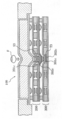
- FIG. 8 is a cross-sectional view schematically showing the internal structure of the operating device 100 described in Patent Document 1.
- the operating device 100 includes both a first detection unit 200 and a second detection unit 300 configured by a membrane switch, and is below the first detection unit 200 (in the pressing direction). Second detection means 300 is provided.
- the portion directly touched by the user's finger F is formed of a flexible member.
- the flexible member is bent to transmit the pressing load to the first detecting means 200. To do.
- the user depresses the finger F at a position corresponding to the first contact S3 with a low load (first operating force) the first upper conductive portion 201c and the first lower conductive portion 202c come into contact with each other.
- the first contact S3 conducts, and this is used as the first stage input. Further, when the finger F is pushed down by applying a high load (second operating force) larger than the low load, the second upper conductive portion 301c and the second lower conductive portion 302c come into contact with each other, and the second The contact T3 conducts, and this is used as the second stage input.
- the first contact S ⁇ b> 3 when the operation device 100 is pressed by the second operating force of the user's finger F, the first contact S ⁇ b> 3 not only detects the first-stage input but also the second input. This shows a state where the contact T3 has detected up to the second stage input.
- Such an input device can assign different operations to each of these stages by receiving the input in two stages according to the pressing load of the user's input.
- the user uses a single switch (input device) to adjust a pressing force when performing one operation of performing a pressing input to the switch, thereby allowing a plurality of Can be distinguished from each other.
- the first-stage input can be performed by keeping the user pressing the button with a weak pressing force.
- Such an input state is also referred to as “half-press”, and is hereinafter referred to as “first-stage input”.
- the user can perform the second-stage input by pressing the button with a stronger pressing force than the first-stage input.
- Such an input state is also referred to as “full press”, and is hereinafter referred to as “second stage input”.
- a shutter button of a camera exists as an example of a typical application of an input device that receives input in two stages according to a pressing load by such a mechanical switch.
- the user can turn on the autofocus process by performing a “half-press” input for performing a first-stage input.
- a “half-press” input for performing a first-stage input.
- an operation of releasing the shutter can be performed, and a still captured image can be acquired.
- different operations can be assigned to the first-stage input and the second-stage input, and the user can distinguish and operate the different operations as desired.
- an input device that accepts a plurality of steps of input according to the pressing load is not limited to a mechanical switch.
- an input device that accepts a plurality of stages of input in response to a pressing load by performing processing by software has been proposed (for example, , See Patent Document 2).
- the touch panel type input device described in Patent Document 2 includes a position detection unit that detects a pressing operation position of a touch panel provided on a surface portion of a display screen, and a pressure detection unit that detects a pressing operation force on the touch panel. .
- This input device can perform two systems of input, that is, input according to the detection position of the position detection means and multistage input according to detection by the pressure detection means, by a single pressing operation of the touch panel.
- the input of the first system can be performed by the pressing operation position, and at the same time, by the pressing force on the touch panel, Two systems of input can be performed. Therefore, the user can perform two types of inputs by performing a single pressing operation on the touch panel, and can reduce the number of times the pressing operation is performed.
- an input device using a mechanical switch and an input device using a touch panel input can be received in a plurality of stages according to the pressing load.
- a small terminal such as a portable terminal
- specifications such as the arrangement configuration of the membrane switch of the first detection unit 200 and the membrane switch of the second detection unit 300 are already set at the time of design or manufacture. It is specified.
- the degree of flexibility of the members constituting the membrane switch is determined at the time of product manufacture, and it is generally difficult to change the specifications of such a configuration later.
- the user actually performs an input operation to determine how much pressure load the first-stage input is received and how much pressure load is accepted the second-stage input.
- an object of the present invention made in view of such circumstances is an electronic device that accepts an input according to a pressing load, and an autofocus process does not operate properly and an out-of-focus still captured image is acquired.
- An object of the present invention is to provide an electronic device that reduces the risk of the occurrence of such a problem.
- the electronic device is an electronic device that accepts a plurality of stages of input in response to a pressing load, and detects an imaging unit that images a subject and a pressing load of the input by pressing. And when the load detection unit detects a pressing load that satisfies the load standard for receiving the first-stage input, an autofocus process for automatically adjusting the focus on the subject is performed, and is higher than the load standard.
- a control unit that controls to acquire a still captured image when a pressing load that satisfies a load criterion that receives a second-stage input is detected, and the control unit focuses on the subject from when the autofocus process is started.
- the load detection unit detects a pressing load that satisfies the load standard for receiving the input of the second stage until the adjustment of is completed, And controlling so as not to acquire the stop capturing images.
- control unit when the focus adjustment for the subject is completed, the control unit inputs a load reference higher than the pressing load detected by the load detection unit in a second stage. Control is performed so as to set the load reference to be received.
- An electronic device is an electronic device that accepts a plurality of stages of input in accordance with a pressing load, an imaging unit that images a subject, a load detection unit that detects a pressing load of an input due to pressing, When the load detection unit detects a pressing load that satisfies a load criterion for receiving a first-stage input, the load detection unit performs an autofocus process for automatically adjusting the focus on the subject, and performs a second-stage input higher than the load criterion.
- a control unit that controls to acquire a still captured image when a pressing load that satisfies the load standard to be received is detected, and the control unit completes the adjustment of the focus on the subject from the start of the autofocus process In the meantime, the load detection unit controls so as not to detect the pressing load.
- the control unit when the focus adjustment on the subject is completed, the control unit inputs a load reference higher than the pressing load detected by the load detection unit in a second stage. Control is performed so as to set the load reference to be received.
- An electronic device is an electronic device that accepts a plurality of stages of input in accordance with a pressing load, an imaging unit that images a subject, a load detection unit that detects a pressing load of an input due to pressing, A control unit that controls the imaging unit to perform an autofocus process for automatically adjusting a focus on a subject when the load detection unit detects a pressing load that satisfies a load criterion for receiving an input; and The control unit performs control so that the load detection unit does not detect the pressing load from the time when the autofocus process is started to the time when the focus adjustment on the subject is completed, and after the focus adjustment on the subject is completed.
- control is performed so as to acquire a still captured image.
- the autofocus process since the still captured image is not acquired between the time when the autofocus process is started and the time when the focus adjustment on the subject is completed, the autofocus process does not operate properly and the focus is not achieved. It is possible to reduce the possibility that an unacceptable still captured image is acquired.
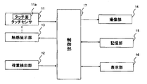
- FIG. 1 is a functional block diagram of an electronic apparatus according to an embodiment of the present invention.
- the electronic device includes a touch sensor 11, a load detection unit 12, a tactile sensation providing unit 13, an imaging unit 14, a storage unit 15, a display unit 16, and a control unit 17 that controls the overall operation. .
- the touch sensor 11 detects a touch by a touch target such as a finger or a stylus pen on the touch surface 11a, and is configured by a resistive film method, a capacitance method, an optical method, and the like, and is disposed on the display unit 16. .
- the load detection unit 12 detects an input pressing load due to pressing, and detects, for example, a pressing load on the touch surface 11 a of the touch sensor 11.
- the load detection unit 12 is configured using an element that reacts to a load such as a strain gauge sensor or a piezoelectric element.
- the tactile sensation providing unit 13 vibrates the touch sensor 11 and is configured using, for example, a piezoelectric element.
- the imaging unit 14 includes an optical system such as an imaging lens, a zoom lens, a focus lens, and an aperture, and a solid-state imaging device such as a CCD (Charge Coupled Device) or a CMOS (Complementary Metal Oxide Semiconductor).
- an optical system such as an imaging lens, a zoom lens, a focus lens, and an aperture
- a solid-state imaging device such as a CCD (Charge Coupled Device) or a CMOS (Complementary Metal Oxide Semiconductor).
- CCD Charge Coupled Device
- CMOS Complementary Metal Oxide Semiconductor
- the storage unit 15 stores various applications and various input information, and also functions as a work memory.
- the storage unit 15 stores a load reference for receiving an input at each stage and a load reference for canceling the input, and a pressing load on the touch surface 11a detected by the load detection unit 12, etc.
- the controller 17 temporarily stores the data for processing.
- the display unit 16 displays various input objects and the like, and is configured using, for example, a liquid crystal display panel or an organic EL display panel.
- the captured image is displayed based on the imaging signal output from the imaging unit 14.
- a display mode by the display unit 16 a captured image is displayed as a moving captured image in real time, a display mode by a so-called live view function, or a captured image is captured by a so-called shutter release operation (an operation to acquire a still captured image).
- a mode of displaying is detected by the control unit 17 based on the position information output from the touch sensor 11.
- the control unit 17 includes, for example, a CPU, and controls the operation of each unit based on position information from the touch sensor 11 and pressure load information from the load detection unit 12.
- the control unit 17 also controls the optical system of the imaging unit 14 and performs autofocus processing for automatically adjusting the focus on the subject. Since the autofocus process itself is a well-known technique, the type of the autofocus process is not particularly limited in the present invention, and various autofocus processes can be applied. Further, when a touch by a touch target on a subject displayed on the display unit 16 by the live view function is detected, an autofocus process for the subject can be started.
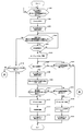
- FIG. 2 is a flowchart for explaining the flow of input processing by the electronic apparatus according to the present embodiment.
- the imaging function is activated and a captured image including a subject is displayed on the display unit 16 by a so-called live view function.
- the control unit 17 detects a touch by a touch target such as a finger on the touch surface 11 a of the touch sensor 11, and further, a pressing load related to the touch by the touch target such as a finger detected by the load detection unit 12 is first. It is determined whether or not a load standard (referred to as “first input accepted load standard”) Fa1 for receiving the input of the stage is satisfied (step S101). When the pressing load detected by the load detection unit 12 satisfies the first input acceptance load standard Fa1, the control unit 17 accepts the first-stage input (step S102).
- first input accepted load standard referred to as “first input accepted load standard”
- step S103 the control unit 17 causes the tactile sensation providing unit 13 to present the tactile sensation A to the finger touching the touch surface 11a in order to notify the user that the first-stage input has been accepted.
- step S ⁇ b> 103 the control unit 17 determines that the pressing load related to the touch by the touch target detected by the load detection unit 12 is the first load reference (“first input cancellation”) that cancels the first-stage input reception.
- first load criterion A second load criterion (referred to as “load criterion”) that accepts a second-stage input that satisfies Fr1 and is higher than the first input release load criterion Fr1 and the first input acceptance load criterion Fa1. It is determined whether Fa2 (referred to as “load reference”) is not satisfied (step S104).
- control unit 17 determines that the pressing load related to the touch by the touch target detected by the load detection unit 12 satisfies the first input release load criterion Fr1 and the second input acceptance load criterion Fa2. If not, the process proceeds to step S105, and if not, the process proceeds to step S119.
- step S105 the control unit 17 continuously detects a pressing load that the load detection unit 12 satisfies the first input release load criterion Fr1 and does not satisfy the second input acceptance load criterion Fa2 for a predetermined time. It is determined whether or not there is (step S105). In step S105, it is determined that the load detection unit 12 continuously detects a pressing load that satisfies the first input release load criterion Fr1 and does not satisfy the second input acceptance load criterion Fa2. Then, it progresses to step S106, and if it is judged that it is not detected continuously for the predetermined time, it will return to step S104.
- step S106 the control unit 17 controls the optical system and the like of the imaging unit 14 and starts autofocus processing so that the focus is automatically adjusted on the subject.
- the subject whose focus is to be automatically adjusted may be determined by the user touching the subject displayed on the display unit 16 by the live view function.
- the control unit 17 determines whether or not the focus adjustment for the subject has been completed (the subject is in focus) by controlling the optical system and the like of the imaging unit 14 (step S107).
- the control unit 17 applies a touch target such as a finger touching the touch surface 11a to notify the user that the focus adjustment for the subject has been completed.
- the tactile sensation providing unit 13 is controlled so as to present the tactile sensation B (step S108).
- the tactile sensation B presented to the touch target may be the same tactile sensation as the tactile sensation A, or may be a different tactile sensation.
- step S108 the control unit 17 newly adds the second input acceptance load reference Fa′2 (after the change) based on the pressing load detected by the load detection unit 12 when the focus adjustment on the subject is completed.
- a second input acceptance load reference Fa′2) is set (step S109).
- the newly set second input acceptance load reference Fa′2 is a load reference higher than the pressing load detected by the load detection unit 12 when the focus adjustment on the subject is completed.
- step S107 if it is determined in step S107 that the focus adjustment for the subject has not been completed, the control unit 17 does not satisfy the first input release load reference Fr1 as the pressing load detected by the load detection unit 12. Whether or not (step S110). If it is determined that the pressing load detected by the load detection unit 12 does not satisfy the first input release load reference Fr1, the process proceeds to step S116, and if it is determined to satisfy, the process returns to step S107.
- the control unit 17 determines that the pressing load detected by the load detection unit 12 is the second input acceptance load after this change. It is determined whether or not the criterion Fa′2 is satisfied (step S111). If it is determined in step S111 that the pressing load detected by the load detection unit 12 satisfies the second input acceptance load reference Fa′2 after the change, the second input is accepted (step S112), and the subject A still captured image including is acquired (step S113).
- acquisition of a still captured image is, for example, a mode of temporarily storing in a RAM or the like of the storage unit 15 or a mode of storing in a ROM or the like.
- the control unit 17 presents a tactile sensation so as to present a tactile sensation C to a touch target such as a finger touching the touch surface 11a in order to notify the user that a still captured image has been acquired.
- the unit 13 is controlled (step S114), and this process is terminated.
- the tactile sensation C presented to the touch target may be the same tactile sensation as the tactile sensation A or tactile sensation B, or may be a different tactile sensation.
- step S111 determines whether or not the pressing load detected by the load detection unit 12 does not satisfy the second input acceptance load reference Fa′2 after the change.
- step S115 it is determined whether or not the first input release load reference Fr1 is not satisfied.
- the control unit 17 presents a tactile sensation D to a touch target such as a finger touching the touch surface 11a in order to notify the user that the autofocus process has stopped.
- the tactile sensation providing unit 13 is controlled (step S118), and this process is terminated.
- the tactile sensation D presented to the touch target may be the same tactile sensation as the tactile sensation A, tactile sensation B, or tactile sensation C, or may be a different tactile sensation.
- step S104 the control unit 17 does not detect the pressing load that the load detection unit 12 satisfies the first input release load criterion Fr1 and does not satisfy the second input acceptance load criterion Fa2. If it judges, it will progress to step S119.
- the control unit 17 determines whether or not the pressing load detected by the load detection unit 12 satisfies the second input acceptance load reference Fa2, and if the determination is satisfied, the process proceeds to step S112. The process proceeds to step S116.
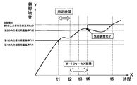
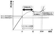
- FIG. 3 is a graph showing how the pressing load detected by the load detection unit 12 changes.
- the X-axis direction represents the transition of time
- the Y-axis direction represents the pressing load detected by the load detection unit 12.
- the time when the user touches the touch surface 11a of the touch sensor 11 is the origin, and the pressing load at that time is zero.
- the pressing load detected by the load detection unit 12 increases with time by applying a pressing force to the touch surface 11a.
- the pressing load detected by the load detector 12 reaches (satisfies) the first input acceptance load reference Fa1, and the first-stage input is accepted.
- the control unit 17 controls the tactile sensation providing unit 13 so as to present a tactile sensation with respect to the touch target touching the touch surface 11a, so that the user has received the first-stage input. Can know.
- the control unit 17 determines that the load detection unit 12 is not suitable for acquiring a still captured image until the adjustment of the focus on the subject is completed. Even when a pressing load that satisfies the load reference Fa2 is detected (at time t3), control is performed so that a still captured image including the subject is not acquired. By controlling in this way, a still captured image in which the subject is not focused is not erroneously acquired.
- a new second input acceptance load reference Fa′2 is set based on the pressing load detected by the load detection unit 12 at that time. To do. If it is determined whether or not to acquire a still captured image based on the second input acceptance load criterion Fa2 before the change without using the second input acceptance load criterion Fa′2 after the change, is autofocus processing performed? A pressing load that satisfies the second input acceptance load standard Fa2 before the change is detected from the start to the completion of the focus adjustment on the subject, and the load detection is performed even when the focus adjustment is completed.
- a new second input acceptance load reference Fa′2 is set based on the pressing load detected by the load detection unit 12 when the focus adjustment is completed. In this way, by setting a new second input acceptance load reference, the user does not acquire a still captured image unless the user intentionally applies further pressing force after the subject is focused. To.
- the user consciously increases the pressing force and causes the load detection unit 12 to detect a pressing load that satisfies the changed second input acceptance load reference Fa′2 (at time t5). ), A still captured image can be acquired.
- the load detection unit 12 sets the second input acceptance load reference Fa2 from the time when the autofocus process is started until the focus adjustment is completed on the subject. Control is performed so that a still captured image including the subject is not acquired even when a pressing load that satisfies the condition is detected, so that a possibility that a still captured image that is not focused on the subject is erroneously acquired can be reduced.
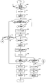
- step S201 After starting the autofocus process in step S106, the control unit 17 stops load detection by the load detection unit 12 (step S201). After stopping the load detection, it is determined whether or not the focus adjustment for the subject is completed based on the autofocus process, and the process does not proceed to the next step until the focus adjustment is completed (step S202). If it is determined in step S202 that the focus adjustment for the subject has been completed, the processing in steps S108 and S109 is performed as in the first embodiment. Then, the control part 17 restarts the load detection by the load detection part 12 (step S203). The processing after step S203 is the same as that in the first embodiment.
- FIG. 5 is a graph showing how the pressing load detected by the load detection unit 12 changes.
- the X-axis direction represents the transition of time, and the Y-axis direction represents the pressing load detected by the load detection unit 12.
- the time when the user touches the touch surface 11a of the touch sensor 11 is the origin, and the pressing load at that time is zero.
- the control unit 17 stops the pressing load detection process by the load detection unit 12, and at the time point t4, the focus of the subject is focused.
- the detection process of the pressing load by the load detection unit 12 is resumed. Therefore, since the load detection is not performed from the time when the autofocus process is started to the time when the focus adjustment with respect to the subject is completed, the load detection unit 12 detects a pressing load that satisfies the second input acceptance load standard. None do. Therefore, the possibility that a still captured image is erroneously acquired while the subject is not in focus is reduced.
- step S101 when the control unit 17 determines in step S101 that the pressing load detected by the load detection unit 12 satisfies the first input reception load criterion Fa1, the control unit 17 receives the first input.
- Step S102 the tactile sensation providing unit 13 is controlled to present a tactile sensation to the touch target touching the touch surface 11a (step S301).
- step S301 after step S301, the processing of steps S104 and S105 described in the flowcharts of FIGS. 2 and 4 according to the first and second embodiments is omitted, and the process proceeds to step S106.
- step S302 the control unit 17 detects the load change amount of the pressing load exceeding the predetermined load change amount per unit time. Whether or not (step S302). If it is determined that the load detection unit 12 has detected a load change amount of a pressing load exceeding a predetermined load change amount per unit time, the processes of step S112, step S113, and step S114 are performed as in the second embodiment. On the other hand, if it is determined that the load detection unit 12 has not detected the load change amount of the pressing load exceeding the predetermined load change amount per unit time, the process of step S115 is performed as in the second embodiment.
- FIG. 7 is a graph showing how the pressing load detected by the load detector 12 changes.
- the X-axis direction represents the transition of time
- the Y-axis direction represents the pressing load detected by the load detection unit 12.
- the time when the user touches the touch surface 11a of the touch sensor 11 is the origin, and the pressing load at that time is zero.
- control unit 17 detects the load change amount of the pressing load exceeding the predetermined load change amount per unit time after the autofocus process is completed at the time point t2. Then, a still captured image of the subject is acquired (at time t4).
- the load detection unit 12 detects a load change amount of a pressing load exceeding a predetermined load change amount per unit time, a still captured image is acquired. Since it is a structure, a possibility that a still picked-up image will be erroneously acquired in a state where the subject is not in focus is reduced.
- control is performed so that a still captured image is not acquired from the time when autofocus processing is started until the time when focus adjustment on the subject is completed, but the present invention is not limited to this.
- this process can be applied to an automatic exposure process.
- the load detection unit 12 detects a pressing load that satisfies the first input acceptance load criterion
- the automatic exposure process is started, and the automatic exposure process is started and then the aperture of the image pickup unit 14 is controlled to be optimal. Control may be performed so that a still captured image is not acquired until exposure is determined.
- the load detection unit 12 detects a pressing load that satisfies the first input acceptance load criterion, the auto focus process and the automatic exposure process are started, and after starting the auto focus process and the automatic exposure process, the subject Control may be performed so that a still captured image is not acquired until the focus adjustment with respect to is completed and until the optimum exposure is determined, whichever is later.
- the position of the touch sensor 11 is not particularly limited, and the touch sensor 11 may be appropriately disposed.
- the touch sensor 11 according to the present invention may be provided in place of the release button of a camera or the like, or the touch sensor 11 may be arranged in parallel with the display unit 14 to form a so-called touch panel.
- step S104 and step S105 are performed, but this may be omitted. That is, after performing the process of step S103, the process of step S106 is performed.
- the load detection unit 12 detects a pressing load that satisfies the first input acceptance load standard, the autofocus process starts before a predetermined time elapses.
- the display unit 16 and the touch sensor 11 in the description of the present embodiment may be configured by an integrated device by providing both functions on a common substrate.
- a plurality of photoelectric conversion elements such as photodiodes are regularly arranged in a matrix electrode array of pixel electrodes included in the liquid crystal panel. Some are mixed.
- This device displays an image with a liquid crystal panel structure, while reflecting the light of a backlight for liquid crystal display at the tip of a pen that touches and inputs a desired position on the surface of the panel. The reflected light is reflected by peripheral photoelectric conversion elements. By receiving the light, the touch position can be detected.
- the piezoelectric element since the piezoelectric element generates electric power when pressure is applied and deforms when electric power is applied, the piezoelectric element can be used to share the load detection unit 12 and the tactile sensation providing unit 13.
- the touch sensor 11 since the touch sensor 11 can detect a change in resistance per time or a change in capacitance per time, the load sensor 12 and the touch sensor 11 can be used in common.
Landscapes
- Engineering & Computer Science (AREA)
- Physics & Mathematics (AREA)
- General Physics & Mathematics (AREA)
- Theoretical Computer Science (AREA)
- General Engineering & Computer Science (AREA)
- Human Computer Interaction (AREA)
- Signal Processing (AREA)
- Multimedia (AREA)
- Optics & Photonics (AREA)
- Studio Devices (AREA)
- User Interface Of Digital Computer (AREA)
- Focusing (AREA)
- Details Of Cameras Including Film Mechanisms (AREA)
- Camera Bodies And Camera Details Or Accessories (AREA)
- Automatic Focus Adjustment (AREA)
Abstract
Description
11a タッチ面
12 荷重検出部
13 触感呈示部
14 撮像部
15 表示部
16 記憶部
17 制御部
図1は、本発明の実施の形態に係る電子機器の機能ブロック図である。図1に示すように、電子機器は、タッチセンサ11、荷重検出部12、触感呈示部13、撮像部14、記憶部15、表示部16、および、全体の動作を制御する制御部17を有する。
次に、本発明の第2実施の形態に係る電子機器について説明する。本発明の第2実施の形態は、上述した第1実施の形態において、図2で説明したステップS106におけるオートフォーカス処理が開始された後の処理を変更する。第2実施の形態に係る電子機器は、第1実施の形態で説明した電子機器と同じ構成により実施することができ、制御部17の処理および動作が異なるものである。したがって、上述した第1実施の形態と同じ説明、同じ効果の記載は適宜省略する。
次に、本発明の第3実施の形態に係る電子機器について説明する。本発明の第3実施の形態は、第1および第2実施の形態と異なり、荷重検出部12が、単位時間あたりの所定荷重変化量を超える荷重変化量を検出すると、制御部17は、静止撮像画像を取得する。第3実施の形態に係る電子機器は、第2実施の形態で説明した電子機器と同じ構成により実施することができ、制御部17の処理および動作が異なるものである。したがって、上述した第2実施の形態と同じ説明、同じ効果の記載は適宜省略する。
Claims (5)
- 押圧荷重に応じて複数段階の入力を受け付ける電子機器であって、
被写体を撮像する撮像部と、
押圧による入力の押圧荷重を検出する荷重検出部と、
前記荷重検出部が、第1段階の入力を受け付ける荷重基準を満たす押圧荷重を検出すると、被写体に対して焦点を自動で調整するオートフォーカス処理を行い、前記荷重基準より高い第2段階の入力を受け付ける荷重基準を満たす押圧荷重を検出すると、静止撮像画像を取得するように制御する制御部と、を備え、
前記制御部は、オートフォーカス処理を開始したときから被写体に対する焦点の調整が完了するときまでの間に、前記荷重検出部が、前記第2段階の入力を受け付ける荷重基準を満たす押圧荷重を検出した場合には、静止撮像画像を取得しないように制御することを特徴とする電子機器。 - 前記制御部は、被写体に対する焦点の調整が完了した際に、前記荷重検出部が検出している押圧荷重より高い荷重基準を、第2段階の入力を受け付ける荷重基準として設定するように制御することを特徴とする請求項1に記載の電子機器。
- 押圧荷重に応じて複数段階の入力を受け付ける電子機器であって、
被写体を撮像する撮像部と、
押圧による入力の押圧荷重を検出する荷重検出部と、
前記荷重検出部が、第1段階の入力を受け付ける荷重基準を満たす押圧荷重を検出すると、被写体に対して焦点を自動で調整するオートフォーカス処理を行い、前記荷重基準より高い第2段階の入力を受け付ける荷重基準を満たす押圧荷重を検出すると、静止撮像画像を取得するように制御する制御部と、を備え、
前記制御部は、オートフォーカス処理を開始したときから被写体に対する焦点の調整が完了するときまでの間、前記荷重検出部が、押圧荷重を検出しないように制御することを特徴とする電子機器。 - 前記制御部は、被写体に対する焦点の調整が完了した際に、前記荷重検出部が検出している押圧荷重より高い荷重基準を、第2段階の入力を受け付ける荷重基準として設定するように制御することを特徴とする請求項3に記載の電子機器。
- 押圧荷重に応じて複数段階の入力を受け付ける電子機器であって、
被写体を撮像する撮像部と、
押圧による入力の押圧荷重を検出する荷重検出部と、
前記荷重検出部が、入力を受け付ける荷重基準を満たす押圧荷重を検出すると、被写体に対して焦点を自動で調整するオートフォーカス処理を行うように前記撮像部を制御する制御部と、を備え、
前記制御部は、オートフォーカス処理を開始したときから被写体に対する焦点の調整が完了するときまでの間、前記荷重検出部が、押圧荷重を検出しないように制御し、被写体に対する焦点の調整が完了した後には、前記荷重検出部が、単位時間当たりの所定荷重変化量を超える荷重変化量を検出すると、静止撮像画像を取得するように制御することを特徴とする電子機器。
Priority Applications (3)
| Application Number | Priority Date | Filing Date | Title |
|---|---|---|---|
| CN201180010403.9A CN102763017B (zh) | 2010-02-22 | 2011-01-26 | 电子设备 |
| US13/580,376 US9152015B2 (en) | 2010-02-22 | 2011-01-26 | Electronic device |
| JP2012500535A JP5670996B2 (ja) | 2010-02-22 | 2011-01-26 | 電子機器 |
Applications Claiming Priority (2)
| Application Number | Priority Date | Filing Date | Title |
|---|---|---|---|
| JP2010036150 | 2010-02-22 | ||
| JP2010-036150 | 2010-02-22 |
Publications (1)
| Publication Number | Publication Date |
|---|---|
| WO2011102192A1 true WO2011102192A1 (ja) | 2011-08-25 |
Family
ID=44482791
Family Applications (1)
| Application Number | Title | Priority Date | Filing Date |
|---|---|---|---|
| PCT/JP2011/051404 Ceased WO2011102192A1 (ja) | 2010-02-22 | 2011-01-26 | 電子機器 |
Country Status (4)
| Country | Link |
|---|---|
| US (1) | US9152015B2 (ja) |
| JP (1) | JP5670996B2 (ja) |
| CN (1) | CN102763017B (ja) |
| WO (1) | WO2011102192A1 (ja) |
Cited By (6)
| Publication number | Priority date | Publication date | Assignee | Title |
|---|---|---|---|---|
| JP2013073518A (ja) * | 2011-09-28 | 2013-04-22 | Kyocera Corp | 電子機器 |
| JP2013228880A (ja) * | 2012-04-25 | 2013-11-07 | Kyocera Corp | 電子機器 |
| JP2014010468A (ja) * | 2012-06-27 | 2014-01-20 | Kyocera Corp | 電子機器 |
| EP2827577A4 (en) * | 2012-03-16 | 2015-10-07 | Ntt Docomo Inc | INFORMATION SENDING DEVICE AND IMAGE CONTROL PROCEDURE |
| US10809857B2 (en) | 2016-01-12 | 2020-10-20 | Murata Manufacturing Co., Ltd. | Electronic device |
| JP2021012258A (ja) * | 2019-07-04 | 2021-02-04 | キヤノン株式会社 | 撮像装置及びその制御方法、プログラム、記憶媒体 |
Families Citing this family (2)
| Publication number | Priority date | Publication date | Assignee | Title |
|---|---|---|---|---|
| JP5795793B2 (ja) * | 2011-03-28 | 2015-10-14 | 富士フイルム株式会社 | レンズ装置及びフォーカス制御方法 |
| CN105824458A (zh) * | 2016-01-29 | 2016-08-03 | 维沃移动通信有限公司 | 一种拍照控制方法及移动终端 |
Citations (9)
| Publication number | Priority date | Publication date | Assignee | Title |
|---|---|---|---|---|
| JPS62112143A (ja) * | 1985-11-12 | 1987-05-23 | Yokohama Rubber Co Ltd:The | カメラシヤツタ−ボタンの制御方法 |
| JPH04125534A (ja) * | 1990-09-17 | 1992-04-27 | Olympus Optical Co Ltd | カメラ |
| JPH054119U (ja) * | 1991-06-28 | 1993-01-22 | 株式会社ニコン | カメラのフオーカスロツク装置 |
| JPH08262519A (ja) * | 1995-03-24 | 1996-10-11 | Canon Inc | 自動構図機能付カメラ及びカメラ |
| JP2006227327A (ja) * | 2005-02-18 | 2006-08-31 | Fuji Photo Film Co Ltd | 撮影装置 |
| JP2007225837A (ja) * | 2006-02-23 | 2007-09-06 | Nikon Corp | 焦点検出制御装置およびカメラ |
| JP2007286185A (ja) * | 2006-04-13 | 2007-11-01 | Fujifilm Corp | 撮影装置、撮影方法及び撮影プログラム |
| JP2007322694A (ja) * | 2006-05-31 | 2007-12-13 | Fujifilm Corp | 撮影装置及び撮影装置の制御方法 |
| JP2009048126A (ja) * | 2007-08-22 | 2009-03-05 | Olympus Imaging Corp | 撮影装置および撮影装置の制御方法 |
Family Cites Families (17)
| Publication number | Priority date | Publication date | Assignee | Title |
|---|---|---|---|---|
| US5204709A (en) * | 1990-09-17 | 1993-04-20 | Olympus Optical Co., Ltd. | Camera apparatus having function for changing condition of release operation |
| JP4310066B2 (ja) * | 2002-01-22 | 2009-08-05 | 富士フイルム株式会社 | デジタルカメラ |
| JP2003295299A (ja) * | 2002-03-29 | 2003-10-15 | Fuji Photo Optical Co Ltd | レリーズボタン装置 |
| JP4224271B2 (ja) * | 2002-09-25 | 2009-02-12 | 富士フイルム株式会社 | カメラ用スイッチ装置 |
| JP2004157353A (ja) * | 2002-11-07 | 2004-06-03 | Minolta Co Ltd | 操作部材に圧力センサを備えたカメラ |
| JP2006025310A (ja) * | 2004-07-09 | 2006-01-26 | Konica Minolta Photo Imaging Inc | 撮像装置 |
| JP2006039745A (ja) | 2004-07-23 | 2006-02-09 | Denso Corp | タッチパネル式入力装置 |
| JP2006134609A (ja) | 2004-11-02 | 2006-05-25 | Alps Electric Co Ltd | 操作装置 |
| JP4591325B2 (ja) * | 2005-01-28 | 2010-12-01 | カシオ計算機株式会社 | 撮像装置及びプログラム |
| JP4797522B2 (ja) * | 2005-09-08 | 2011-10-19 | カシオ計算機株式会社 | 撮像装置及びそのプログラム |
| JP2008015097A (ja) * | 2006-07-04 | 2008-01-24 | Samsung Techwin Co Ltd | 撮像装置及び撮像方法 |
| JP2008146453A (ja) * | 2006-12-12 | 2008-06-26 | Sony Corp | 映像信号出力装置、操作入力処理方法 |
| GB2446702A (en) | 2007-02-13 | 2008-08-20 | Qrg Ltd | Touch Control Panel with Pressure Sensor |
| US7844176B2 (en) | 2007-08-01 | 2010-11-30 | Olympus Imaging Corp. | Imaging device, and control method for imaging device |
| CN101465906B (zh) | 2007-12-19 | 2012-07-18 | 鸿富锦精密工业(深圳)有限公司 | 便携式电子装置 |
| WO2011099361A1 (ja) * | 2010-02-15 | 2011-08-18 | 京セラ株式会社 | 電子機器 |
| JP2013046292A (ja) * | 2011-08-25 | 2013-03-04 | Panasonic Corp | 複眼撮像装置 |
-
2011
- 2011-01-26 JP JP2012500535A patent/JP5670996B2/ja not_active Expired - Fee Related
- 2011-01-26 CN CN201180010403.9A patent/CN102763017B/zh active Active
- 2011-01-26 WO PCT/JP2011/051404 patent/WO2011102192A1/ja not_active Ceased
- 2011-01-26 US US13/580,376 patent/US9152015B2/en not_active Expired - Fee Related
Patent Citations (9)
| Publication number | Priority date | Publication date | Assignee | Title |
|---|---|---|---|---|
| JPS62112143A (ja) * | 1985-11-12 | 1987-05-23 | Yokohama Rubber Co Ltd:The | カメラシヤツタ−ボタンの制御方法 |
| JPH04125534A (ja) * | 1990-09-17 | 1992-04-27 | Olympus Optical Co Ltd | カメラ |
| JPH054119U (ja) * | 1991-06-28 | 1993-01-22 | 株式会社ニコン | カメラのフオーカスロツク装置 |
| JPH08262519A (ja) * | 1995-03-24 | 1996-10-11 | Canon Inc | 自動構図機能付カメラ及びカメラ |
| JP2006227327A (ja) * | 2005-02-18 | 2006-08-31 | Fuji Photo Film Co Ltd | 撮影装置 |
| JP2007225837A (ja) * | 2006-02-23 | 2007-09-06 | Nikon Corp | 焦点検出制御装置およびカメラ |
| JP2007286185A (ja) * | 2006-04-13 | 2007-11-01 | Fujifilm Corp | 撮影装置、撮影方法及び撮影プログラム |
| JP2007322694A (ja) * | 2006-05-31 | 2007-12-13 | Fujifilm Corp | 撮影装置及び撮影装置の制御方法 |
| JP2009048126A (ja) * | 2007-08-22 | 2009-03-05 | Olympus Imaging Corp | 撮影装置および撮影装置の制御方法 |
Cited By (7)
| Publication number | Priority date | Publication date | Assignee | Title |
|---|---|---|---|---|
| JP2013073518A (ja) * | 2011-09-28 | 2013-04-22 | Kyocera Corp | 電子機器 |
| EP2827577A4 (en) * | 2012-03-16 | 2015-10-07 | Ntt Docomo Inc | INFORMATION SENDING DEVICE AND IMAGE CONTROL PROCEDURE |
| JP2013228880A (ja) * | 2012-04-25 | 2013-11-07 | Kyocera Corp | 電子機器 |
| JP2014010468A (ja) * | 2012-06-27 | 2014-01-20 | Kyocera Corp | 電子機器 |
| US10809857B2 (en) | 2016-01-12 | 2020-10-20 | Murata Manufacturing Co., Ltd. | Electronic device |
| JP2021012258A (ja) * | 2019-07-04 | 2021-02-04 | キヤノン株式会社 | 撮像装置及びその制御方法、プログラム、記憶媒体 |
| JP7361510B2 (ja) | 2019-07-04 | 2023-10-16 | キヤノン株式会社 | 撮像装置及びその制御方法、プログラム、記憶媒体 |
Also Published As
| Publication number | Publication date |
|---|---|
| CN102763017B (zh) | 2016-05-18 |
| CN102763017A (zh) | 2012-10-31 |
| JP5670996B2 (ja) | 2015-02-18 |
| JPWO2011102192A1 (ja) | 2013-06-17 |
| US20120314120A1 (en) | 2012-12-13 |
| US9152015B2 (en) | 2015-10-06 |
Similar Documents
| Publication | Publication Date | Title |
|---|---|---|
| JP5670996B2 (ja) | 電子機器 | |
| JP5822591B2 (ja) | 電子機器 | |
| CN101360189B (zh) | 拍照控制方法及其拍照装置 | |
| RU2518987C2 (ru) | Устройство захвата изображения и способ управления им | |
| WO2010122815A1 (ja) | 入力装置および入力方法 | |
| WO2011024457A1 (ja) | 入力装置 | |
| US10447918B2 (en) | Imaging control apparatus and method for controlling the same | |
| US20110013072A1 (en) | Method and apparatus for manual focusing in portable terminal | |
| KR20170063388A (ko) | 전자기기 및 그 제어 방법 | |
| CN103516977A (zh) | 数字拍摄设备及其控制方法 | |
| US20150022704A1 (en) | Orientation-Based Camera Operation | |
| JP5167896B2 (ja) | 設定装置及びプログラム | |
| EP2304932B1 (en) | Image capturing device | |
| US10419678B2 (en) | Imaging control apparatus and method for controlling the same | |
| US20210250491A1 (en) | Image pickup apparatus and electronic device having optical input device | |
| JP5369547B2 (ja) | 撮像装置 | |
| US20220360717A1 (en) | Image capture device | |
| US11169684B2 (en) | Display control apparatuses, control methods therefor, and computer readable storage medium | |
| JP5206226B2 (ja) | 撮像装置及びプログラム | |
| JP5233353B2 (ja) | 設定装置及びプログラム | |
| KR20090129742A (ko) | 터치 스크린을 이용한 줌 기능을 구비한 디지털 카메라와촬상 방법 | |
| CN115811659A (zh) | 一种拍照控制方法、装置、设备及存储介质 | |
| JP2010060690A (ja) | 表示装置 | |
| HK1186028A (en) | Imaging device and imaging processing method | |
| JP2010250523A (ja) | 電子機器の情報入力装置および電子機器の情報入力方法 |
Legal Events
| Date | Code | Title | Description |
|---|---|---|---|
| WWE | Wipo information: entry into national phase |
Ref document number: 201180010403.9 Country of ref document: CN |
|
| 121 | Ep: the epo has been informed by wipo that ep was designated in this application |
Ref document number: 11744481 Country of ref document: EP Kind code of ref document: A1 |
|
| WWE | Wipo information: entry into national phase |
Ref document number: 2012500535 Country of ref document: JP |
|
| WWE | Wipo information: entry into national phase |
Ref document number: 13580376 Country of ref document: US |
|
| NENP | Non-entry into the national phase |
Ref country code: DE |
|
| 122 | Ep: pct application non-entry in european phase |
Ref document number: 11744481 Country of ref document: EP Kind code of ref document: A1 |