WO2011102044A1 - エピタキシャル基板およびエピタキシャル基板の製造方法 - Google Patents
エピタキシャル基板およびエピタキシャル基板の製造方法 Download PDFInfo
- Publication number
- WO2011102044A1 WO2011102044A1 PCT/JP2010/071581 JP2010071581W WO2011102044A1 WO 2011102044 A1 WO2011102044 A1 WO 2011102044A1 JP 2010071581 W JP2010071581 W JP 2010071581W WO 2011102044 A1 WO2011102044 A1 WO 2011102044A1
- Authority
- WO
- WIPO (PCT)
- Prior art keywords
- layer
- group
- superlattice
- epitaxial substrate
- unit
- Prior art date
Links
- 239000000758 substrate Substances 0.000 title claims abstract description 193
- 238000004519 manufacturing process Methods 0.000 title claims description 24
- 150000004767 nitrides Chemical class 0.000 claims abstract description 77
- 239000013078 crystal Substances 0.000 claims abstract description 61
- 239000000203 mixture Substances 0.000 claims abstract description 30
- 229910021421 monocrystalline silicon Inorganic materials 0.000 claims abstract description 13
- 230000001427 coherent effect Effects 0.000 claims description 24
- 238000000034 method Methods 0.000 claims description 15
- 238000010030 laminating Methods 0.000 claims description 14
- 239000004065 semiconductor Substances 0.000 claims description 10
- 230000007547 defect Effects 0.000 claims description 5
- 230000008569 process Effects 0.000 claims description 5
- XUIMIQQOPSSXEZ-UHFFFAOYSA-N Silicon Chemical compound [Si] XUIMIQQOPSSXEZ-UHFFFAOYSA-N 0.000 abstract description 20
- 229910052710 silicon Inorganic materials 0.000 abstract description 20
- 239000010703 silicon Substances 0.000 abstract description 20
- 229910002651 NO3 Inorganic materials 0.000 abstract 1
- NHNBFGGVMKEFGY-UHFFFAOYSA-N Nitrate Chemical compound [O-][N+]([O-])=O NHNBFGGVMKEFGY-UHFFFAOYSA-N 0.000 abstract 1
- 239000010410 layer Substances 0.000 description 417
- 230000015572 biosynthetic process Effects 0.000 description 34
- 238000005755 formation reaction Methods 0.000 description 34
- 239000007789 gas Substances 0.000 description 20
- 239000002346 layers by function Substances 0.000 description 19
- 230000000694 effects Effects 0.000 description 12
- JLTRXTDYQLMHGR-UHFFFAOYSA-N trimethylaluminium Chemical compound C[Al](C)C JLTRXTDYQLMHGR-UHFFFAOYSA-N 0.000 description 12
- 230000000052 comparative effect Effects 0.000 description 11
- XCZXGTMEAKBVPV-UHFFFAOYSA-N trimethylgallium Chemical compound C[Ga](C)C XCZXGTMEAKBVPV-UHFFFAOYSA-N 0.000 description 10
- 230000004888 barrier function Effects 0.000 description 9
- 230000005587 bubbling Effects 0.000 description 9
- KRHYYFGTRYWZRS-UHFFFAOYSA-N Fluorane Chemical compound F KRHYYFGTRYWZRS-UHFFFAOYSA-N 0.000 description 6
- 230000015556 catabolic process Effects 0.000 description 6
- 239000000463 material Substances 0.000 description 6
- 238000009825 accumulation Methods 0.000 description 5
- 238000010586 diagram Methods 0.000 description 5
- 238000004140 cleaning Methods 0.000 description 4
- 229910002704 AlGaN Inorganic materials 0.000 description 3
- 230000010287 polarization Effects 0.000 description 3
- 125000006850 spacer group Chemical group 0.000 description 3
- IJGRMHOSHXDMSA-UHFFFAOYSA-N Atomic nitrogen Chemical compound N#N IJGRMHOSHXDMSA-UHFFFAOYSA-N 0.000 description 2
- QAOWNCQODCNURD-UHFFFAOYSA-N Sulfuric acid Chemical compound OS(O)(=O)=O QAOWNCQODCNURD-UHFFFAOYSA-N 0.000 description 2
- 125000004429 atom Chemical group 0.000 description 2
- 150000001875 compounds Chemical class 0.000 description 2
- 230000006835 compression Effects 0.000 description 2
- 238000007906 compression Methods 0.000 description 2
- 238000006073 displacement reaction Methods 0.000 description 2
- 238000005516 engineering process Methods 0.000 description 2
- 229910052733 gallium Inorganic materials 0.000 description 2
- 239000007791 liquid phase Substances 0.000 description 2
- 230000006911 nucleation Effects 0.000 description 2
- 238000010899 nucleation Methods 0.000 description 2
- 125000004430 oxygen atom Chemical group O* 0.000 description 2
- 238000000206 photolithography Methods 0.000 description 2
- 239000002994 raw material Substances 0.000 description 2
- 230000009467 reduction Effects 0.000 description 2
- 229910052594 sapphire Inorganic materials 0.000 description 2
- 239000010980 sapphire Substances 0.000 description 2
- 230000003746 surface roughness Effects 0.000 description 2
- 230000005533 two-dimensional electron gas Effects 0.000 description 2
- MGYGFNQQGAQEON-UHFFFAOYSA-N 4-tolyl isocyanate Chemical compound CC1=CC=C(N=C=O)C=C1 MGYGFNQQGAQEON-UHFFFAOYSA-N 0.000 description 1
- GYHNNYVSQQEPJS-UHFFFAOYSA-N Gallium Chemical compound [Ga] GYHNNYVSQQEPJS-UHFFFAOYSA-N 0.000 description 1
- UFHFLCQGNIYNRP-UHFFFAOYSA-N Hydrogen Chemical compound [H][H] UFHFLCQGNIYNRP-UHFFFAOYSA-N 0.000 description 1
- MHAJPDPJQMAIIY-UHFFFAOYSA-N Hydrogen peroxide Chemical compound OO MHAJPDPJQMAIIY-UHFFFAOYSA-N 0.000 description 1
- -1 SiC Chemical class 0.000 description 1
- 229910052782 aluminium Inorganic materials 0.000 description 1
- XAGFODPZIPBFFR-UHFFFAOYSA-N aluminium Chemical compound [Al] XAGFODPZIPBFFR-UHFFFAOYSA-N 0.000 description 1
- 230000005540 biological transmission Effects 0.000 description 1
- 238000006243 chemical reaction Methods 0.000 description 1
- 238000005229 chemical vapour deposition Methods 0.000 description 1
- 238000004581 coalescence Methods 0.000 description 1
- 239000004020 conductor Substances 0.000 description 1
- 238000007796 conventional method Methods 0.000 description 1
- 238000005336 cracking Methods 0.000 description 1
- 238000000151 deposition Methods 0.000 description 1
- 230000008021 deposition Effects 0.000 description 1
- 238000013461 design Methods 0.000 description 1
- 230000008034 disappearance Effects 0.000 description 1
- 230000005684 electric field Effects 0.000 description 1
- 238000004146 energy storage Methods 0.000 description 1
- 238000002474 experimental method Methods 0.000 description 1
- 238000010438 heat treatment Methods 0.000 description 1
- 239000001257 hydrogen Substances 0.000 description 1
- 229910052739 hydrogen Inorganic materials 0.000 description 1
- 239000007788 liquid Substances 0.000 description 1
- 238000013507 mapping Methods 0.000 description 1
- 230000008018 melting Effects 0.000 description 1
- 238000002844 melting Methods 0.000 description 1
- 229910052751 metal Inorganic materials 0.000 description 1
- 239000002184 metal Substances 0.000 description 1
- 238000012986 modification Methods 0.000 description 1
- 230000004048 modification Effects 0.000 description 1
- 229910052757 nitrogen Inorganic materials 0.000 description 1
- 125000004433 nitrogen atom Chemical group N* 0.000 description 1
- 238000000059 patterning Methods 0.000 description 1
- 230000000149 penetrating effect Effects 0.000 description 1
- 230000002265 prevention Effects 0.000 description 1
- 238000012545 processing Methods 0.000 description 1
- 230000001737 promoting effect Effects 0.000 description 1
- 230000000644 propagated effect Effects 0.000 description 1
- 230000001902 propagating effect Effects 0.000 description 1
- 238000012827 research and development Methods 0.000 description 1
- 239000002356 single layer Substances 0.000 description 1
- 230000002269 spontaneous effect Effects 0.000 description 1
- 238000005728 strengthening Methods 0.000 description 1
- 230000007704 transition Effects 0.000 description 1
- 238000001947 vapour-phase growth Methods 0.000 description 1
- XLYOFNOQVPJJNP-UHFFFAOYSA-N water Substances O XLYOFNOQVPJJNP-UHFFFAOYSA-N 0.000 description 1
- 229910052984 zinc sulfide Inorganic materials 0.000 description 1
Images

Classifications
-
- C—CHEMISTRY; METALLURGY
- C30—CRYSTAL GROWTH
- C30B—SINGLE-CRYSTAL GROWTH; UNIDIRECTIONAL SOLIDIFICATION OF EUTECTIC MATERIAL OR UNIDIRECTIONAL DEMIXING OF EUTECTOID MATERIAL; REFINING BY ZONE-MELTING OF MATERIAL; PRODUCTION OF A HOMOGENEOUS POLYCRYSTALLINE MATERIAL WITH DEFINED STRUCTURE; SINGLE CRYSTALS OR HOMOGENEOUS POLYCRYSTALLINE MATERIAL WITH DEFINED STRUCTURE; AFTER-TREATMENT OF SINGLE CRYSTALS OR A HOMOGENEOUS POLYCRYSTALLINE MATERIAL WITH DEFINED STRUCTURE; APPARATUS THEREFOR
- C30B29/00—Single crystals or homogeneous polycrystalline material with defined structure characterised by the material or by their shape
- C30B29/10—Inorganic compounds or compositions
- C30B29/40—AIIIBV compounds wherein A is B, Al, Ga, In or Tl and B is N, P, As, Sb or Bi
- C30B29/403—AIII-nitrides
-
- C—CHEMISTRY; METALLURGY
- C30—CRYSTAL GROWTH
- C30B—SINGLE-CRYSTAL GROWTH; UNIDIRECTIONAL SOLIDIFICATION OF EUTECTIC MATERIAL OR UNIDIRECTIONAL DEMIXING OF EUTECTOID MATERIAL; REFINING BY ZONE-MELTING OF MATERIAL; PRODUCTION OF A HOMOGENEOUS POLYCRYSTALLINE MATERIAL WITH DEFINED STRUCTURE; SINGLE CRYSTALS OR HOMOGENEOUS POLYCRYSTALLINE MATERIAL WITH DEFINED STRUCTURE; AFTER-TREATMENT OF SINGLE CRYSTALS OR A HOMOGENEOUS POLYCRYSTALLINE MATERIAL WITH DEFINED STRUCTURE; APPARATUS THEREFOR
- C30B25/00—Single-crystal growth by chemical reaction of reactive gases, e.g. chemical vapour-deposition growth
- C30B25/02—Epitaxial-layer growth
- C30B25/18—Epitaxial-layer growth characterised by the substrate
- C30B25/183—Epitaxial-layer growth characterised by the substrate being provided with a buffer layer, e.g. a lattice matching layer
-
- C—CHEMISTRY; METALLURGY
- C30—CRYSTAL GROWTH
- C30B—SINGLE-CRYSTAL GROWTH; UNIDIRECTIONAL SOLIDIFICATION OF EUTECTIC MATERIAL OR UNIDIRECTIONAL DEMIXING OF EUTECTOID MATERIAL; REFINING BY ZONE-MELTING OF MATERIAL; PRODUCTION OF A HOMOGENEOUS POLYCRYSTALLINE MATERIAL WITH DEFINED STRUCTURE; SINGLE CRYSTALS OR HOMOGENEOUS POLYCRYSTALLINE MATERIAL WITH DEFINED STRUCTURE; AFTER-TREATMENT OF SINGLE CRYSTALS OR A HOMOGENEOUS POLYCRYSTALLINE MATERIAL WITH DEFINED STRUCTURE; APPARATUS THEREFOR
- C30B29/00—Single crystals or homogeneous polycrystalline material with defined structure characterised by the material or by their shape
- C30B29/60—Single crystals or homogeneous polycrystalline material with defined structure characterised by the material or by their shape characterised by shape
- C30B29/68—Crystals with laminate structure, e.g. "superlattices"
-
- H—ELECTRICITY
- H01—ELECTRIC ELEMENTS
- H01L—SEMICONDUCTOR DEVICES NOT COVERED BY CLASS H10
- H01L21/00—Processes or apparatus adapted for the manufacture or treatment of semiconductor or solid state devices or of parts thereof
- H01L21/02—Manufacture or treatment of semiconductor devices or of parts thereof
- H01L21/02104—Forming layers
- H01L21/02365—Forming inorganic semiconducting materials on a substrate
- H01L21/02367—Substrates
- H01L21/0237—Materials
- H01L21/02373—Group 14 semiconducting materials
- H01L21/02381—Silicon, silicon germanium, germanium
-
- H—ELECTRICITY
- H01—ELECTRIC ELEMENTS
- H01L—SEMICONDUCTOR DEVICES NOT COVERED BY CLASS H10
- H01L21/00—Processes or apparatus adapted for the manufacture or treatment of semiconductor or solid state devices or of parts thereof
- H01L21/02—Manufacture or treatment of semiconductor devices or of parts thereof
- H01L21/02104—Forming layers
- H01L21/02365—Forming inorganic semiconducting materials on a substrate
- H01L21/02436—Intermediate layers between substrates and deposited layers
- H01L21/02439—Materials
- H01L21/02455—Group 13/15 materials
- H01L21/02458—Nitrides
-
- H—ELECTRICITY
- H01—ELECTRIC ELEMENTS
- H01L—SEMICONDUCTOR DEVICES NOT COVERED BY CLASS H10
- H01L21/00—Processes or apparatus adapted for the manufacture or treatment of semiconductor or solid state devices or of parts thereof
- H01L21/02—Manufacture or treatment of semiconductor devices or of parts thereof
- H01L21/02104—Forming layers
- H01L21/02365—Forming inorganic semiconducting materials on a substrate
- H01L21/02436—Intermediate layers between substrates and deposited layers
- H01L21/02494—Structure
- H01L21/02496—Layer structure
- H01L21/02505—Layer structure consisting of more than two layers
- H01L21/02507—Alternating layers, e.g. superlattice
-
- H—ELECTRICITY
- H01—ELECTRIC ELEMENTS
- H01L—SEMICONDUCTOR DEVICES NOT COVERED BY CLASS H10
- H01L21/00—Processes or apparatus adapted for the manufacture or treatment of semiconductor or solid state devices or of parts thereof
- H01L21/02—Manufacture or treatment of semiconductor devices or of parts thereof
- H01L21/02104—Forming layers
- H01L21/02365—Forming inorganic semiconducting materials on a substrate
- H01L21/02518—Deposited layers
- H01L21/02521—Materials
- H01L21/02538—Group 13/15 materials
- H01L21/0254—Nitrides
-
- H—ELECTRICITY
- H01—ELECTRIC ELEMENTS
- H01L—SEMICONDUCTOR DEVICES NOT COVERED BY CLASS H10
- H01L29/00—Semiconductor devices adapted for rectifying, amplifying, oscillating or switching, or capacitors or resistors with at least one potential-jump barrier or surface barrier, e.g. PN junction depletion layer or carrier concentration layer; Details of semiconductor bodies or of electrodes thereof ; Multistep manufacturing processes therefor
- H01L29/02—Semiconductor bodies ; Multistep manufacturing processes therefor
- H01L29/12—Semiconductor bodies ; Multistep manufacturing processes therefor characterised by the materials of which they are formed
- H01L29/15—Structures with periodic or quasi periodic potential variation, e.g. multiple quantum wells, superlattices
- H01L29/151—Compositional structures
- H01L29/152—Compositional structures with quantum effects only in vertical direction, i.e. layered structures with quantum effects solely resulting from vertical potential variation
- H01L29/155—Comprising only semiconductor materials
-
- H—ELECTRICITY
- H01—ELECTRIC ELEMENTS
- H01L—SEMICONDUCTOR DEVICES NOT COVERED BY CLASS H10
- H01L29/00—Semiconductor devices adapted for rectifying, amplifying, oscillating or switching, or capacitors or resistors with at least one potential-jump barrier or surface barrier, e.g. PN junction depletion layer or carrier concentration layer; Details of semiconductor bodies or of electrodes thereof ; Multistep manufacturing processes therefor
- H01L29/66—Types of semiconductor device ; Multistep manufacturing processes therefor
- H01L29/68—Types of semiconductor device ; Multistep manufacturing processes therefor controllable by only the electric current supplied, or only the electric potential applied, to an electrode which does not carry the current to be rectified, amplified or switched
- H01L29/76—Unipolar devices, e.g. field effect transistors
- H01L29/772—Field effect transistors
- H01L29/778—Field effect transistors with two-dimensional charge carrier gas channel, e.g. HEMT ; with two-dimensional charge-carrier layer formed at a heterojunction interface
- H01L29/7786—Field effect transistors with two-dimensional charge carrier gas channel, e.g. HEMT ; with two-dimensional charge-carrier layer formed at a heterojunction interface with direct single heterostructure, i.e. with wide bandgap layer formed on top of active layer, e.g. direct single heterostructure MIS-like HEMT
-
- H—ELECTRICITY
- H01—ELECTRIC ELEMENTS
- H01L—SEMICONDUCTOR DEVICES NOT COVERED BY CLASS H10
- H01L29/00—Semiconductor devices adapted for rectifying, amplifying, oscillating or switching, or capacitors or resistors with at least one potential-jump barrier or surface barrier, e.g. PN junction depletion layer or carrier concentration layer; Details of semiconductor bodies or of electrodes thereof ; Multistep manufacturing processes therefor
- H01L29/66—Types of semiconductor device ; Multistep manufacturing processes therefor
- H01L29/86—Types of semiconductor device ; Multistep manufacturing processes therefor controllable only by variation of the electric current supplied, or only the electric potential applied, to one or more of the electrodes carrying the current to be rectified, amplified, oscillated or switched
- H01L29/861—Diodes
- H01L29/872—Schottky diodes
-
- H—ELECTRICITY
- H01—ELECTRIC ELEMENTS
- H01L—SEMICONDUCTOR DEVICES NOT COVERED BY CLASS H10
- H01L33/00—Semiconductor devices with at least one potential-jump barrier or surface barrier specially adapted for light emission; Processes or apparatus specially adapted for the manufacture or treatment thereof or of parts thereof; Details thereof
- H01L33/005—Processes
- H01L33/0062—Processes for devices with an active region comprising only III-V compounds
- H01L33/0066—Processes for devices with an active region comprising only III-V compounds with a substrate not being a III-V compound
- H01L33/007—Processes for devices with an active region comprising only III-V compounds with a substrate not being a III-V compound comprising nitride compounds
-
- H—ELECTRICITY
- H01—ELECTRIC ELEMENTS
- H01L—SEMICONDUCTOR DEVICES NOT COVERED BY CLASS H10
- H01L33/00—Semiconductor devices with at least one potential-jump barrier or surface barrier specially adapted for light emission; Processes or apparatus specially adapted for the manufacture or treatment thereof or of parts thereof; Details thereof
- H01L33/02—Semiconductor devices with at least one potential-jump barrier or surface barrier specially adapted for light emission; Processes or apparatus specially adapted for the manufacture or treatment thereof or of parts thereof; Details thereof characterised by the semiconductor bodies
- H01L33/04—Semiconductor devices with at least one potential-jump barrier or surface barrier specially adapted for light emission; Processes or apparatus specially adapted for the manufacture or treatment thereof or of parts thereof; Details thereof characterised by the semiconductor bodies with a quantum effect structure or superlattice, e.g. tunnel junction
-
- H—ELECTRICITY
- H01—ELECTRIC ELEMENTS
- H01L—SEMICONDUCTOR DEVICES NOT COVERED BY CLASS H10
- H01L33/00—Semiconductor devices with at least one potential-jump barrier or surface barrier specially adapted for light emission; Processes or apparatus specially adapted for the manufacture or treatment thereof or of parts thereof; Details thereof
- H01L33/02—Semiconductor devices with at least one potential-jump barrier or surface barrier specially adapted for light emission; Processes or apparatus specially adapted for the manufacture or treatment thereof or of parts thereof; Details thereof characterised by the semiconductor bodies
- H01L33/12—Semiconductor devices with at least one potential-jump barrier or surface barrier specially adapted for light emission; Processes or apparatus specially adapted for the manufacture or treatment thereof or of parts thereof; Details thereof characterised by the semiconductor bodies with a stress relaxation structure, e.g. buffer layer
Definitions
- the present invention relates to an epitaxial substrate for a semiconductor device, and more particularly to an epitaxial substrate configured using a group III nitride.
- Nitride semiconductors have a wide band gap of direct transition type, a high breakdown electric field, and a high saturation electron velocity. Therefore, semiconductors for light emitting devices such as LEDs and LDs, and high frequency / high power electronic devices such as HEMTs. It is attracting attention as a material.
- a HEMT (High Electron Mobility Transistor) element formed by laminating a barrier layer made of AlGaN and a channel layer made of GaN has a laminated interface due to a large polarization effect (spontaneous polarization effect and piezoelectric polarization effect) peculiar to nitride materials. This utilizes the feature that a high-concentration two-dimensional electron gas (2DEG) is generated at the (heterointerface) (for example, see Non-Patent Document 1).
- 2DEG high-concentration two-dimensional electron gas
- a single crystal (heterogeneous single crystal) having a composition different from that of group III nitride, such as SiC, is used as a base substrate used for an epitaxial substrate for HEMT devices.
- a buffer layer such as a strained superlattice layer or a low temperature growth buffer layer is generally formed on the base substrate as an initial growth layer. Therefore, epitaxially forming the barrier layer, the channel layer, and the buffer layer on the base substrate is the most basic configuration of the HEMT element substrate using the base substrate made of different single crystals.
- a spacer layer having a thickness of about 1 nm may be provided between the barrier layer and the channel layer for the purpose of promoting spatial confinement of the two-dimensional electron gas.
- the spacer layer is made of, for example, AlN. Furthermore, a cap layer made of, for example, an n-type GaN layer or a superlattice layer is formed on the barrier layer for the purpose of controlling the energy level at the outermost surface of the substrate for HEMT elements and improving the contact characteristics with the electrode. Sometimes it is done.
- Non-Patent Document 2 It is also already known that increasing the total film thickness of the channel layer and the barrier layer and improving the dielectric breakdown strength of both layers are effective for making the HEMT device epitaxial substrate have a high withstand voltage structure. (For example, see Non-Patent Document 2).
- an intervening layer made of AlN is formed on the Si base substrate, and then the first semiconductor layer made of GaN and the second semiconductor layer made of AlN are alternately formed, however, as a whole, a convex warp occurs.
- a method of manufacturing a semiconductor device is also known in which the warpage of the entire substrate is canceled as a result of the shrinkage of these layers when the temperature is subsequently lowered (see, for example, Patent Document 4).
- the thermal expansion coefficient of a nitride material is larger than that of silicon, in the process of epitaxially growing a nitride film on a silicon substrate at a high temperature and then lowering the temperature to near room temperature, a tensile stress is generated in the nitride film. Work. As a result, cracks are likely to occur on the film surface, and large warpage is likely to occur in the substrate.
- TMG trimethylgallium
- Patent Document 1 to Patent Document 3 and Non-Patent Document 1 When the conventional techniques disclosed in Patent Document 1 to Patent Document 3 and Non-Patent Document 1 are used, it is possible to epitaxially grow a GaN film on a silicon substrate. However, the crystal quality of the obtained GaN film is never better than that obtained when SiC or sapphire is used as the base substrate. For this reason, when an electronic device such as a HEMT is manufactured using the conventional technology, there are problems that the electron mobility is low and the leakage current and breakdown voltage at the time of OFF are low.
- Patent Document 4 intentionally causes a large convex warp in the middle of device fabrication, so that cracks may occur in the middle of device fabrication depending on the layer formation conditions.
- the present invention has been made in view of the above problems, and an object of the present invention is to provide an epitaxial substrate that uses a silicon substrate as a base substrate and is crack-free and reduced in warpage.
- the (0001) crystal plane is substantially parallel to the substrate surface of the base substrate on the base substrate which is single crystal silicon of (111) orientation.
- an epitaxial substrate formed with a group III nitride layer group is a superlattice layer formed by alternately and repeatedly laminating first unit layers and second unit layers made of group III nitrides having different compositions.
- the superlattice layer group contains compressive strain, and in the superlattice layer group, the compressive strain is increased as the superlattice layer formed away from the base substrate.
- the second group III nitride constituting the second unit layer rather than the first group III nitride constituting the first unit layer.
- An object has a larger in-plane lattice constant in an unstrained state, and each of the second unit layers is formed in a coherent state with respect to the first unit layer immediately below the first unit layer.
- the thickness of the second unit layer was made larger in the superlattice layer formed in the above.
- the epitaxial substrate according to the first or second aspect is formed immediately above the superlattice layer group, and the compressive strain introduced into the epitaxial substrate by the superlattice layer group is reduced.
- An intermediate layer for further strengthening was further provided.
- the intermediate layer is made of a group III nitride and is formed in a coherent state with respect to the superlattice layer group.
- a group III nitride layer is formed on a base substrate that is single crystal silicon of (111) orientation so that the (0001) crystal plane is substantially parallel to the substrate surface of the base substrate.
- a plurality of superlattice layers in which an epitaxial substrate formed of a group is a superlattice layer in which first unit layers and second unit layers made of group III nitrides each having a different composition are alternately stacked.
- the second group III nitride constituting the second unit layer has a larger in-plane lattice constant in the unstrained state than the nitride, and each of the second unit layers is formed in the first unit layer directly below the second unit layer. Formed in a coherent state with respect to the superlattice layer group. As it formed the superlattice layer, and so a large thickness of the second unit layer.
- the epitaxial substrate according to the fifth aspect is formed immediately above the superlattice layer group, is made of a group III nitride, and is formed in a coherent state with respect to the superlattice layer group.
- An intermediate layer is further provided.
- the first unit layer is made of AlN
- the second unit layer is made of Al x Ga 1-x N (0 ⁇ x ⁇ 0.25) is made of a group III nitride having a composition.
- the intermediate layer is a group III nitride having a composition of Al y Ga 1-y N (0 ⁇ y ⁇ 0.25) and is 50 nm or more. It was formed to have a thickness of 250 nm or less.
- an epitaxial substrate includes a first underlayer made of AlN formed on the undersubstrate, and the first underlayer. And a second underlayer formed of Al p Ga 1-p N (0 ⁇ p ⁇ 1), wherein the first underlayer is made of columnar or granular crystals or domains. It is a polycrystal defect-containing layer composed of at least one kind, and an interface between the first underlayer and the second underlayer is a three-dimensional uneven surface, and the above-described second underlayer is directly above the second underlayer.
- a superlattice layer group was formed.
- a group III nitride layer group in which a (0001) crystal plane is substantially parallel to a substrate surface of the base substrate is formed on a base substrate that is single crystal silicon of (111) orientation.
- the method for manufacturing an epitaxial substrate for a semiconductor device includes a plurality of steps of forming a superlattice layer by repeatedly laminating first unit layers and second unit layers made of group III nitrides having different compositions.
- a superlattice layer group forming step for forming a superlattice layer group formed by laminating a plurality of superlattice layers, and a crystal layer made of a group III nitride is formed above the superlattice layer group.
- a crystal layer forming step wherein in the superlattice layer group forming step, the first unit layer and the second unit layer are made more than the first group III nitride constituting the first unit layer.
- the second group III nitride constituting the second unit layer is less.
- the superlattice layer formed above the second unit layer so as to be coherent with the first unit layer immediately below the second unit layer so that an in-plane lattice constant in the state increases.
- the second unit layer is formed to have a large thickness.
- an intermediate layer made of a group III nitride is coherent with respect to the superlattice layer group immediately above the superlattice layer group. And an intermediate layer forming step for forming such a state.
- the first unit layer is formed of AlN
- the second unit layer is formed of Al x Ga 1-x N.
- a group III nitride having a composition (0 ⁇ x ⁇ 0.25) was used.
- the intermediate layer is made of a group III nitride having a composition of Al y Ga 1-y N (0 ⁇ y ⁇ 0.25).
- the thickness is 50 nm or more and 250 nm or less.
- a method of manufacturing an epitaxial substrate according to any one of the tenth to thirteenth aspects includes forming a first ground layer made of AlN on the ground substrate. A forming step; and a second underlayer forming step of forming a second underlayer made of Al p Ga 1-p N (0 ⁇ p ⁇ 1) on the first underlayer,
- the first underlayer is formed as a polycrystalline defect-containing layer composed of at least one of columnar or granular crystals or domains and having a three-dimensional uneven surface.
- the superlattice layer group forming step the superlattice layer group is formed immediately above the second underlayer.
- the compressive strain is inherent in the superlattice layer group, the tensile stress caused by the difference in thermal expansion coefficient between silicon and the group III nitride is the compressive strain. Is offset by As a result, even when a silicon substrate is used as the base substrate, an epitaxial substrate with excellent crystal quality and crack-free warpage can be obtained.
- the compressive strain introduced by the superlattice layer group is strengthened, so that the tensile stress is more appropriately offset.
- curvature is more effectively reduced and crack free is more reliably realized.
- the superlattice layer group since the superlattice layer group is provided on the underlayer having low dislocations and excellent surface flatness, the superlattice layer group and the crystal layer have good crystal quality. It will have. On the other hand, since the accumulation of strain energy in the second underlayer is suppressed, the effect of canceling the tensile stress due to the compressive strain contained in the superlattice layer group is hindered by the accumulation of strain energy in the underlayer. None happen.
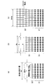
- FIG. 1 is a schematic cross-sectional view schematically showing a configuration of an epitaxial substrate 10 according to an embodiment of the present invention.
- FIG. 4 is a model diagram showing a state of a crystal lattice when a second unit layer 32 is formed on a first unit layer 31.
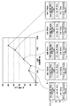
- 3 is a diagram in which the amount of warpage of an epitaxial substrate that has been performed up to formation of the intermediate layer 6 is plotted against the thickness of the intermediate layer 6.
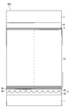
- FIG. 2 is a schematic cross-sectional view schematically showing a configuration of an epitaxial substrate 100 according to a comparative example.
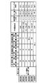
- FIG. It is a figure which shows the manufacturing conditions peculiar to each, the total film thickness, the curvature amount, and the presence or absence of generation
- FIG. 1 is a schematic cross-sectional view schematically showing a configuration of an epitaxial substrate 10 according to an embodiment of the present invention.
- the epitaxial substrate 10 mainly includes a base substrate 1, a base layer 2, a superlattice layer group 5 in which a plurality of superlattice layers 3 and a termination layer 4 are stacked, an intermediate layer 6, and a functional layer 7.
- each layer formed on the base substrate 1 may be collectively referred to as an epitaxial film.
- the base substrate 1 is a (111) plane single crystal silicon wafer having p-type conductivity. Although there is no special restriction
- the underlayer 2, the respective superlattice layers 3, the termination layer 4, the intermediate layer 6, and the functional layer 7 are each composed of a wurtzite group III nitride and a (0001) crystal plane of the undersubstrate 1 It is a layer formed by an epitaxial growth technique so as to be substantially parallel to the substrate surface. These layers are preferably formed by metal organic chemical vapor deposition (MOCVD).
- MOCVD metal organic chemical vapor deposition
- the underlayer 2 is a layer provided to enable the above-described layers to be formed with good crystal quality. Specifically, the underlayer 2 is provided so that the dislocation density is suitably reduced and the crystal quality is good at least near the surface (in the vicinity of the interface with the superlattice layer 3). Thereby, good crystal quality can be obtained in the superlattice layer 3 and also in each layer formed thereon.
- the base layer 2 includes a first base layer 2a and a second base layer 2b as shown below.
- the first underlayer 2a is a layer made of AlN.
- the first underlayer 2a is made up of a number of fine columnar crystals and the like (at least one of columnar crystals, granular crystals, columnar domains, or granular domains) grown in a direction substantially perpendicular to the substrate surface of the underlying substrate 1 (film formation direction). It is a composed layer.
- the first underlayer 2a is uniaxially oriented in the stacking direction of the epitaxial substrate 10, but contains a large number of crystal grain boundaries or dislocations along the stacking direction and has multiple crystal defects with poor crystallinity. It is a content layer.
- the term “crystal grain boundary” including domain grain boundaries or dislocations may be used.
- the distance between crystal grain boundaries in the first underlayer 2a is about several tens of nm at most.
- the first underlayer 2a having such a configuration has an X-ray rocking curve half-value width of (0002) plane that is a large or small mosaic property with respect to the c-axis tilt component or a slight index of screw dislocation, of 0.5 degrees or more.
- X-ray rocking curve half-value width of (10-10) plane which is less than 1 degree and is a measure of the degree of mosaicity or some degree of edge dislocation with respect to the rotational component of the crystal with c axis as the rotation axis Is formed to be 0.8 degrees or more and 1.1 degrees or less.
- the second underlayer 2b is a layer made of a group III nitride having a composition of Al p Ga 1-p N (0 ⁇ p ⁇ 1) formed on the first underlayer 2a.
- the interface I1 (the surface of the first ground layer 2a) between the first ground layer 2a and the second ground layer 2b is a three-dimensional uneven surface reflecting the external shape such as a columnar crystal constituting the first ground layer 2a. It has become. It is clearly confirmed in the HAADF (high angle scattered electron) image of the epitaxial substrate 10 that the interface I1 has such a shape.
- the HAADF image is a mapping image of the integrated intensity of electrons inelastically scattered at a high angle, obtained by a scanning transmission electron microscope (STEM).
- STEM scanning transmission electron microscope
- the image intensity is proportional to the square of the atomic number, and the portion where an atom with a large atomic number is present is observed brighter (whiter). Therefore, the second underlayer 2b containing Ga is relatively brighter, and Ga The first underlayer 2a that does not contain is observed relatively dark. Thereby, it is easily recognized that the interface I1 between the two is a three-dimensional uneven surface.
- the protrusions 2c of the first base layer 2a are shown to be positioned at approximately equal intervals. However, this is merely for convenience of illustration, and actually, it is not necessarily at equal intervals.
- the convex part 2c is not necessarily located.
- the density of the protrusions 2c is 5 ⁇ 10 9 / cm 2 or more and 5 ⁇ 10 10 / cm 2 or less, and the average interval between the protrusions 2c is 45 nm or more and 140 nm or less. It is formed. When these ranges are satisfied, it is possible to form the functional layer 7 having particularly excellent crystal quality.
- the convex portion 2c of the first base layer 2a indicates a substantially apex position of an upward convex portion on the surface (interface I1).
- the side wall of the convex portion 2c is formed by the (10-11) plane or the (10-12) plane of AlN. .
- the first underlayer 2a In order to form the convex portions 2c satisfying the above density and average interval on the surface of the first underlayer 2a, it is preferable to form the first underlayer 2a so that the average film thickness is 40 nm or more and 200 nm or less.
- the average film thickness is smaller than 40 nm, it is difficult to realize a state in which AlN completely covers the substrate surface while forming the convex portions 2c as described above.
- the average film thickness is to be made larger than 200 nm, planarization of the AlN surface starts to progress, and it becomes difficult to form the convex portions 2c as described above.
- the formation of the first underlayer 2a is realized under predetermined epitaxial growth conditions, but the formation of the first underlayer 2a with AlN does not include Ga that forms a liquid phase compound with silicon. This is preferable in that the interface I1 is easily formed as a three-dimensional uneven surface because the lateral growth is relatively difficult to proceed.
- first base layer 2 a which is a multi-defect-containing layer having crystal grain boundaries, is interposed between base substrate 1 and second base layer 2 b in the manner described above.
- the lattice misfit between the base substrate 1 and the second base layer 2b is relaxed, and the accumulation of strain energy due to the lattice misfit is suppressed.
- the range of the half width of the X-ray rocking curve of the (0002) plane and the (10-10) plane of the first underlayer 2a described above is determined as a range in which the accumulation of strain energy due to the crystal grain boundary is suitably suppressed. It is.
- the dislocations are effectively reduced by making the interface I1 between the first base layer 2a and the second base layer 2b a three-dimensional uneven surface as described above.
- the interface I1 between the first underlayer 2a and the second underlayer 2b is formed as a three-dimensional uneven surface, most of the dislocations generated in the first underlayer 2a are second to second from the first underlayer 2a.
- the bend is made at the interface I1, and the coalescence disappears inside the second underlayer 2b.
- the dislocations starting from the first underlayer 2a only a few dislocations penetrate the second underlayer 2b.
- the second underlayer 2b is preferably formed along the surface shape (the shape of the interface I1) of the first underlayer 2a at the initial stage of growth, but the surface is gradually flattened as the growth proceeds. Finally, it is formed to have a surface roughness of 10 nm or less.
- the surface roughness is represented by an average roughness ra for a 5 ⁇ m ⁇ 5 ⁇ m region measured by an AFM (atomic force microscope).
- the fact that the second underlayer 2b is formed of a group III nitride having a composition containing at least Ga, in which the lateral growth is relatively easy, improves the surface flatness of the second underlayer 2b. This is preferable.
- the average thickness of the second underlayer 2b is preferably 40 nm or more. This is because when it is formed thinner than 40 nm, the unevenness derived from the first underlayer 2a cannot be sufficiently flattened, and the disappearance due to the mutual combination of dislocations propagated to the second underlayer 2b does not occur sufficiently. This is because problems such as. Note that when the average thickness is 40 nm or more, the dislocation density is reduced and the surface is flattened effectively. Therefore, the upper limit of the thickness of the second underlayer 2b is particularly limited in terms of technology. However, it is preferably formed to a thickness of about several ⁇ m or less from the viewpoint of productivity.
- each layer formed thereon has good crystal quality.
- the superlattice layer group 5 is formed by repeatedly laminating first unit layers 31 and second unit layers 32, which are two types of group III nitride layers each having a different composition. This is a portion formed by laminating a plurality of layers 3.
- FIG. 1 illustrates the case where three superlattice layers 3 (first superlattice layer 3a, second superlattice layer 3b, and third superlattice layer 3c) are provided, the configuration of superlattice layer group 5 is illustrated. Is not limited to this.
- a set of one first unit layer 31 and one second unit layer 32 is referred to as a pair layer.
- the first superlattice layer 3a is composed of a pair layer of the first unit layer 31a and the second unit layer 32a
- the second superlattice layer 3b is the first unit layer 31b and the second unit layer.
- the third superlattice layer 3c is composed of a pair layer of the first unit layer 31c and the second unit layer 32c.
- the first unit layer 31 and the second unit layer 32 are in a state in which the group III nitride constituting the latter is more strain-free (bulk state) than the group III nitride constituting the former. ) So that the in-plane lattice constant (lattice length) is large.
- the second unit layer 32 is formed in a coherent state with respect to the first unit layer 31 immediately below the second unit layer 32. Further, the thickness of the second unit layer 32 is larger than the thickness of the first unit layer 31.
- the superlattice layer group 5 is configured such that the thickness of the second unit layer 32 increases as the superlattice layer 3 existing above (away from the base substrate 1) is present.
- the thickness of the second unit layer 32a of the first superlattice layer 3a is da
- the thickness of the second unit layer 32b of the second superlattice layer 3b is db
- the thickness of the second unit layer 32c of the three superlattice layer 3c is dc
- da ⁇ db ⁇ dc da ⁇ db ⁇ dc.
- the specific thickness of the second unit layer 32 differs depending on the number of superlattice layers 3 stacked in the superlattice layer group 5, the formation position of the superlattice layer 3 in the superlattice layer group 5, and the like. As shown in FIG. 1, if the superlattice layer group 5 is composed of three superlattice layers 3, the thickness of the second unit layer 32 in the lowermost superlattice layer 3a is about 10 nm to 20 nm. Is preferred. The thickness of the second unit layer 32 in the uppermost superlattice layer 3c is preferably about several tens to 100 nm.
- the first unit layer 31 is preferably formed to a thickness of about 3 nm to 20 nm. Typically, it is 5 nm to 10 nm. Further, the number of repetitions of the pair layers is preferably about 5 to several tens. The requirements related to these parameters will be described later.
- the first unit layer 31 (31a, 31b, 31c) is made of AlN
- the second unit layer 32 (32a, 32b, 32c) is made of Al x Ga 1-x N (0 ⁇ x ⁇ 0.25).
- the termination layer 4 is a layer that forms the uppermost layer of the superlattice layer group 5, and is a layer formed with the same composition and thickness as the first unit layer 31 of the uppermost superlattice layer 3. That is, although the pair layers are not configured, the termination layer 4 is substantially a part of the uppermost superlattice layer 3.
- the intermediate layer 6 is a layer made of group III nitride.
- the intermediate layer 6 is composed of a group III nitride having a composition of Al y Ga 1-y N (0 ⁇ y ⁇ 0.25).
- the intermediate layer 6 is formed in a coherent state with respect to the superlattice layer group 5 (more precisely, with respect to the termination layer 4).
- the intermediate layer 6 preferably has a thickness of about 50 nm to 250 nm. However, the actual composition and thickness of the intermediate layer 6 are determined according to the formation mode of the superlattice layer group 5. Details of the intermediate layer 6 will be described later.
- the functional layer 7 is at least one layer formed of a group III nitride formed on the intermediate layer 6, and a semiconductor is formed by further forming a predetermined semiconductor layer or electrode on the epitaxial substrate 10.
- the layer expresses a predetermined function. Therefore, the functional layer 7 is formed of one or a plurality of layers having a composition and thickness corresponding to the function.
- FIG. 1 illustrates the case where the functional layer 7 is composed of a single layer, the configuration of the functional layer 7 is not limited to this.
- a channel layer having a thickness of several ⁇ m made of high-resistance GaN and a barrier layer having a thickness of several tens of nm made of AlGaN, InAlN, or the like are laminated as the functional layer 7, an epitaxial substrate 10 for a HEMT device can be obtained. That is, a HEMT element is obtained by forming a gate electrode, a source electrode, and a drain electrode (not shown) on the barrier layer. A known technique such as a photolithography process can be applied to the formation of these electrodes. In such a case, a spacer layer having a thickness of about 1 nm made of AlN may be provided between the channel layer and the barrier layer.
- a concentric Schottky barrier diode is realized by forming one group III nitride layer (for example, GaN layer) as the functional layer 7 and forming an anode and a cathode (not shown) thereon. .
- group III nitride layer for example, GaN layer
- anode and a cathode not shown
- Known techniques such as a photolithography process can also be applied to these electrode formations.
- a (111) plane single crystal silicon wafer is prepared as the base substrate 1, and the natural oxide film is removed by dilute hydrofluoric acid cleaning. After that, SPM cleaning is performed, and an oxide film having a thickness of about several mm is formed on the wafer surface. Is formed. This is set in the reactor of the MOCVD apparatus.
- the first underlayer 2a made of AlN is made of an aluminum material in a state where the substrate temperature is kept at a predetermined initial layer formation temperature of 800 ° C. or higher and 1200 ° C. or lower, and the reactor internal pressure is about 0.1 kPa to 30 kPa.
- a TMA (trimethylaluminum) bubbling gas and NH 3 gas are introduced into the reactor at an appropriate molar flow ratio, and the film formation rate is set to 20 nm / min or more and the target film thickness is set to 200 nm or less. be able to.
- the substrate temperature is maintained at a predetermined second underlayer formation temperature of 800 ° C. or more and 1200 ° C. or less, and the reactor internal pressure is set to 0.1 kPa to 100 kPa.
- TMG trimethylgallium
- TMA bubbling gas TMA bubbling gas
- NH 3 gas which are gallium raw materials
- the substrate temperature is set to 800 ° C. or more and 1200 ° C. following the formation of the second underlayer 2b.
- NH 3 gas and group III nitride source gas TMA, TMG
- TMA, TMG group III nitride source gas
- the functional layer 7 is formed by maintaining the substrate temperature at a predetermined functional layer formation temperature of 800 ° C. or higher and 1200 ° C. or lower, and setting the reactor internal pressure to 0.1 kPa to 100 kPa.
- TMA bubbling gas, or at least one of TMG bubbling gas and NH 3 gas are introduced into the reactor at a flow ratio according to the composition of the functional layer 7 to be produced, and NH 3 , TMI, TMA, and TMG are introduced. It is realized by reacting with at least one of the following.
- the epitaxial substrate 10 is cooled to room temperature in the reactor. Thereafter, the epitaxial substrate 10 taken out from the reactor is appropriately subjected to subsequent processing (patterning of the electrode layer, etc.).
- ⁇ Effects of superlattice layer group> in general, when a crystal layer made of a group III nitride is epitaxially grown on a single crystal silicon wafer at a predetermined formation temperature to obtain an epitaxial substrate, a group III nitride is used. thermal expansion coefficient is larger than that of silicon towards: from (e.g., silicon 3.4 ⁇ 10 -6 /K,GaN:5.5 ⁇ 10 -6 / K ) that, after the crystal growth, it is cooled to ambient temperature In the process, tensile stress is generated in the crystal layer in the in-plane direction. This tensile stress causes warpage in the epitaxial substrate and cracks in the crystal layer.
- the superlattice layer group 5 is provided on the epitaxial substrate 10 for the purpose of reducing the tensile stress and suppressing the above-described warpage and cracking.
- the function and effect will be specifically described.
- FIG. 2 is a model diagram showing the state of the crystal lattice when the second unit layer 32 is formed on the first unit layer 31 in the superlattice layer 3.
- the lattice length in the in-plane direction of the group III nitride constituting the second unit layer 32 in an unstrained state be a 0 and the actual lattice length be a.
- the second unit layer 32 grows while maintaining alignment with the crystal lattice of the first unit layer 31.
- the second unit layer 32 is in a coherent state with respect to the first unit layer 31 as long as the second unit layer 32 is formed to a thickness smaller than the critical film thickness at which strain energy is completely released. It can be said that.
- the second energy is maintained while maintaining this strain energy. Even if the first unit layer 31 is formed on the unit layer 32, the coherent state is maintained, and the strain energy held in the first unit layer 31 directly below is not released. Then, if the second unit layer 32 is grown again on the first unit layer 31 in a coherent state, the same compressive strain as described above will also occur in the second unit layer 32.
- the second unit layer 32 of each pair layer is formed. Since strain energy is maintained, the superlattice layer 3 is formed as a part including compressive strain as a whole.
- the compressive strain acts in the opposite direction to the tensile stress generated due to the difference in thermal expansion coefficient, it has the effect of canceling the tensile stress when the temperature is lowered.
- the tensile stress is canceled out by a force proportional to the product of the magnitude of the compressive strain in one pair layer and the number of repetitions of the pair layer in the superlattice layer 3.
- the superlattice layer group 5 is formed by laminating a plurality of superlattice layers 3 inherently having compressive strain in this way, so that the compression is larger than when only one superlattice layer 3 is provided.
- the strain is generated so that the tensile stress generated in the epitaxial substrate 10 is sufficiently reduced. Thereby, in epitaxial substrate 10, reduction of curvature and crack free are realized.
- the superlattice layer group 5 is a part that has an effect of suitably canceling the tensile stress generated in the epitaxial substrate 10 due to the inherent compressive strain.
- the superlattice layer group 5 can be said to function entirely as a compressive strain underlying layer.
- the thickness of the second unit layer 32 is increased in the superlattice layer 3 existing above.
- the upper superlattice layer 3 formed on the superlattice layer 3 including compressive strain has a larger critical film thickness at which strain energy is released when the second unit layer 32 is formed. This is based on the fact that the second unit layer 32 can be grown in a thicker and coherent state. Thereby, in the superlattice layer group 5, the upper superlattice layer 3 includes stronger compressive strain. Further, the compressive strain in this case is larger than that in the case where the same pair layer is repeatedly laminated to form the single superlattice layer 3 having the same thickness as the superlattice layer group 5.
- the tensile stress is further offset, and as a result, The warpage is further preferably reduced and the occurrence of cracks is more reliably prevented.
- the first unit layer 31 is interposed between the two second unit layers 32.
- the compressive strain generated in the second unit layer 32 is reduced and the first unit layer 31 is conversely arranged.
- One unit layer 31 itself tends to contain tensile stress, which is not preferable.
- the second unit layer 32 itself tends to receive a force in the tensile direction, which is not preferable.
- the above requirement of a thickness of about 3 nm to 20 nm is preferable from the viewpoint that such a problem does not occur.
- the first unit layer 31 is made of AlN
- the second unit layer 32 is made of a group III nitride having a composition of Al x Ga 1-x N (0 ⁇ x ⁇ 0.25). This requirement is suitable in that a sufficiently large compressive strain can be obtained in each pair layer.
- the superlattice layer group 5 is formed on the second underlayer 2b in a state where the accumulation of strain energy is suppressed as described above, in the case of the present embodiment, the superlattice layer group 5 is strained on the second underlayer 2b. Energy is stored and the strain stress canceling effect is not hindered by the presence of the strain energy.
- the configuration of the epitaxial substrate 10 according to the present embodiment is such a high breakdown voltage. It also helps.
- FIG. 3 is a diagram in which the amount of warping of the epitaxial substrate that has been performed up to the formation of the intermediate layer 6 is plotted against the thickness of the intermediate layer 6.
- the amount of warpage of the epitaxial substrate is measured with a laser displacement meter.
- the conditions other than the thickness of the intermediate layer 6 are all the same.
- a (111) single crystal silicon wafer (525 ⁇ m thick) having a p-type conductivity is used as the base substrate 1.
- a first underlayer 2a made of AlN and having an average thickness of 100 nm a second underlayer 2b made of Al 0.1 Ga 0.9 N and having an average thickness of 40 nm, and a first unit layer 31 made of AlN having a thickness of 5 nm
- a plurality of superlattice layers 3 are stacked, whereas in FIG. 3, only one superlattice layer 3 is provided. The same applies to the
- the intermediate layer 6 when the thickness of the intermediate layer 6 is 200 nm, the amount of warpage of the epitaxial substrate is minimal.
- the intermediate layer 6 formed with a thickness of about 200 nm is the superlattice layer group 5. This suggests that it can function as a compressive strain enhancement layer that further strengthens the compressive strain introduced into the epitaxial substrate 10.
- the intermediate layer 6 is provided with a thickness of about 50 nm to 250 nm.
- the thickness of the intermediate layer 6 is too large, the amount of warpage of the epitaxial substrate 10 increases because the strain energy storage is limited as the crystal grows, the compressive strain is weakened, and the lattice is coherent. This is because it becomes difficult to grow while maintaining the strain and eventually the strain energy is released beyond the critical film thickness.
- a superlattice layer group in which a plurality of superlattice layers are stacked as a compressive strain underlying layer is provided between the base substrate and the functional layer. It is possible to obtain an epitaxial substrate having an excellent crystal quality with a silicon substrate that is inexpensive and easily available in a large diameter as a base substrate and is crack-free and has little warping.
- the epitaxial substrate 10 may be provided with an interface layer (not shown) between the base substrate 1 and the first base layer 2a.
- the interface layer has a thickness of about several nm and is preferably made of amorphous SiAl u O v N w .
- the lattice misfit between the base substrate 1 and the second base layer 2b is more effectively mitigated, and each layer formed thereon
- the crystal quality is further improved. That is, when the interface layer is provided, the AlN layer that is the first underlayer 2a has the same uneven shape as the case where the interface layer is not provided, and there is an inherent grain boundary as compared with the case where the interface layer is not provided. It is formed so as to decrease. In particular, the first underlayer 2a having an improved X-ray rocking curve half-width value on the (0002) plane is obtained.
- the first underlayer 2a which forms the first underlayer 2a when the first underlayer 2a is formed on the interface layer, as compared with the case where the first underlayer 2a is formed directly on the undersubstrate 1.
- the interface layer is formed with a thickness not exceeding 5 nm.
- the first underlayer 2a may be formed so that the half width of the X-ray rocking curve of the (0002) plane is in the range of 0.5 degrees or more and 0.8 degrees or less. it can.
- the functional layer 7 with further excellent crystal quality, in which the (0002) plane X-ray rocking curve half-width is 800 sec or less and the screw dislocation density is 1 ⁇ 10 9 / cm 2 or less. it can.
- the TMA bubbling gas is introduced into the reactor, and the wafer is placed in the TMA bubbling gas atmosphere. It is realized by exposing to.
- the first underlayer 2a when the first underlayer 2a is formed, at least one of Si atoms and O atoms is diffused and dissolved in the first underlayer 2a, or at least one of N atoms and O atoms is diffused and solidified in the undersubstrate 1. It may be an embodiment formed by melting.
- FIG. 4 is a schematic cross-sectional view schematically showing the configuration of the epitaxial substrate 100.
- the first unit layer 8a and the second unit layer 8b form a pair layer, and one superlattice layer 8 is formed.
- FIG. 5 is a diagram showing a list of production conditions unique to each of the epitaxial substrates according to each of the examples and comparative examples, the total film thickness, the amount of warpage, and the presence or absence of occurrence of cracks. .
- a 4-inch (111) plane single crystal silicon wafer (hereinafter, silicon wafer) having a p-type conductivity type with a substrate thickness of 525 ⁇ m was prepared.
- An SPM cleaning with a cleaning liquid was performed to form an oxide film having a thickness of several millimeters on the wafer surface, which was set in the reactor of the MOCVD apparatus.
- the reactor was heated to a hydrogen / nitrogen mixed atmosphere, the reactor pressure was set to 15 kPa, and the substrate temperature was heated to 1100 ° C., which is the first underlayer formation temperature.
- TMA bubbling gas was introduced into the reactor at a predetermined flow ratio, and NH 3 and TMA were reacted to form the first underlayer 2a having a three-dimensional uneven shape on the surface.
- the growth rate (deposition rate) of the first underlayer 2a was 20 nm / min, and the target average film thickness of the first underlayer 2a was 100 nm.
- the substrate temperature is set to 1100 ° C.
- the pressure in the reactor is set to 15 kPa
- TMG bubbling gas is further introduced into the reactor, and the reaction of NH 3 with TMA and TMG
- An Al 0.1 Ga 0.9 N layer as the first underlayer 2b was formed so as to have an average film thickness of about 40 nm.
- a superlattice layer group 5 including a plurality of superlattice layers 3 and termination layers 4 was formed. Except for Example 4, three superlattice layers 3 of the first superlattice layer 3a, the second superlattice layer 3b, and the third superlattice layer 3c were formed. In Example 4, only the two superlattice layers 3 of the first superlattice layer 3a and the second superlattice layer 3b were formed. In the comparative example, one superlattice layer 8 was formed. In either case, the first unit layer was all formed of AlN, and the second unit layer was all formed of Al 0.1 Ga 0.9 N.
- the film thicknesses of the first unit layer and the second unit layer and the number of repetitions of the pair layers in each example and comparative example are as shown in FIG.
- the superlattice layer 8 in the comparative example is shown as the first superlattice layer.
- the substrate temperature was 1100 ° C.
- the reactor internal pressure was 15 kPa.
- the source gas used is the same as that used for forming the underlayer 2.
- the intermediate layer 6 and the functional layer 7 were subsequently formed.
- the composition of the intermediate layer 6 in each example and comparative example is as shown in FIG.
- middle layer 6 was 180 nm.
- the functional layers 7 were all made of GaN with a thickness of 0.7 ⁇ m.
- the substrate temperature was 1100 ° C. and the reactor internal pressure was 15 kPa.
- the substrate temperature was 1100 ° C. and the reactor pressure was 15 kPa.
- the source gas used is the same as that used for forming the underlayer 2.
- an epitaxial substrate was obtained.
- the curvature amount was measured with the laser displacement meter.
- the presence or absence of crack generation was confirmed visually.
- the warpage is reduced to about 1 ⁇ 2 of the comparative example in the example. It was. Further, only the epitaxial substrate according to the comparative example had a crack at a position about 20 mm from the outer periphery.
- the superlattice layer group can be provided in a manner in which a large compressive strain is generated in the upper superlattice layer by increasing the thickness of the second unit layer in the upper superlattice layer. It shows that it is effective in reducing warpage and realizing crack-free in an epitaxial substrate.
Abstract
シリコン基板を下地基板とし、クラックフリーでかつ反りの低減されたエピタキシャル基板を提供する。(111)単結晶Si基板の上に、基板面に対し(0001)結晶面が略平行となるようにIII族窒化物層群を形成してなるエピタキシャル基板を、それぞれが組成の相異なるIII族窒化物からなる第1単位層と第2単位層とを繰り返し交互に積層してなる超格子層である複数の超格子層を積層してなる超格子層群と、超格子層群よりも下地基板に対して上方に形成された、III族窒化物からなる結晶層と、を備え、超格子層群が圧縮歪を内在しており、かつ、超格子層群においては、下地基板から離れて形成された超格子層ほど、圧縮歪が大きくなるように形成する。
Description
本発明は、半導体素子用のエピタキシャル基板に関し、特にIII族窒化物を用いて構成されるエピタキシャル基板に関する。
窒化物半導体は、直接遷移型の広いバンドギャップを有し、高い絶縁破壊電界および高い飽和電子速度を有することから、LEDやLDなどの発光デバイスや、HEMTなど高周波/ハイパワーの電子デバイス用半導体材料として注目されている。例えば、AlGaNからなる障壁層とGaNからなるチャネル層とを積層してなるHEMT(高電子移動度トランジスタ)素子は、窒化物材料特有の大きな分極効果(自発分極効果とピエゾ分極効果)により積層界面(ヘテロ界面)に高濃度の二次元電子ガス(2DEG)が生成するという特徴を活かしたものである(例えば、非特許文献1参照)。
HEMT素子用エピタキシャル基板に用いる下地基板として、SiCのような、III族窒化物とは異なる組成の単結晶(異種単結晶)を用いる場合がある。この場合、歪み超格子層や低温成長緩衝層などの緩衝層が、初期成長層として下地基板の上に形成されるのが一般的である。よって、下地基板の上に障壁層、チャネル層、および緩衝層をエピタキシャル形成してなるのが、異種単結晶からなる下地基板を用いたHEMT素子用基板の最も基本的な構成態様となる。これに加えて、障壁層とチャネル層の間に、2次元電子ガスの空間的な閉じ込めを促進することを目的として、厚さ1nm前後のスペーサ層が設けられることもある。スペーサ層は、例えばAlNなどで構成される。さらには、HEMT素子用基板の最表面におけるエネルギー準位の制御や、電極とのコンタクト特性の改善を目的として、例えばn型GaN層や超格子層からなるキャップ層が、障壁層の上に形成される場合もある。
HEMT素子およびHEMT素子用の基板に対しては、電力密度の増大、高効率化などの性能向上に関する課題、ノーマリーオフ動作化などの機能性向上に関する課題、高信頼性や低コスト化などの基本的な課題など、様々な課題があり、各々について活発な取り組みが行われている。
一方、エピタキシャル基板の低コスト化、さらにはシリコン系回路デバイスとの集積化などを目的として、上記のような窒化物デバイスを作製するにあたって単結晶シリコンを下地基板として用いる研究・開発が行われている(例えば、特許文献1ないし特許文献3、および非特許文献2参照)。HEMT素子用エピタキシャル基板の下地基板にシリコンのような導電性の材料を選んだ場合には、下地基板の裏面からフィールドプレート効果が付与されるので、高耐電圧や高速スイッチングが可能なHEMT素子の設計が可能となる。
また、HEMT素子用エピタキシャル基板を高耐電圧構造とするためには、チャネル層と障壁層の総膜厚を増やすことや、両層の絶縁破壊強度を向上させることが有効であることも既に公知である(例えば、非特許文献2参照)。
また、Si下地基板の上にAlNからなる介在層を形成し、続いて、GaNからなる第1半導体層とAlNからなる第2半導体層とを交互に、ただし全体として凸の反りが生じるように形成し、その後の降温時においてこれらの層が収縮した結果として基板全体の反りが打ち消されるようにした、半導体デバイスの製法も公知である(例えば、特許文献4参照)。
しかしながら、サファイア基板やSiC基板を用いる場合に比較して、シリコン基板上に良質な窒化物膜を形成することは、以下のような理由で非常に困難であることが知られている。
まず、シリコンと窒化物材料とでは、格子定数の値に大きな差異がある。このことは、シリコン基板と成長膜の界面にてミスフィット転位を発生させたり、核形成から成長に至るタイミングで3次元的な成長モードを促進させる要因となる。換言すれば、転位密度が少なく表面が平坦である良好な窒化物エピタキシャル膜の形成を阻害する要因となっている。
また、シリコンに比べると窒化物材料の熱膨張係数の値は大きいため、シリコン基板上に高温で窒化物膜をエピタキシャル成長させた後、室温付近に降温させる過程において、窒化物膜内には引張応力が働く。その結果として、膜表面においてクラックが発生しやすくなるとともに、基板に大きな反りが発生しやすくなる。
このほか、気相成長における窒化物材料の原料ガスであるトリメチルガリウム(TMG)は、シリコンと液相化合物を形成しやすく、エピタキシャル成長を妨げる要因となることも知られている。
特許文献1ないし特許文献3および非特許文献1に開示された従来技術を用いた場合、シリコン基板上にGaN膜をエピタキシャル成長することは可能である。しかしながら、得られたGaN膜の結晶品質は、SiCやサファイアを下地基板として用いた場合と比べると決して良好なものではない。そのため、従来技術を用いて例えばHEMTのような電子デバイスを作製した場合には、電子移動度が低かったり、オフ時のリーク電流や耐圧が低くなったりするという問題があった。
また、特許文献4に開示された方法は、デバイス作製の途中で大きな凸の反りを意図的に生じさせているため、層形成条件によってはデバイス作製途中においてクラックが生じてしまうおそれがある。
"Highly Reliable 250W GaN High Electron Mobility Transistor Power Amplifier" Toshihide Kikkawa, Jpn. J. Appl. Phys. 44, (2005), 4896.
"High power AlGaN/GaN HFET with a high breakdown voltage of over 1.8kV on 4 inch Si substrates and the suppresion of current collapse", Nariaki Ikeda, Syuusuke Kaya, Jiang Li, Yoshihiro Sato, Sadahiro Kato, Seikoh Yoshida, Proceedings of the 20th International Symposium on Power Semicoductor Devices & IC's May 18-22,2008 Oralando, FL", pp.287-290
本発明は上記課題に鑑みてなされたものであり、シリコン基板を下地基板とし、クラックフリーでかつ反りの低減されたエピタキシャル基板を提供することを目的とする。
上記課題を解決するため、本発明の第1の態様では、(111)方位の単結晶シリコンである下地基板の上に、前記下地基板の基板面に対し(0001)結晶面が略平行となるようにIII族窒化物層群を形成してなるエピタキシャル基板が、それぞれが組成の相異なるIII族窒化物からなる第1単位層と第2単位層とを繰り返し交互に積層してなる超格子層である複数の超格子層を積層してなる超格子層群と、前記超格子層群よりも前記下地基板に対して上方に形成された、III族窒化物からなる結晶層と、を備え、前記超格子層群が圧縮歪を内在しており、かつ、前記超格子層群においては、前記下地基板から離れて形成された前記超格子層ほど、前記圧縮歪が大きいようにした。
本発明の第2の態様では、第1の態様に係るエピタキシャル基板において、前記第1単位層を構成する第1のIII族窒化物よりも前記第2単位層を構成する第2のIII族窒化物の方が無歪状態における面内格子定数が大きく、それぞれの前記第2単位層はその直下の前記第1単位層に対してコヒーレントな状態に形成されてなり、前記超格子層群において上方に形成された前記超格子層ほど、前記第2単位層の厚みが大きいようにした。
本発明の第3の態様では、第1または第2の態様に係るエピタキシャル基板が、前記超格子層群の直上に形成され、前記超格子層群によって前記エピタキシャル基板に導入された前記圧縮歪をさらに強める中間層、をさらに備えるようにした。
本発明の第4の態様では、第3の態様に係るエピタキシャル基板において、前記中間層がIII族窒化物からなり、前記超格子層群に対してコヒーレントな状態に形成されてなるようにした。
本発明の第5の態様では、(111)方位の単結晶シリコンである下地基板の上に、前記下地基板の基板面に対し(0001)結晶面が略平行となるようにIII族窒化物層群を形成してなるエピタキシャル基板が、それぞれが組成の相異なるIII族窒化物からなる第1単位層と第2単位層とを繰り返し交互に積層してなる超格子層である複数の超格子層を積層してなる超格子層群と、前記超格子層群よりも上方に形成された、III族窒化物からなる結晶層と、を備え、前記第1単位層を構成する第1のIII族窒化物よりも前記第2単位層を構成する第2のIII族窒化物の方が無歪状態における面内格子定数が大きく、それぞれの前記第2単位層はその直下の前記第1単位層に対してコヒーレントな状態に形成されてなり、前記超格子層群において上方に形成された前記超格子層ほど、前記第2単位層の厚みが大きいようにした。
本発明の第6の態様では、第5の態様に係るエピタキシャル基板が、前記超格子層群の直上に形成され、III族窒化物からなり、前記超格子層群に対してコヒーレントな状態に形成されてなる中間層、をさらに備えるようにした。
本発明の第7の態様では、第1ないし第6のいずれかの態様に係るエピタキシャル基板において、前記第1単位層がAlNからなり、前記第2単位層がAlxGa1-xN(0≦x≦0.25)なる組成のIII族窒化物からなるようにした。
本発明の第8の態様では、第7の態様に係るエピタキシャル基板において、前記中間層がAlyGa1-yN(0≦y≦0.25)なる組成のIII族窒化物にて50nm以上250nm以下の厚みに形成されてなるようにした。
本発明の第9の態様では、第1ないし第8のいずれかの態様に係るエピタキシャル基板が、前記下地基板の上に形成された、AlNからなる第1の下地層と、前記第1の下地層の上に形成され、AlpGa1-pN(0≦p<1)からなる第2の下地層と、をさらに備え、前記第1の下地層が、柱状あるいは粒状の結晶もしくはドメインの少なくとも一種から構成される多結晶欠陥含有性層であり、前記第1の下地層と前記第2の下地層との界面が3次元的凹凸面であり、前記第2の下地層の直上に前記超格子層群が形成されてなるようにした。
本発明の第10の態様では、(111)方位の単結晶シリコンである下地基板の上に、前記下地基板の基板面に対し(0001)結晶面が略平行なIII族窒化物層群を形成してなる半導体素子用エピタキシャル基板の製造方法が、組成の相異なるIII族窒化物からなる第1単位層と第2単位層とを繰り返し交互に積層することにより超格子層を形成する工程を複数回繰り返すことにより、複数の超格子層を積層してなる超格子層群を形成する超格子層群形成工程と、前記超格子層群よりも上方にIII族窒化物からなる結晶層を形成する結晶層形成工程と、を備え、前記超格子層群形成工程においては、前記第1単位層と前記第2単位層とを、前記第1単位層を構成する第1のIII族窒化物よりも前記第2単位層を構成する第2のIII族窒化物の方が無歪状態における面内格子定数が大きくなるように、それぞれの前記第2単位層がその直下の前記第1単位層に対してコヒーレントな状態になるように、かつ、上方に形成される前記超格子層ほど、前記第2単位層の厚みを大きくなるように、形成するようにした。
本発明の第11の態様では、第10の態様に係るエピタキシャル基板の製造方法が、前記超格子層群の直上に、III族窒化物からなる中間層を、前記超格子層群に対してコヒーレントな状態になるように形成する中間層形成工程、をさらに備えるようにした。
本発明の第12の態様では、第10または第11の態様に係るエピタキシャル基板の製造方法において、前記第1単位層をAlNにて形成し、前記第2単位層をAlxGa1-xN(0≦x≦0.25)なる組成のIII族窒化物にて形成するようにした。
本発明の第13の態様では、第12の態様に係るエピタキシャル基板の製造方法において、前記中間層をAlyGa1-yN(0≦y≦0.25)なる組成のIII族窒化物にて50nm以上250nm以下の厚みに形成するようにした。
本発明の第14の態様では、第10ないし第13のいずれかの態様に係るエピタキシャル基板の製造方法が、前記下地基板の上に、AlNからなる第1の下地層を形成する第1下地層形成工程と、前記第1の下地層の上に、AlpGa1-pN(0≦p<1)からなる第2の下地層を形成する第2下地層形成工程と、をさらに備え、前記第1下地層形成工程においては、前記第1の下地層を、柱状あるいは粒状の結晶もしくはドメインの少なくとも一種から構成され、表面が三次元的凹凸面である多結晶欠陥含有性層として形成し、前記超格子層群形成工程においては、前記第2の下地層の直上に前記超格子層群を形成するようにした。
本発明の第1ないし第14の態様によれば、超格子層群に圧縮歪が内在されるので、シリコンとIII族窒化物との熱膨張係数差に起因して生じる引張応力が該圧縮歪によって相殺される。これにより、シリコン基板を下地基板に用いた場合であっても、クラックフリーで反りが少なく、結晶品質の優れたエピタキシャル基板を、得ることができる。
特に、第3、第4、および第6の態様によれば、超格子層群によって導入された圧縮歪が強化されるので、引張応力がより好適に相殺される。これにより、エピタキシャル基板においては反りがより効果的に低減されるとともに、クラックフリーがより確実に実現される。
特に、第9および第14の態様によれば、低転位かつ表面平坦性に優れた下地層の上に超格子層群が設けられるので、超格子層群や結晶層などが良好な結晶品質を有するものとなる。その一方で、第2の下地層における歪みエネルギーの蓄積は抑制されるので、超格子層群に含まれる圧縮歪による引張応力の相殺効果が、下地層に歪みエネルギーが蓄積されることによって阻害されることはない。
<エピタキシャル基板の概略構成>
図1は、本発明の実施の形態に係るエピタキシャル基板10の構成を概略的に示す模式断面図である。
図1は、本発明の実施の形態に係るエピタキシャル基板10の構成を概略的に示す模式断面図である。
エピタキシャル基板10は、下地基板1と、下地層2と、複数の超格子層3と終端層4とが積層された超格子層群5と、中間層6と、機能層7とを主として備える。なお、以降においては、下地基板1の上に形成した各層を、エピタキシャル膜と総称することがある。
下地基板1は、p型の導電型を有する(111)面の単結晶シリコンウェハーである。下地基板1の厚みに特段の制限はないが、取り扱いの便宜上、数百μmから数mmの厚みを有する下地基板1を用いるのが好ましい。
下地層2と、それぞれの超格子層3と、終端層4と、中間層6と、機能層7とは、それぞれ、ウルツ鉱型のIII族窒化物を(0001)結晶面が下地基板1の基板面に対し略平行となるように、エピタキシャル成長手法によって形成した層である。これらの層の形成は、有機金属化学気相成長法(MOCVD法)により行うのが好適な一例である。
下地層2は、その上に上述の各層を良好な結晶品質で形成することを可能とするべく設けられる層である。具体的には、下地層2は、少なくともその表面近傍において(超格子層3との界面近傍において)、転位密度が好適に低減されてなるとともに良好な結晶品質を有するように設けられる。これにより、超格子層3さらにはその上に形成される各層においても、良好な結晶品質が得られる。
本実施の形態においては、係る目的をみたすべく、以下に示すように、下地層2が、第1下地層2aと第2下地層2bとからなるものとする。
第1下地層2aは、AlNからなる層である。第1下地層2aは、下地基板1の基板面に略垂直な方向(成膜方向)に成長した多数の微細な柱状結晶等(柱状結晶、粒状結晶、柱状ドメインあるいは粒状ドメインの少なくとも一種)から構成される層である。換言すれば、第1下地層2aは、エピタキシャル基板10の積層方向への一軸配向はしてなるものの、積層方向に沿った多数の結晶粒界もしくは転位を含有する、結晶性の劣った多欠陥含有性層である。なお、本実施の形態においては、便宜上、ドメイン粒界あるいは転位も含めて、結晶粒界と称することがある。第1下地層2aにおける結晶粒界の間隔は大きくても数十nm程度である。
係る構成を有する第1下地層2aは、c軸傾き成分についてのモザイク性の大小もしくはらせん転位の多少の指標となる(0002)面のX線ロッキングカーブ半値幅が、0.5度以上1.1度以下となるように、かつ、c軸を回転軸とした結晶の回転成分についてのモザイク性の大小もしくは刃状転位の多少の指標となる(10-10)面のX線ロッキングカーブ半値幅が0.8度以上1.1度以下となるように、形成される。
一方、第2下地層2bは、第1下地層2aの上に形成された、AlpGa1-pN(0≦p<1)なる組成のIII族窒化物からなる層である。
また、第1下地層2aと第2下地層2bとの界面I1(第1下地層2aの表面)は、第1下地層2aを構成する柱状結晶等の外形形状を反映した三次元的凹凸面となっている。界面I1がこのような形状を有することは、例えば、エピタキシャル基板10のHAADF(高角散乱電子)像において、明瞭に確認される。なお、HAADF像とは、走査透過電子顕微鏡(STEM)によって得られる、高角度に非弾性散乱された電子の積分強度のマッピング像である。HAADF像においては、像強度は原子番号の二乗に比例し、原子番号が大きい原子が存在する箇所ほど明るく(白く)観察されるので、Gaを含む第2下地層2bが相対的に明るく、Gaを含まない第1下地層2aが相対的に暗く観察される。これにより、両者の界面I1が、三次元的凹凸面となっていることが容易に認識される。
なお、図1の模式断面においては、第1下地層2aの凸部2cが略等間隔に位置するように示されているが、これは図示の都合にすぎず、実際には必ずしも等間隔に凸部2cが位置するわけではない。好ましくは、第1下地層2aは、凸部2cの密度が5×10⁹/cm2以上5×1010/cm2以下であり、凸部2cの平均間隔が45nm以上140nm以下であるように形成される。これらの範囲をみたす場合、特に結晶品質の優れた機能層7の形成が可能となる。なお、本実施の形態において、第1下地層2aの凸部2cとは、表面(界面I1)において上に凸の箇所の略頂点位置のことを指し示すものとする。なお、本発明の発明者の実験および観察の結果、凸部2cの側壁を形成しているのは、AlNの(10-11)面もしくは(10-12)面であることが確認されている。
第1下地層2aの表面に上記の密度および平均間隔を満たす凸部2cが形成されるには、平均膜厚が40nm以上200nm以下となるように第1下地層2aを形成することが好ましい。平均膜厚が40nmより小さい場合には、上述のような凸部2cを形成しつつAlNが基板表面を覆い尽くす状態を実現することが難しくなる。一方、平均膜厚を200nmより大きくしようとすると、AlN表面の平坦化が進行し始めるために上述のような凸部2cを形成することが難しくなる。
なお、第1下地層2aの形成は、所定のエピタキシャル成長条件のもとで実現されるが、第1下地層2aをAlNにて形成することは、シリコンと液相化合物を形成するGaを含まないという点、および、横方向成長が比較的進みにくいので界面I1が三次元的凹凸面として形成されやすいという点において好適である。
エピタキシャル基板10においては、下地基板1と第2下地層2bとの間に、上述のような態様にて結晶粒界を内在する多欠陥含有性層である第1下地層2aを介在させることにより、下地基板1と第2下地層2bとの間の格子ミスフィットが緩和され、係る格子ミスフィットに起因する歪みエネルギーの蓄積が抑制されている。上述した第1下地層2aについての(0002)面および(10-10)面のX線ロッキングカーブ半値幅の範囲は、この結晶粒界による歪みエネルギーの蓄積が好適に抑制される範囲として定まるものである。
ただし、係る第1下地層2aが介在することで、第2下地層2bには、第1下地層2aの柱状結晶等の結晶粒界が起点となった非常に多数の転位が伝播する。本実施の形態においては、第1下地層2aと第2下地層2bとの界面I1を上述のように三次元的凹凸面とすることで、係る転位を効果的に低減させてなる。
第1下地層2aと第2下地層2bとの界面I1が三次元的凹凸面として形成されていることにより、第1下地層2aで発生した転位のほとんどは、第1下地層2aから第2下地層2bへと伝播する(貫通する)際に、界面I1で屈曲され、第2下地層2bの内部において合体消失する。結果として、第1下地層2aを起点とする転位のうち、第2下地層2bを貫通する転位はごく一部となる。
また、第2下地層2bは、好ましくは、その成長初期こそ第1下地層2aの表面形状(界面I1の形状)に沿って形成されるものの、成長が進むにつれて徐々にその表面が平坦化されていき、最終的には、10nm以下の表面粗さを有するように形成される。なお、本実施の形態において、表面粗さは、AFM(原子間力顕微鏡)により計測した5μm×5μm領域についての平均粗さraで表すものとする。ちなみに、第2下地層2bが、横方向成長が比較的進みやすい、少なくともGaを含む組成のIII族窒化物にて形成されることは、第2下地層2bの表面平坦性を良好なものとするうえで好適である。
また、第2下地層2bの平均厚みは、40nm以上とするのが好適である。これは、40nmより薄く形成した場合には、第1下地層2aに由来する凹凸が十分に平坦化しきれないことや、第2下地層2bに伝播した転位の相互合体による消失が十分に起こらない、などの問題が生じるからである。尚、平均厚みが40nm以上となるように形成した場合には、転位密度の低減や表面の平坦化が効果的になされるので、第2下地層2bの厚みの上限については特に技術上の制限はないが、生産性の観点からは数μm以下程度の厚みに形成するのが好ましい。
以上のように、第2下地層2bの表面は、低転位でかつ優れた平坦性を有するものとなっているので、その上に形成される各層は、良好な結晶品質を有するものとなる。
超格子層群5は、それぞれが相異なる組成の2種類のIII族窒化物層である第1単位層31と第2単位層32とを繰り返し交互に積層することにより形成されてなる、超格子層3を、複数積層してなる部位である。図1においては、3つの超格子層3(第1超格子層3a、第2超格子層3b、第3超格子層3c)を備える場合を例示しているが、超格子層群5の構成はこれに限られない。
なお、1つの第1単位層31と1つの第2単位層32との組をペア層と称する。図1に示すエピタキシャル基板10においては、第1超格子層3aが第1単位層31aおよび第2単位層32aのペア層からなり、第2超格子層3bが第1単位層31bおよび第2単位層32bのペア層からなり、第3超格子層3cが第1単位層31cおよび第2単位層32cのペア層からなるとする。
それぞれの超格子層3において、第1単位層31と第2単位層32とは、前者を構成するIII族窒化物よりも後者を構成するIII族窒化物の方が無歪の状態(バルク状態)における面内格子定数(格子長)が大きい、という関係をみたすように形成されてなる。
また、それぞれの超格子層3においては、第2単位層32が、その直下の第1単位層31に対してコヒーレントな状態に形成されてなる。また、第1単位層31の厚みよりも第2単位層32の厚みの方が大きくなっている。
加えて、超格子層群5は、上方に存在する(下地基板1から離れている)超格子層3ほど、第2単位層32の厚みが大きくなるように構成されてなる。例えば、図1に示すエピタキシャル基板10の場合であれば、第1超格子層3aの第2単位層32aの厚みをda、第2超格子層3bの第2単位層32bの厚みをdb、第3超格子層3cの第2単位層32cの厚みをdcとするとき、da≦db≦dcとなっている。ただし、第2単位層32の具体的な厚みは、超格子層群5において積層される超格子層3の数、超格子層群5における超格子層3の形成位置などによって異なる。図1に示すように、超格子層群5が3つの超格子層3から構成される場合であれば、最下部の超格子層3aにおける第2単位層32の厚みは10nm~20nm程度であるのが好適である。最上部の超格子層3cにおける第2単位層32の厚みは数十nm~100nm程度であるのが好適である。
一方、第1単位層31は、3nm~20nm程度の厚みに形成されるのが好ましい。典型的には5nm~10nmである。また、ペア層の繰り返し数は、5~数十程度であるのが好適である。これらのパラメータに係る要件については、後述する。
好ましくは、第1単位層31(31a、31b、31c)はAlNにて構成され、第2単位層32(32a、32b、32c)はAlxGa1-xN(0≦x≦0.25)なる組成のIII族窒化物にて構成される。
終端層4は、超格子層群5の最上層をなす層であり、最上部の超格子層3の第1単位層31と同じ組成および厚みで形成されてなる層である。すなわち、ペア層こそ構成はしないが、終端層4は、実質的には最上部の超格子層3の一部であるともいえる。
中間層6はIII族窒化物からなる層である。例えば、中間層6は、AlyGa1-yN(0≦y≦0.25)なる組成のIII族窒化物にて構成される。中間層6は、超格子層群5に対して(より厳密には、終端層4に対して)コヒーレントな状態に形成されてなる。中間層6は、50nm~250nm程度の厚みを有するのが好適である。ただし、中間層6の実際の組成および厚みは、超格子層群5の形成態様に応じて定められる。中間層6の詳細については後述する。
機能層7は、中間層6の上に形成された、III族窒化物により形成される少なくとも1つの層であり、エピタキシャル基板10の上にさらに所定の半導体層や電極などを形成することで半導体素子を構成する場合において、所定の機能を発現する層である。それゆえ、機能層7は、当該機能に応じた組成および厚みを有する1または複数の層にて形成される。図1においては、機能層7が単一の層からなる場合を例示しているが、機能層7の構成はこれに限られるものではない。
例えば、高抵抗のGaNからなる数μm厚のチャネル層と、AlGaNやInAlNなどからなる数十nm厚の障壁層とを機能層7として積層すれば、HEMT素子用のエピタキシャル基板10が得られる。すなわち、障壁層の上に、図示を省略するゲート電極、ソース電極、およびドレイン電極を形成することで、HEMT素子が得られる。これらの電極形成には、フォトリソグラフィープロセスなどの公知の技術を適用可能である。また、係る場合において、チャネル層と障壁層との間にAlNからなる1nm程度の厚みのスペーサ層を設ける態様であってもよい。
あるいは、機能層7として、1つのIII族窒化物層(例えばGaN層)を形成し、その上に図示を省略するアノードとカソードとを形成することで、同心円型ショットキーバリアダイオードが実現される。これらの電極形成にも、フォトリソグラフィープロセスなどの公知の技術を適用可能である。
<エピタキシャル基板の製造方法>
次に、MOCVD法を用いる場合を例として、エピタキシャル基板10を製造する方法について概説する。
次に、MOCVD法を用いる場合を例として、エピタキシャル基板10を製造する方法について概説する。
まず、下地基板1として(111)面の単結晶シリコンウェハーを用意し、希フッ酸洗浄により自然酸化膜を除去し、さらにその後、SPM洗浄を施してウェハー表面に厚さ数Å程度の酸化膜が形成された状態とする。これをMOCVD装置のリアクタ内にセットする。
そして所定の加熱条件とガス雰囲気のもとで各層を形成する。まず、AlNからなる第1下地層2aは、基板温度を800℃以上、1200℃以下の所定の初期層形成温度に保ち、リアクタ内圧力を0.1kPa~30kPa程度とした状態で、アルミニウム原料であるTMA(トリメチルアルミニウム)バブリングガスとNH3ガスとを適宜のモル流量比にてリアクタ内に導入し、成膜速度を20nm/min以上、目標膜厚を200nm以下、とすることによって、形成させることができる。
第2下地層2bの形成は、第1下地層2aの形成後、基板温度を800℃以上1200℃以下の所定の第2下地層形成温度に保ち、リアクタ内圧力を0.1kPa~100kPaとした状態で、ガリウム原料であるTMG(トリメチルガリウム)バブリングガスとTMAバブリングガスとNH3ガスとを、作製しようとする第2下地層2bの組成に応じた所定の流量比にてリアクタ内に導入し、NH3とTMAおよびTMGとを反応させることにより実現される。
超格子層3を構成する第1単位層31および第2単位層32、終端層4、および中間層6の形成は、第2下地層2bの形成に続いて、基板温度を800℃以上1200℃以下の各層に応じた所定の形成温度に保ち、リアクタ内圧力を0.1kPa~100kPaの各層に応じた所定の値に保った状態で、NH3ガスとIII族窒化物原料ガス(TMA、TMGのバブリングガス)とを、各層において実現しようとする組成に応じた流量比でリアクタ内に導入することによって実現される。その際、設定膜厚に応じたタイミングで流量比を切り替えることで、それぞれの層が連続的にかつ所望の膜厚で形成される。
機能層7の形成は、中間層6の形成後、基板温度を800℃以上1200℃以下の所定の機能層形成温度に保ち、リアクタ内圧力を0.1kPa~100kPaとした状態で、TMIバブリングガス、TMAバブリングガス、あるいはTMGバブリングガスの少なくとも1つとNH3ガスとを、作製しようとする機能層7の組成に応じた流量比にてリアクタ内に導入し、NH3とTMI,TMA、およびTMGの少なくとも1つとを反応させることにより実現される。
機能層7が形成された後、エピタキシャル基板10は、リアクタ内で常温まで降温される。その後、リアクタから取り出されたエピタキシャル基板10は、適宜、後段の処理(電極層のパターニングなど)に供される。
<超格子層群の作用効果>
本実施の形態もそうであるように、一般に、単結晶シリコンウェハーの上にIII族窒化物からなる結晶層を所定の形成温度でエピタキシャル成長させてエピタキシャル基板を得ようとする場合、III族窒化物の方がシリコンよりも熱膨張係数が大きい(例えば、シリコン:3.4×10⁻⁶/K、GaN:5.5×10-6/K)ことから、結晶成長後、常温にまで降温される過程において、結晶層には面内方向に引張応力が生じる。この引張応力は、エピタキシャル基板における反りや結晶層におけるクラック発生の要因となる。本実施の形態においては、係る引張応力を低減させ、上述の反りやクラック発生を抑制する目的で、エピタキシャル基板10に超格子層群5が設けられている。以下、その作用効果について具体的に説明する。
本実施の形態もそうであるように、一般に、単結晶シリコンウェハーの上にIII族窒化物からなる結晶層を所定の形成温度でエピタキシャル成長させてエピタキシャル基板を得ようとする場合、III族窒化物の方がシリコンよりも熱膨張係数が大きい(例えば、シリコン:3.4×10⁻⁶/K、GaN:5.5×10-6/K)ことから、結晶成長後、常温にまで降温される過程において、結晶層には面内方向に引張応力が生じる。この引張応力は、エピタキシャル基板における反りや結晶層におけるクラック発生の要因となる。本実施の形態においては、係る引張応力を低減させ、上述の反りやクラック発生を抑制する目的で、エピタキシャル基板10に超格子層群5が設けられている。以下、その作用効果について具体的に説明する。
図2は、超格子層3において第1単位層31の上に第2単位層32が形成されるときの結晶格子の様子を示すモデル図である。いま、第2単位層32を構成するIII族窒化物の無歪状態における面内方向の格子長をa0、実際の格子長をaとする。本実施の形態においては、図2(a)、(b)に示すように、第2単位層32は第1単位層31の結晶格子に対して整合を保ちつつ結晶成長していく。このことは、結晶成長時に、第2単位層32の面内方向にs=a0-aだけの圧縮歪が生じることを意味している。すなわち、第2単位層32の結晶成長は歪みエネルギーを保持した状態で進行する。
ただし、成長が進むにつれて、エネルギー的な不安定さが増していくため、第2単位層32には歪みエネルギーを解放するべく徐々にミスフィット転位が導入されていく。やがて、ある臨界状態に達すると、第2単位層32に保持されていた歪みエネルギーは全て解放されてしまうことになる。このとき、図2(c)に示すようにa=a0となる。
ところが、この図2(c)に示す状態に達するまでの、図2(b)に示すようなa0>aの状態で第2単位層32の形成を終了させてしまえば、第2単位層32は歪みエネルギーを保持したまま(圧縮歪を含んだまま)となる。本実施の形態においては、このような歪みエネルギーを含んだままの結晶成長を、コヒーレントな状態での結晶成長と称する。換言すれば、歪みエネルギーが完全に解放されてしまう臨界膜厚よりも小さい厚みに第2単位層32を形成する限りにおいては、第2単位層32は第1単位層31に対してコヒーレントな状態にあるといえる。あるいは、第2単位層32の最上面(直上の第1単位層31と接する面)の格子長aについてa0>aが成り立つ限りにおいては、第2単位層32は第1単位層31に対してコヒーレントな状態にあるということもできる。なお、第2単位層32が上述した態様にて歪みエネルギーを含んでいる限りにおいては、第2単位層32において部分的にa0=aになっていたとしても、第2単位層32は第1単位層31に対してコヒーレントな状態にあるといえる。
第1単位層31を構成するIII族窒化物の面内格子定数は第2単位層32を構成するIII族窒化物の面内格子定数よりも小さいので、この歪みエネルギーを保持したままの第2単位層32の上に第1単位層31を形成させたとしても、コヒーレントな状態は保たれ、直下の第1単位層31に保持された歪みエネルギーが解放されることもない。そして、この第1単位層31の上に再び、第2単位層32をコヒーレントな状態に成長させれば、係る第2単位層32においても、上述と同様の圧縮歪が生じることとなる。
以降、同様に、コヒーレントな状態での成長を維持したままで第1単位層31と第2単位層32の形成(ペア層の形成)を繰り返すと、それぞれのペア層の第2単位層32に歪みエネルギーが保持されるので、超格子層3は全体として、圧縮歪を含んだ部位として形成されることになる。
係る圧縮歪は、熱膨張係数差に起因して生じる引張応力とは正反対の向きに作用するので、降温時において、該引張応力を相殺する作用がある。概略的にいえば、1つのペア層における圧縮歪の大きさと、超格子層3におけるペア層の繰り返し数との積に比例する力で、引張応力が相殺されることになる。
本実施の形態においては、このように圧縮歪を内在した超格子層3を複数積層することによって超格子層群5とすることで、超格子層3を1つのみ備える場合よりもさらに大きな圧縮歪を生じさせ、エピタキシャル基板10に生じる引張応力が十分に低減されるようにしている。これにより、エピタキシャル基板10においては、反りの低減と、クラックフリーとが実現されてなる。
すなわち、本実施の形態において、超格子層群5は、内在した圧縮歪によってエピタキシャル基板10に生じる引張応力を好適に相殺するという作用効果を奏する部位である。また、換言すれば、本実施の形態において、超格子層群5は、その全体が圧縮歪内在層として機能するものであるともいえる。
加えて、本実施の形態においては、上方に存在する超格子層3ほど第2単位層32の厚みが大きくなるようにしている。これは、圧縮歪を含んだ超格子層3の上に形成される上方の超格子層3ほど、第2単位層32を形成する際に歪みエネルギーが解放される臨界膜厚が大きくなるため、第2単位層32をより厚くコヒーレントな状態に成長させることができることを利用したものである。これにより、超格子層群5においては、上方の超格子層3ほどより強い圧縮歪を含むようになっている。また、この場合の圧縮歪は、同じペア層を繰り返し積層して該超格子層群5と同じ厚みの単一の超格子層3を形成した場合よりも大きなものである。
すなわち、本実施の形態においては、上方に存在する超格子層3ほど第2単位層32の厚みが大きくなるように超格子層群5を設けることで、引張応力がさらに相殺され、結果として、反りがさらに好適に低減されてなるとともに、クラックの発生がより確実に防止されてなる。
なお、第1単位層31は、2つの第2単位層32の間に介在することになるが、その厚みが小さすぎる場合は、第2単位層32に生じる圧縮歪が小さくなって逆に第1単位層31自体に引張応力を内在しやすくなり好ましくない。一方、厚みが大きすぎる場合は、第2単位層32自体が引張方向の力を受けやすくなってやはり好ましくない。上述した、3nm~20nm程度の厚みという要件は、このような不具合が生じないという点から好適なものである。
また、上述した、第1単位層31がAlNにて構成され、第2単位層32がAlxGa1-xN(0≦x≦0.25)なる組成のIII族窒化物にて構成されるという要件は、個々のペア層において十分な大きさの圧縮歪を得ることが出来るという点で好適なものである。
なお、超格子層群5は、上述したように歪みエネルギーの蓄積が抑制された状態の第2下地層2bの上に形成されることから、本実施形態の場合、第2下地層2bに歪みエネルギー蓄積され、該歪みエネルギーの存在が原因となって引張応力の相殺効果が阻害されるようなことはない。
また、超格子層3を積層して超格子層群5を設けることは、エピタキシャル膜自体の総膜厚を増大させることになる。一般に、エピタキシャル基板10を用いてHEMT素子を作製する場合、その総膜厚が大きいほど該HEMT素子が高耐圧化されるので、本実施の形態に係るエピタキシャル基板10の構成は、係る高耐圧化にも資するものである。
<中間層の作用効果>
図3は、中間層6の形成までを行ったエピタキシャル基板の反り量を、中間層6の厚みに対してプロットした図である。なお、本実施の形態において、エピタキシャル基板の反り量は、レーザー変位計によって測定するものとする。
図3は、中間層6の形成までを行ったエピタキシャル基板の反り量を、中間層6の厚みに対してプロットした図である。なお、本実施の形態において、エピタキシャル基板の反り量は、レーザー変位計によって測定するものとする。
図3に示した5つの例において、中間層6の厚み以外の条件は全て同じである。下地基板1としては、p型の導電型を有する(111)単結晶シリコンウェハー(525μm厚)を用いている。その上に、AlNからなり平均膜厚100nmの第1下地層2aと、Al0.1Ga0.9Nからなり平均膜厚40nmの第2下地層2bと、5nm厚のAlNからなる第1単位層31と15nm厚のAl0.1Ga0.9Nからなる第2単位層32とのペア層が20回繰り返し積層された超格子層3と図示しない終端層4とを含む超格子層群5と、GaNからなる中間層6とが積層されてなる。なお、本実施の形態に係るエピタキシャル基板10においては複数の超格子層3が積層されてなるのに対し、図3では超格子層3は1つのみ設けられているが、中間層6の作用効果については係る場合でも同様である。
図3においては、中間層6の厚みが200nmのときに、エピタキシャル基板の反り量が極小となっている。上述のように、中間層6は、終端層4に対してコヒーレントな状態に形成されるので、図3に示す結果は、200nm程度の厚みに形成された中間層6は、超格子層群5によってエピタキシャル基板10に導入された圧縮歪をより強める圧縮歪強化層として機能し得ることを示唆している。係る結果を踏まえ、本実施形態においては、中間層6を50nm~250nm程度の厚みに設けるようにしている。これにより、本実施の形態に係るエピタキシャル基板10においては、引張応力がさらに相殺され、反りのさらなる低減と、クラック発生のより確実な防止とが、実現されてなる。
なお、中間層6の厚みが大きすぎる場合にエピタキシャル基板10の反り量が増大するのは、結晶が成長するにつれて歪みエネルギーの蓄積に限界が生じて圧縮歪が弱まってくとともに、格子がコヒーレントな状態を保って成長するのが困難となっていき、やがては臨界膜厚を越えて歪みエネルギーが開放されてしまうためである。
以上、説明したように、本実施の形態によれば、下地基板と機能層との間に、圧縮歪み内在層として複数の超格子層が積層された超格子層群を設けるようにしたことで、安価で大口径のものを入手容易なシリコン基板を下地基板とし、かつ、クラックフリーで反りが少なく、結晶品質の優れたエピタキシャル基板を、得ることができる。
<変形例>
エピタキシャル基板10は、下地基板1と第1下地層2aの間に図示しない界面層を備える態様であってもよい。界面層は、数nm程度の厚みを有し、アモルファスのSiAluOvNwからなるのが好適な一例である。
エピタキシャル基板10は、下地基板1と第1下地層2aの間に図示しない界面層を備える態様であってもよい。界面層は、数nm程度の厚みを有し、アモルファスのSiAluOvNwからなるのが好適な一例である。
下地基板1と第1下地層2aとの間に界面層を備える場合、下地基板1と第2下地層2bなどとの格子ミスフィットがより効果的に緩和され、その上に形成される各層の結晶品質がさらに向上する。すなわち、界面層を備える場合には、第1下地層2aであるAlN層が、界面層を備えない場合と同様の凹凸形状を有しかつ界面層を備えない場合よりも内在する結晶粒界が少なくなるように形成される。特に(0002)面でのX線ロッキングカーブ半値幅の値が改善された第1下地層2aが得られる。これは、下地基板1の上に直接に第1下地層2aを形成する場合に比して、界面層の上に第1下地層2aを形成する場合の方が第1下地層2aとなるAlNの核形成が進みにくく、結果的に、界面層が無い場合に比べて横方向成長が促進されることによる。なお、界面層の膜厚は5nmを超えない程度で形成される。このような界面層を備えた場合、第1下地層2aを、(0002)面のX線ロッキングカーブ半値幅が、0.5度以上0.8度以下の範囲となるように形成することができる。この場合、(0002)面のX線ロッキングカーブ半値幅が800sec以下であり、らせん転位密度が1×10⁹/cm2以下であるという、さらに結晶品質の優れた機能層7を形成することができる。
なお、界面層の形成は、シリコンウェハーが第1下地層形成温度に達した後、第1下地層2aの形成に先立って、TMAバブリングガスのみをリアクタ内に導入し、ウェハーをTMAバブリングガス雰囲気に晒すようすることによって実現される。
また、第1下地層2aの形成時に、Si原子とO原子の少なくとも一方が第1下地層2aに拡散固溶してなる態様や、N原子とO原子の少なくとも一方が下地基板1に拡散固溶してなる態様であってもよい。
超格子層群5の構成が異なる5つの実施例(実施例1~実施例5)に係るエピタキシャル基板10と、超格子層群5に代えて単一の超格子層のみを備える比較例に係るエピタキシャル基板100とを作製した。図4は、エピタキシャル基板100の構成を概略的に示す模式断面図である。エピタキシャル基板100においては、第1単位層8aと第2単位層8bとがペア層をなして、一の超格子層8が形成されている。また、図5は、各実施例および比較例に係るエピタキシャル基板について、それぞれに固有の作製条件と、総膜厚と、反り量と、クラックの発生の有無とを、一覧にして示す図である。
第2下地層2bの形成までは、実施例、比較例ともに同様の手順で行った。まず、下地基板1として基板厚みが525μmのp型の導電型を有する4インチ(111)面単結晶シリコンウェハー(以下、シリコンウェハー)を用意した。用意したシリコンウェハーに、フッ化水素酸/純水=1/10(体積比)なる組成の希フッ酸による希フッ酸洗浄と硫酸/過酸化水素水=1/1(体積比)なる組成の洗浄液によるSPM洗浄とを施して、ウェハー表面に厚さ数Åの酸化膜が形成された状態とし、これをMOCVD装置のリアクタ内にセットした。次いで、リアクタ内を水素・窒素混合雰囲気とし、リアクタ内圧力を15kPaとして、基板温度が第1下地層形成温度である1100℃となるまで加熱した。
基板温度が1100℃に達すると、リアクタ内にNH3ガスを導入し、1分間、基板表面をNH3ガス雰囲気に晒した。
その後、TMAバブリングガスを所定の流量比にてリアクタ内に導入し、NH3とTMAを反応させることによって表面が三次元的凹凸形状を有する第1下地層2aを形成した。その際、第1下地層2aの成長速度(成膜速度)は20nm/minとし、第1下地層2aの目標平均膜厚は100nmとした。
第1下地層2aが形成されると、続いて、基板温度を1100℃とし、リアクタ内圧力を15kPaとして、TMGバブリングガスをリアクタ内にさらに導入し、NH3とTMAならびにTMGとの反応により、第1下地層2bとしてのAl0.1Ga0.9N層を平均膜厚が40nm程度となるように形成した。
第2下地層2bの形成に続いて、実施例においては複数の超格子層3と終端層4からなる超格子層群5を形成した。実施例4以外は、第1超格子層3aと第2超格子層3bと第3超格子層3cの3つの超格子層3を形成した。実施例4では、第1超格子層3aと第2超格子層3bの2つの超格子層3のみを形成した。比較例においては、1つの超格子層8を形成した。いずれの場合も、第1単位層は全てAlNにて形成し、第2単位層は全てAl0.1Ga0.9Nにて形成した。それぞれの実施例および比較例における、第1単位層と第2単位層の膜厚と、ペア層の繰り返し数とは、図5に示す通りである。ただし、図5においては、図示の都合上、比較例における超格子層8を第1超格子層として示している。なお、超格子層の形成においては、基板温度を1100℃とし、リアクタ内圧力を15kPaとした。用いた原料ガスは下地層2の形成に用いたものと同じである。
超格子層群5または超格子層8の形成後、続いて、中間層6および機能層7を形成した。それぞれの実施例および比較例における、中間層6の組成は、図5に示す通りである。なお、中間層6の厚みはいずれも180nmとした。また、機能層7はいずれもGaNにて0.7μmの厚みに形成した。なお、中間層6の形成においては、基板温度を1100℃とし、リアクタ内圧力を15kPaとした。機能層7の形成においては、基板温度を1100℃とし、リアクタ内圧力を15kPaとした。いずれも、用いた原料ガスは下地層2の形成に用いたものと同じである。
以上により、エピタキシャル基板が得られた。得られたエピタキシャル基板について、レーザー変位計によって反り量を測定した。また、クラック発生の有無を目視により確認した。
図5に示したように、下地基板1上に形成されたエピタキシャル膜の総膜厚は同程度であるにもかかわらず、実施例においては、比較例の1/2程度にまで反りが低減された。また、比較例に係るエピタキシャル基板のみ、外周から約20mmのところにクラックが発生していた。
以上の結果は、上方の超格子層ほど第2単位層の厚みが大きくなるようにすることによって、上方の超格子層により大きな圧縮歪を生じさせる態様にて超格子層群を設けることが、エピタキシャル基板における反りの低減とクラックフリーの実現において効果的であることを示している。
1 下地基板
2 下地層
2a 第1下地層
2b 第2下地層
2c (第2下地層の)凸部
3、3a、3b、3c 超格子層
4 終端層
5 超格子層群
6 中間層
7 機能層
10、100 エピタキシャル基板
31、31a、31b、31c 第1単位層
32、32a、32b、32c 第2単位層
2 下地層
2a 第1下地層
2b 第2下地層
2c (第2下地層の)凸部
3、3a、3b、3c 超格子層
4 終端層
5 超格子層群
6 中間層
7 機能層
10、100 エピタキシャル基板
31、31a、31b、31c 第1単位層
32、32a、32b、32c 第2単位層
Claims (14)
- (111)方位の単結晶シリコンである下地基板の上に、前記下地基板の基板面に対し(0001)結晶面が略平行となるようにIII族窒化物層群を形成してなるエピタキシャル基板であって、
それぞれが組成の相異なるIII族窒化物からなる第1単位層と第2単位層とを繰り返し交互に積層してなる超格子層である複数の超格子層を積層してなる超格子層群と、
前記超格子層群よりも前記下地基板に対して上方に形成された、III族窒化物からなる結晶層と、
を備え、
前記超格子層群が圧縮歪を内在しており、かつ、前記超格子層群においては、前記下地基板から離れて形成された前記超格子層ほど、前記圧縮歪が大きい、
ことを特徴とするエピタキシャル基板。 - 請求項1に記載のエピタキシャル基板であって、
前記第1単位層を構成する第1のIII族窒化物よりも前記第2単位層を構成する第2のIII族窒化物の方が無歪状態における面内格子定数が大きく、
それぞれの前記第2単位層はその直下の前記第1単位層に対してコヒーレントな状態に形成されてなり、
前記超格子層群において上方に形成された前記超格子層ほど、前記第2単位層の厚みが大きい、
ことを特徴とするエピタキシャル基板。 - 請求項1または請求項2に記載のエピタキシャル基板であって、
前記超格子層群の直上に形成され、前記超格子層群によって前記エピタキシャル基板に導入された前記圧縮歪をさらに強める中間層、
をさらに備えることを特徴とするエピタキシャル基板。 - 請求項3に記載のエピタキシャル基板であって、
前記中間層がIII族窒化物からなり、前記超格子層群に対してコヒーレントな状態に形成されてなることを特徴とするエピタキシャル基板。 - (111)方位の単結晶シリコンである下地基板の上に、前記下地基板の基板面に対し(0001)結晶面が略平行となるようにIII族窒化物層群を形成してなるエピタキシャル基板であって、
それぞれが組成の相異なるIII族窒化物からなる第1単位層と第2単位層とを繰り返し交互に積層してなる超格子層である複数の超格子層を積層してなる超格子層群と、
前記超格子層群よりも上方に形成された、III族窒化物からなる結晶層と、
を備え、
前記第1単位層を構成する第1のIII族窒化物よりも前記第2単位層を構成する第2のIII族窒化物の方が無歪状態における面内格子定数が大きく、
それぞれの前記第2単位層はその直下の前記第1単位層に対してコヒーレントな状態に形成されてなり、
前記超格子層群において上方に形成された前記超格子層ほど、前記第2単位層の厚みが大きい、
ことを特徴とするエピタキシャル基板。 - 請求項5に記載のエピタキシャル基板であって、
前記超格子層群の直上に形成され、III族窒化物からなり、前記超格子層群に対してコヒーレントな状態に形成されてなる中間層、
をさらに備えることを特徴とするエピタキシャル基板。 - 請求項1ないし請求項6のいずれかに記載のエピタキシャル基板であって、
前記第1単位層がAlNからなり、前記第2単位層がAlxGa1-xN(0≦x≦0.25)なる組成のIII族窒化物からなることを特徴とするエピタキシャル基板。 - 請求項7に記載のエピタキシャル基板であって、
前記中間層がAlyGa1-yN(0≦y≦0.25)なる組成のIII族窒化物にて50nm以上250nm以下の厚みに形成されてなることを特徴とするエピタキシャル基板。 - 請求項1ないし請求項8のいずれかに記載のエピタキシャル基板であって、
前記下地基板の上に形成された、AlNからなる第1の下地層と、
前記第1の下地層の上に形成され、AlpGa1-pN(0≦p<1)からなる第2の下地層と、
をさらに備え、
前記第1の下地層が、柱状あるいは粒状の結晶もしくはドメインの少なくとも一種から構成される多結晶欠陥含有性層であり、
前記第1の下地層と前記第2の下地層との界面が3次元的凹凸面であり、
前記第2の下地層の直上に前記超格子層群が形成されてなる、
ことを特徴とするエピタキシャル基板。 - (111)方位の単結晶シリコンである下地基板の上に、前記下地基板の基板面に対し(0001)結晶面が略平行なIII族窒化物層群を形成してなる半導体素子用エピタキシャル基板の製造方法であって、
組成の相異なるIII族窒化物からなる第1単位層と第2単位層とを繰り返し交互に積層することにより超格子層を形成する工程を複数回繰り返すことにより、複数の超格子層を積層してなる超格子層群を形成する超格子層群形成工程と、
前記超格子層群よりも上方にIII族窒化物からなる結晶層を形成する結晶層形成工程と、
を備え、
前記超格子層群形成工程においては、前記第1単位層と前記第2単位層とを、
前記第1単位層を構成する第1のIII族窒化物よりも前記第2単位層を構成する第2のIII族窒化物の方が無歪状態における面内格子定数が大きくなるように、
それぞれの前記第2単位層がその直下の前記第1単位層に対してコヒーレントな状態になるように、かつ、
上方に形成される前記超格子層ほど、前記第2単位層の厚みを大きくなるように、
形成する、
ことを特徴とするエピタキシャル基板の製造方法。 - 請求項10に記載のエピタキシャル基板の製造方法であって、
前記超格子層群の直上に、III族窒化物からなる中間層を、前記超格子層群に対してコヒーレントな状態になるように形成する中間層形成工程、
をさらに備えることを特徴とするエピタキシャル基板の製造方法。 - 請求項10または請求項11に記載のエピタキシャル基板の製造方法であって、
前記第1単位層をAlNにて形成し、前記第2単位層をAlxGa1-xN(0≦x≦0.25)なる組成のIII族窒化物にて形成することを特徴とするエピタキシャル基板の製造方法。 - 請求項12に記載のエピタキシャル基板の製造方法であって、
前記中間層をAlyGa1-yN(0≦y≦0.25)なる組成のIII族窒化物にて50nm以上250nm以下の厚みに形成することを特徴とするエピタキシャル基板の製造方法。 - 請求項10ないし請求項13のいずれかに記載のエピタキシャル基板の製造方法であって、
前記下地基板の上に、AlNからなる第1の下地層を形成する第1下地層形成工程と、
前記第1の下地層の上に、AlpGa1-pN(0≦p<1)からなる第2の下地層を形成する第2下地層形成工程と、
をさらに備え、
前記第1下地層形成工程においては、前記第1の下地層を、柱状あるいは粒状の結晶もしくはドメインの少なくとも一種から構成され、表面が三次元的凹凸面である多結晶欠陥含有性層として形成し、
前記超格子層群形成工程においては、前記第2の下地層の直上に前記超格子層群を形成する、
ことを特徴とするエピタキシャル基板の製造方法。
Priority Applications (3)
| Application Number | Priority Date | Filing Date | Title |
|---|---|---|---|
| EP10846175.7A EP2538434B1 (en) | 2010-02-16 | 2010-12-02 | Epitaxial substrate and method for producing same |
| JP2012500463A JP5554826B2 (ja) | 2010-02-16 | 2010-12-02 | エピタキシャル基板およびエピタキシャル基板の製造方法 |
| US13/570,665 US9090993B2 (en) | 2010-02-16 | 2012-08-09 | Epitaxial substrate comprising a superlattice group and method for manufacturing the epitaxial substrate |
Applications Claiming Priority (2)
| Application Number | Priority Date | Filing Date | Title |
|---|---|---|---|
| JP2010031267 | 2010-02-16 | ||
| JP2010-031267 | 2010-12-28 |
Related Child Applications (1)
| Application Number | Title | Priority Date | Filing Date |
|---|---|---|---|
| US13/570,665 Continuation US9090993B2 (en) | 2010-02-16 | 2012-08-09 | Epitaxial substrate comprising a superlattice group and method for manufacturing the epitaxial substrate |
Publications (1)
| Publication Number | Publication Date |
|---|---|
| WO2011102044A1 true WO2011102044A1 (ja) | 2011-08-25 |
Family
ID=44482653
Family Applications (1)
| Application Number | Title | Priority Date | Filing Date |
|---|---|---|---|
| PCT/JP2010/071581 WO2011102044A1 (ja) | 2010-02-16 | 2010-12-02 | エピタキシャル基板およびエピタキシャル基板の製造方法 |
Country Status (4)
| Country | Link |
|---|---|
| US (1) | US9090993B2 (ja) |
| EP (1) | EP2538434B1 (ja) |
| JP (1) | JP5554826B2 (ja) |
| WO (1) | WO2011102044A1 (ja) |
Cited By (8)
| Publication number | Priority date | Publication date | Assignee | Title |
|---|---|---|---|---|
| JP2011238685A (ja) * | 2010-05-07 | 2011-11-24 | Rohm Co Ltd | 窒化物半導体素子 |
| JP2012079952A (ja) * | 2010-09-08 | 2012-04-19 | Covalent Materials Corp | 窒化ガリウム系化合物半導体基板とその製造方法 |
| KR20130137773A (ko) * | 2012-06-08 | 2013-12-18 | 엘지이노텍 주식회사 | 반도체 소자 |
| US20130334495A1 (en) * | 2012-06-15 | 2013-12-19 | Dae-Ho Lim | Superlattice structure, semiconductor device including the same, and method of manufacturing the semiconductor device |
| JP2014057020A (ja) * | 2012-09-14 | 2014-03-27 | Oki Electric Ind Co Ltd | 窒化物半導体装置及びその作製条件特定方法 |
| WO2015068448A1 (ja) * | 2013-11-06 | 2015-05-14 | シャープ株式会社 | 窒化物半導体 |
| JPWO2013137476A1 (ja) * | 2012-03-16 | 2015-08-03 | 古河電気工業株式会社 | 半導体積層基板、半導体素子、およびその製造方法 |
| US9287369B2 (en) | 2012-03-08 | 2016-03-15 | Kabushiki Kaisha Toshiba | Nitride semiconductor element and nitride semiconductor wafer |
Families Citing this family (19)
| Publication number | Priority date | Publication date | Assignee | Title |
|---|---|---|---|---|
| US7552854B2 (en) | 2006-05-19 | 2009-06-30 | Applied Medical Resources Corporation | Surgical stapler with firing lock mechanism |
| JP5665171B2 (ja) * | 2010-05-14 | 2015-02-04 | 住友電気工業株式会社 | Iii族窒化物半導体電子デバイス、iii族窒化物半導体電子デバイスを作製する方法 |
| US9728464B2 (en) * | 2012-07-27 | 2017-08-08 | Intel Corporation | Self-aligned 3-D epitaxial structures for MOS device fabrication |
| CA2904678C (en) | 2013-03-14 | 2022-07-12 | Applied Medical Resources Corporation | Surgical stapler with partial pockets |
| KR102399394B1 (ko) | 2013-03-15 | 2022-05-19 | 어플라이드 메디컬 리소시스 코포레이션 | 확장가능 조를 갖는 수술용 스테이플러 |
| KR102066616B1 (ko) | 2013-05-09 | 2020-01-16 | 엘지이노텍 주식회사 | 반도체 소자 |
| ES2861258T3 (es) | 2014-06-11 | 2021-10-06 | Applied Med Resources | Grapadora quirúrgica con disparo circunferencial |
| EP3949872B1 (en) | 2014-09-15 | 2023-11-22 | Applied Medical Resources Corporation | Surgical stapler with self-adjusting staple height |
| FR3028670B1 (fr) * | 2014-11-18 | 2017-12-22 | Commissariat Energie Atomique | Structure semi-conductrice a couche de semi-conducteur du groupe iii-v ou ii-vi comprenant une structure cristalline a mailles cubiques ou hexagonales |
| CA2994554A1 (en) | 2015-08-06 | 2017-02-09 | Applied Medical Resources Corporation | Surgical stapler having locking articulation joint |
| AU2017250184B2 (en) | 2016-04-12 | 2022-03-24 | Applied Medical Resources Corporation | Surgical stapler having articulation mechanism |
| AU2017250206B2 (en) | 2016-04-12 | 2022-03-24 | Applied Medical Resources Corporation | Surgical stapler having a powered handle |
| KR102535333B1 (ko) | 2016-04-12 | 2023-05-30 | 어플라이드 메디컬 리소시스 코포레이션 | 수술용 스테이플러에 대한 재장전 샤프트 어셈블리 |
| DE102017125821A1 (de) | 2017-11-06 | 2019-05-09 | Osram Opto Semiconductors Gmbh | Optoelektronischer Halbleiterchip und Verfahren zur Herstellung eines optoelektronischen Halbleiterchips |
| DE102018132263A1 (de) | 2018-12-14 | 2020-06-18 | Aixtron Se | Verfahren zum Abscheiden einer Heterostruktur und nach dem Verfahren abgeschiedene Heterostruktur |
| JP7132156B2 (ja) * | 2019-03-07 | 2022-09-06 | 株式会社東芝 | 半導体装置 |
| TWI735212B (zh) * | 2020-04-24 | 2021-08-01 | 環球晶圓股份有限公司 | 具有超晶格疊層體的磊晶結構 |
| US11730475B2 (en) | 2020-10-29 | 2023-08-22 | Applied Medical Resources Corporation | Surgical stapler having a powered handle |
| US11771428B2 (en) | 2020-10-29 | 2023-10-03 | Applied Medical Resources Corporation | Actuation shaft retention mechanism for surgical stapler |
Citations (9)
| Publication number | Priority date | Publication date | Assignee | Title |
|---|---|---|---|---|
| JPH10163528A (ja) | 1996-11-27 | 1998-06-19 | Furukawa Electric Co Ltd:The | Iii−v族窒化物結晶膜を備えた素子、およびその製造方法 |
| JP2003059948A (ja) * | 2001-08-20 | 2003-02-28 | Sanken Electric Co Ltd | 半導体装置及びその製造方法 |
| JP2004349387A (ja) | 2003-05-21 | 2004-12-09 | Sanken Electric Co Ltd | 半導体基体及びこの製造方法 |
| JP2005350321A (ja) | 2004-06-14 | 2005-12-22 | Nippon Telegr & Teleph Corp <Ntt> | 窒化物半導体成長用基板 |
| JP2007221001A (ja) * | 2006-02-17 | 2007-08-30 | Furukawa Electric Co Ltd:The | 半導体素子 |
| JP2008205117A (ja) * | 2007-02-19 | 2008-09-04 | Sanken Electric Co Ltd | 半導体ウエーハ及び半導体素子及び製造方法 |
| JP2009188252A (ja) * | 2008-02-07 | 2009-08-20 | Furukawa Electric Co Ltd:The | 半導体電子デバイス |
| JP2009289956A (ja) | 2008-05-29 | 2009-12-10 | Furukawa Electric Co Ltd:The | 半導体電子デバイス |
| JP2010199441A (ja) * | 2009-02-26 | 2010-09-09 | Furukawa Electric Co Ltd:The | 半導体電子デバイスおよび半導体電子デバイスの製造方法 |
Family Cites Families (7)
| Publication number | Priority date | Publication date | Assignee | Title |
|---|---|---|---|---|
| WO1998024129A1 (en) | 1996-11-27 | 1998-06-04 | The Furukawa Electric Co., Ltd. | Iii-v nitride semiconductor devices and process for the production thereof |
| SG145706A1 (en) * | 2005-02-02 | 2008-09-29 | Agency Science Tech & Res | Method and structure for fabricating iii-v nitride layers on silicon substrates |
| TW200723624A (en) * | 2005-12-05 | 2007-06-16 | Univ Nat Chiao Tung | Process of producing group III nitride based reflectors |
| JP2008211164A (ja) * | 2007-01-29 | 2008-09-11 | Matsushita Electric Ind Co Ltd | 窒化物半導体発光装置及びその製造方法 |
| JP5309452B2 (ja) * | 2007-02-28 | 2013-10-09 | サンケン電気株式会社 | 半導体ウエーハ及び半導体素子及び製造方法 |
| JP2009099893A (ja) * | 2007-10-19 | 2009-05-07 | Showa Denko Kk | Iii族窒化物半導体発光素子 |
| US8067787B2 (en) | 2008-02-07 | 2011-11-29 | The Furukawa Electric Co., Ltd | Semiconductor electronic device |
-
2010
- 2010-12-02 EP EP10846175.7A patent/EP2538434B1/en active Active
- 2010-12-02 JP JP2012500463A patent/JP5554826B2/ja not_active Expired - Fee Related
- 2010-12-02 WO PCT/JP2010/071581 patent/WO2011102044A1/ja active Application Filing
-
2012
- 2012-08-09 US US13/570,665 patent/US9090993B2/en active Active
Patent Citations (9)
| Publication number | Priority date | Publication date | Assignee | Title |
|---|---|---|---|---|
| JPH10163528A (ja) | 1996-11-27 | 1998-06-19 | Furukawa Electric Co Ltd:The | Iii−v族窒化物結晶膜を備えた素子、およびその製造方法 |
| JP2003059948A (ja) * | 2001-08-20 | 2003-02-28 | Sanken Electric Co Ltd | 半導体装置及びその製造方法 |
| JP2004349387A (ja) | 2003-05-21 | 2004-12-09 | Sanken Electric Co Ltd | 半導体基体及びこの製造方法 |
| JP2005350321A (ja) | 2004-06-14 | 2005-12-22 | Nippon Telegr & Teleph Corp <Ntt> | 窒化物半導体成長用基板 |
| JP2007221001A (ja) * | 2006-02-17 | 2007-08-30 | Furukawa Electric Co Ltd:The | 半導体素子 |
| JP2008205117A (ja) * | 2007-02-19 | 2008-09-04 | Sanken Electric Co Ltd | 半導体ウエーハ及び半導体素子及び製造方法 |
| JP2009188252A (ja) * | 2008-02-07 | 2009-08-20 | Furukawa Electric Co Ltd:The | 半導体電子デバイス |
| JP2009289956A (ja) | 2008-05-29 | 2009-12-10 | Furukawa Electric Co Ltd:The | 半導体電子デバイス |
| JP2010199441A (ja) * | 2009-02-26 | 2010-09-09 | Furukawa Electric Co Ltd:The | 半導体電子デバイスおよび半導体電子デバイスの製造方法 |
Non-Patent Citations (2)
| Title |
|---|
| NARIAKI IKEDA; SYUUSUKE KAYA; JIANG LI; YOSHIHIRO SATO; SADAHIRO KATO; SEIKOH YOSHIDA: "High power AlGaN/GaN HFET with a high breakdown voltage of over 1.8kV on 4 inch Si substrates and the suppresion of current collapse", PROCEEDINGS OF THE 20TH INTERNATIONAL SYMPOSIUM ON POWER SEMICODUCTOR DEVICES & IC'S, 18 May 2008 (2008-05-18), pages 287 - 290, XP031269992 |
| TOSHIHIDE KIKKAWA: "Highly Reliable 250W GaN High Electron Mobility Transistor Power Amplifier", JPN. J. APPL. PHYS., vol. 44, 2005, pages 4896, XP001502263, DOI: doi:10.1143/JJAP.44.4896 |
Cited By (11)
| Publication number | Priority date | Publication date | Assignee | Title |
|---|---|---|---|---|
| JP2011238685A (ja) * | 2010-05-07 | 2011-11-24 | Rohm Co Ltd | 窒化物半導体素子 |
| JP2012079952A (ja) * | 2010-09-08 | 2012-04-19 | Covalent Materials Corp | 窒化ガリウム系化合物半導体基板とその製造方法 |
| US9287369B2 (en) | 2012-03-08 | 2016-03-15 | Kabushiki Kaisha Toshiba | Nitride semiconductor element and nitride semiconductor wafer |
| US9508804B2 (en) | 2012-03-08 | 2016-11-29 | Kabushiki Kaisha Toshiba | Nitride semiconductor element and nitride semiconductor wafer |
| JPWO2013137476A1 (ja) * | 2012-03-16 | 2015-08-03 | 古河電気工業株式会社 | 半導体積層基板、半導体素子、およびその製造方法 |
| US9653589B2 (en) | 2012-03-16 | 2017-05-16 | Furukawa Electric Co., Ltd. | Semiconductor multi-layer substrate, semiconductor device, and method for manufacturing the same |
| KR20130137773A (ko) * | 2012-06-08 | 2013-12-18 | 엘지이노텍 주식회사 | 반도체 소자 |
| US20130334495A1 (en) * | 2012-06-15 | 2013-12-19 | Dae-Ho Lim | Superlattice structure, semiconductor device including the same, and method of manufacturing the semiconductor device |
| JP2014057020A (ja) * | 2012-09-14 | 2014-03-27 | Oki Electric Ind Co Ltd | 窒化物半導体装置及びその作製条件特定方法 |
| WO2015068448A1 (ja) * | 2013-11-06 | 2015-05-14 | シャープ株式会社 | 窒化物半導体 |
| JP6064051B2 (ja) * | 2013-11-06 | 2017-01-18 | シャープ株式会社 | 窒化物半導体 |
Also Published As
| Publication number | Publication date |
|---|---|
| EP2538434A4 (en) | 2014-02-26 |
| JP5554826B2 (ja) | 2014-07-23 |
| EP2538434B1 (en) | 2018-05-02 |
| JPWO2011102044A1 (ja) | 2013-06-17 |
| US9090993B2 (en) | 2015-07-28 |
| EP2538434A1 (en) | 2012-12-26 |
| US20130032781A1 (en) | 2013-02-07 |
Similar Documents
| Publication | Publication Date | Title |
|---|---|---|
| JP5554826B2 (ja) | エピタキシャル基板およびエピタキシャル基板の製造方法 | |
| JP5492984B2 (ja) | エピタキシャル基板およびエピタキシャル基板の製造方法 | |
| JP5596783B2 (ja) | エピタキシャル基板およびエピタキシャル基板の製造方法 | |
| JP5545781B2 (ja) | エピタキシャル基板およびエピタキシャル基板の製造方法 | |
| WO2011135963A1 (ja) | エピタキシャル基板およびエピタキシャル基板の製造方法 | |
| JP5616443B2 (ja) | エピタキシャル基板およびエピタキシャル基板の製造方法 | |
| JP5671127B2 (ja) | 半導体素子用エピタキシャル基板、半導体素子、および半導体素子用エピタキシャル基板の製造方法 | |
| WO2013125126A1 (ja) | 半導体素子および半導体素子の製造方法 | |
| WO2011122322A1 (ja) | エピタキシャル基板およびエピタキシャル基板の製造方法 | |
| WO2011016304A1 (ja) | 半導体素子用エピタキシャル基板、半導体素子用エピタキシャル基板の製造方法、および半導体素子 | |
| JP5937513B2 (ja) | 半導体素子用エピタキシャル基板および半導体素子用エピタキシャル基板の製造方法 | |
| JP5662184B2 (ja) | 半導体素子用のエピタキシャル基板、および半導体素子用エピタキシャル基板の製造方法 |
Legal Events
| Date | Code | Title | Description |
|---|---|---|---|
| 121 | Ep: the epo has been informed by wipo that ep was designated in this application |
Ref document number: 10846175 Country of ref document: EP Kind code of ref document: A1 |
|
| WWE | Wipo information: entry into national phase |
Ref document number: 2012500463 Country of ref document: JP |
|
| WWE | Wipo information: entry into national phase |
Ref document number: 2010846175 Country of ref document: EP |
|
| NENP | Non-entry into the national phase |
Ref country code: DE |