WO2011077655A1 - ディファレンシャル装置 - Google Patents
ディファレンシャル装置 Download PDFInfo
- Publication number
- WO2011077655A1 WO2011077655A1 PCT/JP2010/007146 JP2010007146W WO2011077655A1 WO 2011077655 A1 WO2011077655 A1 WO 2011077655A1 JP 2010007146 W JP2010007146 W JP 2010007146W WO 2011077655 A1 WO2011077655 A1 WO 2011077655A1
- Authority
- WO
- WIPO (PCT)
- Prior art keywords
- case
- ring gear
- gear
- pinion
- pinion shaft
- Prior art date
- Legal status (The legal status is an assumption and is not a legal conclusion. Google has not performed a legal analysis and makes no representation as to the accuracy of the status listed.)
- Ceased
Links
Images

Classifications
-
- F—MECHANICAL ENGINEERING; LIGHTING; HEATING; WEAPONS; BLASTING
- F16—ENGINEERING ELEMENTS AND UNITS; GENERAL MEASURES FOR PRODUCING AND MAINTAINING EFFECTIVE FUNCTIONING OF MACHINES OR INSTALLATIONS; THERMAL INSULATION IN GENERAL
- F16H—GEARING
- F16H48/00—Differential gearings
- F16H48/06—Differential gearings with gears having orbital motion
- F16H48/08—Differential gearings with gears having orbital motion comprising bevel gears
-
- F—MECHANICAL ENGINEERING; LIGHTING; HEATING; WEAPONS; BLASTING
- F16—ENGINEERING ELEMENTS AND UNITS; GENERAL MEASURES FOR PRODUCING AND MAINTAINING EFFECTIVE FUNCTIONING OF MACHINES OR INSTALLATIONS; THERMAL INSULATION IN GENERAL
- F16H—GEARING
- F16H48/00—Differential gearings
- F16H48/38—Constructional details
- F16H2048/385—Constructional details of the ring or crown gear
-
- F—MECHANICAL ENGINEERING; LIGHTING; HEATING; WEAPONS; BLASTING
- F16—ENGINEERING ELEMENTS AND UNITS; GENERAL MEASURES FOR PRODUCING AND MAINTAINING EFFECTIVE FUNCTIONING OF MACHINES OR INSTALLATIONS; THERMAL INSULATION IN GENERAL
- F16H—GEARING
- F16H48/00—Differential gearings
- F16H48/38—Constructional details
- F16H48/40—Constructional details characterised by features of the rotating cases
Definitions
- the present invention relates to a differential apparatus.
- the differential apparatus uses a ring gear (11), a case (3), a pinion shaft (21), a pinion gear (19), and side gears (15, 17) to generate torque from a power source such as an engine as disclosed in Patent Document 1.
- a power source such as an engine as disclosed in Patent Document 1.
- the ring gear (11) is assembled to the flange (9) of the case (3) with a bolt (13), and the pinion shaft (21) is assembled to the case (3).
- the pinion gear (19) is rotatably supported by the pinion shaft (21), and the pinion gear (19) and the side gears (15, 17) are engaged with each other.
- the differential device described above transmits the torque input to the ring gear to the case by the frictional force between the ring gear and the flange generated by the axial force of the bolt, the assembly of the bolts involved in torque transmission is highly accurate. Costly, such as tightening strongly. Further, since the transmitted torque is transmitted through the case, the case also requires a strength that can withstand the transmitted torque and frictional force, so that there is a problem that costs are increased. *
- This invention is made
- the structural features of the invention according to claim 1 for solving the above-described problems are: a ring gear that rotates when torque from a power source is input; and a pinion shaft that engages in the rotation direction of the ring gear and rotates integrally.
- a pinion gear rotatably supported on the pinion shaft, a side gear meshing with the pinion gear, and a case that rotates integrally with the ring gear and the pinion shaft and accommodates the pinion gear and the side gear inside. That is.
- the structural feature of the invention according to claim 2 for solving the above-mentioned problems is that a ring gear that rotates by receiving torque from a power source, a case that can rotate integrally with the ring gear, and a rotation that integrally rotates with the case A pinion shaft that engages with the ring gear and directly transmits the torque without passing through the case and rotates integrally with the ring gear; and a pinion gear that is housed in the case and rotatably supported by the pinion shaft And a side gear housed in the case and meshing with the pinion gear.
- a structural feature of the invention according to claim 3 is that in claim 1 or 2, the invention has an engagement holding member that holds the engagement between the ring gear and the case by limiting the movement of the ring gear in the axial direction. It is. *
- the case includes a main body portion in which the pinion gear and the side gear are housed, A part of the circumferential direction protrudes from the outer peripheral surface in the diameter increasing direction, and the ring gear and the case have a fastening portion fastened in the rotational direction.
- the torque input to the ring gear is directly transmitted to the pinion shaft.
- torque input to the ring gear is transmitted to the case as a frictional force by a member that engages the ring gear and the case, and the case is rotated by the frictional force so that the torque is applied to the pinion shaft.
- the case is a member for housing the pinion gear and the side gear, and rotates integrally with the ring gear and the pinion shaft, but is not a member directly involved in torque transmission.
- the engagement holding member is a member that holds the engagement between the ring gear and the case in the axial direction of the ring gear, the ring gear is moved by the axial force generated by the torque input to the ring gear. The engagement between the ring gear and the case is maintained.
- the case is fastened to the ring gear at a fastening portion that partially protrudes in the diameter increasing direction from the outer peripheral surface of the main body portion in which the pinion gear and the side gear are accommodated.
- the ring gear is solidified by a flange portion protruding over the entire circumference. According to the differential device of the present invention, a part of the circumferential direction protrudes, and the number of fastening portions (flange portions) can be greatly reduced, so that the case can be reduced in weight.
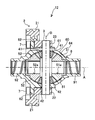
- FIG. 2 is a partial cross-sectional view illustrating a configuration of a differential device 11 according to the first embodiment.
- FIG. It is a partial cross section figure which shows the structure of the differential apparatus 12 of this Embodiment 2.
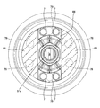
- FIG. It is explanatory drawing which shows a part of differential apparatus of this modification 1.
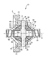
- It is a partial cross section figure which shows the structure of the differential apparatus 13 of this Embodiment 3.
- the present embodiment and the modified embodiment are differential devices that transmit torque from a power source in an automobile or the like, decelerate rotation, and distribute the left and right drive shafts (first drive shaft 91 and second drive shaft 92). *
- the differential device 11 of Embodiment 1 includes a ring gear 2, a pinion shaft 3, pinion gears (first pinion gear 41, second pinion gear 42), and side gears (first gear).
- the ring gear 2 is a helical gear that rotates about the axis A as a rotating shaft by torque from a power source and has teeth 21 formed on the outer periphery. And the inner peripheral part has the engaging part 22 which protrudes to one side of a rotating shaft direction from the tooth
- the case 6 is located on the inner peripheral side of the ring gear 2 and on the inner peripheral side from the engaging portion 22, and has a main body portion 64 and a flange portion (fastening portion) 65.
- the main body 64 houses first and second pinion gears 42 and 42 and first and second side gears 51 and 52, which will be described later.
- the flange portion 65 protrudes from the outer peripheral surface 60 of the main body portion 64 in the diameter increasing direction, and engages with the engaging portion 22 in the rotation direction.
- the flange portion 65 is formed with a plurality of holes 61 into which pins (not shown) are inserted at equal intervals in the circumferential direction, and is engaged with the pinion shaft 3 described later by the pins.
- the case 6 rotates when the ring gear 2 rotates with the axis A, which is the rotation axis of the ring gear 2, as the rotation axis. *
- the pinion shaft 3 is a rotating member having the axis A that is the rotating shaft of the ring gear 2 as a rotating shaft.
- the pinion shaft 3 is fixed to the engaging portion 22 of the ring gear 2 and is also engaged with the case 6.
- the pinion shaft 3 is directly transmitted and rotates integrally with the pinion shaft 3.
- the case 6 rotates as the ring gear 2 and the pinion shaft 3 rotate.
- the first and second pinion gears 41 and 42 are bevel gears whose axis of rotation is an axis B orthogonal to the axis A, and are rotatably supported on the pinion shaft 3.
- the first pinion gear 41 and the second pinion gear 42 are separated and accommodated in the body 64 of the case 6 with the axis A as the symmetry line.
- the first and second pinion gears 41 and 42 can rotate in directions opposite to each other about the axis B as a rotation axis. “Rotation” refers to rotation about the axis B as the rotation axis, and “revolution” refers to rotation due to the rotation of the pinion shaft 3 about the axis A as the rotation axis. *
- the first and second side gears 51 and 52 are bevel gears that mesh with the first and second pinion gears 41 and 42 whose rotation axes are orthogonal to each other.
- One end of the first drive shaft 91 having the axis A as the rotation axis is in the shaft hole 51a of the first side gear 51
- one end of the second drive shaft 92 having the axis A as the rotation axis is the shaft hole 52a in the second side gear 52.
- the first and second side gears 51 and 52 are housed separately in the main body 64 of the case 6 with the axis B as the symmetry line. *
- the pinion shaft 3 is rotated when the ring gear 2 is rotated about the axis A as a rotation axis by the torque transmitted from the power source.
- the case 6 rotates and the first and second pinion gears 41 and 42 revolve.
- the first and second pinion gears 41 and 42 revolve, the first and second drive shafts 91 and 92 that engage with the first and second side gears 51 and 52 that engage with the first and second pinion gears 41 and 42 rotate about the axis A as the rotation axis.
- the torque input to the ring gear 2 is transmitted to the pinion shaft 3, and the first and second side gears 51, 52 are rotated by the revolution of the first and second pinion gears 41, 42.
- the differential device 11 causes the first pinion gear 41 and the second pinion gear 42 to be centered when the rotational speeds of the first drive shaft 91 and the second drive shaft 92 are different, such as when the automobile is turning.
- B By rotating B in opposite directions with B as the rotation axis, it is possible to absorb the difference in rotation speed that occurs between the first drive shaft 91 and the second drive shaft 92.
- the ring gear 2 and the pinion shaft 3 are solidified and rotate integrally, so that the torque input to the ring gear 2 is directly transmitted to the pinion shaft 3.
- torque input to the ring gear is transmitted to the case as a frictional force by a member that engages the ring gear and the case, and the case is rotated by the frictional force so that the torque is applied to the pinion shaft.
- the case 6 is a member for housing the first and second pinion gears 41, 42 and the first and second side gears 51, 52, and is not a member directly involved in torque transmission.
- the ring gear 2 and the case 6 may be assembled to such an extent that they do not come off due to torque. For example, it is not necessary to strongly tighten with high precision in consideration of the torque to be transmitted, or the number of members (bolts and the like) for fastening can be reduced, so that the assembly can be simplified and the cost can be reduced accordingly.
- the strength of the case itself may not be as high as that of the conventional case, and the case can be simplified.
- the simplification can reduce the cost of the case, for example, by making the case cheaper, such as a material that does not have high strength, or by reducing the weight by reducing the thickness of the case.
- Embodiment 2 The differential apparatus 12 of this Embodiment 2 has the fundamentally the same structure and the same effect as the differential apparatus 11 of Embodiment 1. FIG. The following description will focus on the different parts. *
- the ring gear 2 has an inner peripheral portion protruding from the tooth width of the tooth 21 in one direction in the rotation axis direction, and an engagement portion 23 that is fixed to the pinion shaft 3 so as to be integrally rotatable, and a bolt (engagement holding member) 7 is inserted.
- Bolt holes A plurality of bolt holes are formed at equal intervals in the circumferential direction so that the bolts 7 are inserted in the direction of the axis A at the engaging portion 23 portion.
- a flange portion (fastening portion) 62 is formed so that the bolt 7 is inserted at the same position as the bolt hole of the ring gear 2.
- the differential device 12 of the second embodiment since the engagement between the ring gear 2 and the case 6 can be held by the bolt 7, the shaft generated when torque is input to the ring gear 2 that is a helical gear. Since the movement of the ring gear 2 is restricted by the axial force in the direction of the center A, the engagement cannot be released.
- the bolt 7 can also support an axial force.
- the bolt used for engaging the conventional ring gear 7 and the case 6 has been set with a strong fastening force in order to transmit torque to the case 6.
- a strong fastening force is not required and the number of the bolts 7 can be reduced. The weight can be reduced.
- Modification 1 of Embodiment 2 The differential device of Modification 1 basically has the same configuration and the same function and effect as the differential device 12 of Embodiment 2. The following description will focus on the different parts. *
- the case 6 used in the differential device according to the first modification has a flange portion 66 that is a part of the circumferential direction.
- the case 6 and the ring gear 2 are fastened by bolts 7 at four places (upper and lower sides in FIG. 3) of the upper two places and the lower two places.
- 3 indicates the location where the conventional flange portion 69 is present, and the broken line indicates the position of the conventional bolt 79.
- the flange portion can be significantly reduced, so that the case 6 can be reduced in weight. Further, since the number of bolts 7 for fastening is also reduced, the number of parts can be reduced, and the assembling cost is also reduced. *
- the flange part 69 can also be made into the shape which protrudes in not only two circumferential directions but three, four, and a diameter expanding direction. *
- Embodiment 3 The differential apparatus 13 of this Embodiment 3 has the fundamentally the same structure and the same effect as the differential apparatus 11 of Embodiment 1. FIG. The following description will focus on the different parts. *
- the ring gear 2 has an inner peripheral portion that protrudes to one side in the rotation axis direction from the tooth width of the tooth 21, and an engagement portion 24 that is fixed to the pinion shaft 3 so as to be integrally rotatable. And a ring gear spline portion 25.
- a flange portion (fastening portion) 63 that is spline-engaged with the ring gear spline portion 25 is formed on an outer surface portion facing the inner peripheral side of the ring gear 2.
- a snap ring (engagement preventing member) 8 is disposed on one end side of the engaging portion 24 and the flange portion 63 so as to sandwich the outer shape of the case 6.
- the snap ring 8 prevents the ring gear 2 and the case 6 from being disengaged by the ring gear 2 moving in the direction of the axis A due to the axial force generated when torque is input to the ring gear 2. It is installed at a position opposite to the axial force.
- the differential device 13 of the third embodiment since the engagement between the ring gear 2 and the case 6 can be held by the snap ring 8, it is generated when torque is input to the ring gear 2 that is a helical gear. Disengagement can be prevented by the axial force in the direction of the axis A.
- the snap ring 8 can also support an axial force.
- the bolt used to engage the conventional ring gear 2 and the case 6 has been set with a strong fastening force in order to transmit the torque to the case 6 as a frictional force.
- the differential device 13 since the torque input to the ring gear 2 is transmitted to the pinion shaft 3 without passing through the case 6, it is not necessary to strongly fasten the ring gear 2 and the case 6 with bolts. Therefore, since the number of bolts can be reduced and there is no need to strongly tighten the bolts, the assembling cost related to the reduction in the number of components and strong fastening can be reduced.
- the present invention is not limited to the above embodiment.
- the engaging portions 22, 23, and 24 protrude in the axial direction, but the outer peripheral teeth 21 are also extended in the axial direction by a length necessary to engage with the pinion shaft 3.
- Different shapes may be used.
Landscapes
- Engineering & Computer Science (AREA)
- General Engineering & Computer Science (AREA)
- Mechanical Engineering (AREA)
- Retarders (AREA)
Priority Applications (3)
| Application Number | Priority Date | Filing Date | Title |
|---|---|---|---|
| EP10838895.0A EP2518370A4 (en) | 2009-12-22 | 2010-12-08 | DIFFERENTIAL DEVICE |
| US13/514,456 US20120244986A1 (en) | 2009-12-22 | 2010-12-08 | Differential apparatus |
| CN2010800582178A CN102667251A (zh) | 2009-12-22 | 2010-12-08 | 差速器装置 |
Applications Claiming Priority (2)
| Application Number | Priority Date | Filing Date | Title |
|---|---|---|---|
| JP2009-290628 | 2009-12-22 | ||
| JP2009290628A JP4902727B2 (ja) | 2009-12-22 | 2009-12-22 | ディファレンシャル装置 |
Publications (1)
| Publication Number | Publication Date |
|---|---|
| WO2011077655A1 true WO2011077655A1 (ja) | 2011-06-30 |
Family
ID=44195209
Family Applications (1)
| Application Number | Title | Priority Date | Filing Date |
|---|---|---|---|
| PCT/JP2010/007146 Ceased WO2011077655A1 (ja) | 2009-12-22 | 2010-12-08 | ディファレンシャル装置 |
Country Status (5)
| Country | Link |
|---|---|
| US (1) | US20120244986A1 (enExample) |
| EP (1) | EP2518370A4 (enExample) |
| JP (1) | JP4902727B2 (enExample) |
| CN (1) | CN102667251A (enExample) |
| WO (1) | WO2011077655A1 (enExample) |
Families Citing this family (4)
| Publication number | Priority date | Publication date | Assignee | Title |
|---|---|---|---|---|
| JP6189745B2 (ja) * | 2013-12-27 | 2017-08-30 | 武蔵精密工業株式会社 | 差動装置の製造方法 |
| JP6536492B2 (ja) * | 2016-06-08 | 2019-07-03 | トヨタ自動車株式会社 | ディファレンシャル用リングギヤ |
| JP6847874B2 (ja) | 2018-01-18 | 2021-03-24 | 武蔵精密工業株式会社 | 差動装置 |
| DE102022127536A1 (de) * | 2022-10-19 | 2024-04-25 | Audi Aktiengesellschaft | Kegelraddifferentialgetriebe für ein Kraftfahrzeug sowie Verfahren zum Herstellen eines Kegelraddifferentialgetriebes |
Citations (5)
| Publication number | Priority date | Publication date | Assignee | Title |
|---|---|---|---|---|
| JPS5438027A (en) * | 1977-08-31 | 1979-03-22 | Asano Haguruma Kousakushiyo Kk | Differential gear for car |
| JPH0196554U (enExample) * | 1987-12-19 | 1989-06-27 | ||
| JPH0658378A (ja) | 1992-08-04 | 1994-03-01 | Tochigi Fuji Ind Co Ltd | デファレンシャル装置 |
| JPH094694A (ja) * | 1995-06-19 | 1997-01-07 | Honda Motor Co Ltd | 差動装置 |
| JPH10250389A (ja) * | 1997-03-11 | 1998-09-22 | Nissan Motor Co Ltd | 終減速機 |
Family Cites Families (32)
| Publication number | Priority date | Publication date | Assignee | Title |
|---|---|---|---|---|
| US1421834A (en) * | 1921-03-09 | 1922-07-04 | Advance Rumely Co | Differential |
| US1810194A (en) * | 1928-09-27 | 1931-06-16 | Columbia Axle Company | Differential mechanism |
| US1987716A (en) * | 1933-09-25 | 1935-01-15 | Chrysler Corp | Torque transmitting apparatus |
| US2431272A (en) * | 1944-02-22 | 1947-11-18 | Fischer Ag Georg | Self-locking equalizing drive |
| US2408926A (en) * | 1944-07-15 | 1946-10-08 | Gen Motors Corp | Drive axle |
| US2546969A (en) * | 1947-07-24 | 1951-04-03 | Timken Axle Co Detroit | Collars to prevent broken axle shaft fragments entering axle center section |
| GB1252520A (enExample) * | 1969-10-18 | 1971-11-03 | ||
| US4334719A (en) * | 1977-11-07 | 1982-06-15 | The J. B. Foote Foundry Co. | Transaxle |
| JPH0196554A (ja) * | 1987-10-08 | 1989-04-14 | Kubota Ltd | サクションロール亀裂検出用治具 |
| DE4042174A1 (de) * | 1990-12-29 | 1992-07-02 | Schmetz Roland Dipl Ing Dipl W | Differentialgetriebe |
| DE4313322C2 (de) * | 1993-04-23 | 2001-08-02 | Porsche Ag | Differential für den Achsantrieb eines Kraftfahrzeuges |
| EP0683333B1 (de) * | 1994-05-18 | 1997-10-01 | Dr.Ing.h.c. F. Porsche Aktiengesellschaft | Differential für den Achsantrieb eines Kraftfahrzeuges |
| US5980416A (en) * | 1997-08-06 | 1999-11-09 | Sven B. Gafvert | Differential for a vehicle |
| US6056663A (en) * | 1999-04-30 | 2000-05-02 | Dana Corporation | Short span differential gear assembly |
| US6652408B2 (en) * | 2001-12-11 | 2003-11-25 | Visteon Global Technologies, Inc. | Vehicular differential with ring gear directly loading the differential pin |
| US6702707B2 (en) * | 2002-01-31 | 2004-03-09 | Visteon Global Technologies, Inc. | Differential assembly |
| US6623396B2 (en) * | 2002-01-31 | 2003-09-23 | Visteon Global Technologies, Inc. | Differential gear assembly |
| US6616565B1 (en) * | 2002-03-19 | 2003-09-09 | Yao-Yu Chen | Differential gear designed for use in light-duty motor vehicles |
| US6743138B2 (en) * | 2002-07-23 | 2004-06-01 | Visteon Global Technologies, Inc. | Compact differential housing assembly |
| DE10234035B4 (de) * | 2002-07-26 | 2004-09-16 | Gkn Driveline International Gmbh | Differentialgetriebe mit leichtem Differentialträger |
| US6849021B2 (en) * | 2003-02-19 | 2005-02-01 | Visteon Global Technologies, Inc. | Limited slip differential |
| US7077778B1 (en) * | 2003-12-03 | 2006-07-18 | Koji Irikura | Bull gear of differential gear assembly |
| US7393301B2 (en) * | 2005-08-05 | 2008-07-01 | Dana Heavy Vehicle Systems Group, Llc | Gear driven direct differential cross |
| AT8782U1 (de) * | 2005-09-27 | 2006-12-15 | Engineering Ct Steyr Gmbh & Co | Triebachse für ein leicht-fahrzeug |
| JP2007218423A (ja) * | 2006-01-19 | 2007-08-30 | Gkn ドライブライン トルクテクノロジー株式会社 | デファレンシャル装置 |
| DE102008017221A1 (de) * | 2007-04-05 | 2008-10-09 | Neumayer Tekfor Holding Gmbh | Mit einem Antriebsrad versehenes Differential |
| US7695392B2 (en) * | 2007-07-10 | 2010-04-13 | Ford Global Technologies, Llc | Differential mechanism assembly |
| JP5072099B2 (ja) * | 2008-02-27 | 2012-11-14 | 武蔵精密工業株式会社 | ディファレンシャル装置 |
| US20090258750A1 (en) * | 2008-04-15 | 2009-10-15 | Ziech James F | Vehicle differential |
| US8043188B2 (en) * | 2008-09-04 | 2011-10-25 | Dana Heavy Vehicle Systems Group, Llc | Spider-less vehicle differential |
| CN102003499B (zh) * | 2009-08-31 | 2013-11-20 | 鸿富锦精密工业(深圳)有限公司 | 行星齿轮传动机构 |
| EP2473761B1 (de) * | 2009-09-02 | 2015-07-01 | Amtek Tekfor Holding GmbH | Differenzial |
-
2009
- 2009-12-22 JP JP2009290628A patent/JP4902727B2/ja not_active Expired - Fee Related
-
2010
- 2010-12-08 WO PCT/JP2010/007146 patent/WO2011077655A1/ja not_active Ceased
- 2010-12-08 US US13/514,456 patent/US20120244986A1/en not_active Abandoned
- 2010-12-08 CN CN2010800582178A patent/CN102667251A/zh active Pending
- 2010-12-08 EP EP10838895.0A patent/EP2518370A4/en not_active Withdrawn
Patent Citations (5)
| Publication number | Priority date | Publication date | Assignee | Title |
|---|---|---|---|---|
| JPS5438027A (en) * | 1977-08-31 | 1979-03-22 | Asano Haguruma Kousakushiyo Kk | Differential gear for car |
| JPH0196554U (enExample) * | 1987-12-19 | 1989-06-27 | ||
| JPH0658378A (ja) | 1992-08-04 | 1994-03-01 | Tochigi Fuji Ind Co Ltd | デファレンシャル装置 |
| JPH094694A (ja) * | 1995-06-19 | 1997-01-07 | Honda Motor Co Ltd | 差動装置 |
| JPH10250389A (ja) * | 1997-03-11 | 1998-09-22 | Nissan Motor Co Ltd | 終減速機 |
Non-Patent Citations (1)
| Title |
|---|
| See also references of EP2518370A4 * |
Also Published As
| Publication number | Publication date |
|---|---|
| CN102667251A (zh) | 2012-09-12 |
| EP2518370A1 (en) | 2012-10-31 |
| US20120244986A1 (en) | 2012-09-27 |
| JP4902727B2 (ja) | 2012-03-21 |
| EP2518370A4 (en) | 2013-06-12 |
| JP2011132977A (ja) | 2011-07-07 |
Similar Documents
| Publication | Publication Date | Title |
|---|---|---|
| US11015683B2 (en) | Vehicle driving device | |
| JP6194436B1 (ja) | 遊星歯車機構を組み合わせた回転伝達装置 | |
| US11027616B2 (en) | Vehicle driving device | |
| JP4902727B2 (ja) | ディファレンシャル装置 | |
| EP3663611B1 (en) | Drive device for vehicle | |
| JP2011132977A5 (enExample) | ||
| JP2002235832A (ja) | 減速機付き差動装置 | |
| JP6856140B2 (ja) | 車両用駆動装置 | |
| JP5440543B2 (ja) | 変速装置 | |
| JP2021162052A (ja) | 車両用駆動伝達装置 | |
| JP4982599B2 (ja) | ディファレンシャル装置 | |
| JP5146742B2 (ja) | 差動装置 | |
| JP6356830B2 (ja) | 遊星歯車組を備える車両の動力伝達装置(ptu) | |
| WO2005115791A1 (en) | Limited slip differential device suitable for downsizing | |
| JP2019074207A (ja) | 車両用駆動装置 | |
| JP2015110962A (ja) | ギヤカップリング及びこれを備えた車両用ホイール駆動装置 | |
| JP2010180976A (ja) | デファレンシャル装置 | |
| JP2005344745A (ja) | 車両用駆動力伝達装置 | |
| JP2019105331A (ja) | 電動駆動装置 | |
| JP2018031404A (ja) | 差動装置 | |
| JPH0211770B2 (enExample) | ||
| WO2023048134A1 (ja) | 車両用駆動装置 | |
| JP2023081113A (ja) | 動力伝達装置 | |
| JP2010144911A (ja) | 車両用差動歯車装置 | |
| JP2019074206A (ja) | 車両用駆動装置 |
Legal Events
| Date | Code | Title | Description |
|---|---|---|---|
| WWE | Wipo information: entry into national phase |
Ref document number: 201080058217.8 Country of ref document: CN |
|
| 121 | Ep: the epo has been informed by wipo that ep was designated in this application |
Ref document number: 10838895 Country of ref document: EP Kind code of ref document: A1 |
|
| WWE | Wipo information: entry into national phase |
Ref document number: 13514456 Country of ref document: US |
|
| WWE | Wipo information: entry into national phase |
Ref document number: 2010838895 Country of ref document: EP |
|
| NENP | Non-entry into the national phase |
Ref country code: DE |