WO2011077655A1 - Differential device - Google Patents
Differential device Download PDFInfo
- Publication number
- WO2011077655A1 WO2011077655A1 PCT/JP2010/007146 JP2010007146W WO2011077655A1 WO 2011077655 A1 WO2011077655 A1 WO 2011077655A1 JP 2010007146 W JP2010007146 W JP 2010007146W WO 2011077655 A1 WO2011077655 A1 WO 2011077655A1
- Authority
- WO
- WIPO (PCT)
- Prior art keywords
- case
- ring gear
- gear
- pinion
- pinion shaft
- Prior art date
Links
Images

Classifications
-
- F—MECHANICAL ENGINEERING; LIGHTING; HEATING; WEAPONS; BLASTING
- F16—ENGINEERING ELEMENTS AND UNITS; GENERAL MEASURES FOR PRODUCING AND MAINTAINING EFFECTIVE FUNCTIONING OF MACHINES OR INSTALLATIONS; THERMAL INSULATION IN GENERAL
- F16H—GEARING
- F16H48/00—Differential gearings
- F16H48/06—Differential gearings with gears having orbital motion
- F16H48/08—Differential gearings with gears having orbital motion comprising bevel gears
-
- F—MECHANICAL ENGINEERING; LIGHTING; HEATING; WEAPONS; BLASTING
- F16—ENGINEERING ELEMENTS AND UNITS; GENERAL MEASURES FOR PRODUCING AND MAINTAINING EFFECTIVE FUNCTIONING OF MACHINES OR INSTALLATIONS; THERMAL INSULATION IN GENERAL
- F16H—GEARING
- F16H48/00—Differential gearings
- F16H48/38—Constructional details
- F16H2048/385—Constructional details of the ring or crown gear
-
- F—MECHANICAL ENGINEERING; LIGHTING; HEATING; WEAPONS; BLASTING
- F16—ENGINEERING ELEMENTS AND UNITS; GENERAL MEASURES FOR PRODUCING AND MAINTAINING EFFECTIVE FUNCTIONING OF MACHINES OR INSTALLATIONS; THERMAL INSULATION IN GENERAL
- F16H—GEARING
- F16H48/00—Differential gearings
- F16H48/38—Constructional details
- F16H48/40—Constructional details characterised by features of the rotating cases
Definitions
- the present invention relates to a differential apparatus.
- the differential apparatus uses a ring gear (11), a case (3), a pinion shaft (21), a pinion gear (19), and side gears (15, 17) to generate torque from a power source such as an engine as disclosed in Patent Document 1.
- a power source such as an engine as disclosed in Patent Document 1.
- the ring gear (11) is assembled to the flange (9) of the case (3) with a bolt (13), and the pinion shaft (21) is assembled to the case (3).
- the pinion gear (19) is rotatably supported by the pinion shaft (21), and the pinion gear (19) and the side gears (15, 17) are engaged with each other.
- the differential device described above transmits the torque input to the ring gear to the case by the frictional force between the ring gear and the flange generated by the axial force of the bolt, the assembly of the bolts involved in torque transmission is highly accurate. Costly, such as tightening strongly. Further, since the transmitted torque is transmitted through the case, the case also requires a strength that can withstand the transmitted torque and frictional force, so that there is a problem that costs are increased. *
- This invention is made
- the structural features of the invention according to claim 1 for solving the above-described problems are: a ring gear that rotates when torque from a power source is input; and a pinion shaft that engages in the rotation direction of the ring gear and rotates integrally.
- a pinion gear rotatably supported on the pinion shaft, a side gear meshing with the pinion gear, and a case that rotates integrally with the ring gear and the pinion shaft and accommodates the pinion gear and the side gear inside. That is.
- the structural feature of the invention according to claim 2 for solving the above-mentioned problems is that a ring gear that rotates by receiving torque from a power source, a case that can rotate integrally with the ring gear, and a rotation that integrally rotates with the case A pinion shaft that engages with the ring gear and directly transmits the torque without passing through the case and rotates integrally with the ring gear; and a pinion gear that is housed in the case and rotatably supported by the pinion shaft And a side gear housed in the case and meshing with the pinion gear.
- a structural feature of the invention according to claim 3 is that in claim 1 or 2, the invention has an engagement holding member that holds the engagement between the ring gear and the case by limiting the movement of the ring gear in the axial direction. It is. *
- the case includes a main body portion in which the pinion gear and the side gear are housed, A part of the circumferential direction protrudes from the outer peripheral surface in the diameter increasing direction, and the ring gear and the case have a fastening portion fastened in the rotational direction.
- the torque input to the ring gear is directly transmitted to the pinion shaft.
- torque input to the ring gear is transmitted to the case as a frictional force by a member that engages the ring gear and the case, and the case is rotated by the frictional force so that the torque is applied to the pinion shaft.
- the case is a member for housing the pinion gear and the side gear, and rotates integrally with the ring gear and the pinion shaft, but is not a member directly involved in torque transmission.
- the engagement holding member is a member that holds the engagement between the ring gear and the case in the axial direction of the ring gear, the ring gear is moved by the axial force generated by the torque input to the ring gear. The engagement between the ring gear and the case is maintained.
- the case is fastened to the ring gear at a fastening portion that partially protrudes in the diameter increasing direction from the outer peripheral surface of the main body portion in which the pinion gear and the side gear are accommodated.
- the ring gear is solidified by a flange portion protruding over the entire circumference. According to the differential device of the present invention, a part of the circumferential direction protrudes, and the number of fastening portions (flange portions) can be greatly reduced, so that the case can be reduced in weight.
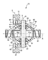
- FIG. 2 is a partial cross-sectional view illustrating a configuration of a differential device 11 according to the first embodiment.
- FIG. It is a partial cross section figure which shows the structure of the differential apparatus 12 of this Embodiment 2.
- FIG. It is explanatory drawing which shows a part of differential apparatus of this modification 1.
- It is a partial cross section figure which shows the structure of the differential apparatus 13 of this Embodiment 3.
- the present embodiment and the modified embodiment are differential devices that transmit torque from a power source in an automobile or the like, decelerate rotation, and distribute the left and right drive shafts (first drive shaft 91 and second drive shaft 92). *
- the differential device 11 of Embodiment 1 includes a ring gear 2, a pinion shaft 3, pinion gears (first pinion gear 41, second pinion gear 42), and side gears (first gear).
- the ring gear 2 is a helical gear that rotates about the axis A as a rotating shaft by torque from a power source and has teeth 21 formed on the outer periphery. And the inner peripheral part has the engaging part 22 which protrudes to one side of a rotating shaft direction from the tooth
- the case 6 is located on the inner peripheral side of the ring gear 2 and on the inner peripheral side from the engaging portion 22, and has a main body portion 64 and a flange portion (fastening portion) 65.
- the main body 64 houses first and second pinion gears 42 and 42 and first and second side gears 51 and 52, which will be described later.
- the flange portion 65 protrudes from the outer peripheral surface 60 of the main body portion 64 in the diameter increasing direction, and engages with the engaging portion 22 in the rotation direction.
- the flange portion 65 is formed with a plurality of holes 61 into which pins (not shown) are inserted at equal intervals in the circumferential direction, and is engaged with the pinion shaft 3 described later by the pins.
- the case 6 rotates when the ring gear 2 rotates with the axis A, which is the rotation axis of the ring gear 2, as the rotation axis. *
- the pinion shaft 3 is a rotating member having the axis A that is the rotating shaft of the ring gear 2 as a rotating shaft.
- the pinion shaft 3 is fixed to the engaging portion 22 of the ring gear 2 and is also engaged with the case 6.
- the pinion shaft 3 is directly transmitted and rotates integrally with the pinion shaft 3.
- the case 6 rotates as the ring gear 2 and the pinion shaft 3 rotate.
- the first and second pinion gears 41 and 42 are bevel gears whose axis of rotation is an axis B orthogonal to the axis A, and are rotatably supported on the pinion shaft 3.
- the first pinion gear 41 and the second pinion gear 42 are separated and accommodated in the body 64 of the case 6 with the axis A as the symmetry line.
- the first and second pinion gears 41 and 42 can rotate in directions opposite to each other about the axis B as a rotation axis. “Rotation” refers to rotation about the axis B as the rotation axis, and “revolution” refers to rotation due to the rotation of the pinion shaft 3 about the axis A as the rotation axis. *
- the first and second side gears 51 and 52 are bevel gears that mesh with the first and second pinion gears 41 and 42 whose rotation axes are orthogonal to each other.
- One end of the first drive shaft 91 having the axis A as the rotation axis is in the shaft hole 51a of the first side gear 51
- one end of the second drive shaft 92 having the axis A as the rotation axis is the shaft hole 52a in the second side gear 52.
- the first and second side gears 51 and 52 are housed separately in the main body 64 of the case 6 with the axis B as the symmetry line. *
- the pinion shaft 3 is rotated when the ring gear 2 is rotated about the axis A as a rotation axis by the torque transmitted from the power source.
- the case 6 rotates and the first and second pinion gears 41 and 42 revolve.
- the first and second pinion gears 41 and 42 revolve, the first and second drive shafts 91 and 92 that engage with the first and second side gears 51 and 52 that engage with the first and second pinion gears 41 and 42 rotate about the axis A as the rotation axis.
- the torque input to the ring gear 2 is transmitted to the pinion shaft 3, and the first and second side gears 51, 52 are rotated by the revolution of the first and second pinion gears 41, 42.
- the differential device 11 causes the first pinion gear 41 and the second pinion gear 42 to be centered when the rotational speeds of the first drive shaft 91 and the second drive shaft 92 are different, such as when the automobile is turning.
- B By rotating B in opposite directions with B as the rotation axis, it is possible to absorb the difference in rotation speed that occurs between the first drive shaft 91 and the second drive shaft 92.
- the ring gear 2 and the pinion shaft 3 are solidified and rotate integrally, so that the torque input to the ring gear 2 is directly transmitted to the pinion shaft 3.
- torque input to the ring gear is transmitted to the case as a frictional force by a member that engages the ring gear and the case, and the case is rotated by the frictional force so that the torque is applied to the pinion shaft.
- the case 6 is a member for housing the first and second pinion gears 41, 42 and the first and second side gears 51, 52, and is not a member directly involved in torque transmission.
- the ring gear 2 and the case 6 may be assembled to such an extent that they do not come off due to torque. For example, it is not necessary to strongly tighten with high precision in consideration of the torque to be transmitted, or the number of members (bolts and the like) for fastening can be reduced, so that the assembly can be simplified and the cost can be reduced accordingly.
- the strength of the case itself may not be as high as that of the conventional case, and the case can be simplified.
- the simplification can reduce the cost of the case, for example, by making the case cheaper, such as a material that does not have high strength, or by reducing the weight by reducing the thickness of the case.
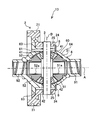
- Embodiment 2 The differential apparatus 12 of this Embodiment 2 has the fundamentally the same structure and the same effect as the differential apparatus 11 of Embodiment 1. FIG. The following description will focus on the different parts. *
- the ring gear 2 has an inner peripheral portion protruding from the tooth width of the tooth 21 in one direction in the rotation axis direction, and an engagement portion 23 that is fixed to the pinion shaft 3 so as to be integrally rotatable, and a bolt (engagement holding member) 7 is inserted.
- Bolt holes A plurality of bolt holes are formed at equal intervals in the circumferential direction so that the bolts 7 are inserted in the direction of the axis A at the engaging portion 23 portion.
- a flange portion (fastening portion) 62 is formed so that the bolt 7 is inserted at the same position as the bolt hole of the ring gear 2.
- the differential device 12 of the second embodiment since the engagement between the ring gear 2 and the case 6 can be held by the bolt 7, the shaft generated when torque is input to the ring gear 2 that is a helical gear. Since the movement of the ring gear 2 is restricted by the axial force in the direction of the center A, the engagement cannot be released.
- the bolt 7 can also support an axial force.
- the bolt used for engaging the conventional ring gear 7 and the case 6 has been set with a strong fastening force in order to transmit torque to the case 6.
- a strong fastening force is not required and the number of the bolts 7 can be reduced. The weight can be reduced.
- Modification 1 of Embodiment 2 The differential device of Modification 1 basically has the same configuration and the same function and effect as the differential device 12 of Embodiment 2. The following description will focus on the different parts. *
- the case 6 used in the differential device according to the first modification has a flange portion 66 that is a part of the circumferential direction.
- the case 6 and the ring gear 2 are fastened by bolts 7 at four places (upper and lower sides in FIG. 3) of the upper two places and the lower two places.
- 3 indicates the location where the conventional flange portion 69 is present, and the broken line indicates the position of the conventional bolt 79.
- the flange portion can be significantly reduced, so that the case 6 can be reduced in weight. Further, since the number of bolts 7 for fastening is also reduced, the number of parts can be reduced, and the assembling cost is also reduced. *
- the flange part 69 can also be made into the shape which protrudes in not only two circumferential directions but three, four, and a diameter expanding direction. *
- Embodiment 3 The differential apparatus 13 of this Embodiment 3 has the fundamentally the same structure and the same effect as the differential apparatus 11 of Embodiment 1. FIG. The following description will focus on the different parts. *
- the ring gear 2 has an inner peripheral portion that protrudes to one side in the rotation axis direction from the tooth width of the tooth 21, and an engagement portion 24 that is fixed to the pinion shaft 3 so as to be integrally rotatable. And a ring gear spline portion 25.
- a flange portion (fastening portion) 63 that is spline-engaged with the ring gear spline portion 25 is formed on an outer surface portion facing the inner peripheral side of the ring gear 2.
- a snap ring (engagement preventing member) 8 is disposed on one end side of the engaging portion 24 and the flange portion 63 so as to sandwich the outer shape of the case 6.
- the snap ring 8 prevents the ring gear 2 and the case 6 from being disengaged by the ring gear 2 moving in the direction of the axis A due to the axial force generated when torque is input to the ring gear 2. It is installed at a position opposite to the axial force.
- the differential device 13 of the third embodiment since the engagement between the ring gear 2 and the case 6 can be held by the snap ring 8, it is generated when torque is input to the ring gear 2 that is a helical gear. Disengagement can be prevented by the axial force in the direction of the axis A.
- the snap ring 8 can also support an axial force.
- the bolt used to engage the conventional ring gear 2 and the case 6 has been set with a strong fastening force in order to transmit the torque to the case 6 as a frictional force.
- the differential device 13 since the torque input to the ring gear 2 is transmitted to the pinion shaft 3 without passing through the case 6, it is not necessary to strongly fasten the ring gear 2 and the case 6 with bolts. Therefore, since the number of bolts can be reduced and there is no need to strongly tighten the bolts, the assembling cost related to the reduction in the number of components and strong fastening can be reduced.
- the present invention is not limited to the above embodiment.
- the engaging portions 22, 23, and 24 protrude in the axial direction, but the outer peripheral teeth 21 are also extended in the axial direction by a length necessary to engage with the pinion shaft 3.
- Different shapes may be used.
Abstract
Provided is a differential device (11) characterized by having: a ring gear (2) that rotates as torque is inputted from a power source; a pinion shaft (3) that engages with the ring gear (2) and rotates as a single unit therewith, in the same direction; pinion gears (41, 42) that are rotatably supported by the pinion shaft (3); side gears (51, 52) that mesh with the pinion gears (41, 42); and a case (6) that rotates as a single unit with the ring gear (2) and the pinion shaft (3). The pinion gears (41, 42) and the side gears (51, 52) are contained inside the case (6).
Description
本発明は、ディファレンシャル装置に関する。
The present invention relates to a differential apparatus.
自動車などの車両に用いられるディファレンシャル装置がある。ディファレンシャル装置は、例えば、特許文献1に示されるようなエンジン等の動力源からのトルクをリングギヤ(11)、ケース(3)、ピニオンシャフト(21)、ピニオンギヤ(19)、サイドギヤ(15,17)と順に伝達するものが知られている。リングギヤ(11)はケース(3)のフランジ部(9)にボルト(13)で組み付けられており、ピニオンシャフト(21)はケース(3)に組み付けられている。そして、ピニオンギヤ(19)はピニオンシャフト(21)に回転自在に軸支されており、ピニオンギヤ(19)とサイドギヤ(15,17)とが噛合している。
特開平6-58378号公報
There are differential devices used in vehicles such as automobiles. The differential apparatus, for example, uses a ring gear (11), a case (3), a pinion shaft (21), a pinion gear (19), and side gears (15, 17) to generate torque from a power source such as an engine as disclosed in Patent Document 1. Those that communicate in order are known. The ring gear (11) is assembled to the flange (9) of the case (3) with a bolt (13), and the pinion shaft (21) is assembled to the case (3). The pinion gear (19) is rotatably supported by the pinion shaft (21), and the pinion gear (19) and the side gears (15, 17) are engaged with each other.
JP-A-6-58378
上記したディファレンシャル装置は、リングギヤに入力されたトルクをボルトの軸力によって発生させたリングギヤとフランジ部との間の摩擦力によってケースに伝達するため、トルク伝達に関与するボルトの組み付けは、高精度で強く締結する等、コストが掛かる。また、伝達されるトルクは、ケースを介して伝えられるため、ケースも伝達されるトルクや摩擦力に耐え得る強度を必要とするためコストが掛かるという問題がある。
Since the differential device described above transmits the torque input to the ring gear to the case by the frictional force between the ring gear and the flange generated by the axial force of the bolt, the assembly of the bolts involved in torque transmission is highly accurate. Costly, such as tightening strongly. Further, since the transmitted torque is transmitted through the case, the case also requires a strength that can withstand the transmitted torque and frictional force, so that there is a problem that costs are increased. *
本発明は、上記課題に鑑みてなされたもので、ボルトの組み付けの簡略化やケースを簡略化することができるディファレンシャル装置を提供することを解決すべき課題とする。
This invention is made | formed in view of the said subject, and makes it the subject which should be solved to provide the differential apparatus which can simplify the assembly | attachment of a volt | bolt and a case.
上記課題を解決するための請求項1に係る発明の構成上の特徴は、動力源からのトルクが入力されて回転するリングギヤと、 前記リングギヤとその回転方向に係合し一体回転するピニオンシャフトと、 前記ピニオンシャフトに回転自在に軸支されるピニオンギヤと、 前記ピニオンギヤと噛合するサイドギヤと、 前記リングギヤ及び前記ピニオンシャフトと一体回転し、前記ピニオンギヤと前記サイドギヤとを内部に収容するケースと、 を有することである。
The structural features of the invention according to claim 1 for solving the above-described problems are: a ring gear that rotates when torque from a power source is input; and a pinion shaft that engages in the rotation direction of the ring gear and rotates integrally. A pinion gear rotatably supported on the pinion shaft, a side gear meshing with the pinion gear, and a case that rotates integrally with the ring gear and the pinion shaft and accommodates the pinion gear and the side gear inside. That is. *
また上記課題を解決するための請求項2に係る発明の構成上の特徴は、動力源からのトルクが入力されて回転するリングギヤと、 前記リングギヤと一体回転可能なケースと、 前記ケースと一体回転可能で、前記リングギヤと係合し、前記トルクが前記ケースを介さず直接伝達されて前記リングギヤと一体回転するピニオンシャフトと、 前記ケースに収容され、前記ピニオンシャフトに回転自在に軸支されるピニオンギヤと、 前記ケースに収容され、前記ピニオンギヤと噛合するサイドギヤと、 を有することである。
Further, the structural feature of the invention according to claim 2 for solving the above-mentioned problems is that a ring gear that rotates by receiving torque from a power source, a case that can rotate integrally with the ring gear, and a rotation that integrally rotates with the case A pinion shaft that engages with the ring gear and directly transmits the torque without passing through the case and rotates integrally with the ring gear; and a pinion gear that is housed in the case and rotatably supported by the pinion shaft And a side gear housed in the case and meshing with the pinion gear. *
また請求項3に係る発明の構成上の特徴は、請求項1又は2において、前記リングギヤのその軸方向における移動を制限してリングギヤとケースとの係合を保持する係合保持部材を有することである。
A structural feature of the invention according to claim 3 is that in claim 1 or 2, the invention has an engagement holding member that holds the engagement between the ring gear and the case by limiting the movement of the ring gear in the axial direction. It is. *
また請求項4に係る発明の構成上の特徴は、請求項1~3の何れか1項において、前記ケースは、前記ピニオンギヤと前記サイドギヤとが内部に収容される本体部と、前記本体部の外周面から周方向の一部が拡径方向に突出し、前記リングギヤと前記ケースとが回転方向で締結する締結部とを有することである。
According to a fourth aspect of the present invention, there is provided a structural feature according to any one of the first to third aspects, wherein the case includes a main body portion in which the pinion gear and the side gear are housed, A part of the circumferential direction protrudes from the outer peripheral surface in the diameter increasing direction, and the ring gear and the case have a fastening portion fastened in the rotational direction.
請求項1に係る発明においては、リングギヤとピニオンシャフトとが回転方向に係合して一体回転するため、リングギヤに入力されたトルクが直接ピニオンシャフトに伝達される。通常、このような構成のディファレンシャル装置は、リングギヤとケースとを係合する部材によってリングギヤに入力されたトルクが摩擦力としてケースに伝達され、摩擦力によりケースが回転することでピニオンシャフトにトルクが伝達される。しかし、本願のディファレンシャル装置は、ケースはピニオンギヤとサイドギヤとを収容するための部材であり、リングギヤ及びピニオンシャフトと一体回転するが、トルクの伝達に直接関与する部材ではない。そのため、リングギヤとケースとがトルクにより外れたりしないように組み付ければ良く、締結するための部材も減らすことができる等、組み付けが簡略化できる。また、ケースに大きな荷重が加わらないため、ケース自体の強度も従来ほど高いものでなくても良く、簡略化可能でケースの重量を削減したり、ケースの費用を低減したりすることができる。
In the invention according to claim 1, since the ring gear and the pinion shaft are engaged with each other in the rotation direction and rotate integrally, the torque input to the ring gear is directly transmitted to the pinion shaft. Normally, in the differential device having such a configuration, torque input to the ring gear is transmitted to the case as a frictional force by a member that engages the ring gear and the case, and the case is rotated by the frictional force so that the torque is applied to the pinion shaft. Communicated. However, in the differential device of the present application, the case is a member for housing the pinion gear and the side gear, and rotates integrally with the ring gear and the pinion shaft, but is not a member directly involved in torque transmission. Therefore, it is only necessary to assemble so that the ring gear and the case do not come off due to torque, and the assembly can be simplified, for example, the number of members for fastening can be reduced. In addition, since a large load is not applied to the case, the strength of the case itself may not be as high as that of the conventional case, and simplification is possible and the weight of the case can be reduced or the cost of the case can be reduced. *
請求項2に係る発明においては、リングギヤに入力されたトルクがケースを介さずにピニオンシャフトに直接伝達されるため、リングギヤとケースとの間で発生する摩擦力により、ケースが回転してピニオンシャフトが回転するものではない。そのため、リングギヤとケースとを締結する部材を必要なトルクを伝達できるように高精度で強く締結する必要がないので、組み付けを簡略化できる。また、ケースは、これまで発生していた摩擦力に耐え得る強度を必要としないため、例えば、高強度でない材料や肉薄化等、簡略化することが可能となる。
In the invention according to claim 2, since the torque input to the ring gear is directly transmitted to the pinion shaft without passing through the case, the case rotates by the frictional force generated between the ring gear and the case, and the pinion shaft Does not rotate. For this reason, it is not necessary to fasten the member for fastening the ring gear and the case with high precision so that necessary torque can be transmitted, so that the assembly can be simplified. Moreover, since the case does not require strength that can withstand the frictional force that has been generated, it is possible to simplify the case, for example, by using a material that is not high strength or thinning. *
請求項3に係る発明においては、係合保持部材が、リングギヤの軸方向でリングギヤとケースとの係合を保持する部材であるため、リングギヤに入力されるトルクにより発生する軸力でリングギヤが移動することができず、リングギヤとケースとの係合が保持される。
In the invention according to claim 3, since the engagement holding member is a member that holds the engagement between the ring gear and the case in the axial direction of the ring gear, the ring gear is moved by the axial force generated by the torque input to the ring gear. The engagement between the ring gear and the case is maintained. *
請求項4に係る発明においては、ケースがピニオンギヤと前記サイドギヤとが内部に収容される本体部の外周面から拡径方向に一部突出している締結部でリングギヤと締結する。リングギヤが回転することで伝達される動力を摩擦力として受けピニオンシャフトに伝達するケースでは、全周に渡り突出したフランジ部でリングギヤと固結する。本発明のディファレンシャル装置によれば、周方向の一部が突出しており、締結部(フランジ部)を大幅に削減できるため、ケースが軽量化できる。
In the invention according to claim 4, the case is fastened to the ring gear at a fastening portion that partially protrudes in the diameter increasing direction from the outer peripheral surface of the main body portion in which the pinion gear and the side gear are accommodated. In the case where the power transmitted by the rotation of the ring gear is received as frictional force and transmitted to the pinion shaft, the ring gear is solidified by a flange portion protruding over the entire circumference. According to the differential device of the present invention, a part of the circumferential direction protrudes, and the number of fastening portions (flange portions) can be greatly reduced, so that the case can be reduced in weight.
11,12,13:ディファレンシャル装置、2:リングギヤ、21:歯、22,23,24:係合部、25:リングギヤスプライン部、3:ピニオンシャフト、41、:第1ピニオンギヤ、42:第2ピニオンギヤ、51:第1サイドギヤ、51a、52a:軸穴、52:第2サイドギヤ、6:ケース、60:外周面、61:孔、62,63,65,66:フランジ部(締結部)、64:本体部、63:ケーススプライン部、69:従来のフランジ部、7:ボルト(係合保持部材)、79:従来のボルト、8:スナップリング(係合保持部材)、91:第1駆動軸、92:第2駆動軸。
11, 12, 13: Differential device, 2: Ring gear, 21: Teeth, 22, 23, 24: Engagement part, 25: Ring gear spline part, 3: Pinion shaft, 41: First pinion gear, 42: Second pinion gear 51: first side gear, 51a, 52a: shaft hole, 52: second side gear, 6: case, 60: outer peripheral surface, 61: hole, 62, 63, 65, 66: flange portion (fastening portion), 64: Body part 63: Case spline part 69: Conventional flange part 7: Bolt (engagement holding member) 79: Conventional bolt 8: Snap ring (engagement holding member) 91: First drive shaft 92: Second drive shaft.
本発明の代表的な実施形態を図1~図4を参照して説明する。本実施形態及び変形形態は、自動車等において動力源からのトルクが伝達され、回転を減速し、左右の駆動軸(第1駆動軸91、第2駆動軸92)に分配するディファレンシャル装置である。
A representative embodiment of the present invention will be described with reference to FIGS. The present embodiment and the modified embodiment are differential devices that transmit torque from a power source in an automobile or the like, decelerate rotation, and distribute the left and right drive shafts (first drive shaft 91 and second drive shaft 92). *
(実施形態1) 本実施形態1のディファレンシャル装置11は、図1に示されるように、リングギヤ2と、ピニオンシャフト3と、ピニオンギヤ(第1ピニオンギヤ41、第2ピニオンギヤ42)と、サイドギヤ(第1サイドギヤ51、第2サイドギヤ52)と、ケース6とを有する。
(Embodiment 1) As shown in FIG. 1, the differential device 11 of Embodiment 1 includes a ring gear 2, a pinion shaft 3, pinion gears (first pinion gear 41, second pinion gear 42), and side gears (first gear). A side gear 51, a second side gear 52), and a case 6. *
リングギヤ2は、動力源からのトルクにより軸心Aを回転軸として回転し、外周に歯21が形成されるはすば歯車である。そして、内周部分が歯21の歯幅より回転軸方向の一方に突出し、後述するピニオンシャフト3と一体回転可能に固結する係合部22を有する。
The ring gear 2 is a helical gear that rotates about the axis A as a rotating shaft by torque from a power source and has teeth 21 formed on the outer periphery. And the inner peripheral part has the engaging part 22 which protrudes to one side of a rotating shaft direction from the tooth | gear width of the tooth | gear 21, and solidifies so that integral rotation with the pinion shaft 3 mentioned later is possible. *
ケース6は、リングギヤ2の内周側で、係合部22より内周側に位置し、本体部64と、フランジ部(締結部)65とを有する。本体部64は、後述する第1及び第2ピニオンギヤ42,42、第1及び第2サイドギヤ51,52を収容する。フランジ部65は、本体部64の外周面60から拡径方向に突出しており、係合部22と回転方向で係合する。そして、フランジ部65は、周方向に等間隔でピン(図示略)を挿入する孔61が複数形成されており、後述するピニオンシャフト3とピンによって係合する。ケース6は、リングギヤ2の回転軸である軸心Aを回転軸として、リングギヤ2が回転すると回転する。
The case 6 is located on the inner peripheral side of the ring gear 2 and on the inner peripheral side from the engaging portion 22, and has a main body portion 64 and a flange portion (fastening portion) 65. The main body 64 houses first and second pinion gears 42 and 42 and first and second side gears 51 and 52, which will be described later. The flange portion 65 protrudes from the outer peripheral surface 60 of the main body portion 64 in the diameter increasing direction, and engages with the engaging portion 22 in the rotation direction. The flange portion 65 is formed with a plurality of holes 61 into which pins (not shown) are inserted at equal intervals in the circumferential direction, and is engaged with the pinion shaft 3 described later by the pins. The case 6 rotates when the ring gear 2 rotates with the axis A, which is the rotation axis of the ring gear 2, as the rotation axis. *
ピニオンシャフト3は、リングギヤ2の回転軸である軸心Aを回転軸とする回転部材であり、リングギヤ2の係合部22に固結し、また、ケース6とも係合している。ピニオンシャフト3は、リングギヤ2にトルクが伝達され回転すると、そのトルクが直接伝達され、ピニオンシャフト3と一体回転する。ケース6はリングギヤ2とピニオンシャフト3とが回転するのにつられて回転する。
The pinion shaft 3 is a rotating member having the axis A that is the rotating shaft of the ring gear 2 as a rotating shaft. The pinion shaft 3 is fixed to the engaging portion 22 of the ring gear 2 and is also engaged with the case 6. When torque is transmitted to the ring gear 2 and rotates, the pinion shaft 3 is directly transmitted and rotates integrally with the pinion shaft 3. The case 6 rotates as the ring gear 2 and the pinion shaft 3 rotate. *
第1及び第2ピニオンギヤ41、42は、軸心Aと直交する軸心Bを回転軸とするかさ歯車であり、ピニオンシャフト3に回転自在に軸支されている。軸心Aを対称線として、第1ピニオンギヤ41と第2ピニオンギヤ42の2つが分離してケース6の本体部64の内部に収容されている。第1及び第2ピニオンギヤ41、42は、軸心Bを回転軸として互いに逆方向に回転することができる。軸心Bを回転軸として回転するのが「自転」とし、軸心Aを回転軸としてピニオンシャフト3の回転で回転するのが「公転」とする。
The first and second pinion gears 41 and 42 are bevel gears whose axis of rotation is an axis B orthogonal to the axis A, and are rotatably supported on the pinion shaft 3. The first pinion gear 41 and the second pinion gear 42 are separated and accommodated in the body 64 of the case 6 with the axis A as the symmetry line. The first and second pinion gears 41 and 42 can rotate in directions opposite to each other about the axis B as a rotation axis. “Rotation” refers to rotation about the axis B as the rotation axis, and “revolution” refers to rotation due to the rotation of the pinion shaft 3 about the axis A as the rotation axis. *
第1及び第2サイドギヤ51、52は、回転軸が直交する第1及び第2ピニオンギヤ41、42と噛合するかさ歯車である。軸心Aを回転軸とする第1駆動軸91の一端が第1サイドギヤ51の軸穴51aに、軸心Aを回転軸とする第2駆動軸92の一端が第2サイドギヤ52の軸穴52aにスプライン構造等により同軸に係合しており、それぞれが一体回転することができる。第1及び第2サイドギヤ51、52は、軸心Bを対称線としてケース6の本体部64の内部に分離して収容されている。
The first and second side gears 51 and 52 are bevel gears that mesh with the first and second pinion gears 41 and 42 whose rotation axes are orthogonal to each other. One end of the first drive shaft 91 having the axis A as the rotation axis is in the shaft hole 51a of the first side gear 51, and one end of the second drive shaft 92 having the axis A as the rotation axis is the shaft hole 52a in the second side gear 52. Are engaged coaxially by a spline structure or the like, and can rotate together. The first and second side gears 51 and 52 are housed separately in the main body 64 of the case 6 with the axis B as the symmetry line. *
本実施形態1のディファレンシャル装置11は、動力源から伝達されたトルクにより軸心Aを回転軸としてリングギヤ2が回転するとピニオンシャフト3が回転する。同時に、ケース6が回転し、第1及び第2ピニオンギヤ41、42が公転する。第1及び第2ピニオンギヤ41、42が公転すると、これらに噛み合う第1及び第2サイドギヤ51、52に係合する第1及び第2駆動軸91、92が、軸心Aを回転軸として回転する。このようにして、リングギヤ2に入力されたトルクは、ピニオンシャフト3に伝達され、第1及び第2ピニオンギヤ41、42の公転により第1及び第2サイドギヤ51、52が回転し、第1及び第2駆動軸91、92に伝達する。なお、第1及び第2ピニオンギヤ41、42が自転しない場合、ピニオンシャフト3の回転速度と、第1及び第2駆動軸91、92の回転速度は同一となる。リングギヤ2に入力されたトルクを、第1及び第2駆動軸91、92に伝達する過程において、第1及び第2ピニオンギヤ41、42が、軸心Bを回転軸として互いに逆方向に自転すると、第1及び第2サイドギヤ51、52と、これらに係合する第1及び第2駆動軸91、92は逆方向に、ピニオンシャフト3に対して相対回転する。つまり、第1及び第2駆動軸91、92のうち一方を、ピニオンシャフト3に比べて、より高い回転速度で回転させ、他方を、ケース6に比べてより低い回転速度で回転させることとなる。
In the differential device 11 according to the first embodiment, the pinion shaft 3 is rotated when the ring gear 2 is rotated about the axis A as a rotation axis by the torque transmitted from the power source. At the same time, the case 6 rotates and the first and second pinion gears 41 and 42 revolve. When the first and second pinion gears 41 and 42 revolve, the first and second drive shafts 91 and 92 that engage with the first and second side gears 51 and 52 that engage with the first and second pinion gears 41 and 42 rotate about the axis A as the rotation axis. . Thus, the torque input to the ring gear 2 is transmitted to the pinion shaft 3, and the first and second side gears 51, 52 are rotated by the revolution of the first and second pinion gears 41, 42. 2 is transmitted to the drive shafts 91 and 92. When the first and second pinion gears 41 and 42 do not rotate, the rotation speed of the pinion shaft 3 and the rotation speed of the first and second drive shafts 91 and 92 are the same. In the process of transmitting the torque input to the ring gear 2 to the first and second drive shafts 91 and 92, when the first and second pinion gears 41 and 42 rotate in opposite directions with the axis B as the rotation axis, The first and second side gears 51 and 52 and the first and second drive shafts 91 and 92 engaged therewith rotate relative to the pinion shaft 3 in the opposite directions. That is, one of the first and second drive shafts 91 and 92 is rotated at a higher rotational speed than the pinion shaft 3, and the other is rotated at a lower rotational speed than the case 6. . *
このようにして、ディファレンシャル装置11は、自動車が旋回する場合など、第1駆動軸91と第2駆動軸92との回転速度が異なる場合に、第1ピニオンギヤ41及び第2ピニオンギヤ42を、軸心Bを回転軸として互いに逆方向に自転させることで、第1駆動軸91と第2駆動軸92との間に生じる回転速度の差を吸収することができる。
In this way, the differential device 11 causes the first pinion gear 41 and the second pinion gear 42 to be centered when the rotational speeds of the first drive shaft 91 and the second drive shaft 92 are different, such as when the automobile is turning. By rotating B in opposite directions with B as the rotation axis, it is possible to absorb the difference in rotation speed that occurs between the first drive shaft 91 and the second drive shaft 92. *
本実施形態1のディファレンシャル装置11によれば、リングギヤ2とピニ
オンシャフト3とが固結して一体回転するため、リングギヤ2に入力されたトルクが直接ピニオンシャフト3に伝達される。通常、このような構成のディファレンシャル装置は、リングギヤとケースとを係合する部材によってリングギヤに入力されたトルクが摩擦力としてケースに伝達され、摩擦力によりケースが回転することでピニオンシャフトにトルクが伝達される。しかし、ディファレンシャル装置11は、ケース6は第1及び第2ピニオンギヤ41、42と第1及び第2サイドギヤ51、52とを収容するための部材であり、トルクの伝達に直接関与する部材ではない。そのため、リングギヤ2とケース6とがトルクにより外れたりしない程度に組み付ければ良い。例えば、伝達するトルクを考慮して高精度に強く締結する必要がなかったり、締結するための部材(ボルト等)の数を減らせたりと、組み付けが簡略化でき、それに伴いコストが低減できる。あるいは、ケース6に大きな荷重が加えられないため、ケース自体の強度も従来ほど高いものでなくても良くなり、ケースが簡略化できる。簡略化により、例えばケースを高強度でない材料等の安価のものにしたり、ケースの厚さが肉薄化することで重量が低減したりと、ケースの費用も削減することができる。 According to thedifferential device 11 of the first embodiment, the ring gear 2 and the pinion shaft 3 are solidified and rotate integrally, so that the torque input to the ring gear 2 is directly transmitted to the pinion shaft 3. Normally, in the differential device having such a configuration, torque input to the ring gear is transmitted to the case as a frictional force by a member that engages the ring gear and the case, and the case is rotated by the frictional force so that the torque is applied to the pinion shaft. Communicated. However, in the differential device 11, the case 6 is a member for housing the first and second pinion gears 41, 42 and the first and second side gears 51, 52, and is not a member directly involved in torque transmission. Therefore, the ring gear 2 and the case 6 may be assembled to such an extent that they do not come off due to torque. For example, it is not necessary to strongly tighten with high precision in consideration of the torque to be transmitted, or the number of members (bolts and the like) for fastening can be reduced, so that the assembly can be simplified and the cost can be reduced accordingly. Alternatively, since a large load is not applied to the case 6, the strength of the case itself may not be as high as that of the conventional case, and the case can be simplified. The simplification can reduce the cost of the case, for example, by making the case cheaper, such as a material that does not have high strength, or by reducing the weight by reducing the thickness of the case.
オンシャフト3とが固結して一体回転するため、リングギヤ2に入力されたトルクが直接ピニオンシャフト3に伝達される。通常、このような構成のディファレンシャル装置は、リングギヤとケースとを係合する部材によってリングギヤに入力されたトルクが摩擦力としてケースに伝達され、摩擦力によりケースが回転することでピニオンシャフトにトルクが伝達される。しかし、ディファレンシャル装置11は、ケース6は第1及び第2ピニオンギヤ41、42と第1及び第2サイドギヤ51、52とを収容するための部材であり、トルクの伝達に直接関与する部材ではない。そのため、リングギヤ2とケース6とがトルクにより外れたりしない程度に組み付ければ良い。例えば、伝達するトルクを考慮して高精度に強く締結する必要がなかったり、締結するための部材(ボルト等)の数を減らせたりと、組み付けが簡略化でき、それに伴いコストが低減できる。あるいは、ケース6に大きな荷重が加えられないため、ケース自体の強度も従来ほど高いものでなくても良くなり、ケースが簡略化できる。簡略化により、例えばケースを高強度でない材料等の安価のものにしたり、ケースの厚さが肉薄化することで重量が低減したりと、ケースの費用も削減することができる。 According to the
(実施形態2) 本実施形態2のディファレンシャル装置12は、実施形態1のディファレンシャル装置11と基本的には同様の構成及び同様の作用効果を有する。以下、異なる部分を中心に説明する。
(Embodiment 2) The differential apparatus 12 of this Embodiment 2 has the fundamentally the same structure and the same effect as the differential apparatus 11 of Embodiment 1. FIG. The following description will focus on the different parts. *
リングギヤ2は、内周部分が歯21の歯幅より回転軸方向の一方に突出し、ピニオンシャフト3と一体回転可能に固結する係合部23と、ボルト(係合保持部材)7が挿入されるボルト穴とを有する。ボルト穴は、係合部23部分で、軸心A方向にボルト7が挿入されるように、周方向に等間隔で複数形成されている。
The ring gear 2 has an inner peripheral portion protruding from the tooth width of the tooth 21 in one direction in the rotation axis direction, and an engagement portion 23 that is fixed to the pinion shaft 3 so as to be integrally rotatable, and a bolt (engagement holding member) 7 is inserted. Bolt holes. A plurality of bolt holes are formed at equal intervals in the circumferential direction so that the bolts 7 are inserted in the direction of the axis A at the engaging portion 23 portion. *
ケース6は、リングギヤ2のボルト穴と同じ位置に、ボルト7が挿入されるように、フランジ部(締結部)62が形成されている。
In the case 6, a flange portion (fastening portion) 62 is formed so that the bolt 7 is inserted at the same position as the bolt hole of the ring gear 2. *
実施形態2のディファレンシャル装置12によれば、リングギヤ2とケース6との係合をボルト7で保持することができるため、はすば歯車であるリングギヤ2にトルクが入力された際に発生する軸心A方向の軸力により、リングギヤ2の移動が制限されているため、係合が外れない。また、ボルト7は、軸力を支持することもできる。
According to the differential device 12 of the second embodiment, since the engagement between the ring gear 2 and the case 6 can be held by the bolt 7, the shaft generated when torque is input to the ring gear 2 that is a helical gear. Since the movement of the ring gear 2 is restricted by the axial force in the direction of the center A, the engagement cannot be released. The bolt 7 can also support an axial force. *
従来のリングギヤ7とケース6とを係合するために用いられていたボルトは、ケース6にトルクを伝達するために、強い締結力でセットされていた。しかし、ディファレンシャル装置12では、ボルト7はリングギヤ2に発生した軸力を支持するだけでよいため、強い締結力を必要とせず、その個数も減らすことができるため、組み付けコストの削減、部品の削減による重量の軽量化が図れる。
The bolt used for engaging the conventional ring gear 7 and the case 6 has been set with a strong fastening force in order to transmit torque to the case 6. However, in the differential device 12, since the bolt 7 only needs to support the axial force generated in the ring gear 2, a strong fastening force is not required and the number of the bolts 7 can be reduced. The weight can be reduced. *
(実施形態2の変形形態1) 変形形態1のディファレンシャル装置は、実施形態2のディファレンシャル装置12と基本的には同様の構成及び同様の作用効果を有する。以下、異なる部分を中心に説明する。
(Modification 1 of Embodiment 2) The differential device of Modification 1 basically has the same configuration and the same function and effect as the differential device 12 of Embodiment 2. The following description will focus on the different parts. *
変形形態1のディファレンシャル装置で用いられるケース6は、図3に示されるように、フランジ部66が周方向の一部である。ケース6とリングギヤ2とは、上2カ所と下2カ所の4カ所(上下は、図3において)がボルト7によって締結されている。図3の二点破線は、従来のフランジ部69が存在した場所を示し、破線は従来のボルト79の位置を示している。本変形形態1のディファレンシャル装置は、フランジ部が大幅に削減できるためケース6が軽量化できる。また、締結するためのボルト7の数も減少しているため、部品点数が減らせ、組み付けコストも低下する。
As shown in FIG. 3, the case 6 used in the differential device according to the first modification has a flange portion 66 that is a part of the circumferential direction. The case 6 and the ring gear 2 are fastened by bolts 7 at four places (upper and lower sides in FIG. 3) of the upper two places and the lower two places. 3 indicates the location where the conventional flange portion 69 is present, and the broken line indicates the position of the conventional bolt 79. In the differential device according to the first modification, the flange portion can be significantly reduced, so that the case 6 can be reduced in weight. Further, since the number of bolts 7 for fastening is also reduced, the number of parts can be reduced, and the assembling cost is also reduced. *
そして、本変形形態1のディファレンシャル装置で用いられるケース6のフランジ部66の構造は、上記した実施形態1のディファレンシャル装置11及び後述の実施形態3のディファレンシャル装置13のケース6として用いることができる。
And the structure of the flange part 66 of the case 6 used with the differential apparatus of this modification 1 can be used as the case 6 of the differential apparatus 11 of Embodiment 1 mentioned above and the differential apparatus 13 of Embodiment 3 mentioned later. *
また、フランジ部69は、周方向2つに限らず、3つ、4つ、と拡径方向に突出する形状とすることもできる。
Moreover, the flange part 69 can also be made into the shape which protrudes in not only two circumferential directions but three, four, and a diameter expanding direction. *
(実施形態3) 本実施形態3のディファレンシャル装置13は、実施形態1のディファレンシャル装置11と基本的には同様の構成及び同様の作用効果を有する。以下、異なる部分を中心に説明する。
(Embodiment 3) The differential apparatus 13 of this Embodiment 3 has the fundamentally the same structure and the same effect as the differential apparatus 11 of Embodiment 1. FIG. The following description will focus on the different parts. *
リングギヤ2は、図4に示されるように、内周部分が歯21の歯幅より回転軸方向の一方に突出し、ピニオンシャフト3と一体回転可能に固結する係合部24と、内周にリングギヤスプライン部25とを有する。
As shown in FIG. 4, the ring gear 2 has an inner peripheral portion that protrudes to one side in the rotation axis direction from the tooth width of the tooth 21, and an engagement portion 24 that is fixed to the pinion shaft 3 so as to be integrally rotatable. And a ring gear spline portion 25. *
ケース6は、リングギヤ2の内周側と対向する外面部分に、リングギヤスプライン部25とスプライン係合するフランジ部(締結部)63が形成されている。
In the case 6, a flange portion (fastening portion) 63 that is spline-engaged with the ring gear spline portion 25 is formed on an outer surface portion facing the inner peripheral side of the ring gear 2. *
軸心Aの軸方向において、係合部24及びフランジ部63の一端側に、ケース6の外形を挟み込むようにスナップリング(係合防止部材)8が配置されている。スナップリング8は、リングギヤ2にトルクが入力された際に発生する軸力により、リングギヤ2が軸心Aの方向に移動してリングギヤ2とケース6との係合が離脱しないように、リングギヤ2の軸力に対向する位置に設置される。
In the axial direction of the shaft center A, a snap ring (engagement preventing member) 8 is disposed on one end side of the engaging portion 24 and the flange portion 63 so as to sandwich the outer shape of the case 6. The snap ring 8 prevents the ring gear 2 and the case 6 from being disengaged by the ring gear 2 moving in the direction of the axis A due to the axial force generated when torque is input to the ring gear 2. It is installed at a position opposite to the axial force. *
実施形態3のディファレンシャル装置13によれば、リングギヤ2とケース6との係合をスナップリング8で保持することができるため、はすば歯車であるリングギヤ2にトルクが入力された際に発生する軸心A方向の軸力により、係合が外れるのを防ぐことができる。また、スナップリング8は、軸力を支持することもできる。
According to the differential device 13 of the third embodiment, since the engagement between the ring gear 2 and the case 6 can be held by the snap ring 8, it is generated when torque is input to the ring gear 2 that is a helical gear. Disengagement can be prevented by the axial force in the direction of the axis A. The snap ring 8 can also support an axial force. *
従来のリングギヤ2とケース6とを係合するために用いられていたボルトは、ケース6にトルクを摩擦力として伝達するために、強い締結力でセットされていた。しかし、ディファレンシャル装置13では、ケース6を介さずにリングギヤ2に入力されたトルクがピニオンシャフト3に伝達されるため、ボルトによってリングギヤ2とケース6とを強く締結する必要がない。よって、ボルトの数が削減でき、ボルトを強く締結する必要もないため、部品個数の減少及び強い締結等に係っていた組み付けコストが低減できる。
The bolt used to engage the conventional ring gear 2 and the case 6 has been set with a strong fastening force in order to transmit the torque to the case 6 as a frictional force. However, in the differential device 13, since the torque input to the ring gear 2 is transmitted to the pinion shaft 3 without passing through the case 6, it is not necessary to strongly fasten the ring gear 2 and the case 6 with bolts. Therefore, since the number of bolts can be reduced and there is no need to strongly tighten the bolts, the assembling cost related to the reduction in the number of components and strong fastening can be reduced. *
以上、本発明の好適な実施形態について説明したが、本発明は上記実施形態に限定されるものではない。例えば、リングギヤ2は、係合部22、23、24が軸方向に突出しているが、外周の歯21の部分も軸方向で、ピニオンシャフト3と係合するのに必要な長さ分延長された形状のものでも良い。
The preferred embodiment of the present invention has been described above, but the present invention is not limited to the above embodiment. For example, in the ring gear 2, the engaging portions 22, 23, and 24 protrude in the axial direction, but the outer peripheral teeth 21 are also extended in the axial direction by a length necessary to engage with the pinion shaft 3. Different shapes may be used.
Claims (4)
- 動力源からのトルクが入力されて回転するリングギヤと、 前記リングギヤとその回転方向に係合し一体回転するピニオンシャフトと、 前記ピニオンシャフトに回転自在に軸支されるピニオンギヤと、 前記ピニオンギヤと噛合するサイドギヤと、 前記リングギヤ及び前記ピニオンシャフトと一体回転し、前記ピニオンギヤと前記サイドギヤとを内部に収容するケースと、 を有することを特徴とするディファレンシャル装置。 A ring gear that rotates by receiving torque from a power source, a ring gear and a pinion shaft that rotates integrally with the ring gear, a pinion gear that is rotatably supported by the pinion shaft, and meshes with the pinion gear A differential device, comprising: a side gear; and a case that rotates integrally with the ring gear and the pinion shaft and accommodates the pinion gear and the side gear therein.
- 動力源からのトルクが入力されて回転するリングギヤと、 前記リングギヤと一体回転可能なケースと、 前記ケースと一体回転可能で、前記リングギヤと係合し、前記トルクが前記ケースを介さず直接伝達されて前記リングギヤと一体回転するピニオンシャフトと、 前記ケースに収容され、前記ピニオンシャフトに回転自在に軸支されるピニオンギヤと、 前記ケースに収容され、前記ピニオンギヤと噛合するサイドギヤと、 を有することを特徴とするディファレンシャル装置。 A ring gear that rotates by receiving torque from a power source, a case that can rotate integrally with the ring gear, and a case that can rotate integrally with the case and engage with the ring gear, and the torque is directly transmitted without passing through the case. A pinion shaft that rotates integrally with the ring gear, a pinion gear that is housed in the case and rotatably supported by the pinion shaft, and a side gear that is housed in the case and meshes with the pinion gear. A differential device.
- 前記リングギヤのその軸方向における移動を制限してリングギヤとケースとの係合を保持する係合保持部材を有する請求項1又は2に記載のディファレンシャル装置。 The differential device according to claim 1, further comprising an engagement holding member that holds the engagement between the ring gear and the case by restricting movement of the ring gear in an axial direction thereof.
- 前記ケースは、前記ピニオンギヤと前記サイドギヤとが内部に収容される本体部と、前記本体部の外周面から周方向の一部が拡径方向に突出し、前記リングギヤと前記ケースとが回転方向で締結する締結部とを有する請求項1~3の何れか1項に記載のディファレンシャル装置。 The case includes a main body portion in which the pinion gear and the side gear are accommodated, a part of a circumferential direction protrudes from the outer peripheral surface of the main body portion in a diameter increasing direction, and the ring gear and the case are fastened in a rotation direction. The differential device according to any one of claims 1 to 3, further comprising a fastening portion that performs the operation.
Priority Applications (3)
| Application Number | Priority Date | Filing Date | Title |
|---|---|---|---|
| EP10838895.0A EP2518370A4 (en) | 2009-12-22 | 2010-12-08 | Differential device |
| US13/514,456 US20120244986A1 (en) | 2009-12-22 | 2010-12-08 | Differential apparatus |
| CN2010800582178A CN102667251A (en) | 2009-12-22 | 2010-12-08 | Differential device |
Applications Claiming Priority (2)
| Application Number | Priority Date | Filing Date | Title |
|---|---|---|---|
| JP2009-290628 | 2009-12-22 | ||
| JP2009290628A JP4902727B2 (en) | 2009-12-22 | 2009-12-22 | Differential equipment |
Publications (1)
| Publication Number | Publication Date |
|---|---|
| WO2011077655A1 true WO2011077655A1 (en) | 2011-06-30 |
Family
ID=44195209
Family Applications (1)
| Application Number | Title | Priority Date | Filing Date |
|---|---|---|---|
| PCT/JP2010/007146 WO2011077655A1 (en) | 2009-12-22 | 2010-12-08 | Differential device |
Country Status (5)
| Country | Link |
|---|---|
| US (1) | US20120244986A1 (en) |
| EP (1) | EP2518370A4 (en) |
| JP (1) | JP4902727B2 (en) |
| CN (1) | CN102667251A (en) |
| WO (1) | WO2011077655A1 (en) |
Families Citing this family (2)
| Publication number | Priority date | Publication date | Assignee | Title |
|---|---|---|---|---|
| JP6189745B2 (en) * | 2013-12-27 | 2017-08-30 | 武蔵精密工業株式会社 | Manufacturing method of differential device |
| JP6847874B2 (en) | 2018-01-18 | 2021-03-24 | 武蔵精密工業株式会社 | Differential device |
Citations (5)
| Publication number | Priority date | Publication date | Assignee | Title |
|---|---|---|---|---|
| JPS5438027A (en) * | 1977-08-31 | 1979-03-22 | Asano Haguruma Kousakushiyo Kk | Differential gear for car |
| JPH0196554U (en) * | 1987-12-19 | 1989-06-27 | ||
| JPH0658378A (en) | 1992-08-04 | 1994-03-01 | Tochigi Fuji Ind Co Ltd | Differential device |
| JPH094694A (en) * | 1995-06-19 | 1997-01-07 | Honda Motor Co Ltd | Differential gear |
| JPH10250389A (en) * | 1997-03-11 | 1998-09-22 | Nissan Motor Co Ltd | Final reduction gear |
Family Cites Families (32)
| Publication number | Priority date | Publication date | Assignee | Title |
|---|---|---|---|---|
| US1421834A (en) * | 1921-03-09 | 1922-07-04 | Advance Rumely Co | Differential |
| US1810194A (en) * | 1928-09-27 | 1931-06-16 | Columbia Axle Company | Differential mechanism |
| US1987716A (en) * | 1933-09-25 | 1935-01-15 | Chrysler Corp | Torque transmitting apparatus |
| US2431272A (en) * | 1944-02-22 | 1947-11-18 | Fischer Ag Georg | Self-locking equalizing drive |
| US2408926A (en) * | 1944-07-15 | 1946-10-08 | Gen Motors Corp | Drive axle |
| US2546969A (en) * | 1947-07-24 | 1951-04-03 | Timken Axle Co Detroit | Collars to prevent broken axle shaft fragments entering axle center section |
| GB1252520A (en) * | 1969-10-18 | 1971-11-03 | ||
| US4334719A (en) * | 1977-11-07 | 1982-06-15 | The J. B. Foote Foundry Co. | Transaxle |
| JPH0196554A (en) * | 1987-10-08 | 1989-04-14 | Kubota Ltd | Suction roll crack detecting jig |
| DE4042174A1 (en) * | 1990-12-29 | 1992-07-02 | Schmetz Roland Dipl Ing Dipl W | Differential gear with gear wheel - has equalising and drive shaft bevel gears with support in which is hole for bearings |
| DE4313322C2 (en) * | 1993-04-23 | 2001-08-02 | Porsche Ag | Differential for the final drive of a motor vehicle |
| EP0683333B1 (en) * | 1994-05-18 | 1997-10-01 | Dr.Ing.h.c. F. Porsche Aktiengesellschaft | Axle drive differential for motor vehicles |
| US5980416A (en) * | 1997-08-06 | 1999-11-09 | Sven B. Gafvert | Differential for a vehicle |
| US6056663A (en) * | 1999-04-30 | 2000-05-02 | Dana Corporation | Short span differential gear assembly |
| US6652408B2 (en) * | 2001-12-11 | 2003-11-25 | Visteon Global Technologies, Inc. | Vehicular differential with ring gear directly loading the differential pin |
| US6702707B2 (en) * | 2002-01-31 | 2004-03-09 | Visteon Global Technologies, Inc. | Differential assembly |
| US6623396B2 (en) * | 2002-01-31 | 2003-09-23 | Visteon Global Technologies, Inc. | Differential gear assembly |
| US6616565B1 (en) * | 2002-03-19 | 2003-09-09 | Yao-Yu Chen | Differential gear designed for use in light-duty motor vehicles |
| US6743138B2 (en) * | 2002-07-23 | 2004-06-01 | Visteon Global Technologies, Inc. | Compact differential housing assembly |
| DE10234035B4 (en) * | 2002-07-26 | 2004-09-16 | Gkn Driveline International Gmbh | Differential gear with light differential carrier |
| US6849021B2 (en) * | 2003-02-19 | 2005-02-01 | Visteon Global Technologies, Inc. | Limited slip differential |
| US7077778B1 (en) * | 2003-12-03 | 2006-07-18 | Koji Irikura | Bull gear of differential gear assembly |
| US7393301B2 (en) * | 2005-08-05 | 2008-07-01 | Dana Heavy Vehicle Systems Group, Llc | Gear driven direct differential cross |
| AT8782U1 (en) * | 2005-09-27 | 2006-12-15 | Engineering Ct Steyr Gmbh & Co | TRANSAXLE FOR A LIGHT-VEHICLE |
| JP2007218423A (en) * | 2006-01-19 | 2007-08-30 | Gkn ドライブライン トルクテクノロジー株式会社 | Differential device |
| DE102008017221A1 (en) * | 2007-04-05 | 2008-10-09 | Neumayer Tekfor Holding Gmbh | Differential provided with a drive wheel |
| US7695392B2 (en) * | 2007-07-10 | 2010-04-13 | Ford Global Technologies, Llc | Differential mechanism assembly |
| JP5072099B2 (en) * | 2008-02-27 | 2012-11-14 | 武蔵精密工業株式会社 | Differential equipment |
| US20090258750A1 (en) * | 2008-04-15 | 2009-10-15 | Ziech James F | Vehicle differential |
| US8043188B2 (en) * | 2008-09-04 | 2011-10-25 | Dana Heavy Vehicle Systems Group, Llc | Spider-less vehicle differential |
| CN102003499B (en) * | 2009-08-31 | 2013-11-20 | 鸿富锦精密工业(深圳)有限公司 | Planetary gear drive mechanism |
| CN102612615B (en) * | 2009-09-02 | 2015-11-25 | 诺伊曼尔·泰克福尔控股有限公司 | Differential mechanism |
-
2009
- 2009-12-22 JP JP2009290628A patent/JP4902727B2/en not_active Expired - Fee Related
-
2010
- 2010-12-08 CN CN2010800582178A patent/CN102667251A/en active Pending
- 2010-12-08 WO PCT/JP2010/007146 patent/WO2011077655A1/en active Application Filing
- 2010-12-08 EP EP10838895.0A patent/EP2518370A4/en not_active Withdrawn
- 2010-12-08 US US13/514,456 patent/US20120244986A1/en not_active Abandoned
Patent Citations (5)
| Publication number | Priority date | Publication date | Assignee | Title |
|---|---|---|---|---|
| JPS5438027A (en) * | 1977-08-31 | 1979-03-22 | Asano Haguruma Kousakushiyo Kk | Differential gear for car |
| JPH0196554U (en) * | 1987-12-19 | 1989-06-27 | ||
| JPH0658378A (en) | 1992-08-04 | 1994-03-01 | Tochigi Fuji Ind Co Ltd | Differential device |
| JPH094694A (en) * | 1995-06-19 | 1997-01-07 | Honda Motor Co Ltd | Differential gear |
| JPH10250389A (en) * | 1997-03-11 | 1998-09-22 | Nissan Motor Co Ltd | Final reduction gear |
Non-Patent Citations (1)
| Title |
|---|
| See also references of EP2518370A4 * |
Also Published As
| Publication number | Publication date |
|---|---|
| US20120244986A1 (en) | 2012-09-27 |
| JP4902727B2 (en) | 2012-03-21 |
| EP2518370A1 (en) | 2012-10-31 |
| JP2011132977A (en) | 2011-07-07 |
| EP2518370A4 (en) | 2013-06-12 |
| CN102667251A (en) | 2012-09-12 |
Similar Documents
| Publication | Publication Date | Title |
|---|---|---|
| JP6194436B1 (en) | Rotation transmission device combined with planetary gear mechanism | |
| US11015683B2 (en) | Vehicle driving device | |
| US11241947B2 (en) | Vehicle driving device | |
| EP2733002A1 (en) | Wheel drive unit | |
| KR20180078062A (en) | Housing for actuator of electric parking brake | |
| JP6856140B2 (en) | Vehicle drive | |
| WO2005115791A1 (en) | Limited slip differential device suitable for downsizing | |
| JP2002235832A (en) | Differential gear with reduction gear | |
| JP4902727B2 (en) | Differential equipment | |
| US11027616B2 (en) | Vehicle driving device | |
| WO2012039113A1 (en) | Differential device | |
| JP2011132977A5 (en) | ||
| JP5146742B2 (en) | Differential | |
| JP2019074207A (en) | Driving device for vehicle | |
| JP2015110962A (en) | Gear coupling and vehicular wheel driving device comprising the same | |
| JP2017517427A (en) | Vehicle power transmission device (PTU) with planetary gear set | |
| JP2021162052A (en) | Vehicular drive transmission device | |
| JP2010180976A (en) | Differential device | |
| EP3467351B1 (en) | Cap with helical lsd clutch | |
| JP2007292123A (en) | Differential and drive shaft connection structure | |
| JP2019105331A (en) | Electric drive unit | |
| WO2023048134A1 (en) | Vehicle drive device | |
| JP2005344745A (en) | Vehicular driving force transmission device | |
| JP2018031404A (en) | Differential gear | |
| JPH0211770B2 (en) |
Legal Events
| Date | Code | Title | Description |
|---|---|---|---|
| WWE | Wipo information: entry into national phase |
Ref document number: 201080058217.8 Country of ref document: CN |
|
| 121 | Ep: the epo has been informed by wipo that ep was designated in this application |
Ref document number: 10838895 Country of ref document: EP Kind code of ref document: A1 |
|
| WWE | Wipo information: entry into national phase |
Ref document number: 13514456 Country of ref document: US |
|
| WWE | Wipo information: entry into national phase |
Ref document number: 2010838895 Country of ref document: EP |
|
| NENP | Non-entry into the national phase |
Ref country code: DE |