WO2011074037A1 - 車両の制御装置 - Google Patents
車両の制御装置 Download PDFInfo
- Publication number
- WO2011074037A1 WO2011074037A1 PCT/JP2009/006957 JP2009006957W WO2011074037A1 WO 2011074037 A1 WO2011074037 A1 WO 2011074037A1 JP 2009006957 W JP2009006957 W JP 2009006957W WO 2011074037 A1 WO2011074037 A1 WO 2011074037A1
- Authority
- WO
- WIPO (PCT)
- Prior art keywords
- control
- vehicle
- brake
- accelerator opening
- ecu
- Prior art date
Links
Images


Classifications
-
- B—PERFORMING OPERATIONS; TRANSPORTING
- B60—VEHICLES IN GENERAL
- B60T—VEHICLE BRAKE CONTROL SYSTEMS OR PARTS THEREOF; BRAKE CONTROL SYSTEMS OR PARTS THEREOF, IN GENERAL; ARRANGEMENT OF BRAKING ELEMENTS ON VEHICLES IN GENERAL; PORTABLE DEVICES FOR PREVENTING UNWANTED MOVEMENT OF VEHICLES; VEHICLE MODIFICATIONS TO FACILITATE COOLING OF BRAKES
- B60T7/00—Brake-action initiating means
- B60T7/12—Brake-action initiating means for automatic initiation; for initiation not subject to will of driver or passenger
-
- B—PERFORMING OPERATIONS; TRANSPORTING
- B60—VEHICLES IN GENERAL
- B60T—VEHICLE BRAKE CONTROL SYSTEMS OR PARTS THEREOF; BRAKE CONTROL SYSTEMS OR PARTS THEREOF, IN GENERAL; ARRANGEMENT OF BRAKING ELEMENTS ON VEHICLES IN GENERAL; PORTABLE DEVICES FOR PREVENTING UNWANTED MOVEMENT OF VEHICLES; VEHICLE MODIFICATIONS TO FACILITATE COOLING OF BRAKES
- B60T7/00—Brake-action initiating means
- B60T7/02—Brake-action initiating means for personal initiation
- B60T7/04—Brake-action initiating means for personal initiation foot actuated
- B60T7/042—Brake-action initiating means for personal initiation foot actuated by electrical means, e.g. using travel or force sensors
-
- B—PERFORMING OPERATIONS; TRANSPORTING
- B60—VEHICLES IN GENERAL
- B60W—CONJOINT CONTROL OF VEHICLE SUB-UNITS OF DIFFERENT TYPE OR DIFFERENT FUNCTION; CONTROL SYSTEMS SPECIALLY ADAPTED FOR HYBRID VEHICLES; ROAD VEHICLE DRIVE CONTROL SYSTEMS FOR PURPOSES NOT RELATED TO THE CONTROL OF A PARTICULAR SUB-UNIT
- B60W10/00—Conjoint control of vehicle sub-units of different type or different function
- B60W10/04—Conjoint control of vehicle sub-units of different type or different function including control of propulsion units
- B60W10/06—Conjoint control of vehicle sub-units of different type or different function including control of propulsion units including control of combustion engines
-
- B—PERFORMING OPERATIONS; TRANSPORTING
- B60—VEHICLES IN GENERAL
- B60W—CONJOINT CONTROL OF VEHICLE SUB-UNITS OF DIFFERENT TYPE OR DIFFERENT FUNCTION; CONTROL SYSTEMS SPECIALLY ADAPTED FOR HYBRID VEHICLES; ROAD VEHICLE DRIVE CONTROL SYSTEMS FOR PURPOSES NOT RELATED TO THE CONTROL OF A PARTICULAR SUB-UNIT
- B60W10/00—Conjoint control of vehicle sub-units of different type or different function
- B60W10/10—Conjoint control of vehicle sub-units of different type or different function including control of change-speed gearings
-
- B—PERFORMING OPERATIONS; TRANSPORTING
- B60—VEHICLES IN GENERAL
- B60W—CONJOINT CONTROL OF VEHICLE SUB-UNITS OF DIFFERENT TYPE OR DIFFERENT FUNCTION; CONTROL SYSTEMS SPECIALLY ADAPTED FOR HYBRID VEHICLES; ROAD VEHICLE DRIVE CONTROL SYSTEMS FOR PURPOSES NOT RELATED TO THE CONTROL OF A PARTICULAR SUB-UNIT
- B60W10/00—Conjoint control of vehicle sub-units of different type or different function
- B60W10/119—Conjoint control of vehicle sub-units of different type or different function including control of all-wheel-driveline means, e.g. transfer gears or clutches for dividing torque between front and rear axle
-
- B—PERFORMING OPERATIONS; TRANSPORTING
- B60—VEHICLES IN GENERAL
- B60W—CONJOINT CONTROL OF VEHICLE SUB-UNITS OF DIFFERENT TYPE OR DIFFERENT FUNCTION; CONTROL SYSTEMS SPECIALLY ADAPTED FOR HYBRID VEHICLES; ROAD VEHICLE DRIVE CONTROL SYSTEMS FOR PURPOSES NOT RELATED TO THE CONTROL OF A PARTICULAR SUB-UNIT
- B60W30/00—Purposes of road vehicle drive control systems not related to the control of a particular sub-unit, e.g. of systems using conjoint control of vehicle sub-units, or advanced driver assistance systems for ensuring comfort, stability and safety or drive control systems for propelling or retarding the vehicle
- B60W30/18—Propelling the vehicle
- B60W30/18009—Propelling the vehicle related to particular drive situations
- B60W30/18054—Propelling the vehicle related to particular drive situations at stand still, e.g. engine in idling state
-
- B—PERFORMING OPERATIONS; TRANSPORTING
- B60—VEHICLES IN GENERAL
- B60W—CONJOINT CONTROL OF VEHICLE SUB-UNITS OF DIFFERENT TYPE OR DIFFERENT FUNCTION; CONTROL SYSTEMS SPECIALLY ADAPTED FOR HYBRID VEHICLES; ROAD VEHICLE DRIVE CONTROL SYSTEMS FOR PURPOSES NOT RELATED TO THE CONTROL OF A PARTICULAR SUB-UNIT
- B60W30/00—Purposes of road vehicle drive control systems not related to the control of a particular sub-unit, e.g. of systems using conjoint control of vehicle sub-units, or advanced driver assistance systems for ensuring comfort, stability and safety or drive control systems for propelling or retarding the vehicle
- B60W30/18—Propelling the vehicle
- B60W30/192—Mitigating problems related to power-up or power-down of the driveline, e.g. start-up of a cold engine
-
- B—PERFORMING OPERATIONS; TRANSPORTING
- B60—VEHICLES IN GENERAL
- B60W—CONJOINT CONTROL OF VEHICLE SUB-UNITS OF DIFFERENT TYPE OR DIFFERENT FUNCTION; CONTROL SYSTEMS SPECIALLY ADAPTED FOR HYBRID VEHICLES; ROAD VEHICLE DRIVE CONTROL SYSTEMS FOR PURPOSES NOT RELATED TO THE CONTROL OF A PARTICULAR SUB-UNIT
- B60W50/00—Details of control systems for road vehicle drive control not related to the control of a particular sub-unit, e.g. process diagnostic or vehicle driver interfaces
- B60W50/08—Interaction between the driver and the control system
- B60W50/10—Interpretation of driver requests or demands
-
- F—MECHANICAL ENGINEERING; LIGHTING; HEATING; WEAPONS; BLASTING
- F02—COMBUSTION ENGINES; HOT-GAS OR COMBUSTION-PRODUCT ENGINE PLANTS
- F02D—CONTROLLING COMBUSTION ENGINES
- F02D29/00—Controlling engines, such controlling being peculiar to the devices driven thereby, the devices being other than parts or accessories essential to engine operation, e.g. controlling of engines by signals external thereto
- F02D29/02—Controlling engines, such controlling being peculiar to the devices driven thereby, the devices being other than parts or accessories essential to engine operation, e.g. controlling of engines by signals external thereto peculiar to engines driving vehicles; peculiar to engines driving variable pitch propellers
-
- F—MECHANICAL ENGINEERING; LIGHTING; HEATING; WEAPONS; BLASTING
- F02—COMBUSTION ENGINES; HOT-GAS OR COMBUSTION-PRODUCT ENGINE PLANTS
- F02N—STARTING OF COMBUSTION ENGINES; STARTING AIDS FOR SUCH ENGINES, NOT OTHERWISE PROVIDED FOR
- F02N11/00—Starting of engines by means of electric motors
- F02N11/08—Circuits or control means specially adapted for starting of engines
- F02N11/0814—Circuits or control means specially adapted for starting of engines comprising means for controlling automatic idle-start-stop
- F02N11/0818—Conditions for starting or stopping the engine or for deactivating the idle-start-stop mode
- F02N11/0822—Conditions for starting or stopping the engine or for deactivating the idle-start-stop mode related to action of the driver
-
- B—PERFORMING OPERATIONS; TRANSPORTING
- B60—VEHICLES IN GENERAL
- B60T—VEHICLE BRAKE CONTROL SYSTEMS OR PARTS THEREOF; BRAKE CONTROL SYSTEMS OR PARTS THEREOF, IN GENERAL; ARRANGEMENT OF BRAKING ELEMENTS ON VEHICLES IN GENERAL; PORTABLE DEVICES FOR PREVENTING UNWANTED MOVEMENT OF VEHICLES; VEHICLE MODIFICATIONS TO FACILITATE COOLING OF BRAKES
- B60T2260/00—Interaction of vehicle brake system with other systems
- B60T2260/08—Coordination of integrated systems
-
- B—PERFORMING OPERATIONS; TRANSPORTING
- B60—VEHICLES IN GENERAL
- B60W—CONJOINT CONTROL OF VEHICLE SUB-UNITS OF DIFFERENT TYPE OR DIFFERENT FUNCTION; CONTROL SYSTEMS SPECIALLY ADAPTED FOR HYBRID VEHICLES; ROAD VEHICLE DRIVE CONTROL SYSTEMS FOR PURPOSES NOT RELATED TO THE CONTROL OF A PARTICULAR SUB-UNIT
- B60W50/00—Details of control systems for road vehicle drive control not related to the control of a particular sub-unit, e.g. process diagnostic or vehicle driver interfaces
- B60W2050/0001—Details of the control system
- B60W2050/0019—Control system elements or transfer functions
-
- B—PERFORMING OPERATIONS; TRANSPORTING
- B60—VEHICLES IN GENERAL
- B60W—CONJOINT CONTROL OF VEHICLE SUB-UNITS OF DIFFERENT TYPE OR DIFFERENT FUNCTION; CONTROL SYSTEMS SPECIALLY ADAPTED FOR HYBRID VEHICLES; ROAD VEHICLE DRIVE CONTROL SYSTEMS FOR PURPOSES NOT RELATED TO THE CONTROL OF A PARTICULAR SUB-UNIT
- B60W2540/00—Input parameters relating to occupants
- B60W2540/10—Accelerator pedal position
-
- B—PERFORMING OPERATIONS; TRANSPORTING
- B60—VEHICLES IN GENERAL
- B60W—CONJOINT CONTROL OF VEHICLE SUB-UNITS OF DIFFERENT TYPE OR DIFFERENT FUNCTION; CONTROL SYSTEMS SPECIALLY ADAPTED FOR HYBRID VEHICLES; ROAD VEHICLE DRIVE CONTROL SYSTEMS FOR PURPOSES NOT RELATED TO THE CONTROL OF A PARTICULAR SUB-UNIT
- B60W2540/00—Input parameters relating to occupants
- B60W2540/12—Brake pedal position
-
- B—PERFORMING OPERATIONS; TRANSPORTING
- B60—VEHICLES IN GENERAL
- B60W—CONJOINT CONTROL OF VEHICLE SUB-UNITS OF DIFFERENT TYPE OR DIFFERENT FUNCTION; CONTROL SYSTEMS SPECIALLY ADAPTED FOR HYBRID VEHICLES; ROAD VEHICLE DRIVE CONTROL SYSTEMS FOR PURPOSES NOT RELATED TO THE CONTROL OF A PARTICULAR SUB-UNIT
- B60W30/00—Purposes of road vehicle drive control systems not related to the control of a particular sub-unit, e.g. of systems using conjoint control of vehicle sub-units, or advanced driver assistance systems for ensuring comfort, stability and safety or drive control systems for propelling or retarding the vehicle
-
- F—MECHANICAL ENGINEERING; LIGHTING; HEATING; WEAPONS; BLASTING
- F02—COMBUSTION ENGINES; HOT-GAS OR COMBUSTION-PRODUCT ENGINE PLANTS
- F02D—CONTROLLING COMBUSTION ENGINES
- F02D41/00—Electrical control of supply of combustible mixture or its constituents
- F02D41/02—Circuit arrangements for generating control signals
- F02D41/04—Introducing corrections for particular operating conditions
- F02D41/08—Introducing corrections for particular operating conditions for idling
-
- F—MECHANICAL ENGINEERING; LIGHTING; HEATING; WEAPONS; BLASTING
- F02—COMBUSTION ENGINES; HOT-GAS OR COMBUSTION-PRODUCT ENGINE PLANTS
- F02D—CONTROLLING COMBUSTION ENGINES
- F02D45/00—Electrical control not provided for in groups F02D41/00 - F02D43/00
-
- F—MECHANICAL ENGINEERING; LIGHTING; HEATING; WEAPONS; BLASTING
- F02—COMBUSTION ENGINES; HOT-GAS OR COMBUSTION-PRODUCT ENGINE PLANTS
- F02N—STARTING OF COMBUSTION ENGINES; STARTING AIDS FOR SUCH ENGINES, NOT OTHERWISE PROVIDED FOR
- F02N2200/00—Parameters used for control of starting apparatus
- F02N2200/10—Parameters used for control of starting apparatus said parameters being related to driver demands or status
- F02N2200/101—Accelerator pedal position
-
- F—MECHANICAL ENGINEERING; LIGHTING; HEATING; WEAPONS; BLASTING
- F02—COMBUSTION ENGINES; HOT-GAS OR COMBUSTION-PRODUCT ENGINE PLANTS
- F02N—STARTING OF COMBUSTION ENGINES; STARTING AIDS FOR SUCH ENGINES, NOT OTHERWISE PROVIDED FOR
- F02N2200/00—Parameters used for control of starting apparatus
- F02N2200/10—Parameters used for control of starting apparatus said parameters being related to driver demands or status
- F02N2200/102—Brake pedal position
-
- Y—GENERAL TAGGING OF NEW TECHNOLOGICAL DEVELOPMENTS; GENERAL TAGGING OF CROSS-SECTIONAL TECHNOLOGIES SPANNING OVER SEVERAL SECTIONS OF THE IPC; TECHNICAL SUBJECTS COVERED BY FORMER USPC CROSS-REFERENCE ART COLLECTIONS [XRACs] AND DIGESTS
- Y02—TECHNOLOGIES OR APPLICATIONS FOR MITIGATION OR ADAPTATION AGAINST CLIMATE CHANGE
- Y02T—CLIMATE CHANGE MITIGATION TECHNOLOGIES RELATED TO TRANSPORTATION
- Y02T10/00—Road transport of goods or passengers
- Y02T10/10—Internal combustion engine [ICE] based vehicles
- Y02T10/40—Engine management systems
Definitions
- the present invention relates to a vehicle control device, and more particularly, to a vehicle control device that performs suppression control of output of a power source.
- a vehicle has “driving force” as a “forwarding” ability, “steering force” as a “turning” ability, and “braking force” as a “stopping” ability as three basic ability.
- Driving force is a power source (hereinafter referred to as an engine) such as an internal combustion engine that generates power, that is, torque, according to the amount of depression of the accelerator pedal, and drives the torque generated via a transmission or the like. It is transmitted to the wheel and obtained as a reaction force of the frictional force between the drive wheel and the road surface.
- the “steering force” is obtained by a steering device that changes the traveling direction of the front wheels, for example, according to the amount of operation of the steering wheel.
- the “braking force” can be obtained as a reaction force by, for example, slowing or stopping the rotation of the wheel according to the depression amount of the brake pedal, etc., and generating a frictional force between the wheel and the road surface in the traveling direction. It has become.
- Accelerator pedal and brake pedal are generally arranged adjacent to the position of the driver's feet. Many drivers control the “driving force” and “braking force”, that is, the vehicle speed, by stepping on the accelerator pedal and the brake pedal only with the right foot.
- AT vehicle a vehicle with an automatic transmission
- some drivers operate the brake pedal with the left foot, and the accelerator pedal and the brake pedal are separated on the left and right sides.
- Some drivers operate with their feet.
- a driver who operates with both feet may depress the brake pedal without releasing the accelerator pedal, or may depress the accelerator pedal without releasing the brake pedal. .
- This conventional vehicle control device reduces the torque output by the engine by temporarily reducing the fuel injection amount of the engine when the accelerator pedal and the brake pedal are depressed simultaneously. Yes.
- the engine is automatically stopped under a predetermined stop condition, and the engine is restarted under a predetermined restart condition. For example, when the vehicle stops due to a signal waiting at an intersection, the engine is automatically stopped, and then the accelerator pedal or the like is depressed, and when the vehicle starts, the engine is automatically restarted. During this time, fuel consumption and exhaust gas emission can be stopped.
- a vehicle control device having a brake hold function that is held while the brake is applied when the vehicle is stopped has been proposed.
- the brake is held after the vehicle stops even if the brake pedal is not depressed at all times during a traffic jam or waiting for a signal.
- the present invention has been made to solve such a conventional problem, and an object of the present invention is to provide a vehicle control device capable of preventing deterioration of drivability.
- a vehicle control device including a power source, an accelerator pedal, and a brake pedal, wherein the depression amount of the accelerator pedal is set as an actual accelerator opening.
- Accelerator opening detecting means for detecting brake detecting means for detecting depression of the brake pedal, power cut-off means for cutting off power transmission transmitted from the power source to driving wheels, and accelerator opening detecting means
- the permission condition determination means for determining that the control permission condition is satisfied, and the permission condition determination means sets the control permission condition.
- the actual accelerator opening detected by the accelerator opening detecting means is controlled.
- An output control means for performing a reduction control for converting the opening degree of the cell and reducing the driving force output from the power source; and when the reduction control is executed by the output control means, the power cutoff means And a power cutoff prohibiting means for prohibiting cutoff of power transmission transmitted from the power source to the drive wheel.
- the vehicle control device is the vehicle control device described in (1) above.
- the power source includes an engine, and the power shut-off means satisfies a predetermined stop condition.
- the power transmission is cut off by automatically stopping the engine, and the power cut-off prohibiting means is configured to automatically operate the engine by the power cut-off means when the output control means performs the reduction control. It has the structure characterized by prohibiting a stop.
- the vehicle control device is the vehicle control device according to (2), wherein (3) the power shut-off means has the control accelerator opening less than or equal to a preset idle determination value.
- the engine is automatically stopped, and the power shut-off prohibiting means causes the control accelerator opening converted by the output control means to be greater than or equal to an accelerator lower limit value greater than the idle determination value. It has the structure.
- control access opening that is converted when the control permission condition is satisfied is equal to or greater than the accelerator lower limit value that is larger than the idle determination value for automatically stopping the engine, so the accelerator opening is converted when the control permission condition is satisfied. Even if this is done, the engine is not automatically stopped, and drivability can be prevented from deteriorating.
- the vehicle control device is the vehicle control device according to (2), wherein (4) the power shut-off means has the control accelerator opening less than or equal to a preset idle determination value.
- the engine is automatically stopped, and the power shut-off prohibiting means performs automatic engine stop by the power shut-off means when the permission condition determining means determines that the control permission condition is satisfied. It has a configuration characterized by prohibition.
- the vehicle control device is the vehicle control device according to (2), wherein (5) the idle state is established when the control accelerator opening is equal to or less than a preset idle determination value.
- An idle determination means for determining wherein the power shut-off means automatically stops the engine when the idle determination means is determined to be in an idle state, and the power shut-off prohibiting means is configured to reduce the decrease by the output control means.
- the idle determination means does not determine the idle state even if the control accelerator opening is equal to or less than the idle determination value.
- the vehicle control device is the vehicle control device according to (1), further comprising: (6) a braking unit that performs braking on the driving wheel, and the power shut-off unit is configured to hold a predetermined brake.
- the power transmission is interrupted by executing a holding control for causing the braking means to hold the braking of the driving wheel, and the power cutoff prohibiting means performs the lowering control by the output control means. In this case, the power cut-off means is not allowed to execute the holding control.
- the vehicle control device is the vehicle control device according to (6), wherein (7) the power cut-off means has the control accelerator opening less than or equal to a preset idle determination value.
- the power cut-off prohibiting means causes the control accelerator opening converted by the output control means to be greater than or equal to an accelerator lower limit value greater than the idle determination value. It has a configuration.
- control access opening that is converted when the control permission condition is satisfied is equal to or greater than the accelerator lower limit value that is larger than the idle determination value that performs the holding control of the drive wheel. Even if converted, drive wheel holding control is not performed, and deterioration of drivability can be prevented.
- the vehicle control device is the vehicle control device according to (6), wherein (8) the power cut-off means has the control accelerator opening less than or equal to a preset idle determination value.
- the power cut-off prohibiting means does not cause the power cut-off means to execute the hold control when it is determined by the permission condition determining means that the control permission condition is satisfied. It has the structure characterized by this.
- the vehicle control device is the vehicle control device according to (6), wherein (9) the idle state is established when the control accelerator opening is equal to or less than a preset idle determination value.
- the power cut-off means executes the holding control when the idle determination means is determined to be in an idle state, and the power cut-off prohibiting means includes the lowering control by the output control means. During execution, the idle determination means does not determine the idle state even if the control accelerator opening is equal to or less than the idle determination value.
- the idle state is determined, and when it is determined to be the idle state, the drive wheel holding control is performed. Since the determination is not made, the driving wheel holding control by the execution of the lowering control is not performed, and deterioration of drivability can be prevented.
- the vehicle control device is the vehicle control device according to any one of (1) to (9), wherein (10) the permission condition determination means is an accelerator pedal operated by the accelerator detection means.
- the permission condition determination means is an accelerator pedal operated by the accelerator detection means.
- the vehicle control device is the vehicle control device according to any one of (1) to (10), wherein (11) a deceleration determination unit that detects a state of the vehicle and determines deceleration.
- the permission condition determining means has a configuration characterized by determining that the control permission condition is satisfied when the deceleration determination means determines that the vehicle is decelerated.
- the vehicle control device is the vehicle control device according to (11), further comprising (12) a brake pedal force detection unit that detects a depression amount of the brake pedal, and the deceleration determination unit includes: Deceleration is determined based on the depression amount of the brake pedal detected by the brake depression force detecting means.
- the amount of brake depression is greater than when the accelerator pedal and the brake pedal are intentionally depressed simultaneously. Based on this, it can be determined that the driver is requesting braking of the vehicle. Therefore, when the deceleration of the vehicle is determined based on the depression amount of the brake pedal, the driving force output from the power source can be reduced.
- the vehicle control device is the vehicle control device according to (11), further comprising (13) vehicle body speed detection means for detecting the vehicle speed from the number of rotations of the rolling wheels,
- the determination means has a configuration characterized in that deceleration is determined based on a change in the rotational speed of the rolling wheels detected by the vehicle body speed detection means.
- the vehicle control device is the vehicle control device according to any one of (1) to (13), further comprising (14) vehicle speed detection means for detecting the vehicle speed of the vehicle, and the output.
- the control means has a configuration characterized in that the reduction control is executed when the vehicle speed detected by the vehicle speed detection means is equal to or higher than a preset vehicle speed.
- the driving force reduction control is executed, and if the vehicle speed is less than the preset vehicle speed, the driving force is reduced so that it can cope with a start on a slope. By not performing the control, necessary torque transmission can be performed, and deterioration of drivability can be prevented.
- the vehicle control device is the vehicle control device according to any one of (1) to (14), wherein (15) the output control means is preset by the permission condition determination means.
- the reduction control is executed when it is determined that the control permission condition is satisfied for a predetermined time or longer.
- the vehicle control device is the vehicle control device according to any one of (1) to (15), wherein (16) the accelerator detection means detects the depression amount of the accelerator pedal.
- the output control means has a configuration characterized in that the lowering control is ended when the depression amount of the accelerator pedal detected by the accelerator detection means changes more than a preset depression amount. is doing.
- This configuration makes it possible to determine that an acceleration request has been made to the vehicle when the accelerator pedal depression amount has changed significantly. Therefore, the decrease control can be terminated and drivability can be prevented from deteriorating.
- the vehicle control device is the vehicle control device according to any one of (1) to (16), wherein (17) the output control means is configured such that the brake detection means When it is detected that the vehicle has not been depressed, the reduction control of the driving force output from the power source is terminated.
- This configuration can prevent the driving force from continuing to decrease unnecessarily, so that the drivability can be prevented from deteriorating.
- the interruption of the power transmission generated by the execution of the reduction control for reducing the driving force output from the power source is prohibited, and the vehicle is prevented from being stopped unnecessarily even if the driving force is reduced.
- a vehicle control device that can prevent deterioration of drivability.
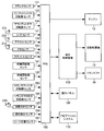
- 1 is a schematic block configuration diagram of a vehicle including a control device according to a first embodiment of the present invention. It is a schematic block block diagram of the vehicle control in the 1st Embodiment of this invention.
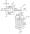
- 1 is a schematic block configuration diagram illustrating a configuration of an automatic transmission according to a first embodiment of the present invention. It is an operation
- the vehicle 10 transmits an engine 12 as a power source and a torque that is generated in the engine 12 and forms a gear stage according to the traveling state of the vehicle 10.
- the front differential mechanism 14 for distributing the torque transmitted from the automatic transmission 13 to the left and right front drive shafts 22L, 22R, and the torque transmitted by the propeller shaft 21 to the left and right rear drive shafts 23L, 23R.
- a rear differential mechanism 15 that transfers the torque transmitted by the automatic transmission 13 to the front wheels 17L and 17R and the rear wheels 18L and 18R, brake devices 24L and 24R that brake the front wheels 17L and 17R, Brake device for braking the rear wheels 18L, 18R 25L, is provided with a 25R, the.
- the vehicle 10 includes an ECU (Electronic Control Unit) 100 as a vehicle electronic control device for controlling the entire vehicle 10, a hydraulic control device 110 that controls the automatic transmission 13 and the transfer 16 by hydraulic pressure, a driver, An operation panel 120 serving as an input / output interface, and a navigation system 170.
- ECU Electronic Control Unit
- the vehicle 10 includes a crank sensor 131, an input shaft rotation speed sensor 133, an output gear rotation speed sensor 134, a shift sensor 141, an accelerator sensor 142, a foot brake sensor (hereinafter referred to as an FB sensor) 143, , Throttle sensor 145, front wheel speed sensor 161, rear wheel speed sensor 162, transfer input speed sensor 163, transfer output speed sensor 164, distribution SW sensor 165, tilt detection sensor 166, seat A position sensor 167 and other various sensors (not shown) are provided. Each sensor provided in the vehicle 10 outputs a detected detection signal to the ECU 100.
- the engine 12 is configured by a known power device that outputs torque by burning a mixture of hydrocarbon fuel such as gasoline or light oil and air in a combustion chamber of a cylinder (not shown).
- the engine 12 performs automatic transmission by reciprocating the piston in the cylinder by intermittently repeating the intake, combustion, and exhaust of the air-fuel mixture in the combustion chamber, and rotating the crankshaft connected to the piston so that power can be transmitted. Torque is transmitted to the machine 13.
- the fuel used for the engine 12 may be an alcohol fuel containing alcohol such as ethanol.
- the automatic transmission 13 includes a plurality of planetary gear devices, and takes gear stages according to a combination of engagement states and release states of clutches and brakes as a plurality of friction engagement elements provided in these planetary gear devices. It is like that.
- the clutch and brake can be switched between an engaged state and a released state by a hydraulic control device 110.
- the automatic transmission 13 decelerates or increases the rotation of the crankshaft input as the power of the engine 12, that is, the torque at a predetermined gear ratio ⁇ , and outputs it to the front differential mechanism 14 and the transfer 16.
- the stepped transmission is configured to form a shift stage according to the running state and perform speed conversion according to each shift stage. Details of the automatic transmission 13 will be described later.
- the automatic transmission 13 may be a continuously variable transmission that continuously changes the gear ratio.
- the front differential mechanism 14 allows a difference in rotational speed between the front wheel 17L and the front wheel 17R when traveling on a curve or the like.
- the front differential mechanism 14 includes a plurality of gears, and distributes the torque input by the automatic transmission 13 to the front drive shafts 22L and 22R for output.
- the front differential mechanism 14 may be configured such that the front drive shafts 22L and 22R have the same rotation and can take a differential lock state that does not allow a difference in rotational speed between the front wheels 17L and the front wheels 17R. Details of the front differential mechanism 14 will also be described later.
- the rear differential mechanism 15 has substantially the same configuration as the front differential mechanism 14, and therefore description thereof is omitted.
- the transfer 16 is also called an auxiliary transmission, and distributes and transmits the torque transmitted by the automatic transmission 13 to the front differential mechanism 14 and the rear differential mechanism 15, that is, the torque is transmitted to the front wheels 17L and 17R. And can be distributed and transmitted to the rear wheels 18L and 18R.
- the transfer 16 is used during normal travel and four-wheel drive. When traveling, it operates as follows. That is, the transfer 16 does not transmit the torque transmitted by the automatic transmission 13 to the rear differential mechanism 15 but only the front differential mechanism 14 during normal travel. The transfer 16 also transmits the torque transmitted by the automatic transmission 13 to the rear differential mechanism 15 and distributes the torque to the front differential mechanism 14 and the rear differential mechanism 15 during four-wheel drive traveling. It is like that. Details of the transfer 16 will also be described later.
- the brake devices 24L and 24R and the brake devices 25L and 25R include a brake master cylinder, a brake actuator, and a brake body (not shown).
- the brake master cylinder generates a hydraulic pressure corresponding to the depression amount of the foot brake pedal 213.
- the hydraulic pressure generated in the brake master cylinder is transmitted to the brake body via the brake actuator.
- the brake body converts the transmitted hydraulic pressure into a mechanical force to brake the front wheels 17L and 17R and the rear wheels 18L and 18R.
- the brake devices 24L and 24R and the brake devices 25L and 25R are controlled by the ECU 100, and the front wheels 17L and 17R and the rear wheels 18L are controlled by the hydraulic control by the hydraulic control device 110 regardless of the depression amount of the foot brake pedal 213. , 18R is braked.
- the brake device 24L brakes the front wheel 17L
- the brake device 24R brakes the front wheel 17R
- the brake device 25L brakes the rear wheel 18L
- the brake device 25R brakes the rear wheel 18R.
- the ECU 100 includes a CPU (Central Processing Unit) as a central processing unit, a ROM (Read Only Memory) for storing fixed data, a RAM (Random Access Memory) for temporarily storing data, and a rewritable nonvolatile memory.
- a CPU Central Processing Unit
- ROM Read Only Memory
- RAM Random Access Memory
- EEPROM Electrically Erasable and Programmable Read Only Memory
- an input / output interface circuit composed of the above-mentioned memories are provided to control the vehicle 10.
- the ECU 100 is connected to a crank sensor 131, an accelerator sensor 142, and the like.
- the ECU 100 detects the engine speed Ne, the accelerator opening Acc, and the like based on detection signals output from these sensors.
- the ECU 100 has an internal clock and can measure the time. Further, the ECU 100 controls the oil pressure control device 110 to control the oil pressure of each part of the automatic transmission 13 and the transfer 16. Note that the characteristic functions of the ECU 100 will be described later.
- the ROM of the ECU 100 stores an operation table for realizing each gear stage described later and a program for executing vehicle control. Further, the ROM of the ECU 100 also stores a throttle opening degree control map, a shift diagram, a lockup control map, specification values of the vehicle 10 and the like which are not described in detail.
- accelerator depression determination value Acc_tv the brake depression determination value Bf_tv, and the deceleration brake determination value BfDc_tv are stored in the ROM of the ECU 100.
- the accelerator depression determination value Acc_tv is a determination value for determining whether to enter the accelerator on state or the accelerator off state according to the depression amount of the accelerator pedal 212.
- the brake depression determination value Bf_tv is a determination value for determining whether to set the brake on state or the brake off state according to the depression amount of the foot brake pedal 213.
- the deceleration brake determination value BfDc_tv is a determination value for determining whether or not the vehicle 10 is decelerating according to the depression amount of the foot brake pedal 213.
- the deceleration brake determination value BfDc_tv may be calculated according to the traveling state of the vehicle 10.
- an idle determination value and an accelerator lower limit value are also stored in the ROM of the ECU 100.
- the idle determination value is a determination value for determining whether or not the vehicle 10 is in an idle state based on the accelerator opening.
- the accelerator opening used by ECU 100 for the determination is the actual accelerator opening Acc or the control accelerator opening.
- the control accelerator opening is an accelerator opening converted from the actual accelerator opening Acc when a later-described control permission condition is satisfied. Then, the ECU 100 determines that the vehicle 10 is in an idle state when the access opening is equal to or less than the idle determination value, turns on the idle SW, and when the access opening is larger than the idle determination value, It is determined that the vehicle 10 is not in an idle state, and the idle SW is turned off.
- the accelerator lower limit value is a lower limit value when the accelerator opening is converted into the output decrease accelerator opening Acn when the control permission condition is satisfied. Note that the accelerator lower limit value is larger than the idle determination value. Therefore, in the present embodiment, ECU 100 does not make the accelerator opening smaller than the accelerator lower limit value even if the control permission condition is satisfied.
- the vehicle 10 is not in an idle state by the execution of the reduction control that reduces the torque of the vehicle.
- the output reduction accelerator opening Acn may be a predetermined value, but is preferably calculated according to the traveling state of the vehicle 10.
- the hydraulic control device 110 includes linear solenoid valves SLT and SLU as electromagnetic valves controlled by the ECU 100, on / off solenoid valves SL, and linear solenoid valves SL1 to SL5.
- the hydraulic control device 110 is controlled by the ECU 100 to switch the hydraulic circuit and control the hydraulic pressure by the solenoid valves, and operate each part of the automatic transmission 13. Accordingly, the hydraulic control device 110 causes the automatic transmission 13 to configure a desired gear position by switching each solenoid valve.
- the operation panel 120 is connected to the ECU 100 and receives an input operation from the driver, assists the driver, displays the running state of the vehicle, and the like. For example, when the driver inputs a travel mode using a switch or the like provided on the operation panel 120, a signal indicating the input of the travel mode is output to the input / output interface of the ECU 100.
- the navigation system 170 includes a map information storage unit that stores map information including terrain information, a current position acquisition unit that acquires the current position of the vehicle 10 using GPS (Global Positioning System), and a display unit that displays information to the driver.
- the terrain information of the current position of the vehicle 10 is obtained.
- the navigation system 170 provides the driver with a current position, a travel route guidance to the destination, and the like, as in a known car navigation system.
- the crank sensor 131 is controlled by the ECU 100 to detect the rotational speed of the crankshaft 24 and to output a detection signal corresponding to the detected rotational speed to the ECU 100. Further, the ECU 100 acquires the rotation speed of the crankshaft 24 represented by the detection signal output from the crank sensor 131 as the engine rotation speed Ne.
- the input shaft rotational speed sensor 133 is controlled by the ECU 100 to detect the rotational speed of the input shaft 71, which will be described later, and output a detection signal corresponding to the detected rotational speed to the ECU 100.
- the input shaft 71 is directly connected to a turbine shaft 62 of the torque converter 60 described later, and is the same as the rotational speed of the turbine shaft 62. Therefore, hereinafter, the input shaft detected by the input shaft rotational speed sensor 133 is used.
- the rotational speed Nm is set as the turbine rotational speed Nt.
- the output gear rotation speed sensor 134 is controlled by the ECU 100 to detect the rotation speed of an output gear 72 described later and to output a detection signal corresponding to the detected rotation speed to the ECU 100. .
- ECU 100 calculates gear ratio ⁇ based on speed change mechanism input speed Nm input from input shaft speed sensor 133 and speed change mechanism output speed Nc input from output gear speed sensor 134. You can also do that. Note that the speed ratio ⁇ is obtained by dividing the actual rotational speed Nm of the input shaft 71 by the actual rotational speed Nc of the output gear 72.
- the shift sensor 141 is controlled by the ECU 100 to detect which of the plurality of switching positions the shift lever 211 is in, and outputs a detection signal indicating the switching position of the shift lever 211 to the ECU 100. It has become.
- the shift lever 211 has a D position corresponding to a drive range (hereinafter simply referred to as a D range), an N position corresponding to a neutral range, an R position corresponding to a reverse range, from the rear to the front of the vehicle 10. P position corresponding to the parking range is taken.
- a D range a drive range
- N position corresponding to a neutral range
- R position corresponding to a reverse range
- the speed stage of the speed change mechanism 70 described later forms one of the first speed to the sixth speed.
- the ECU 100 The shift speed is selected from the shift speeds based on the vehicle speed V and the throttle opening ⁇ th.
- the accelerator sensor 142 is controlled by the ECU 100 to detect an amount of depression (hereinafter referred to as a stroke) by which the accelerator pedal 212 is depressed, and outputs a detection signal corresponding to the detected stroke to the ECU 100. Yes.
- the ECU 100 calculates the accelerator opening Acc from the stroke of the accelerator pedal 212 represented by the detection signal output from the accelerator sensor 142.
- the accelerator sensor 142 detects the depression of the accelerator pedal 212 and the depression amount. That is, the accelerator sensor 142 constitutes accelerator opening detection means.
- the FB sensor 143 is controlled by the ECU 100 to detect an amount of depression (hereinafter referred to as a stroke) by which the foot brake pedal 213 is depressed, and outputs a detection signal corresponding to the detected stroke to the ECU 100. ing. Further, the ECU 100 calculates the foot brake pedal force Bf from the stroke of the foot brake pedal 213 represented by the detection signal output from the FB sensor 143.
- the FB sensor 143 detects the depression of the foot brake pedal 213. That is, the FB sensor 143 constitutes a brake detection unit.
- the FB sensor 143 detects the amount of depression of the foot brake pedal 213. That is, the FB sensor 143 constitutes a brake pedal force detection means.
- the FB sensor 143 provides a predetermined threshold, that is, a brake depression determination value Bf_tv, for the stroke of the foot brake pedal 213, not the foot brake depression force Bf that represents the stroke of the foot brake pedal 213, and the foot brake that has been depressed
- a foot brake on / off signal may be output depending on whether or not the stroke of the pedal 213 exceeds this threshold value.
- the FB sensor 143 may detect the hydraulic pressure applied to the brake main body provided in the front wheels 17L and 17R, and output a detection signal indicating the hydraulic pressure applied to the brake main body to the ECU 100. Also in this case, the FB sensor 143 provides a predetermined threshold value for the hydraulic pressure of the brake cylinder, and outputs a foot brake on / off signal depending on whether or not the hydraulic pressure of the brake cylinder exceeds this threshold value. Good.
- the throttle sensor 145 is controlled by the ECU 100 to detect the opening degree of the throttle valve of the engine 12 driven by a throttle actuator (not shown), and to output a detection signal corresponding to the detected opening degree to the ECU 100. It has become.
- the ECU 100 is configured to acquire the throttle valve opening represented by the detection signal output from the throttle sensor 145 as the throttle opening ⁇ th.
- the ECU 100 obtains the throttle opening ⁇ th from the accelerator opening Acc based on the throttle opening control map, the throttle obtained from the throttle opening control map without using the detection signal output from the throttle sensor 145.
- the opening degree ⁇ th can be used as a detection value.
- the ECU 100 obtains the throttle opening ⁇ th from the changed output decreasing accelerator opening Acn.
- the front wheel rotational speed sensor 161 is controlled by the ECU 100 to detect the rotational speed of the front drive shaft 22L or 22R and to output a detection signal corresponding to the detected rotational speed to the ECU 100. Further, the ECU 100 acquires the rotational speed of the front drive shaft 22L or 22R represented by the detection signal output from the front wheel rotational speed sensor 161 as the drive shaft rotational speed Nd.
- the ECU 100 calculates the vehicle speed V based on the drive shaft rotational speed Nd acquired from the front wheel rotational speed sensor 161.
- the vehicle speed V indicates a vehicle speed when traveling on a normal traveling road, and will be described below in a situation where the front wheels 17L or 17R slip, for example, when traveling on a rough road.
- a vehicle speed Vr is used.
- the front wheel rotation speed sensor 161 detects the speed of the vehicle 10. That is, the front wheel speed sensor 161 constitutes a vehicle speed detecting means.
- the rear wheel rotational speed sensor 162 is controlled by the ECU 100 to detect the rotational speed of the rear drive shaft 23L or 23R and output a detection signal corresponding to the detected rotational speed to the ECU 100. Further, the ECU 100 is configured to acquire the rotational speed of the rear drive shaft 23L or 23R represented by the detection signal output from the rear wheel rotational speed sensor 162 as the rear wheel rotational speed Nr.
- ECU 100 calculates vehicle body speed Vr based on rear wheel rotational speed Nr acquired from rear wheel rotational speed sensor 162 when driving by only front wheels 17L and 17R, that is, front wheel driving is selected. It is like that.
- the rear wheels 18L and 18R are rolling wheels that are not driven by the engine 12
- the vehicle speed Vr that is the actual vehicle speed of the vehicle 10 is obtained by detecting the rotational speed of the rear wheels 18L and 18R. be able to.
- the rear wheel rotational speed sensor 162 detects the speed of the vehicle 10 from the rotational speed of the rear wheels 18L and 18R, that is, the rotational speed of the rolling wheels in the two-wheel drive. Therefore, the rear wheel speed sensor 162 constitutes a vehicle body speed detecting means.
- the transfer input rotational speed sensor 163 is controlled by the ECU 100 to detect the rotational speed TRin of the input shaft of the transfer 16 and output a detection signal corresponding to the detected rotational speed to the ECU 100. Specifically, the ECU 100 detects the rotational speed of the input shaft 54 of the transfer clutch 53 described later.
- the transfer output rotational speed sensor 164 is controlled by the ECU 100 to detect the rotational speed TRout of the output shaft of the transfer 16 and output a detection signal corresponding to the detected rotational speed to the ECU 100. Specifically, the ECU 100 detects the rotation speed of the propeller shaft 21.
- the distribution SW sensor 165 is controlled by the ECU 100 to detect whether the power changeover switch 215 is in the two-wheel drive selection position or the four-wheel drive selection position, and represents the changeover position of the power changeover switch 215. A detection signal is output to the ECU 100. Further, the power changeover switch 215 selects a distribution ratio between the driving force of the front wheels 17L and 17R and the driving force of the rear wheels 18L and 18R, instead of the two-wheel drive selection and the four-wheel drive selection. It may be possible.
- the tilt detection sensor 166 is controlled by the ECU 100 to detect the tilt angle of the vehicle 10 and output a detection signal corresponding to the detected tilt angle to the ECU 100.
- the inclination detection sensor 166 includes a weight supported so as to be swingable in the front-rear, left-right direction of the vehicle 10, and a signal representing a displacement that the weight has moved according to the front-rear, left-right inclination of the vehicle 10. To output.
- the seat position sensor 167 is controlled by the ECU 100 to detect the position of the driver's seat where the driver is seated, and to output a detection signal corresponding to the detected seat position to the ECU 100.
- the seat position takes a smaller value toward the front.
- the front means the one closer to the accelerator pedal 212, the foot brake pedal 213, the steering wheel, and the like.
- the ECU 100 determines whether or not the vehicle is traveling on a rough road based on the position of the driver's seat detected by the seat position sensor 167. Specifically, the ECU 100 is traveling on a rough road when the position of the driver's seat detected by the seat position sensor 167 is equal to or less than a preset rough road determination seat position, that is, when it is ahead. If it is determined that there is a driver's seat and the detected position of the driver's seat exceeds the rough road determination seat position, it is determined that the vehicle is not traveling on a rough road.
- the automatic transmission 13 includes a torque converter 60 that transmits torque output from the engine 12, a rotation speed of an input shaft 71 that is an input shaft, and a rotation speed of an output gear 72 that is an output gear. And a speed change mechanism 70 that performs the speed change.
- a reduction gear mechanism is provided between the speed change mechanism 70 and the front differential mechanism 14 so as to input torque from the speed change mechanism 70 and increase the driving force while decreasing the rotational speed to output to the front differential mechanism 14.
- torque is directly transmitted from the speed change mechanism 70 to the front differential mechanism 14 without providing a reduction gear mechanism in order to simplify the description.
- the torque converter 60 is disposed between the engine 12 and the transmission mechanism 70, and changes the direction of the oil flow, the pump impeller 63 that inputs torque from the engine 12, the turbine runner 64 that outputs torque to the transmission mechanism 70, and the oil flow.
- a stator 66 and a lock-up clutch 67 that directly connects the pump impeller 63 and the turbine runner 64 are provided to transmit torque via oil.
- the pump impeller 63 is connected to the crankshaft 24 of the engine 12. Further, the pump impeller 63 is rotated integrally with the crankshaft 24 by the torque of the engine 12.
- the turbine runner 64 is connected to the turbine shaft 62, and the turbine shaft 62 is connected to the speed change mechanism 70.
- the turbine shaft 62 is directly connected to an input shaft 71 that is an input shaft of the speed change mechanism 70.
- the turbine runner 64 is rotated by the flow of oil pushed out by the rotation of the pump impeller 63, and outputs the rotation of the crankshaft 24 of the engine 12 to the speed change mechanism 70 via the turbine shaft 62. .
- the stator 66 is rotatably supported by the housing 31 of the automatic transmission 13 serving as a non-rotating member via a one-way clutch 65.
- the stator 66 flows out of the turbine runner 64 and again changes the direction of the oil flowing into the pump impeller 63 to change the force to further rotate the pump impeller 63.
- the stator 66 is prevented from rotating by the one-way clutch 65, and changes the direction in which this oil flows.
- stator 66 rotates idly and prevents reverse torque from acting on the turbine runner 64.
- the lock-up clutch 67 directly connects the pump impeller 63 and the turbine runner 64, and mechanically directly transmits the rotation of the crankshaft 24 of the engine 12 to the turbine shaft 62.
- the torque converter 60 transmits rotation between the pump impeller 63 and the turbine runner 64 via oil. Therefore, the rotation of the pump impeller 63 cannot be transmitted 100% to the turbine runner 64. Therefore, when the rotational speed of the crankshaft 24 and the turbine shaft 62 approaches, the lockup clutch 67 is operated to mechanically directly connect the pump impeller 63 and the turbine runner 64. More specifically, the crankshaft 24 And the turbine shaft 62 are mechanically connected directly to increase the transmission efficiency of the rotation from the engine 12 to the speed change mechanism 70 and improve the fuel efficiency.
- the lock-up clutch 67 can realize a flex lock-up that slides at a predetermined slip rate.
- the state of the lock-up clutch 67 is determined based on the travel state of the vehicle 10 based on the lock-up control map stored in the ROM of the ECU 100, specifically, the CPU of the ECU 100 according to the vehicle speed V and the accelerator opening Acc. To be selected.
- the state of the lock-up clutch 67 includes a converter state in which the lock-up clutch 67 is released, a lock-up state in which the lock-up clutch 67 is fastened, and a flex lock-up state in which the lock-up clutch 67 is slid. , One of the states.
- the pump impeller 63 is provided with a mechanical oil pump 68 that generates hydraulic pressure for shifting the speed change mechanism 70 and hydraulic pressure for supplying oil for operation, lubrication and cooling to each part. ing.
- the transmission mechanism 70 includes an input shaft 71, an output gear 72, a first planetary gear device 73, a second planetary gear device 74, a C1 clutch 75, a C2 clutch 76, a B1 brake 77, a B2 brake 78, and a B3.
- a brake 79 and an F one-way clutch 80 are provided.
- the input shaft 71 is directly connected to the turbine shaft 62 of the torque converter 60. Therefore, the input shaft 71 directly inputs the output rotation of the torque converter 60.
- the output gear 72 is connected to the carrier of the second planetary gear unit 74 and engages with a differential ring gear 42 described later of the front differential mechanism 14 to function as a counter drive gear. Therefore, the output gear 72 transmits the output rotation of the speed change mechanism 70 to the front differential mechanism 14.
- the first planetary gear unit 73 is composed of a single pinion type planetary gear mechanism.
- the first planetary gear device 73 includes a sun gear S1, a ring gear R1, a pinion gear P1, and a carrier CA1.
- the sun gear S1 is connected to the input shaft 71. Therefore, the sun gear S ⁇ b> 1 is connected to the turbine shaft 62 of the torque converter 60 via the input shaft 71.
- the ring gear R1 is selectively fixed to the housing 31 of the automatic transmission 13 via the B3 brake 79.
- the pinion gear P1 is rotatably supported by the carrier CA1.
- the pinion gear P1 is engaged with the sun gear S1 and the ring gear R1.
- the carrier CA1 is selectively fixed to the housing 31 via the B1 brake 77.
- the second planetary gear unit 74 is constituted by a Ravigneaux type planetary gear mechanism.
- the second planetary gear unit 74 includes a sun gear S2, ring gears R2 and R3, a short pinion gear P2, a long pinion gear P3, a sun gear S3, a carrier CA2, and a carrier CA3.
- the sun gear S2 is connected to the carrier CA1 of the first planetary gear device 73.
- the ring gears R2 and R3 are selectively connected to the input shaft 71 via the C2 clutch 76.
- the ring gears R2 and R3 are selectively fixed to the housing 31 via a B2 brake 78. Also, the ring gears R2 and R3 are prevented from rotating in the direction opposite to the rotation direction of the input shaft 71 (hereinafter referred to as the reverse direction) by the F one-way clutch 80 provided in parallel with the B2 brake 78. Yes.
- the short pinion gear P2 is rotatably supported by the carrier CA2.
- Short pinion gear P2 is engaged with sun gear S2 and long pinion gear P3.
- the long pinion gear P3 is rotatably supported by the carrier CA3.
- the long pinion gear P3 is engaged with the short pinion gear P2, the sun gear S3, and the ring gears R2 and R3.
- the sun gear S3 is selectively connected to the input shaft 71 via the C1 clutch 75.
- the carrier CA2 is connected to the output gear 72.
- the carrier CA3 is connected to the carrier CA2 and the output gear 72.
- the B1 brake 77, the B2 brake 78, and the B3 brake 79 are fixed to the housing 31 of the automatic transmission 13.
- the C1 clutch 75, the C2 clutch 76, the F one-way clutch 80, the B1 brake 77, the B2 brake 78, and the B3 brake 79 (hereinafter simply referred to as the clutch C and the brake B unless otherwise specified) are multi-plate clutches and brakes.
- the hydraulic friction engagement device is controlled to be engaged by a hydraulic actuator.
- the clutch C and the brake B correspond to a hydraulic circuit that is switched according to excitation or non-excitation of the linear solenoid valves SL1 to SL5, SLU and SLT, and the on / off solenoid valve SL of the hydraulic control device 110, or an operating state of a manual valve (not shown)
- the state can be switched between the engaged state and the released state.
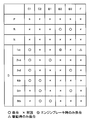
- the operation table for realizing each shift speed is a state in which each friction engagement element of the speed change mechanism 70, that is, the engagement and release states of the clutch C and the brake B, in order to realize each shift speed.
- ⁇ represents engagement.
- X represents release.
- ⁇ represents engagement only during engine braking.
- ⁇ represents engagement only during driving.
- each friction engagement element is operated by excitation, de-excitation, or current control of linear solenoid valves SL1 to SL5 provided in the hydraulic control device 110 (see FIG. 1) and a transmission solenoid (not shown).
- a forward shift stage of 1st to 6th speed and a reverse shift stage are formed.
- the ECU 100 when realizing the first speed, engages the F one-way clutch 80 in addition to the engagement of the C1 clutch 75 during driving. In addition, when realizing the first speed, the ECU 100 engages the B2 brake 78 in addition to the engagement of the C1 clutch 75 when applying the engine brake.
- the ECU 100 engages the B2 brake 78 and the B3 brake 79 when realizing the reverse gear. Further, the ECU 100 releases all of the C1 clutch 75, the C2 clutch 76, the B1 brake 77, the B2 brake 78, the B3 brake 79, and the F one-way clutch 80 when realizing the neutral range and the parking range. As described above, the transmission mechanism 70 is in a neutral state in which torque transmission is not performed between the input and output of the transmission mechanism 70 by releasing all the friction engagement elements.
- the linear solenoid valve SLT controls the hydraulic pressure of the line pressure PL that is the original pressure of the oil supplied to each part.
- the linear solenoid valve SLT includes a throttle opening ⁇ th, an intake air amount Qar of the engine 12, a cooling water temperature Tw of the engine 12, an engine speed Ne, an input shaft speed Nm, that is, a turbine speed Nt, automatic Based on the oil temperature Tf, shift position Psh, shift range, etc. of the transmission 13 and the hydraulic control device 110, the ECU 100 controls the line pressure PL.
- the linear solenoid valve SLU controls the lockup mechanism.
- the linear solenoid valve SLU includes an engine speed Ne that is an input speed of the torque converter 60, a turbine speed Nt that is an output speed of the torque converter 60, a throttle opening ⁇ th, a vehicle speed V, an input torque, and the like. Is controlled by the ECU 100 to adjust the pressure of a lockup relay valve and a lockup control valve (not shown) to control the lockup clutch 67.
- the on / off solenoid valve SL switches the hydraulic pressure of the lockup relay valve.
- the linear solenoid valves SL1 to SL5 are designed to perform shift control.
- Linear solenoid valves SL1 and SL2 control the hydraulic pressures of the C1 clutch 75 and the C2 clutch 76.
- the linear solenoid valves SL3, SL4, and SL5 control the hydraulic pressures of the B1 brake 77, the B2 brake 78, and the B3 brake 79.
- the front differential mechanism 14 includes a hollow differential case 41, a differential ring gear 42 provided on the outer periphery of the differential case 41, a pinion shaft 43 provided inside the differential case 41, and differential pinion gears 44a and 44b. And side gears 45L and 45R.
- the differential pinion gears 44a and 44b and the side gears 45L and 45R are bevel gears.
- the differential case 41 is rotatably held around the front drive shafts 22L and 22R.
- the differential ring gear 42 is provided on the outer periphery of the differential case 41 and is engaged with the output gear 72 of the automatic transmission 13.
- the pinion shaft 43 is fixed so as to rotate integrally with the differential case 41 in parallel with the differential ring gear 42.
- the differential pinion gears 44 a and 44 b are provided to be rotatable around the pinion shaft 43.
- the side gear 45L is provided so as to rotate integrally with the front drive shaft 22L and is engaged with the differential pinion gear 44a and the differential pinion gear 44b.
- the side gear 45R is provided so as to rotate integrally with the front drive shaft 22R, and is engaged with the differential pinion gear 44a and the differential pinion gear 44b.
- the front differential mechanism 14 when the differential pinion gears 44a and 44b do not rotate, the side gear 45L and the side gear 45R rotate equally.
- the front differential mechanism 14 when the differential pinion gears 44a and 44b are rotated, the side gear 45L and the side gear 45R are relatively reversely rotated. Therefore, the front differential mechanism 14 allows a difference in rotational speed between the side gear 45L that rotates integrally with the front drive shaft 22L and the side gear 45R that rotates together with the front drive shaft 22R, and changes a curve or the like. When traveling, the difference in rotational speed between the front wheel 17L and the front wheel 17R can be absorbed.
- the rear differential mechanism 15 has the same configuration as the front differential mechanism 14, and therefore the description thereof is omitted.
- the differential ring gear 42 is engaged with the pinion gear of the propeller shaft 21 instead of the output gear 72 of the automatic transmission 13.
- the left and right side gears of the rear differential mechanism 15 are provided to rotate integrally with the rear drive shafts 23L and 23R instead of the front drive shafts 22L and 22R.
- the transfer 16 includes a hypoid gear 51, a hypoid pinion 52, and a transfer clutch 53.
- the hypoid gear 51 rotates integrally with the differential case 41 of the front differential mechanism 14 and inputs torque from the automatic transmission 13 to the transfer 16 via the front differential mechanism 14.
- the hypoid pinion 52 is, for example, a bevel gear together with the hypoid gear 51, and converts the rotational direction of torque input from the hypoid gear 51 by 90 °.
- the transfer clutch 53 includes an input shaft 54, a multi-plate clutch disk 55, a multi-plate clutch plate 56, and a piston 57, and a hydraulic servo chamber 58 is formed therein.
- the transfer clutch 53 connects the hypoid pinion 52 and the propeller shaft 21 side so as to be able to transmit torque.
- the transfer clutch 53 itself is a known hydraulic servo type wet multi-plate clutch.
- the input shaft 54 is connected to the hypoid pinion 52 so that torque is input from the hypoid pinion 52 and transmitted to the multi-plate clutch disk 55.
- the multi-plate clutch plate 56 transmits torque to the propeller shaft 21.
- the multi-plate clutch disk 55 and the multi-plate clutch plate 56 form a multi-plate clutch.
- the hydraulic pressure in the hydraulic servo chamber 58 is controlled by a hydraulic control device, and when the hydraulic pressure is supplied into the hydraulic servo chamber 58, the piston 57 presses the multi-plate clutch disc 55 and the multi-plate clutch plate 56 with a predetermined pressure. A predetermined torque transmission amount is ensured by this pressing force.
- the transfer 16 distributes the driving force of the engine 12 to the front wheels 17L, 17R and the rear wheels 18L, 18R. That is, the transfer 16 constitutes a power distribution device.
- the ECU 100 determines whether the current travel is traveling on a rough road based on the torque distribution state of the transfer 16. Specifically, the ECU 100 inputs the input shaft rotational speed TRin of the transfer 16 detected by the transfer input rotational speed sensor 163 and the output shaft rotational speed TRout of the transfer 16 detected by the transfer output rotational speed sensor 164. Based on the output speed ratio or the switching state of the power changeover switch 215 of the transfer 16 detected by the distribution SW sensor 165, it is determined whether or not the vehicle is traveling on a rough road.
- the ECU 100 determines whether or not the vehicle is traveling on a rough road based on the selected travel mode. Further, the ECU 100 detects the inclination angle of the vehicle 10 detected by the inclination detection sensor 166, the time change of the inclination angle of the vehicle 10 detected by the inclination detection sensor 166, that is, the driver's seat detected by the swing and the seat position sensor 167. Whether or not the vehicle is traveling on a rough road may be determined based on the difference between the seat position and the position of the driver seat stored in advance in the EEPROM. Further, the ECU 100 determines whether or not the vehicle is traveling on a rough road based on the terrain information of the current position acquired by the navigation system 170.
- ECU100 determines whether the present driving
- the ECU 100 is configured to cut off transmission of torque transmitted from the engine 12 to the front wheels 17L and 17R and the rear wheels 18L and 18R. Further, the ECU 100 is configured to cut off torque transmission by automatically stopping the engine 12 when a predetermined stop condition is satisfied. Therefore, the ECU 100 has an eco-run control function for automatically stopping the engine 12.
- the ECU 100 turns on the idle SW and automatically stops the engine 12, that is, performs an eco-run control function. That is, the ECU 100 constitutes a power shut-off means.
- the ECU 100 determines that the control permission condition is satisfied when the accelerator sensor 142 detects the depression of the accelerator pedal 212 and the FB sensor 143 detects the depression of the foot brake pedal 213.
- the ECU 100 determines that the control permission condition is satisfied. ing. Further, the ECU 100 determines that the control permission condition is satisfied when the deceleration of the vehicle 10 is determined. That is, the ECU 100 constitutes permission condition determination means.
- the ECU 100 determines that the control permission condition is satisfied, the ECU 100 converts the actual accelerator opening Acc detected by the accelerator sensor 142 into the control accelerator opening to reduce the torque output from the engine 12. Control is to be executed. Further, the ECU 100 executes the decrease control when the vehicle speed V detected by the front wheel speed sensor 161 is equal to or higher than a preset vehicle speed. Further, the ECU 100 is configured to execute the reduction control when it is determined that the control permission condition is satisfied for a preset time or more.
- the ECU 100 is configured to end the lowering control when the depression amount of the accelerator pedal 212 detected by the accelerator sensor 142 changes more than a preset depression amount.
- the ECU 100 ends the reduction control of the driving force output from the engine 12. That is, the ECU 100 constitutes output control means.
- the ECU 100 is configured to prohibit the transmission of torque transmitted from the engine to the front wheels 17L and 17R and the rear wheels 18L and 18R when performing the decrease control. Further, the ECU 100 prohibits the automatic stop of the engine 12 when executing the decrease control.
- the ECU 100 is configured to make the control accelerator opening to be converted equal to or greater than the accelerator lower limit value larger than the idle determination value. That is, the ECU 100 constitutes a power shut-off prohibiting unit.
- the ECU 100 determines deceleration based on the state of the vehicle 10. Further, the ECU 100 determines deceleration based on the depression amount of the foot brake pedal 213 detected by the FB sensor 143. In addition, the ECU 100 determines deceleration based on changes in the rotational speeds of the rear wheels 18L and 18R serving as rolling wheels detected by the rear wheel rotational speed sensor 162. That is, the ECU 100 constitutes a deceleration determination unit.
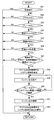
- the flowchart shown in FIG. 6 represents the execution contents of a vehicle control process program executed by the CPU of the ECU 100 using the RAM as a work area.
- This vehicle control processing program is stored in the ROM of the ECU 100.
- the vehicle control process is executed by the CPU of the ECU 100 at predetermined time intervals.
- the ECU 100 determines whether or not the vehicle is traveling on a rough road (step S11).
- the ECU 100 performs the determination method as to whether or not the vehicle is traveling on a rough road by combining one or more of the above-described determination methods of the rough road traveling.
- step S11 When ECU 100 determines that the vehicle is traveling on a rough road (YES in step S11), if the torque of engine 12 is reduced, hesitation or the like occurs and drivability deteriorates. The control process ends.
- ECU 100 determines whether or not the accelerator is on. If the accelerator is not on, the vehicle control process is terminated (Ste S12). Specifically, ECU 100 determines whether or not accelerator opening Acc detected by accelerator sensor 142 is greater than or equal to accelerator depression determination value Acc_tv stored in ROM, and accelerator opening Acc is determined as accelerator depression determination value. If it is greater than or equal to Acc_tv, the accelerator pedal 212 is depressed, that is, it is determined that the accelerator is on, and if the accelerator opening Acc is less than the accelerator depression determination value Acc_tv, the accelerator pedal 212 is not depressed. That is, it is determined that the accelerator is off.
- the ECU 100 determines whether or not the brake is on. If the brake is not on, the vehicle control process is terminated ( Step S13). Specifically, the ECU 100 determines whether or not the brake depression force Bf detected by the FB sensor 143 is greater than or equal to the brake depression determination value Bf_tv stored in the ROM, and the brake depression force Bf is equal to or greater than the brake depression determination value Bf_tv. If it is determined that the foot brake pedal 213 is depressed, that is, the brake is on, and the brake depression force Bf is less than the brake depression determination value Bf_tv, the foot brake pedal 213 is not depressed, It is determined that the brake is off.
- the ECU 100 moves the current brake information stored in the RAM to the previous brake information and stores the determined brake information in the RAM as current brake information during the brake-on determination process (step S13).
- the brake information is information indicating whether the brake is on or the brake is off.
- ECU 100 starts a timer and determines the duration of both the accelerator and brake steps. Monitor.
- Step S13 the ECU 100 determines whether or not the previous brake was off. If the previous brake is not off, the vehicle control process ends. (Step S14). Specifically, the ECU 100 reads the previous brake information stored in the RAM and determines whether or not the brake is off.
- step S12 the accelerator on determination process
- step S13 the brake on determination process
- step S14 the previous brake off determination process
- the ECU 100 determines whether or not the vehicle speed V calculated from the rotational speed detected by the front wheel rotational speed sensor 161 has decreased by a predetermined vehicle speed, and when the vehicle speed V has decreased by a predetermined vehicle speed or more. Determines that the vehicle is decelerating, and determines that the vehicle is not decelerating if the vehicle speed V is not lower than a predetermined vehicle speed.
- the predetermined vehicle speed for determining the deceleration may be a constant value, but is preferably a value corresponding to the vehicle speed V.
- the deceleration determination described above is not a problem because this process is a process during normal driving that is not rough road driving or the like, but in order to be able to cope with rough road driving or the like, the following processing is performed. It is also possible.
- the ECU 100 determines whether or not the brake pedal force Bf detected by the FB sensor 143 is equal to or greater than the deceleration brake determination value BfDc_tv stored in the ROM, and the brake pedal force Bf is equal to or greater than the deceleration brake determination value BfDc_tv. Is determined to be decelerating, and if the brake pedal force Bf is less than the deceleration brake determination value BfDc_tv, it is determined that the vehicle is not decelerating.
- the ECU 100 performs the above-described deceleration determination by determining the rotational speed detected by the rear wheel rotational speed sensor 162 that detects the rotational speed of the rear wheels 18L and 18R serving as rolling wheels.
- the vehicle speed Vr can be obtained from the above, and the deceleration can be determined based on the amount of change in the vehicle speed Vr.
- the transfer 16 is not provided, and the rear wheels 18L, 18R or the front wheels 17L, 17R are always rolling wheels by the two-wheel drive. Therefore, the rear wheel speed sensor 162 or the front wheel speed sensor is always used.
- the vehicle body speed Vr can be obtained by 161, and the deceleration determination can be applied.
- the vehicle 10 may include an acceleration sensor that detects the acceleration of the vehicle 10, and the ECU 100 may perform a deceleration determination based on the acceleration detected by the acceleration sensor.
- ECU 100 determines whether or not both the accelerator and brake are depressed for less than 10 seconds, and both the accelerator and brake are depressed for 10 seconds or more. If so, the vehicle control process is terminated (step S16).
- the vehicle control process is terminated when the accelerator pedal 212 and the foot brake pedal 213 are always depressed. This is because it cannot be clearly determined whether or not the torque of the engine 12 may be reduced.
- step S11 to S16 determines that the control permission condition (steps S11 to S16) continues for a certain period of time and the vehicle speed V is satisfied when both the accelerator and the brake are depressed for less than 10 seconds (determined as YES in step S16). Is 7 [km / h] or more and if the control permission condition is satisfied and the predetermined time has not yet continued, or if the vehicle speed V is less than 7 [km / h]
- the vehicle control process is terminated (step S17).
- the detection value used for the vehicle speed determination is preferably the vehicle body speed Vr as described above.
- ECU 100 determines that the control permission condition continues for a certain period of time and vehicle speed V is 7 [km / h] or higher (determined as YES in step S17), ECU 100 performs torque reduction control of engine 12. Processing is performed (step S18). A specific method for the reduction control process will be described later.
- the ECU 100 determines whether or not the brake is off, or whether or not the state where the accelerator opening hiss width exceeds the predetermined hiss width has continued for a predetermined time, the brake is on, and the accelerator
- the opening hysteresis width is equal to or less than the predetermined hysteresis width or exceeds the predetermined hysteresis width, if the predetermined time has not elapsed, the process returns to the engine torque reduction control process (step S18) (step S19).
- the accelerator opening hiss width is the difference between the actual accelerator opening Acc before the engine torque reduction control process (step S18) and the current actual accelerator opening Acc detected by the accelerator sensor 142. It shows that.
- step S19 When ECU 100 determines that the brake is off or the accelerator opening hysteresis width has exceeded the predetermined hysteresis width for a predetermined time (YES in step S19), the torque of engine 12 is determined.
- the vehicle control process is terminated (step S20). For example, when the accelerator opening is rewritten in the engine torque reduction control process (step S18), the ECU 100 returns the accelerator opening to the actual accelerator opening Acc detected by the accelerator sensor 142, and The torque of 12 is returned to the torque during normal running.
- FIG. 7 shows a graph representing the conversion of the accelerator opening by the engine torque reduction control process, and the reduction control process by the ECU 100 will be described.
- the ECU 100 sets the accelerator opening value to the actual accelerator position. Acc is reduced until the accelerator opening Acn for lowering the output for reducing the torque of the engine 12 is reached. Thereby, a torque is reduced rather than the engine output by actual accelerator opening Acc.
- the ECU 100 sets an accelerator lower limit value that is larger than the idle determination value, and controls so that the output reduction accelerator opening Acn is equal to or greater than the accelerator lower limit value.
- the rate of decrease of the engine torque that is, the rate of conversion from the actual accelerator opening Acc to the output decreasing accelerator opening Acn, that is, the inclination can be set to a rate according to the situation of the vehicle 10. For example, by converting slowly when the actual accelerator opening Acc is small, and converting earlier as the actual accelerator opening is larger, the time required to reach the accelerator opening Acn for lowering the output is made equivalent. Can do.
- the output opening accelerator opening Acn may not be a fixed value, but may be a value calculated according to the state of the vehicle 10 such as the vehicle speed V or the road inclination.
- the vehicle control apparatus includes the accelerator pedal 212 and the foot brake pedal 213 in the vehicle 10 having the function of blocking the transmission of torque transmitted from the engine 12 to the front wheels 17L and 17R.
- the depression of the engine 12 is detected at the same time, while the reduction control for reducing the torque output from the engine 12 is executed, the interruption of the transmission of the torque generated by the execution of the reduction control is prohibited. Even if it makes it stop, it can prevent that the vehicle 10 stops unnecessarily, and can prevent the deterioration of drivability.
- the vehicle control apparatus provides torque output from the engine 12 in the vehicle 10 having an eco-run control function that automatically stops the engine 12 when a predetermined stop condition is satisfied.
- the automatic stop of the engine 12 that occurs due to the execution of the reduction control is prohibited, so unnecessary automatic stop of the engine 12 can be prevented, and deterioration of drivability can be prevented.
- the vehicle control apparatus determines the control permission conditions, that is, the control access opening degree converted when the above step S11 to step S16 and the control start condition, ie, step S17 are established, of the engine 12. Since the accelerator lower limit value is greater than the idle determination value for automatic stop, the engine 12 is not automatically stopped even if the accelerator opening is converted by the establishment of the control permission condition, and the drivability deteriorates. Can be prevented.
- the control permission conditions that is, the control access opening degree converted when the above step S11 to step S16 and the control start condition, ie, step S17 are established
- ECU 100 determines that the control permission condition is satisfied, the ECU 100 prohibits the automatic stop of the engine 12. That is, the ECU 100 constitutes a power shut-off prohibiting unit. Further, unlike the first embodiment, the ECU 100 is configured to set the control accelerator opening to be converted regardless of the accelerator lower limit value.
- FIG. 8 represents the execution content of the program of the vehicle control process performed by CPU of ECU100 by using RAM as a work area.
- This vehicle control processing program is stored in the ROM of the ECU 100.
- the vehicle control process is executed by the CPU of the ECU 100 at predetermined time intervals.
- steps S31 to S37 and steps S40 to S41 are the same as the processes in steps S11 to S17 and steps S19 to S20 in the first embodiment, detailed description will be given. Omitted.
- step S38 System control referring to the idle SW is prohibited (step S38). Specifically, the ECU 100 prohibits the automatic stop of the engine 12, that is, the execution of the eco-run control function even when the idle SW is turned on.
- the ECU 100 performs a torque reduction control process for the engine 12 (step S39). Specifically, the ECU 100 decreases the accelerator opening value until the output opening accelerator opening Acn for reducing the torque of the engine 12 is reduced from the actual accelerator opening Acc.
- the ECU 100 sets the output reduction accelerator opening Acn without being caught by the accelerator lower limit value.
- step S39 the ECU 100 determines that the brake is off or the state where the accelerator opening hysteresis width exceeds the predetermined hysteresis width continues for a predetermined time after the engine torque reduction control process (step S39) (step S40). Is determined as YES), the process of restoring the torque of the engine 12 is performed (step S41), the prohibition of the system control referring to the idle SW is canceled, and the vehicle control process is terminated (step S42).
- the vehicle control apparatus refers to the idle SW when the control permission condition, that is, the above-described steps S31 to S36 and the control start condition, that is, the above-described step S37 is established. Since the system control is prohibited, that is, the eco-run control for automatically stopping the engine 12 is prohibited, the torque output from the engine 12 is reduced when the depression of the accelerator pedal 212 and the foot brake pedal 213 is simultaneously detected. While executing the decrease control, the engine 12 is not automatically stopped, and the drivability can be prevented from deteriorating.
- the control permission condition that is, the above-described steps S31 to S36 and the control start condition, that is, the above-described step S37 is established. Since the system control is prohibited, that is, the eco-run control for automatically stopping the engine 12 is prohibited, the torque output from the engine 12 is reduced when the depression of the accelerator pedal 212 and the foot brake pedal 213 is simultaneously detected. While executing the decrease control, the engine 12 is not automatically stopped, and the drivability can be prevented from deteriorating.
- the ECU 100 determines that the engine is in an idle state when the control accelerator opening is equal to or less than the idle determination value. That is, the ECU 100 constitutes idle determination means. Similarly to the second embodiment, the ECU 100 is configured to set the control accelerator opening to be converted regardless of the accelerator lower limit value.
- the ECU 100 is configured to automatically stop the engine 12 when it is determined that the engine is in an idle state. That is, the ECU 100 constitutes a power shut-off means. Further, during execution of the decrease control, the ECU 100 does not turn on the idle SW even if the control accelerator opening is equal to or less than the idle determination value, and therefore does not determine the idle state. That is, the ECU 100 constitutes a power shut-off prohibiting unit.
- FIG. 9 represents the execution contents of a vehicle control processing program executed by the CPU of the ECU 100 using the RAM as a work area.
- This vehicle control processing program is stored in the ROM of the ECU 100.
- the vehicle control process is executed by the CPU of the ECU 100 at predetermined time intervals.
- steps S51 to S57 and steps S61 to S62 are the same as the processes in steps S11 to S17 and steps S19 to S20 in the first embodiment, a detailed description will be given. Omitted.
- step S58 A torque reduction control process for the engine 12 is performed (step S58). Specifically, the ECU 100 decreases the accelerator opening value until the output opening accelerator opening Acn for reducing the torque of the engine 12 is reduced from the actual accelerator opening Acc.
- the ECU 100 sets the output reduction accelerator opening Acn without being caught by the accelerator lower limit value.
- the ECU 100 determines whether or not the converted accelerator opening, that is, the output decreasing accelerator opening Acn is equal to or less than the idle determination value, that is, whether or not the idle SW is turned on or less ( Step S59).
- step S59 if the converted accelerator opening is equal to or less than the idle determination value (YES in step S59), the ECU 100 turns off the idle SW, that is, turns off the idle SW (step S60). On the other hand, if the converted accelerator opening is larger than the idle determination value (determined as NO in step S59), ECU 100 does nothing and shifts to the next process.
- the ECU 100 determines whether the brake is off or whether the state where the accelerator opening hysteresis width exceeds a predetermined hysteresis width has continued for a predetermined time, When the brake is on and the accelerator opening hysteresis width is equal to or less than the predetermined hysteresis width or exceeds the predetermined hysteresis width, the predetermined time has not elapsed, and the process returns to the engine torque reduction control process (step S58). (Step S61).
- step S61 determines that the brake is off or the accelerator opening hysteresis width exceeds the predetermined hysteresis width for a predetermined time (YES in step S61), the engine 12 Torque return processing is performed, and this vehicle control processing is terminated (step S62).
- the vehicle control apparatus when the control permission condition, that is, when the above steps S51 to S56 are not satisfied, the control accelerator opening is equal to or less than the idle determination value.
- the idling switch is turned on and the engine 12 is automatically stopped by the eco-run control function, the idling switch is not turned on and the idling state is not determined (step S60).
- the engine 12 is not automatically stopped by the execution of the decrease control, and the drivability can be prevented from deteriorating.
- the brake devices 24L, 24R, 25L, and 25R perform braking on the front wheels 17L and 17R and the rear wheels 18L and 18R. That is, the brake devices 24L, 24R, 25L, and 25R constitute braking means.
- the ECU 100 executes holding control for holding the braking of the front wheels 17L, 17R and the rear wheels 18L, 18R in the brake devices 24L, 24R, 25L, 25R, thereby causing the front wheels from the engine 12 to operate. Transmission of torque to 17L, 17R and rear wheels 18L, 18R is cut off.
- the ECU 100 is configured to perform the holding control when the control accelerator opening is equal to or less than the idle determination value. That is, the ECU 100 constitutes a power shut-off means.
- the ECU 100 does not execute the holding control for holding the braking of the front wheels 17L, 17R and the rear wheels 18L, 18R in the brake devices 24L, 24R, 25L, 25R when executing the engine torque reduction control.
- the ECU 100 is configured to set the control accelerator opening to be converted to an accelerator lower limit value that is greater than the idle determination value. That is, the ECU 100 constitutes a power shut-off prohibiting unit.
- a brake hold the holding control in which the ECU 100 holds the braking of the front wheels 17L, 17R and the rear wheels 18L, 18R with respect to the brake devices 24L, 24R, 25L, 25R.
- the vehicle control apparatus performs brake hold when a predetermined brake holding condition is satisfied, instead of the automatic stop of the engine 12 by the eco-run function according to the first embodiment. It is like that.
- the operation of the vehicle control process in the present embodiment is the same as the operation of the vehicle control process in the first embodiment, that is, the same operation as described with reference to the flowchart shown in FIG.
- the ECU 100 sets the accelerator opening value to the actual value.
- the accelerator opening Acc is reduced until the accelerator opening Acn for lowering the output becomes equal to or greater than the accelerator lower limit greater than the idle determination value.
- the vehicle control apparatus executes a brake hold that holds the braking of the front wheels 17L and 17R and the rear wheels 18L and 18R when a predetermined braking holding condition is satisfied.
- the control access opening that is converted when the control permission condition is satisfied is greater than or equal to the accelerator lower limit value that is larger than the idle determination value for executing the brake hold, the accelerator opening is converted when the control permission condition is satisfied.
- the brake hold is not performed, and the drivability can be prevented from deteriorating.
- the ECU 100 When it is determined that the control permission condition is satisfied, the ECU 100 does not execute the holding control for holding the braking of the front wheels 17L, 17R and the rear wheels 18L, 18R in the brake devices 24L, 24R, 25L, 25R. Yes. That is, the ECU 100 constitutes a power shut-off prohibiting unit. Further, unlike the first embodiment, the ECU 100 is configured to set the control accelerator opening to be converted regardless of the accelerator lower limit value.
- the vehicle control apparatus performs brake hold when a predetermined brake holding condition is satisfied, instead of the automatic stop of the engine 12 by the eco-run function according to the first embodiment. It is like that.
- the operation of the vehicle control process in the present embodiment is the same as the operation of the vehicle control process in the second embodiment, that is, the same operation as described with reference to the flowchart shown in FIG.
- the ECU 100 prohibits system control that refers to the idle SW when the control permission condition is satisfied and the control start condition is satisfied.
- the system control referring to the idle SW is a brake hold function. Therefore, the ECU 100 prohibits execution of brake hold even when the idle SW is turned on.
- the vehicle control apparatus executes a brake hold that holds the braking of the front wheels 17L and 17R and the rear wheels 18L and 18R when a predetermined braking holding condition is satisfied.
- execution of the brake hold is prohibited, so that when the depression of the accelerator pedal 212 and the foot brake pedal 213 is detected at the same time, the torque output from the engine 12 is reduced. Even if the lowering control is executed, the brake hold is not performed, and the drivability can be prevented from deteriorating.
- the ECU 100 determines that the engine is in an idle state when the control accelerator opening is equal to or less than the idle determination value. That is, the ECU 100 constitutes idle determination means. Similarly to the second embodiment, the ECU 100 is configured to set the control accelerator opening to be converted regardless of the accelerator lower limit value.
- the ECU 100 is configured to execute a brake hold when it is determined to be in an idle state. That is, the ECU 100 constitutes a power shut-off means. Further, during execution of the decrease control, the ECU 100 does not turn on the idle SW even if the control accelerator opening is equal to or less than the idle determination value, and therefore does not determine the idle state. That is, the ECU 100 constitutes a power shut-off prohibiting unit.
- the vehicle control apparatus in the present embodiment performs a brake hold when the idle SW is turned on instead of the automatic stop of the engine 12 by the eco-run function in the first embodiment. It has become.
- the operation of the vehicle control process in the present embodiment is the same as the operation of the vehicle control process in the third embodiment, that is, the same operation as described with reference to the flowchart shown in FIG.
- the ECU 100 when the control permission condition is satisfied and the control start condition is satisfied, the ECU 100 changes the accelerator opening value from the actual accelerator opening Acc to the output reduction accelerator opening. Convert to degree Acn. At this time, even if the output reduction accelerator opening degree Acn is equal to or less than the idle determination value for turning on the idle SW, the idle SW is not turned on. Therefore, the ECU 100 is not determined to be in the idle state by the engine torque reduction control process, and does not execute the brake hold.
- the vehicle control apparatus executes a brake hold that holds the braking of the front wheels 17L and 17R and the rear wheels 18L and 18R when a predetermined braking holding condition is satisfied.
- the brake hold due to the execution of the reduction control is not executed, and deterioration of drivability can be prevented.
- the present invention is not limited to this, and an electric vehicle that uses a motor as a power source and hydrogen as fuel. It is also possible to use a hydrogen vehicle using an engine as a power source or a hybrid vehicle using both an engine and a motor.
- the power source for reducing the torque is not limited to the engine 12, but the driving force of a motor or the like may be reduced.
- the present invention is not limited to this, and a plurality of ECUs may be used.
- the ECU 100 of the present embodiment may be configured by a plurality of ECUs such as an E-ECU that performs combustion control of the engine 12 and a T-ECU that performs shift control of the automatic transmission 13. .
- each ECU inputs and outputs necessary information mutually.
- the vehicle control apparatus prohibits the interruption of the power transmission generated by the execution of the reduction control for reducing the driving force output from the power source, and the vehicle even if the driving force is reduced.
- This is useful as a vehicle control device or the like that performs the suppression control of the output of the power source.
Landscapes
- Engineering & Computer Science (AREA)
- Mechanical Engineering (AREA)
- Transportation (AREA)
- Chemical & Material Sciences (AREA)
- Combustion & Propulsion (AREA)
- Automation & Control Theory (AREA)
- General Engineering & Computer Science (AREA)
- Human Computer Interaction (AREA)
- Control Of Vehicle Engines Or Engines For Specific Uses (AREA)
- Control Of Driving Devices And Active Controlling Of Vehicle (AREA)
- Output Control And Ontrol Of Special Type Engine (AREA)
Priority Applications (5)
| Application Number | Priority Date | Filing Date | Title |
|---|---|---|---|
| EP09852235.2A EP2514651B1 (de) | 2009-12-17 | 2009-12-17 | Steuervorrichtung für ein fahrzeug |
| PCT/JP2009/006957 WO2011074037A1 (ja) | 2009-12-17 | 2009-12-17 | 車両の制御装置 |
| JP2011545851A JP5019002B2 (ja) | 2009-12-17 | 2009-12-17 | 車両の制御装置 |
| US13/515,091 US9145115B2 (en) | 2009-12-17 | 2009-12-17 | Vehicle control apparatus |
| CN200980162920.0A CN102725188B (zh) | 2009-12-17 | 2009-12-17 | 车辆控制装置 |
Applications Claiming Priority (1)
| Application Number | Priority Date | Filing Date | Title |
|---|---|---|---|
| PCT/JP2009/006957 WO2011074037A1 (ja) | 2009-12-17 | 2009-12-17 | 車両の制御装置 |
Publications (1)
| Publication Number | Publication Date |
|---|---|
| WO2011074037A1 true WO2011074037A1 (ja) | 2011-06-23 |
Family
ID=44166842
Family Applications (1)
| Application Number | Title | Priority Date | Filing Date |
|---|---|---|---|
| PCT/JP2009/006957 WO2011074037A1 (ja) | 2009-12-17 | 2009-12-17 | 車両の制御装置 |
Country Status (5)
| Country | Link |
|---|---|
| US (1) | US9145115B2 (de) |
| EP (1) | EP2514651B1 (de) |
| JP (1) | JP5019002B2 (de) |
| CN (1) | CN102725188B (de) |
| WO (1) | WO2011074037A1 (de) |
Cited By (4)
| Publication number | Priority date | Publication date | Assignee | Title |
|---|---|---|---|---|
| JP2014137039A (ja) * | 2013-01-18 | 2014-07-28 | Honda Motor Co Ltd | 原動機の出力制御装置 |
| CN109661339A (zh) * | 2016-08-24 | 2019-04-19 | 日立汽车系统株式会社 | 车辆控制装置 |
| US11433861B2 (en) * | 2019-08-09 | 2022-09-06 | Toyota Jidosha Kabushiki Kaisha | Drive assistance device |
| EP4282718A1 (de) * | 2022-05-26 | 2023-11-29 | Toyota Jidosha Kabushiki Kaisha | Steuerungsvorrichtung, steuerungssystem, steuerungsverfahren, nichtflüchtiges speichermedium und fahrzeug |
Families Citing this family (18)
| Publication number | Priority date | Publication date | Assignee | Title |
|---|---|---|---|---|
| US9050965B2 (en) | 2009-12-17 | 2015-06-09 | Toyota Jidosha Kabushiki Kaisha | Vehicle control apparatus |
| US9145115B2 (en) | 2009-12-17 | 2015-09-29 | Toyota Jidosha Kabushiki Kaisha | Vehicle control apparatus |
| JP4915489B2 (ja) * | 2009-12-28 | 2012-04-11 | トヨタ自動車株式会社 | 車両の制御装置 |
| CN103347764B (zh) * | 2011-02-10 | 2015-07-29 | 丰田自动车株式会社 | 混合动力车辆及混合动力车辆的控制方法 |
| US9435275B2 (en) * | 2011-07-01 | 2016-09-06 | Toyota Jidosha Kabushiki Kaisha | Vehicle control apparatus |
| US9352737B2 (en) * | 2012-10-08 | 2016-05-31 | Ford Global Technologies, Llc | Method and system for operating a hybrid powertrain |
| JP5673659B2 (ja) * | 2012-12-10 | 2015-02-18 | トヨタ自動車株式会社 | 車両用制御装置 |
| JP2014125948A (ja) * | 2012-12-26 | 2014-07-07 | Isuzu Motors Ltd | 車両 |
| JP6036851B2 (ja) * | 2013-01-11 | 2016-12-07 | 日産自動車株式会社 | ステアリング制御装置、ステアリング制御方法 |
| GB201314795D0 (en) * | 2013-08-19 | 2013-10-02 | Jaguar Land Rover Ltd | Driveline and method of controlling a driveline |
| JP5954358B2 (ja) * | 2014-05-21 | 2016-07-20 | トヨタ自動車株式会社 | 駆動制御装置 |
| JP6311513B2 (ja) * | 2014-07-28 | 2018-04-18 | 株式会社ジェイテクト | 四輪駆動車及び四輪駆動車の制御方法 |
| JP6540086B2 (ja) * | 2015-02-20 | 2019-07-10 | 三菱自動車工業株式会社 | 四輪駆動車の制御装置 |
| CN110446638B (zh) * | 2017-03-24 | 2022-04-05 | 本田技研工业株式会社 | 发动机起动控制装置 |
| JP2019206206A (ja) * | 2018-05-28 | 2019-12-05 | トヨタ自動車株式会社 | 駆動力制御装置 |
| GB2580924B (en) * | 2019-01-30 | 2021-05-26 | Ford Global Tech Llc | A method of inhibiting stopping of an engine |
| US11603112B2 (en) * | 2019-10-17 | 2023-03-14 | Toyota Motor Engineering & Manufacturing North America, Inc. | Adaptable drive mode systems and methods |
| US20230250784A1 (en) * | 2022-02-10 | 2023-08-10 | Ford Global Technologies, Llc | Methods and systems for inhibiting automatic engine shutdown |
Citations (3)
| Publication number | Priority date | Publication date | Assignee | Title |
|---|---|---|---|---|
| JPS6251737A (ja) | 1985-08-31 | 1987-03-06 | ロ−ベルト・ボツシユ・ゲゼルシヤフト・ミツト・ベシユレンクテル・ハフツング | 自己着火式内燃機関の安全緊急走行方法及び装置 |
| JP2003175747A (ja) * | 2001-12-13 | 2003-06-24 | Denso Corp | エンジン自動停止再始動装置 |
| JP2008174048A (ja) * | 2007-01-17 | 2008-07-31 | Toyota Motor Corp | 車両の制御装置、制御方法、その方法を実現するプログラムおよびそのプログラムを記録した記録媒体 |
Family Cites Families (31)
| Publication number | Priority date | Publication date | Assignee | Title |
|---|---|---|---|---|
| JP3333813B2 (ja) | 1996-11-20 | 2002-10-15 | トヨタ自動車株式会社 | 乗員保護装置の起動制御装置 |
| JP2000344046A (ja) | 1999-06-03 | 2000-12-12 | Asuko Kk | 乗員保護装置用制御システム |
| JP3487279B2 (ja) | 2000-10-02 | 2004-01-13 | トヨタ自動車株式会社 | 乗員保護装置の起動制御装置 |
| EP1666712B1 (de) * | 2001-01-26 | 2008-09-03 | Denso Corporation | Kraftwerksteuerapparat |
| JP3588091B2 (ja) | 2002-08-22 | 2004-11-10 | 本田技研工業株式会社 | ハイブリッド車両の油圧制御装置 |
| JP3701660B2 (ja) | 2003-07-04 | 2005-10-05 | 本田技研工業株式会社 | ハイブリッド車両の制御装置 |
| JP3926774B2 (ja) | 2003-07-04 | 2007-06-06 | 本田技研工業株式会社 | ハイブリッド車両の制御装置 |
| JP3665060B2 (ja) | 2003-07-04 | 2005-06-29 | 本田技研工業株式会社 | ハイブリッド車両の制御装置 |
| EP1493604B1 (de) | 2003-07-04 | 2013-09-18 | Honda Motor Co., Ltd. | Steuerung für ein Hybridfahrzeug |
| JP3746775B2 (ja) | 2003-07-04 | 2006-02-15 | 本田技研工業株式会社 | ハイブリッド車両の制御装置 |
| JP4534586B2 (ja) | 2004-05-11 | 2010-09-01 | トヨタ自動車株式会社 | 動力出力装置およびこれを搭載する自動車並びに動力出力装置の制御方法 |
| DE102005023877A1 (de) * | 2004-06-08 | 2005-12-29 | Continental Teves Ag & Co. Ohg | Verfahren zum Steuern eines Kraftfahrzeugs |
| JP2008049775A (ja) | 2006-08-23 | 2008-03-06 | Toyota Motor Corp | 車両およびその制御方法 |
| JP2008168720A (ja) | 2007-01-10 | 2008-07-24 | Toyota Motor Corp | 自動車およびその制御方法 |
| US7771312B2 (en) * | 2007-03-14 | 2010-08-10 | Honda Motor Co., Ltd. | Selectable drivetrain control for a vehicle |
| JP4973320B2 (ja) | 2007-06-01 | 2012-07-11 | トヨタ自動車株式会社 | 車両およびその制御方法 |
| US8224544B2 (en) | 2007-11-07 | 2012-07-17 | GM Global Technology Operations LLC | Method and apparatus to control launch of a vehicle having an electro-mechanical transmission |
| JP4957528B2 (ja) * | 2007-12-03 | 2012-06-20 | 日産自動車株式会社 | 容量制御式発進クラッチ付き変速機搭載車両の高応答発進制御装置 |
| JP2009166670A (ja) | 2008-01-16 | 2009-07-30 | Toyota Motor Corp | ハイブリッド自動車およびその制御方法 |
| JP4644722B2 (ja) * | 2008-03-31 | 2011-03-02 | 日立建機株式会社 | 電気駆動車両 |
| JP2010038051A (ja) | 2008-08-06 | 2010-02-18 | Denso Corp | 車載動力発生装置のトルク制御装置 |
| US20110112740A1 (en) * | 2009-11-11 | 2011-05-12 | Denso Corporation | Control device for internal combustion engine and method for controlling internal combustion engine |
| US9145115B2 (en) | 2009-12-17 | 2015-09-29 | Toyota Jidosha Kabushiki Kaisha | Vehicle control apparatus |
| US9050965B2 (en) * | 2009-12-17 | 2015-06-09 | Toyota Jidosha Kabushiki Kaisha | Vehicle control apparatus |
| US20120259524A1 (en) * | 2009-12-28 | 2012-10-11 | Toyota Jidosha Kabushiki Kaisha | Vehicle control apparatus |
| JP4915489B2 (ja) * | 2009-12-28 | 2012-04-11 | トヨタ自動車株式会社 | 車両の制御装置 |
| WO2011125122A1 (ja) | 2010-04-07 | 2011-10-13 | トヨタ自動車株式会社 | 車両の制御装置 |
| US20130030675A1 (en) | 2010-04-07 | 2013-01-31 | Toyota Jidosha Kabushiki Kaisha | Vehicle control apparatus |
| JP5299562B2 (ja) | 2010-04-07 | 2013-09-25 | トヨタ自動車株式会社 | 車両の制御装置 |
| JP5472028B2 (ja) | 2010-10-19 | 2014-04-16 | 三菱自動車工業株式会社 | モータトルク制御装置 |
| CN103347764B (zh) | 2011-02-10 | 2015-07-29 | 丰田自动车株式会社 | 混合动力车辆及混合动力车辆的控制方法 |
-
2009
- 2009-12-17 US US13/515,091 patent/US9145115B2/en active Active
- 2009-12-17 CN CN200980162920.0A patent/CN102725188B/zh active Active
- 2009-12-17 WO PCT/JP2009/006957 patent/WO2011074037A1/ja active Application Filing
- 2009-12-17 JP JP2011545851A patent/JP5019002B2/ja active Active
- 2009-12-17 EP EP09852235.2A patent/EP2514651B1/de active Active
Patent Citations (3)
| Publication number | Priority date | Publication date | Assignee | Title |
|---|---|---|---|---|
| JPS6251737A (ja) | 1985-08-31 | 1987-03-06 | ロ−ベルト・ボツシユ・ゲゼルシヤフト・ミツト・ベシユレンクテル・ハフツング | 自己着火式内燃機関の安全緊急走行方法及び装置 |
| JP2003175747A (ja) * | 2001-12-13 | 2003-06-24 | Denso Corp | エンジン自動停止再始動装置 |
| JP2008174048A (ja) * | 2007-01-17 | 2008-07-31 | Toyota Motor Corp | 車両の制御装置、制御方法、その方法を実現するプログラムおよびそのプログラムを記録した記録媒体 |
Non-Patent Citations (1)
| Title |
|---|
| See also references of EP2514651A4 |
Cited By (5)
| Publication number | Priority date | Publication date | Assignee | Title |
|---|---|---|---|---|
| JP2014137039A (ja) * | 2013-01-18 | 2014-07-28 | Honda Motor Co Ltd | 原動機の出力制御装置 |
| CN109661339A (zh) * | 2016-08-24 | 2019-04-19 | 日立汽车系统株式会社 | 车辆控制装置 |
| CN109661339B (zh) * | 2016-08-24 | 2022-04-05 | 日立安斯泰莫株式会社 | 车辆控制装置 |
| US11433861B2 (en) * | 2019-08-09 | 2022-09-06 | Toyota Jidosha Kabushiki Kaisha | Drive assistance device |
| EP4282718A1 (de) * | 2022-05-26 | 2023-11-29 | Toyota Jidosha Kabushiki Kaisha | Steuerungsvorrichtung, steuerungssystem, steuerungsverfahren, nichtflüchtiges speichermedium und fahrzeug |
Also Published As
| Publication number | Publication date |
|---|---|
| US9145115B2 (en) | 2015-09-29 |
| US20120290179A1 (en) | 2012-11-15 |
| JPWO2011074037A1 (ja) | 2013-04-25 |
| EP2514651A1 (de) | 2012-10-24 |
| CN102725188A (zh) | 2012-10-10 |
| EP2514651A4 (de) | 2018-04-18 |
| CN102725188B (zh) | 2015-05-13 |
| JP5019002B2 (ja) | 2012-09-05 |
| EP2514651B1 (de) | 2021-12-15 |
Similar Documents
| Publication | Publication Date | Title |
|---|---|---|
| JP5019002B2 (ja) | 車両の制御装置 | |
| JP5062371B2 (ja) | 車両の制御装置 | |
| JP5182449B2 (ja) | 車両の制御装置 | |
| JP5141829B2 (ja) | 車両の制御装置 | |
| JP4915489B2 (ja) | 車両の制御装置 | |
| JP5278599B2 (ja) | 車両の制御装置 | |
| JP5062369B2 (ja) | 車両の制御装置 | |
| WO2011080798A1 (ja) | 車両の制御装置 | |
| JP5299562B2 (ja) | 車両の制御装置 |
Legal Events
| Date | Code | Title | Description |
|---|---|---|---|
| WWE | Wipo information: entry into national phase |
Ref document number: 200980162920.0 Country of ref document: CN |
|
| 121 | Ep: the epo has been informed by wipo that ep was designated in this application |
Ref document number: 09852235 Country of ref document: EP Kind code of ref document: A1 |
|
| DPE1 | Request for preliminary examination filed after expiration of 19th month from priority date (pct application filed from 20040101) | ||
| WWE | Wipo information: entry into national phase |
Ref document number: 2011545851 Country of ref document: JP |
|
| WWE | Wipo information: entry into national phase |
Ref document number: 13515091 Country of ref document: US |
|
| NENP | Non-entry into the national phase |
Ref country code: DE |
|
| WWE | Wipo information: entry into national phase |
Ref document number: 2009852235 Country of ref document: EP |