WO2011070996A1 - ジッパーテープ、及び、ジッパーテープ付き包装袋 - Google Patents
ジッパーテープ、及び、ジッパーテープ付き包装袋 Download PDFInfo
- Publication number
- WO2011070996A1 WO2011070996A1 PCT/JP2010/071785 JP2010071785W WO2011070996A1 WO 2011070996 A1 WO2011070996 A1 WO 2011070996A1 JP 2010071785 W JP2010071785 W JP 2010071785W WO 2011070996 A1 WO2011070996 A1 WO 2011070996A1
- Authority
- WO
- WIPO (PCT)
- Prior art keywords
- zipper tape
- thin
- rib
- bag
- cut
- Prior art date
- Legal status (The legal status is an assumption and is not a legal conclusion. Google has not performed a legal analysis and makes no representation as to the accuracy of the status listed.)
- Ceased
Links
Images


Classifications
-
- B—PERFORMING OPERATIONS; TRANSPORTING
- B65—CONVEYING; PACKING; STORING; HANDLING THIN OR FILAMENTARY MATERIAL
- B65D—CONTAINERS FOR STORAGE OR TRANSPORT OF ARTICLES OR MATERIALS, e.g. BAGS, BARRELS, BOTTLES, BOXES, CANS, CARTONS, CRATES, DRUMS, JARS, TANKS, HOPPERS, FORWARDING CONTAINERS; ACCESSORIES, CLOSURES, OR FITTINGS THEREFOR; PACKAGING ELEMENTS; PACKAGES
- B65D33/00—Details of, or accessories for, sacks or bags
- B65D33/16—End- or aperture-closing arrangements or devices
- B65D33/25—Riveting; Dovetailing; Screwing; using press buttons or slide fasteners
- B65D33/2508—Riveting; Dovetailing; Screwing; using press buttons or slide fasteners using slide fasteners with interlocking members having a substantially uniform section throughout the length of the fastener; Sliders therefor
- B65D33/2516—Riveting; Dovetailing; Screwing; using press buttons or slide fasteners using slide fasteners with interlocking members having a substantially uniform section throughout the length of the fastener; Sliders therefor comprising tamper-indicating means, e.g. located within the fastener
- B65D33/2533—Riveting; Dovetailing; Screwing; using press buttons or slide fasteners using slide fasteners with interlocking members having a substantially uniform section throughout the length of the fastener; Sliders therefor comprising tamper-indicating means, e.g. located within the fastener the slide fastener being located between the product compartment and the tamper indicating means
-
- B—PERFORMING OPERATIONS; TRANSPORTING
- B65—CONVEYING; PACKING; STORING; HANDLING THIN OR FILAMENTARY MATERIAL
- B65D—CONTAINERS FOR STORAGE OR TRANSPORT OF ARTICLES OR MATERIALS, e.g. BAGS, BARRELS, BOTTLES, BOXES, CANS, CARTONS, CRATES, DRUMS, JARS, TANKS, HOPPERS, FORWARDING CONTAINERS; ACCESSORIES, CLOSURES, OR FITTINGS THEREFOR; PACKAGING ELEMENTS; PACKAGES
- B65D33/00—Details of, or accessories for, sacks or bags
- B65D33/16—End- or aperture-closing arrangements or devices
- B65D33/25—Riveting; Dovetailing; Screwing; using press buttons or slide fasteners
- B65D33/2508—Riveting; Dovetailing; Screwing; using press buttons or slide fasteners using slide fasteners with interlocking members having a substantially uniform section throughout the length of the fastener; Sliders therefor
- B65D33/2541—Riveting; Dovetailing; Screwing; using press buttons or slide fasteners using slide fasteners with interlocking members having a substantially uniform section throughout the length of the fastener; Sliders therefor characterised by the slide fastener, e.g. adapted to interlock with a sheet between the interlocking members having sections of particular shape
-
- B—PERFORMING OPERATIONS; TRANSPORTING
- B65—CONVEYING; PACKING; STORING; HANDLING THIN OR FILAMENTARY MATERIAL
- B65D—CONTAINERS FOR STORAGE OR TRANSPORT OF ARTICLES OR MATERIALS, e.g. BAGS, BARRELS, BOTTLES, BOXES, CANS, CARTONS, CRATES, DRUMS, JARS, TANKS, HOPPERS, FORWARDING CONTAINERS; ACCESSORIES, CLOSURES, OR FITTINGS THEREFOR; PACKAGING ELEMENTS; PACKAGES
- B65D77/00—Packages formed by enclosing articles or materials in preformed containers, e.g. boxes, cartons, sacks or bags
- B65D77/22—Details
- B65D77/30—Opening or contents-removing devices added or incorporated during filling or closing of containers
-
- Y—GENERAL TAGGING OF NEW TECHNOLOGICAL DEVELOPMENTS; GENERAL TAGGING OF CROSS-SECTIONAL TECHNOLOGIES SPANNING OVER SEVERAL SECTIONS OF THE IPC; TECHNICAL SUBJECTS COVERED BY FORMER USPC CROSS-REFERENCE ART COLLECTIONS [XRACs] AND DIGESTS
- Y10—TECHNICAL SUBJECTS COVERED BY FORMER USPC
- Y10T—TECHNICAL SUBJECTS COVERED BY FORMER US CLASSIFICATION
- Y10T24/00—Buckles, buttons, clasps, etc.
- Y10T24/25—Zipper or required component thereof
- Y10T24/2532—Zipper or required component thereof having interlocking surface with continuous cross section
- Y10T24/2534—Opposed interlocking surface having dissimilar cross section
Definitions
- the present invention relates to a zipper tape and a packaging bag with a zipper tape.
- a pair of belt-like zipper tapes that engage the male and female with respect to the opening of the bag body are arranged, and the occlusion state can be freely opened and closed.
- a packaging bag with zipper tape (hereinafter sometimes abbreviated as “packaging bag”) is applied.
- Such a packaging bag is sealed by sealing an opening.
- the sealing portion can be removed so as to tear the base film of the bag body from a notch or notch formed in the edge of the packaging bag.
- a packaging bag that anyone can easily open has been developed, and a packaging bag that can easily tear a base film and is excellent in easy opening (see, for example, Patent Documents 1 and 2). ).
- the fitting described in Patent Document 1 includes a resin layer having an easy-cutting function with a predetermined width that extends along the entire length of the tape portion bonded to the bag body.
- a resin different from the tape portion is used for this resin layer.
- the zipper tape described in Patent Document 2 includes a cut portion at one edge in the width direction of the male member and the female member. This cut part has a thin part thinner than the first thick part and the second thick part between the first thick part and the second thick part. With this configuration, the thin-walled portion is torn at the time of opening, and a sufficient gripping portion of the bag body for releasing the zipper tape can be secured.
- the cut region is wide. Therefore, depending on how to apply a force when tearing the resin layer, the cut line may meander and cannot be easily torn. In addition, when the resin layer is torn, it may be torn at two locations on both ends in the width direction of the resin layer. In that case, the resin layer becomes a fibrous or string-like cut residue, and the appearance is deteriorated or cut. There is a possibility that inconveniences such as debris hindering occlusion and a sufficient seal cannot be obtained. Similarly, the thin-walled portion of Patent Document 2 has a predetermined width dimension, so that the cut line may meander or may be torn at a plurality of locations to generate scraps.
- An object of the present invention is to provide a zipper tape that can be easily opened and a packaging bag with a zipper tape.
- the zipper tape of the present invention is a zipper tape in which a male member and a female member that can be engaged with each other are provided on a pair of band-shaped bases, and at least one end of the pair of band-shaped bases A pair of thick parts thicker than the thickness dimension of the band-shaped base part, a thin part provided between these thick parts and thinner than the thickness part of the thick part, and formed so as to protrude from the thin part. A cut portion having a rib having a thickness dimension substantially the same as the thickness of the meat portion is provided.
- the thickness dimension (D) of the rib is the sum of the height dimension protruding from the thin part of the rib and the thickness dimension of the thin part, and the thickness dimension (D) of the rib. It is preferable that ratio ((D) / (D2)) with respect to the thickness dimension (D2) of the said thick part is 0.8 or more and 1.2 or less. (3) The ratio ((D2) / (D1)) of the thickness dimension (D2) of the thick part to the thickness dimension (D1) of the thin part is preferably 3 or more and 12 or less. . (4) Moreover, it is preferable to have the contact bonding layer on one surface of the said strip
- the packaging bag with a zipper tape of the present invention is formed by applying the zipper tape according to any one of the present invention described above to the inner surface of the opening of the bag body having an opening capable of enclosing the inclusion.
- the base portion, the thick portion, and one surface of the rib are disposed in a bonded state.
- the zipper tape of the present invention since the zipper tape has the rib having substantially the same thickness as the thick portion, when the zipper tape is bonded to the bag body, the thick portion and the rib are bonded to the inner surface of the bag body. be able to. Therefore, when tearing and opening the packaging bag with a zipper tape, it is cut at the thin portion having a tensile strength smaller than that of the thick portion and the rib, so that the cut portion becomes one place and no cutting residue is generated. Moreover, since the cut line is positioned by the rib, the cut line does not meander and can be easily and easily torn.
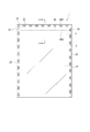
- FIG. 1 The front view which shows the packaging bag with a zipper tape of embodiment which concerns on this invention.
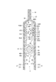
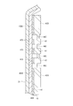
- II-II sectional drawing of FIG. Sectional drawing which expands and shows the cut part of the said packaging bag with a zipper tape.
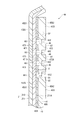
- the front view which expands and shows the notch part vicinity of the said packaging bag with a zipper tape.
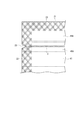
- Sectional drawing which shows the packaging bag with a zipper tape of other embodiment.
- Sectional drawing which shows the packaging bag with a zipper tape which concerns on the comparative example 1.
- FIG. 1 is a front view showing a packaging bag with a zipper tape according to an embodiment of the present invention.
- 2 is a cross-sectional view taken along the line II-II in FIG.
- FIG. 3 is an enlarged cross-sectional view of the cut portion of the packaging bag with a zipper tape.
- a packaging bag 1 with a zipper tape of the present embodiment (hereinafter sometimes abbreviated as “packaging bag 1”) is bonded to a bag body 2 and an inner surface 211 ⁇ / b> A of the bag body 2.
- the bag body 2 is formed by overlapping a base film 21 serving as a packaging material, and includes a side seal portion 22 and a top seal portion 23 on the periphery thereof.
- the top seal portion 23 is formed by sealing the opening 24 into which the filled material of the bag body 2 is charged.
- the side seal portion 22 is formed with a V-shaped notch 25 as a tear start portion at an end portion on the top seal portion 23 side.
- the base film 21 is not limited to a single-layer film, and may be a laminated film having a structure in which a sealant layer 211 is laminated on a base material layer 212. Between the base material layer 212 and the sealant layer 211, depending on required performance. In addition, a laminated film layer having a structure in which a gas barrier layer, a light shielding layer, a strength improving layer and the like are laminated as an intermediate layer may be used.
- a biaxially stretched polypropylene film (OPP film), a biaxially stretched polyethylene terephthalate film (PET film), a biaxially stretched polyester film, a biaxially stretched polyamide film, or the like can be suitably used.
- OPP film biaxially stretched polypropylene film
- PET film biaxially stretched polyethylene terephthalate film
- polyester film a biaxially stretched polyester film
- biaxially stretched polyamide film or the like
- various engineering plastic films can be used as required.
- the sealant layer 211
- the zipper tape 3 is bonded to the inner surface 211 ⁇ / b> A of the opening 24 from one side seal part 22 to the other side seal part 22.
- the zipper tape 3 includes a female band-shaped base 40 having a female member, a cut portion 44 connected to an end of the female side band-shaped base 40 on the opening 24 side, a male side band-shaped base 50 having a male member, A cut portion 54 connected to an end portion of the side band-shaped base portion 50 on the opening 24 side is provided.
- the female side band-shaped base 40 includes a band-shaped base body 41 and a first hook section 42 and a second hook section 43 as female members integrally connected to the band-shaped base body 41.
- the first hook portion 42 and the second hook portion 43 face each other.
- the 1st hook part 42 and the 2nd hook part 43 are engaged with the head 53 of the male side strip
- the female side belt-like base 40 has a bag side surface 40A facing the inner surface 211A, and a seal layer 40B as an adhesive layer for bonding the bag side surface 40A to the inner surface 211A is laminated on the bag side surface 40A. .
- the cut portion 44 includes a first thick portion 45 ⁇ / b> A, a thin portion 46, a rib 47, and a second thick wall in a series from the occlusal portion 6 toward the opening 24.
- the first thick part 45A is disposed on the occlusion part 6 side
- the second thick part 45B is disposed on the opening part 24 side.
- the pair of first and second thick portions 45 ⁇ / b> A and 45 ⁇ / b> B are larger than the thickness of the strip-shaped base body 41 and are formed thick.
- the first and second thick portions 45 ⁇ / b> A and 45 ⁇ / b> B are provided in a longitudinal shape along the longitudinal direction of the strip-shaped base body 41.
- the first thick portion 45A includes a first bag side surface 45A1 that faces the inner surface 211A, and a first inner side surface 45A2 that is the surface opposite to the first bag side surface 45A1 and faces the male side belt-like base portion 50.
- a seal layer 45A3 for adhering the first bag side surface 45A1 to the inner surface 211A is laminated.
- the seal layer 45A3 is formed continuously and integrally with the seal layer 40B.
- the second thick wall portion 45B is also a second bag side surface 45B1 that faces the inner surface 211A, and a second inner side surface that is the surface opposite to the second bag side surface 45B1 and faces the male belt-like base portion 50. 45B2.
- a seal layer 45B3 for adhering the second bag side surface 45B1 to the inner surface 211A is laminated on the second bag side surface 45B1.
- the first and second thick portions 45A and 45B have a thickness dimension (D2).
- the thin portion 46 is disposed in a longitudinal shape between the pair of first and second thick portions 45 ⁇ / b> A and 45 ⁇ / b> B, and both ends in the longitudinal direction are disposed at positions corresponding to the notches 25. Moreover, the thin part 46 has the bag side thin surface 461 which opposes the inner surface 211A, and the inner side thin surface 462 which is a surface on the opposite side to the bag side thin surface 461. The bag-side thin surface 461 is disposed at a position retracted toward the inner side of the bag body 2 in the thickness direction with respect to the first and second bag side surfaces 45A1 and 45B1.
- the bag-side thin surface 461 of the thin-walled portion 46 is provided in a stepped manner with respect to the first and second bag side surfaces 45A1 and 45B1, and has a predetermined interval with respect to the inner surface 211A. It is not glued. Further, the inner thin surface 462 is also disposed at a position retracted toward the inner surface 211A in the thickness direction with respect to the first inner surface 45A2 and the second inner surface 45B2. That is, the inner thin surface 462 of the thin portion 46 is provided in a step shape with respect to the first inner side surface 45A2 and the second inner side surface 45B2.
- the thin-walled portion 46 is connected substantially linearly via a rib 47 to the approximate center in the thickness direction of the first thick-walled portion 45A and the approximate center in the thickness direction of the second thick-walled portion 45B. . Further, the thin portion 46 is formed thinner than the belt-like base body 41 and the first and second thick portions 45A and 45B. And it is preferable that the thickness dimension (D1) of the thin part 46 is 50 micrometers or more, More preferably, it is 60 micrometers or more.
- the thickness dimension (D1) of the thin-walled portion 46 may be bent when the zipper tape 3 is bonded to the inner surface 211A. In this case, the rib 47 is sufficiently formed on the inner surface 211A. There is a possibility that it is not bonded and cannot be cut linearly.
- the thin part 46 is 0.5 mm or more and 5 mm or less in width dimension, and a more preferable range is 1 mm or more and 3 mm or less.
- a more preferable range is 1 mm or more and 3 mm or less.
- the ratio ((D2) / (D1)) between the thickness dimension (D2) of the first and second thick parts 45A and 45B and the thickness dimension (D1) of the thin part 46 is 3 or more and 12 Or less, more preferably 5 or more and 10 or less.
- the thin portion 46 may adhere to the inner surface 211A.
- the ratio ((D2) / (D1)) is larger than 12, the thin-walled portion 46 is likely to be bent, and the above-described problem may occur.
- the rib 47 includes a plurality of bag-side ribs 471 that protrude from the bag-side thin surface 461, a plurality of inner ribs 472 that protrude from the inner thin-wall surface 462, and a thin-wall between the bag-side rib 471 and the inner rib 472. Part 46. Three of these bag-side ribs 471 and three inner ribs 472 are formed. The bag-side rib 471 and the inner rib 472 are provided at substantially the same position in the width direction of the thin portion 46.
- the bag-side rib 471 has a bag-side rib surface 471A facing the inner surface 211A, and a seal layer 473 for bonding the bag-side rib surface 471A to the inner surface 211A is laminated on the bag-side rib surface 471A.
- the inner rib 472 has an inner rib surface 472 ⁇ / b> A that faces the male belt-like base 50.
- the bag-side rib 471 and the inner rib 472 are formed integrally with the thin portion 46, and are formed in a longitudinal shape along the longitudinal direction of the first and second thick portions 45A and 45B.
- the rib 47 has substantially the same thickness dimension (D) as the first and second thick portions 45A and 45B, and the thickness dimension (D) is the height dimension (H11) of the bag-side rib 471. , The sum of the height dimension (H12) of the inner rib 472 and the thickness dimension (D1) of the thin portion 46.
- the ratio ((D) / (D2)) between the thickness dimension (D) of the rib 47 and the thickness dimension (D2) of the first or second thick portion 45A, 45B is 0.8 or more. It is preferably 1.2 or less, more preferably 1.
- the ratio ((D) / (D2)) is larger than 1.2, it is difficult to bond the first and second thick portions 45A and 45B to the inner surface 211A.
- the thickness dimension (D) of the rib 47 is 200 micrometers or more and 700 micrometers or less, More preferably, they are 300 micrometers or more and 600 micrometers or less.
- the thickness dimension (D) of the rib 47 is smaller than 200 ⁇ m, the thin portion 46 may adhere to the inner surface 211A, and may not be easily opened.
- the male side belt-like base 50 has a belt-like base main body 51 and a head 53 as a male member whose section is connected to the belt-like base main body 51 via a connecting portion 52 and has a substantially saddle shape.
- the male side belt-like base 50 includes a belt-like base body 51 and a cut portion 54 similar to the cut portion 44 of the female side belt-like base 40 at the end of the band-like base body 51 on the opening 24 side.
- the cut portion 54 corresponds to the pair of first and second thick portions 45A and 45B, the thin portion 46, the rib 47, the bag side rib 471, and the inner rib 472 of the cut portion 44.
- the bag-side rib 571 and the inner rib 572 of the cut portion 54 have a bag-side rib surface 571A and an inner rib surface 572A corresponding to the bag-side rib surface 471A and the inner rib surface 472A of the cut portion 44.
- the male side belt-like base portion 50 has a bag side surface 50A and first and second bag side surfaces 55A1 and 55B1 corresponding to the bag side surface 40A and the first and second bag side surfaces 45A1 and 45B1.
- the bag side surface 50A, the first and second bag side surfaces 55A1, 55B1, and the bag side rib surface 571A have seal layers 50B, 55A3, 573, 55B3 corresponding to the seal layers 40B, 45A3, 473, 45B3. Are stacked.
- the resin used for the female side strip base 40, the cut portion 44, the male side strip base 50, and the cut portion 54 is a crystalline polyolefin resin.
- a crystalline polyolefin resin examples include low density polyethylene (LD), linear low density polyethylene (LL), and polypropylene (PP), and a mixture of these resins may be used.
- the resin used for the seal layers 40B, 45A3, 473, and 45B3 is preferably a polyolefin resin.
- the polyolefin resin preferably has a lower melting point than the crystalline polyolefin resin used for the female side band-shaped base portion 40 and the cut portion 44.
- the resin used for the seal layers 50B, 55A3, 573, 55B3 is also preferably a polyolefin-based resin, and has a lower melting point than the crystalline polyolefin-based resin used for the male side band-shaped base 50 and the cut portion 54. preferable.
- the zipper tape 3 can be obtained by a co-extrusion method. If it shape
- the packaging bag 1 is manufactured using the base film 21 and the zipper tape 3, using a zipper tape attaching three-way seal bag making machine.
- the zipper tape-attached three-side seal bag making machine positions the zipper tape 3 sent out from the tape sending unit between, for example, the base film 21 sent out from the packaging material sending unit.
- belt-shaped base 50, and the cut part 54 are mutually pressed with a pair of seal bar, and the zipper tape 3 and the base film 21 are adhere
- the base film 21 conveyed is heat-bonded at a predetermined interval with respect to the transport direction of the base film 21 to form the side seal portion 22, and then cut on the side seal portion 22 to be a packaging bag. 1 is formed.
- the point seal process for crushing the zipper tape 3 is implemented.
- FIG. 4 is an enlarged front view showing the vicinity of the notch portion of the packaging bag with a zipper tape.
- the base material film 21 on the opening 24 side of the notch 25 and the base material film 21 on the enclosure side are gripped, and the notch 25 is opened as a tear start part so as to tear back and forth.
- the rib 47 is bonded to the inner surface 211A, stress concentrates on the thin portions 46, 56 having a low tensile strength, and the thin portions 46, 56 where the stress is concentrated are cut. Therefore, since the thin portions 46 and 56 where the stress is concentrated are cut, they are cut only at one place.
- the packaging bag 1 can be opened by releasing the occlusal portion 6 of the zipper tape 3.
- the first hook portion 42 and the second hook portion 43 and the head portion 53 are engaged with each other, and the occlusal portion 6 is brought into an occlusal state.
- the zipper tape 3 Since the rib 47 having a thickness dimension (D) substantially the same as the thickness dimension (D2) of the first and second thick parts 45A and 45B is provided in the cut part 44 of the zipper tape 3, the zipper tape 3 is When bonding to the bag body 2, the first and second thick portions 45A and 45B and the rib 47 can be bonded to the inner surface 211A. Therefore, when the packaging bag 1 is torn and opened, stress concentrates on the thin portion 46 having a small tensile strength, and the thin portion 46 can be cut. Accordingly, there is only one cutting point and no cutting residue is generated. Further, since the cut line C is positioned by the rib 47 when the packaging bag 1 is torn, the straight line cutting property can be obtained without causing the cut line to meander and can be easily torn.
- the inner rib 472 is provided on the opposite side of the bag side rib 471 so as to sandwich the thin portion 46, the thin portion 46 can be reliably cut. That is, it is not cut on the bag-side rib 471 or the inner rib 472.
- the thin portion 46 is disposed at a position retracted from the first and second bag side surfaces 45A1 and 45B1, the thin portion 46 is not bonded to the inner surface 211A, and the thin portions 46 and 56 can be easily cut. Can do.
- the ratio (D) / (D2) between the thickness dimension (D) of the rib 47 and the thickness dimension (D2) of the first and second thick portions 45A and 45B is 0.8 or more. Since it is set to 2 or less, the bag-side rib 471 and the first and second thick portions 45A and 45B can be favorably bonded to the inner surface 211A. Further, since the ratio of the thickness dimension (D) of the rib 47 and the thickness dimension (D2) of the first and second thick portions 45A and 45B is within the above range, the thin portion 46 is formed on the inner surface 211A during bag making. Adhesion can be prevented. In addition, it is possible to prevent pinholes and the like from occurring in the crushed portion in the point sealing process during bag making.
- the ratio ((D2) / (D1)) between the thickness dimension (D2) of the first and second thick portions 45A and 45B and the thickness dimension (D1) of the thin portion 46 is 3 or more and 12 or less. Therefore, it is possible to prevent the thin portion 46 from adhering to the inner surface 211A and the thin portion 46 from being bent.
- the thickness dimension (D1) of the thin portion 46 is 50 ⁇ m or more, the thin portion 46 can be prevented from being bent when the zipper tape 3 is bonded to the inner surface 211A. Therefore, the bag-side rib 471 can be favorably bonded to the inner surface 211A. Therefore, when tearing the packaging bag 1, it is excellent in linear cut property.
- the resin used for the seal layers 40B, 45A3, 45B3, 473 a polyolefin-based resin having a melting point lower than that of the resin used for the female side belt-like base portion 40 and the cut portion 44 is used.
- the zipper tape 3 can be adhered to the surface. Therefore, deterioration of the base material layer 212 which comprises the base material film 21 of the bag body 2 can be suppressed.
- the resin used for the female side belt-like base 40 is a crystalline polyolefin resin, and since this crystalline polyolefin resin is a specific resin such as polypropylene, the rib 47 can be easily molded.
- the zipper tape 3 Since the zipper tape 3 is provided in the bag body 2, it can be set as the packaging bag 1 which is excellent in linear cut property and can be easily torn without generating cutting waste. It should be noted that the cut portion 54 of the male side strip base 50 of the zipper tape 3 has the same effect as the cut portion 44.
- FIG. 5 is a cross-sectional view showing a packaging bag with a zipper tape according to another embodiment.
- the thin-walled portion 46 is configured to connect the first and second thick-walled portions 45A and 45B in a substantially straight line.
- FIG. May be provided.
- one end portion of the thin portion 46C connected to the first thick portion 45A is disposed on the inner surface 211A side, and the other end portion of the thin portion 46C connected to the second thick portion 45B is connected to the bag body 2.
- belt-shaped base 40 showed the structure adhere
- belt-shaped base 40 may be directly adhere
- the thin part 46 is a male side strip
- the thin-walled portion 46 may be provided so as to be disposed on substantially the same plane.
- FIGS. 2 and 3 show a configuration in which three bag-side ribs 471 and three inner ribs 472 are provided in the thin portion 46, but one or more bag-side ribs 471 and inner ribs 472 may be provided.
- three bag-side ribs 471 and three inner ribs 472 are provided, the number of bag-side ribs 471 and the number of inner ribs 472 may be different.
- the cut part 44 was provided in the female side belt-like base 40 and the cut part 54 was provided also in the male side belt-like base 50, the cut was made only on either the female side belt-like base part 40 or the male side belt-like base part 50. The part 44 or the cut part 54 may be provided.
- FIG. 6 is a cross-sectional view showing a zipper tape according to Comparative Example 1
- FIG. 7 is a cross-sectional view showing a zipper tape according to Comparative Example 2.
- Example 1 The zipper tape according to Example 1 was extruded by a commercially available extruder using the following constituent materials. Using the obtained zipper tape and the base film, a packaging bag of Example 1 as shown in FIG. 2 was produced using a zipper tape-attached three-side seal bag making machine. In addition, as a base film, a 12 micrometer polyethylene terephthalate film and linear low density polyethylene (LLDPE) are laminated
- LLDPE linear low density polyethylene
- the zipper tape manufactured under the above conditions has a rib thickness dimension (D) and a thick part thickness dimension (D2) of 300 ⁇ m, and a thin part thickness dimension (D1). ) Is 60 ⁇ m. Moreover, the thin part is not adhere
- Example 2 A zipper tape and a packaging bag were obtained in the same manner as in Example 1 except that the constituent materials of the zipper tape of Example 2 were as follows.
- Comparative Example 1 A zipper tape and a packaging bag according to Comparative Example 1 were obtained in the same manner as in Example 1 except that the following constituent materials were used. As shown in FIG. 6, the zipper tape 9A of Comparative Example 1 was bonded to the inner surface 211A of the bag body 2 on the female side strip base 91A having the female member 91A1 and the male side strip base 92A having the male member 92A1, respectively. A cut portion 93A is provided.
- Female side strip base 91A and male side strip base 92A linear low density polyethylene resin (LLDPE) resin (density 916 kg / m 3 , MFR: 8.5 g / 10 min)
- Cut part 93A crystalline polyolefin resin (density 916 kg / m 3 , MFR: 8.5 g / 10 min) 80% by mass and cyclic polyolefin (MFR: 30 g / 10 min) 20% by mass
- LLDPE linear low density polyethylene resin
- Cut part 93A crystalline polyolefin resin (density 916 kg / m 3 , MFR: 8.5 g / 10 min) 80% by mass and cyclic polyolefin (MFR: 30 g / 10 min) 20% by mass
- the zipper tape 9B of Comparative Example 2 includes a female side belt-like base portion 91B having a female member 91B1 bonded through a seal layer 93B and a male side belt-like base portion 92B having a male member 92B1. And the female side strip
- belt-shaped base part 92B have the thin part 95 which connects a pair of thick part 94A, 94B.
- Comparative Example 3 A zipper tape and a packaging bag of Comparative Example 3 were obtained in the same manner as in Example 1 except that the thickness dimension (D2) of the thin part was 40 ⁇ m.
- Comparative Example 4 A zipper tape and a packaging bag of Comparative Example 4 were obtained in the same manner as in Example 1 except that the thickness dimension (D) of the rib was set to 100 ⁇ m.
- Comparative Example 5 A zipper tape and a packaging bag of Comparative Example 5 were obtained in the same manner as in Example 1 except that the thickness dimension (D) of the rib was set to 800 ⁇ m.
- Comparative Example 4 since the rib was made as thin as 100 ⁇ m, it was found that the thin portion was adhered at the time of bag making. In Comparative Example 5, since the rib was made as thick as 800 ⁇ m, it was found that a pinhole was generated when the side seal portion was formed. That is, it was found that the thickness dimension (D1) of the thin portion of the zipper tape of the present invention is desirably about 60 ⁇ m, and the thickness dimension (D) of the rib is desirably about 300 ⁇ m.
- the present invention can be widely used for, for example, a zipper tape and a packaging bag with a zipper tape for packaging various articles such as foods, medicines, medical products, and miscellaneous goods.
Landscapes
- Engineering & Computer Science (AREA)
- Mechanical Engineering (AREA)
- Bag Frames (AREA)
Priority Applications (4)
| Application Number | Priority Date | Filing Date | Title |
|---|---|---|---|
| CA2781662A CA2781662A1 (en) | 2009-12-11 | 2010-12-06 | Zipper tape and packaging bag with zipper tape |
| EP10835916.7A EP2511186A4 (en) | 2009-12-11 | 2010-12-06 | ZIPPER BELT AND PACKAGING BAG WITH ZIPPED BELT |
| US13/514,615 US20120275730A1 (en) | 2009-12-11 | 2010-12-06 | Zipper tape and packaging bag with zipper tape |
| CN2010800562117A CN102652097A (zh) | 2009-12-11 | 2010-12-06 | 卡扣带及带有卡扣带的包装袋 |
Applications Claiming Priority (2)
| Application Number | Priority Date | Filing Date | Title |
|---|---|---|---|
| JP2009-281228 | 2009-12-11 | ||
| JP2009281228A JP5595026B2 (ja) | 2009-12-11 | 2009-12-11 | ジッパーテープ、及び、ジッパーテープ付き包装袋 |
Publications (1)
| Publication Number | Publication Date |
|---|---|
| WO2011070996A1 true WO2011070996A1 (ja) | 2011-06-16 |
Family
ID=44145540
Family Applications (1)
| Application Number | Title | Priority Date | Filing Date |
|---|---|---|---|
| PCT/JP2010/071785 Ceased WO2011070996A1 (ja) | 2009-12-11 | 2010-12-06 | ジッパーテープ、及び、ジッパーテープ付き包装袋 |
Country Status (8)
| Country | Link |
|---|---|
| US (1) | US20120275730A1 (enExample) |
| EP (1) | EP2511186A4 (enExample) |
| JP (1) | JP5595026B2 (enExample) |
| KR (1) | KR20120102697A (enExample) |
| CN (1) | CN102652097A (enExample) |
| CA (1) | CA2781662A1 (enExample) |
| TW (1) | TW201134725A (enExample) |
| WO (1) | WO2011070996A1 (enExample) |
Cited By (1)
| Publication number | Priority date | Publication date | Assignee | Title |
|---|---|---|---|---|
| WO2021060235A1 (ja) * | 2019-09-27 | 2021-04-01 | 出光ユニテック株式会社 | テープ、ジッパーテープ、テープ付き容器およびその製造方法 |
Families Citing this family (19)
| Publication number | Priority date | Publication date | Assignee | Title |
|---|---|---|---|---|
| US4455489A (en) * | 1981-11-19 | 1984-06-19 | Varian Associates, Inc. | Quadrupole singlet focusing for achromatic parallel-to-parallel devices |
| JP5638278B2 (ja) * | 2009-10-19 | 2014-12-10 | 出光ユニテック株式会社 | 易裂き性ジッパーテープ、及び、易裂き性ジッパーテープ付き包装袋 |
| JP5639091B2 (ja) * | 2010-02-12 | 2014-12-10 | 出光ユニテック株式会社 | ジッパーテープおよびジッパーテープ付包装袋 |
| US8550716B2 (en) * | 2010-06-22 | 2013-10-08 | S.C. Johnson & Son, Inc. | Tactile enhancement mechanism for a closure mechanism |
| JP2013028394A (ja) * | 2011-07-29 | 2013-02-07 | Fuji Tokushu Shigyo Kk | ジッパー付ピロー包装袋及びこのピロー包装袋に用いられるジッパー |
| JP6041494B2 (ja) * | 2012-01-23 | 2016-12-07 | 出光ユニテック株式会社 | カットテープ、ジッパーテープ、及び包装袋 |
| JP6087560B2 (ja) * | 2012-09-28 | 2017-03-01 | 富士特殊紙業株式会社 | ジッパー付ピロー包装袋 |
| JP6139102B2 (ja) * | 2012-11-01 | 2017-05-31 | 富士特殊紙業株式会社 | 直進カット補助テープ付ピロー包装袋及びその製法 |
| JP6139290B2 (ja) * | 2013-06-18 | 2017-05-31 | 富士特殊紙業株式会社 | ジッパー付ピロー包装袋 |
| CN104555037A (zh) * | 2013-10-21 | 2015-04-29 | 大连竹菱包装工业有限公司 | 带撕裂条的一体塑料开闭条及其包装袋 |
| JP2014196145A (ja) * | 2014-06-16 | 2014-10-16 | 出光ユニテック株式会社 | ジッパーテープ、及び、包装袋 |
| JP6113339B1 (ja) | 2016-08-01 | 2017-04-12 | 出光ユニテック株式会社 | テープ及び袋体 |
| JP7285642B2 (ja) * | 2018-12-25 | 2023-06-02 | タキロンシーアイ株式会社 | 嵌合具および嵌合具付き袋体 |
| JP7317574B2 (ja) * | 2019-05-28 | 2023-07-31 | 株式会社生産日本社 | 緩衝袋 |
| KR102877218B1 (ko) * | 2019-09-20 | 2025-10-27 | 이데미쓰 유니테크 가부시키가이샤 | 테이프, 지퍼 테이프, 테이프가 부착된 용기 및 지퍼 테이프가 부착된 용기 |
| JPWO2021246501A1 (enExample) * | 2020-06-05 | 2021-12-09 | ||
| JP2022134111A (ja) * | 2021-03-02 | 2022-09-14 | 出光ユニテック株式会社 | テープ、テープ付き容器およびテープ付き容器の製造方法 |
| JP2022143291A (ja) * | 2021-03-17 | 2022-10-03 | 出光ユニテック株式会社 | テープおよびテープ付き容器 |
| JP7676647B1 (ja) * | 2024-10-03 | 2025-05-14 | 進一 塚本 | 袋の開け口 |
Citations (5)
| Publication number | Priority date | Publication date | Assignee | Title |
|---|---|---|---|---|
| JPH09301383A (ja) * | 1996-05-16 | 1997-11-25 | Totani Giken Kogyo Kk | プラスチック袋 |
| JP2004244027A (ja) | 2003-02-10 | 2004-09-02 | Ci Sanplus Kk | 易カット性嵌合具及び嵌合具付袋体 |
| JP2007130043A (ja) * | 2005-11-08 | 2007-05-31 | Idemitsu Unitech Co Ltd | 咬合具、これを用いた袋およびこれらの製造方法 |
| WO2008035494A1 (fr) | 2006-09-22 | 2008-03-27 | Idemitsu Unitech Co., Ltd. | Bande de fixation facilement déchirable, procédé de fabrication de la bande de fixation, sac d'emballage avec bande de fixation facilement déchirable, et dispositif et procédé de fabrication du sac d'emballage |
| JP2009023668A (ja) * | 2007-07-18 | 2009-02-05 | Seisan Nipponsha:Kk | 袋開封用テープ及び包装袋 |
Family Cites Families (16)
| Publication number | Priority date | Publication date | Assignee | Title |
|---|---|---|---|---|
| US3827472A (en) * | 1969-12-05 | 1974-08-06 | Seisan Nipponsha Kk | Reclosable bag |
| US3780781A (en) * | 1971-09-07 | 1973-12-25 | Seisan Nipponsha Kk | Openable bag |
| US4947525A (en) * | 1989-03-23 | 1990-08-14 | Zip-Pak Incorporated | Zipper closure with internal peel seal |
| US5527112A (en) * | 1994-04-15 | 1996-06-18 | Dowbrands L.P. | Adhesive closure for flexible bag |
| US5832145A (en) * | 1994-04-15 | 1998-11-03 | Dowbrands L.P. | Adhesive closure for flexible bag |
| US5564834A (en) * | 1994-04-15 | 1996-10-15 | Dowbrands L.P. | Adhesive closure having enhanced burst strength for flexible bag |
| US5664303A (en) * | 1995-11-06 | 1997-09-09 | Illinois Tool Works Inc. | Differential flange header package |
| US5660479A (en) * | 1996-02-16 | 1997-08-26 | Reynolds Consumer Products Inc. | Easy open package header |
| US5672009A (en) * | 1996-05-21 | 1997-09-30 | Illinois Tool Works Inc. | Reclosable pouch and zipper therefor |
| US6030122A (en) * | 1998-03-06 | 2000-02-29 | Illinois Tool Works Inc. | Pinch-grip zipper |
| AUPR105600A0 (en) * | 2000-10-27 | 2000-11-23 | International Consolidated Business Pty Ltd | Reclosable plastic bags |
| EP1418131A1 (en) * | 2002-11-07 | 2004-05-12 | Daiwa Gravure Co., Ltd. | Packaging bag with zipper |
| US20070206888A1 (en) * | 2006-03-06 | 2007-09-06 | Chia-Hsiang Chang | Multi-pocket specimen bag incorporating easy tear lines for removal of pre-sealed inserts |
| JP4874742B2 (ja) * | 2006-08-21 | 2012-02-15 | 出光ユニテック株式会社 | カットテープ付きチャックテープ、その製造方法、およびチャックテープ付き包装袋 |
| US7950851B2 (en) * | 2007-05-15 | 2011-05-31 | Thunderbird Global Enterprises, Llc | Plastic bag with imperforated tear area |
| JP5118080B2 (ja) * | 2009-02-06 | 2013-01-16 | 出光ユニテック株式会社 | 易裂き性ジッパーテープ、および、易裂き性ジッパーテープ付き包装袋 |
-
2009
- 2009-12-11 JP JP2009281228A patent/JP5595026B2/ja active Active
-
2010
- 2010-12-06 CN CN2010800562117A patent/CN102652097A/zh active Pending
- 2010-12-06 EP EP10835916.7A patent/EP2511186A4/en not_active Withdrawn
- 2010-12-06 WO PCT/JP2010/071785 patent/WO2011070996A1/ja not_active Ceased
- 2010-12-06 KR KR1020127015057A patent/KR20120102697A/ko not_active Withdrawn
- 2010-12-06 US US13/514,615 patent/US20120275730A1/en not_active Abandoned
- 2010-12-06 CA CA2781662A patent/CA2781662A1/en not_active Abandoned
- 2010-12-09 TW TW099143093A patent/TW201134725A/zh unknown
Patent Citations (5)
| Publication number | Priority date | Publication date | Assignee | Title |
|---|---|---|---|---|
| JPH09301383A (ja) * | 1996-05-16 | 1997-11-25 | Totani Giken Kogyo Kk | プラスチック袋 |
| JP2004244027A (ja) | 2003-02-10 | 2004-09-02 | Ci Sanplus Kk | 易カット性嵌合具及び嵌合具付袋体 |
| JP2007130043A (ja) * | 2005-11-08 | 2007-05-31 | Idemitsu Unitech Co Ltd | 咬合具、これを用いた袋およびこれらの製造方法 |
| WO2008035494A1 (fr) | 2006-09-22 | 2008-03-27 | Idemitsu Unitech Co., Ltd. | Bande de fixation facilement déchirable, procédé de fabrication de la bande de fixation, sac d'emballage avec bande de fixation facilement déchirable, et dispositif et procédé de fabrication du sac d'emballage |
| JP2009023668A (ja) * | 2007-07-18 | 2009-02-05 | Seisan Nipponsha:Kk | 袋開封用テープ及び包装袋 |
Non-Patent Citations (1)
| Title |
|---|
| See also references of EP2511186A4 |
Cited By (3)
| Publication number | Priority date | Publication date | Assignee | Title |
|---|---|---|---|---|
| WO2021060235A1 (ja) * | 2019-09-27 | 2021-04-01 | 出光ユニテック株式会社 | テープ、ジッパーテープ、テープ付き容器およびその製造方法 |
| US11882908B2 (en) | 2019-09-27 | 2024-01-30 | Idemitsu Unitech Co., Ltd. | Tape, zipper tape, and container with tape and method for manufacture therefor |
| US12279677B2 (en) | 2019-09-27 | 2025-04-22 | Idemitsu Unitech Co., Ltd. | Tape, zipper tape, and container with tape and method for manufacture therefor |
Also Published As
| Publication number | Publication date |
|---|---|
| JP2011121615A (ja) | 2011-06-23 |
| JP5595026B2 (ja) | 2014-09-24 |
| CA2781662A1 (en) | 2011-06-16 |
| KR20120102697A (ko) | 2012-09-18 |
| TW201134725A (en) | 2011-10-16 |
| EP2511186A1 (en) | 2012-10-17 |
| CN102652097A (zh) | 2012-08-29 |
| US20120275730A1 (en) | 2012-11-01 |
| EP2511186A4 (en) | 2014-10-29 |
Similar Documents
| Publication | Publication Date | Title |
|---|---|---|
| JP5595026B2 (ja) | ジッパーテープ、及び、ジッパーテープ付き包装袋 | |
| CN101522538B (zh) | 易裂性卡扣带及其制造方法、带有易裂性卡扣带的包装袋及其制造装置以及制造方法 | |
| JP5032945B2 (ja) | カットテープおよびカットテープ付き包装袋 | |
| JP5210873B2 (ja) | 易開封性チャックテープ、易開封性チャックテープ付き包装袋および易開封性チャックテープの製造方法 | |
| KR101175960B1 (ko) | 척 테이프가 부착된 주머니 | |
| JP5638278B2 (ja) | 易裂き性ジッパーテープ、及び、易裂き性ジッパーテープ付き包装袋 | |
| JP4386731B2 (ja) | 易開封性包装袋 | |
| JP5118080B2 (ja) | 易裂き性ジッパーテープ、および、易裂き性ジッパーテープ付き包装袋 | |
| WO2008023631A1 (en) | Chuck tape with cut tape, its manufacturing method, and packaging bag with chuck tape | |
| JP2016098033A (ja) | チャック付き包装袋 | |
| JP4805742B2 (ja) | チャックテープ付き包装袋 | |
| KR100759148B1 (ko) | 체결 백 | |
| JP5450956B2 (ja) | 包装袋、その製造装置、および包装袋の製造方法 | |
| JP2014196145A (ja) | ジッパーテープ、及び、包装袋 | |
| JP3759683B2 (ja) | ファスナーバッグ | |
| JP3761745B2 (ja) | ファスナーバッグ | |
| JP2012035872A (ja) | 開封テープ、それを用いた包装袋の製造方法及び包装袋 | |
| JP2016098034A (ja) | チャック付き包装袋 | |
| JP2016098036A (ja) | チャック付き包装袋 | |
| JP2011162247A (ja) | カットテープおよびカットテープ付き包装袋 |
Legal Events
| Date | Code | Title | Description |
|---|---|---|---|
| WWE | Wipo information: entry into national phase |
Ref document number: 201080056211.7 Country of ref document: CN |
|
| 121 | Ep: the epo has been informed by wipo that ep was designated in this application |
Ref document number: 10835916 Country of ref document: EP Kind code of ref document: A1 |
|
| ENP | Entry into the national phase |
Ref document number: 2781662 Country of ref document: CA |
|
| WWE | Wipo information: entry into national phase |
Ref document number: 2010835916 Country of ref document: EP |
|
| WWE | Wipo information: entry into national phase |
Ref document number: 13514615 Country of ref document: US |
|
| ENP | Entry into the national phase |
Ref document number: 20127015057 Country of ref document: KR Kind code of ref document: A |
|
| NENP | Non-entry into the national phase |
Ref country code: DE |