WO2011070802A1 - コンバインの刈取部 - Google Patents
コンバインの刈取部 Download PDFInfo
- Publication number
- WO2011070802A1 WO2011070802A1 PCT/JP2010/054223 JP2010054223W WO2011070802A1 WO 2011070802 A1 WO2011070802 A1 WO 2011070802A1 JP 2010054223 W JP2010054223 W JP 2010054223W WO 2011070802 A1 WO2011070802 A1 WO 2011070802A1
- Authority
- WO
- WIPO (PCT)
- Prior art keywords
- scraping
- wheel
- scoring
- transport device
- cereal
- Prior art date
- Legal status (The legal status is an assumption and is not a legal conclusion. Google has not performed a legal analysis and makes no representation as to the accuracy of the status listed.)
- Ceased
Links
Images






Classifications
-
- A—HUMAN NECESSITIES
- A01—AGRICULTURE; FORESTRY; ANIMAL HUSBANDRY; HUNTING; TRAPPING; FISHING
- A01D—HARVESTING; MOWING
- A01D57/00—Delivering mechanisms for harvesters or mowers
- A01D57/22—Delivering mechanisms for harvesters or mowers for standing stalks
-
- A—HUMAN NECESSITIES
- A01—AGRICULTURE; FORESTRY; ANIMAL HUSBANDRY; HUNTING; TRAPPING; FISHING
- A01D—HARVESTING; MOWING
- A01D41/00—Combines, i.e. harvesters or mowers combined with threshing devices
- A01D41/12—Details of combines
- A01D41/14—Mowing tables
- A01D41/142—Header drives
Definitions
- the present invention relates to a harvesting unit for a combine, and in particular, to a power transmission structure to an upper transfer device of the harvesting unit.
- the technology related to the harvesting part of the 7-saw combine combine has been publicly known.
- the harvesting portion of such a seven-row combine combiner is provided with three scoring devices that scrape two rows of cereals in the left-right direction.
- a scraping device for scraping the heel is disposed between the left and right center side scraping device and the right side scraping device.
- this reaping part has three lower conveyors (root conveyor chains) that transport the grain side of the cereal for two lines in the left-right direction, and conveys the base side of the cereal for one line.
- the lower transfer device is disposed between the lower transfer device on the left and right center side and the lower transfer device on the right side.
- this cutting part has three upper transport devices (tip transport lugs) that transport the tip side of the cereal for two lines in the left-right direction, and the upper part that transports the tip side of the cereal for one line.
- the transfer device is disposed between the upper left and right upper transfer devices and the right upper transfer device.
- the cutting unit is configured such that the power of the engine mounted on the combine is transmitted to the upper conveying device that conveys the tip of the cereal portion of the grain via a transmission device including a transmission shaft and the like. Yes.
- the transmission device is provided behind the upper conveying device and the lower conveying device that conveys one grain of cereal, so each upper conveying device and each The structure in the vicinity of the conveyance end portion of the lower conveyance device, that is, in the vicinity of the merging portion where the cereal straws being conveyed by the conveyance device are merged becomes complicated. As a result, there is a problem that the culm being transported is caught on the peripheral parts including the transmission device, and the culm is likely to be clogged at this junction.
- the present invention has been made in view of the problems as described above, and simplifies the structure in the vicinity of the merging portion where the cereals being conveyed are merged by the conveying device, thereby suppressing clogging of the cereals in the vicinity of the merging portion.
- An object of the present invention is to provide a harvester for a combine harvester.
- the scraping device in the harvesting part of the combine that includes the pulling device, the scraping device, the cutting device, the lower transport device, the upper transport device, and the vertical transport device, the scraping device is a pair of left and right
- the first scraping device that scrapes the right side of the cereal mash with the scraping ring and the scraping belt, and the grain for one strip of the left and right central side with the single scraping ring and the scraping belt
- a second scoring device that stirs the pestle, a third scoring device that squeezes the remaining 2 cereals of the left and right center stalks with a pair of left and right scoring wheels and a scissor belt;
- a fourth scraping device that scrapes the left two cereal grains with a scraping wheel and a scraping belt, and a single scraping wheel of the second scraping device;
- the single chamfering wheel and the adjacent chamfering wheel are meshed with each other, and the upper conveying device is the tip of the cereal that has been agitated by the first scoring
- a first upper transport device for transporting, a second upper transport device for transporting the tip of the cereal scraped by the second scraping device, and an ear of the cereal scraped by the third scraping device A third upper transporting device for transporting, and a fourth upper transporting device for transporting the tip of the cereal squeezed by the fourth scraping device. Transmission is performed from the scraping device through the second scraping device.
- the scraping device has a thickness of the single scoring wheel of the second scoring device and the scoring wheel of the third scoring device meshing with the single scoring wheel.
- the thickness is set to be greater than the thickness of the other scraping wheel.
- the scraping device includes a single scraping wheel of the second scraping device and a pair of left and right scraping wheels of the third scraping device. It arrange
- the power is transmitted from the longitudinal transmission shaft extending obliquely forward and downward from the main body through the transmission shaft erected from the front portion of the longitudinal transmission shaft.
- the transmission is transmitted to a single scoring wheel adjacent to the second scoring device.
- the second upper conveying device is provided with a guide rod for guiding the cereal being conveyed by the first upper conveying device to the merging portion of the cereal
- the third upper conveying device is provided with the first
- a guide trough is provided that guides the cereal straw being transported by the four upper transport device to the junction, and these two guide troughs are configured integrally.
- the said lower conveying apparatus is scraped by the 3rd lower conveying apparatus which conveys the stock company of the cereal rice cake scraped by the said 3rd scraping apparatus to a 1st confluence
- the second lower conveying device that conveys the stock of the cereal mash that has been introduced to the second merging section, the cultivated stock of the cereal that has been squeezed by the fourth scraping apparatus, and the first merging section
- a fourth lower transport device that transports the cereal stock from the second lower transport device to the third merging section, a cereal stock scraped by the first rake device, and the second merging
- the starting point of the vertical conveying device is the stock source of the cereals from the second lower conveying device joined at the section and the stock source of the cereals from the fourth lower conveying device joined at the third merging unit
- a first lower conveying device that conveys the first lower conveying device, and the fourth lower conveying device is disposed so as to face the first and third merging portions.
- a plurality of rotating wheels including a separating rotating wheel, an endless belt for conveying cereals wound around the plurality of rotating wheels, and the position of the separating rotating wheel, the first joining portion and the third joining
- a clogging release means that can be changed between a work position that is close to the part and a separation position that is spaced apart from the first joining part and the third joining part.
- the clogging release means is provided so as to be rotatable with respect to the reaping portion main body, and holds a rotation position of the bracket, and a bracket that rotatably supports the separation rotating wheel.
- a holding mechanism for holding the separation rotating wheel at the working position, and the pivot fulcrum of the bracket is disposed upstream of the third junction of the fourth lower transfer device. is there.
- the fourth lower transfer device is arranged on the opposite side to the operation unit arranged in the combine.
- the power transmission structure to the second upper transport device is provided above the second scraping device. Therefore, it is possible to simplify the structure in the vicinity of the merging portion where the corn straws being conveyed by the conveying device join together, and to suppress clogging of the cereal in the vicinity of the merging portion.
- the engagement between the single scoring wheel of the second scoring device and the scoring wheel of the third scoring device is difficult to disengage, and power can be transmitted reliably.
- the power transmission path from the transmission shaft to the second scraping device and the third scraping device can be configured to be short. Therefore, the motive power required for driving can be reduced, and the second and third scraping devices can operate appropriately, and the grain can be scraped smoothly.
- the integrally formed guide rod also serves as a support rod, and the second upper transport device and the third upper transport device support each other via the guide rod.
- the distance between the first joining portion and the separation rotating wheel and the distance between the third joining portion and the separation rotating wheel are: Spread at the same time. Therefore, it is possible to make it possible to remove the cereals clogged in the first merging portion and the third merging portion with a single operation of changing the separation rotating wheel to the separation position, and the first merging portion and the third merging portion.
- a simple structure can be obtained without providing clogging releasing means for each part, and maintainability can be improved.
- the bracket when the rotation fulcrum is arranged on the upstream side of the third junction, the bracket is rotated in a direction away from the first junction and the third junction.
- the distance between the first merging portion is larger than that of the third merging portion. Therefore, it becomes easy to remove the clogged cereals and the maintainability can be improved.
- the clogging release means can be operated from the side opposite to the driving unit by disposing the fourth lower transfer device on the side opposite to the driving unit.
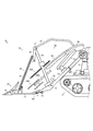
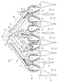
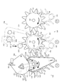
- the top view which shows the vicinity of the 2nd scraping device of the cutting part which concerns on one Embodiment of this invention, and a 3rd scraping device.
- the partial cross section top view which shows the 2nd picking device and 2nd upper conveying apparatus of the cutting part which concern on one Embodiment of this invention.
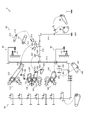
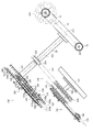
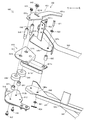
- the perspective view which shows the 2nd scraping apparatus and the 2nd upper conveying apparatus of the cutting part which concern on one Embodiment of this invention.
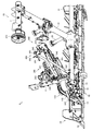
- the top view which shows the case where the holding
- the top view which shows the case where the clogging cancellation
- the traveling unit 2 is supported by a pair of left and right traveling crawlers 3.
- a mowing unit 4 that takes in the cereal grains in the field while mowing is attached to the front part of the traveling unit 2 so as to be adjustable up and down.
- a threshing unit 5 for threshing the cereals harvested by the reaping unit 4 is disposed in the upper left part of the traveling unit 2.
- a sorting unit 6 that sorts the processed product threshed by the threshing unit 5 is disposed in the lower left portion of the traveling unit 2.
- a grain tank 7 that stores the grains selected by the selection unit 6 is disposed on the right side of the traveling unit 2.
- a discharge auger 8 for discharging the grains stored in the grain tank 7 to the outside is disposed at the right rear portion of the traveling unit 2.
- a driving unit 9 that operates each of the above-described units is disposed on the right front portion of the traveling unit 2.
- the cutting unit 4 includes a cutting frame 10, a weeding tool 30, a pulling device 40, a scraping device 100, a cutting device 50, and a conveying device 60.
- the cutting frame 10 is a main body of the cutting unit 4 that supports the weeding tool 30 and each of the devices.
- the cutting frame 10 includes a cutting input pipe 11, a vertical transmission pipe 12, a horizontal transmission pipe 13, a plurality of weed frames 14, 14..., A drive pipe 15, and a pulling vertical transmission pipe 16.
- the frame includes a pulling lateral transmission pipe 17, a plurality of pulling drive pipes 18, a connecting frame 19, and an intermediate conveyance transmission pipe 20.
- the cutting input pipe 11 is rotatably provided at the left front portion of the traveling unit 2 with its axial direction as the left-right direction.
- the longitudinal transmission pipe 12 extends downward from the right end portion of the cutting input pipe 11 in the front oblique direction, with its axial direction orthogonal to the axial direction of the cutting input pipe 11.
- the horizontal transmission pipe 13 extends in the left-right direction from the extending end of the vertical transmission pipe 12 with its axial direction as the left-right direction.
- Each weed frame 14 extends forward from the lateral transmission pipe 13 with its axial direction being generally the front-rear direction.
- a plurality of weeding frames 14, 14... are arranged in parallel in the left-right direction at appropriate intervals.
- the drive pipe 15 is horizontally mounted between the weeding frames 14 and 14 located on the outermost left and right sides with the axial direction of the drive pipe 15 being the left and right direction.
- the drive pipe 15 is positioned in front of the lateral transmission pipe 13 and is arranged in parallel with the lateral transmission pipe 13.
- the pulling vertical transmission pipe 16 extends from the left end portion of the horizontal transmission pipe 13 forward and obliquely upward with its axial direction orthogonal to the axial direction of the horizontal transmission pipe 13.
- the vertical connection frame extends from the right end portion of the horizontal transmission pipe 13 forward and obliquely upward, with its axial direction being orthogonal to the axial direction of the horizontal transmission pipe 13.
- the pulling horizontal transmission pipe 17 is horizontally mounted between the extending end portion of the pulling vertical transmission pipe 16 and the extending end portion of the vertical connection frame with the axial direction thereof being the left-right direction.
- Each pulling drive pipe 18 extends forward from the pulling lateral transmission pipe 17 with its axial direction being generally vertical. .. Are arranged in parallel in the left-right direction at predetermined intervals.
- the connecting frame 19 extends rearward from the left and right midway part of the pulling lateral transmission pipe 17 with its axial direction being generally the front-rear direction.
- the connection frame 19 is connected to the cutting input pipe 11 side of the longitudinal transmission pipe 12 at its extended end.
- the middle conveying transmission pipe 20 extends from the side of the horizontal transmission pipe 13 of the vertical transmission pipe 12 to the upper front obliquely.
- the weeding tool 30 is for separating (weeding) grain cereals in the field.
- the weeding tool 30 includes eight weeding boards 31, 31... (See FIG. 4). Each weed board 31 is formed such that its tip is narrowed. Each weed board 31 is attached to the front end portion of each weed frame 14 so that its tip faces forward.
- the pulling device 40 causes cereals after weeding.
- the pulling device 40 includes seven pulling cases 41 that support the tine-equipped chain 42 so as to be rotationally driven.
- the plurality of elevating cases 41 are arranged in an inclined shape with front, rear, and rear heights behind the weeding tool 30, and are arranged at appropriate intervals in the left-right direction.
- Each pulling case 41 is positioned between each weeding frame 14 and each pulling drive pipe 18 and supported by these.
- the scraping device 100 is for scraping the stock of cereals caused by the pulling device 40.
- the scraping device 100 is arranged behind the pulling device 40 in a slanted shape with a front, a rear, and a height.
- the scraping device 100 includes a first scraping device 110, a second scraping device 120, a third scraping device 130, and a fourth scraping device 140.
- These scraping devices 110 to 140 are arranged in a slanting shape at the front, rear, and rear height behind the pulling device 40, and are arranged at appropriate intervals in the left-right direction.
- the first stirrer 110 is composed of 7 cereal grains, and 2 cereal grains on the right side (first cereal casket 171 and 2 cereal pestle 172 counted from the right side, and 1 in FIGS. 4 and 5. Although only one strain is shown, the cereals of each row are designated as 171, 172, 173, 174, 175, 176, and 177 in order from the right column.
- the first raking device 110 includes a pair of left and right star-shaped raking wheels 111 and 112 and a pair of left and right rabbing belts 113 and 114.
- the first scraping device 110 is arranged on the rightmost side among the plurality of scraping devices 110 to 140.
- the scraper wheel 111 is arranged in an inclined shape with a front, a rear, and a height, and is provided to be rotatable around the rotation shaft 161.
- the take-up wheel 112 is arranged in an inclined shape with front, rear, and rear heights, and is provided to be rotatable around the rotation shaft 162.
- the picking wheel 111 and the picking wheel 112 are arranged so as to be adjacent to each other in the left-right direction and mesh with each other.
- the large-diameter pulley 115 is disposed above the picking wheel 111 and fixed to the rotating shaft 161 together with the picking wheel 111.
- the small-diameter pulley 116 is disposed on the right front side of the large-diameter pulley 115 and is provided so as to be rotatable with respect to the cutting frame 10. Then, the take-in belt 113 is wound around the large-diameter pulley 115 and the small-diameter pulley 116.
- a large-diameter pulley 117 is disposed above the picking wheel 112 and is fixed to the rotating shaft 162 together with the picking wheel 112.
- a small-diameter pulley 118 is disposed on the left front side of the large-diameter pulley 117 and is rotatably provided with respect to the cutting frame 10. Then, the take-up belt 114 is wound around the large-diameter pulley 117 and the small-diameter pulley 118.
- the scraping belt 113 and the scraping belt 114 are arranged so as to be adjacent to each other in the left-right direction, and between the belt surfaces facing each other, that is, the left outer surface of the scraping belt 113 and the right outer surface of the scraping belt 114.
- the distance between the two is stretched substantially in the front-rear direction so that the distance from the front gradually decreases from the front to the rear, that is, in a substantially square shape when viewed from the front.
- the second stirrer 120 is one side of the left and right center side of the seven cereals, and in this embodiment, the right side of the culm (the third culm 173 counted from the rightmost side). Is to stir up the stockholder.
- the second raking device 120 includes a single star-shaped raking wheel 121 and a single raking belt 122 with a protrusion.
- the second scraping device 120 is arranged on the left side of the first scraping device 110 on the left and right center side among the plurality of scraping devices 110 to 140.
- the scraper wheel 121 is arranged in an inclined shape with front and rear and height, and is provided to be rotatable around the rotation shaft 163.
- the take-up wheel 121 is located on the left side of the left take-in wheel 112 of the first take-up device 110 and is not meshed with the left take-in wheel 112.
- the large-diameter pulley 123 is disposed above the picking wheel 121 and fixed to the rotating shaft 163 together with the picking wheel 121.
- a small-diameter pulley 124 is disposed on the left front side of the large-diameter pulley 123 and is rotatably provided with respect to the cutting frame 10. Then, the take-up belt 122 is wound around the large diameter pulley 123 and the small diameter pulley 124.
- the take-up belt 122 is stretched substantially in the front-rear direction.
- a guide rod (not shown) is provided between the pick-up belt 122 and the pick-up belt 114 of the first pick-up device 110 so as to face the right outer surface of the pick-up belt 122 with a predetermined interval. Placed in.
- the third scraping device 130 is the remaining two of the left and right central three of the seven grains, and in this embodiment, the middle one and the left one of the grains (counting from the rightmost) 4th and 5th grain rice cakes 174 and 175).
- the third scraping device 130 includes a pair of left and right star-shaped scraping wheels 131 and 132 and a pair of left and right scraping belts 133 and 134 with protrusions.
- the third stirrer 130 is arranged on the left and right center side of the plurality of stirrers 110 to 140 and on the left side of the second scraper 120.
- the scraper wheel 131 is arranged in an inclined shape with front and rear and rear heights, and is provided so as to be rotatable around the rotation shaft 164.
- the take-up wheel 132 is arranged in an inclined shape with front and rear and rear heights, and is provided to be rotatable around the rotation shaft 165.
- the picking wheel 131 and the picking wheel 132 are arranged so as to be adjacent to each other in the left-right direction and mesh with each other.
- the scraping wheel 131 is located on the left side of the scraping wheel 121 of the second scraping device 120 and is arranged adjacent to the scraping wheel 121 in the left-right direction. That is, the picking wheel 131 is arranged so as to be sandwiched between the left picking wheel 132 and the right picking wheel 121. Then, the scraping wheel 131 is meshed with the scraping wheel 132 as described above, and is also meshed with the scraping wheel 121.
- the large-diameter pulley 135 is disposed above the picking wheel 131 and is fixed to the rotating shaft 164 together with the picking wheel 131.
- a small-diameter pulley 136 is disposed on the right front side of the large-diameter pulley 135 and is rotatably provided with respect to the cutting frame 10. Then, the take-in belt 133 is wound around the large diameter pulley 135 and the small diameter pulley 136.
- a large-diameter pulley 137 is disposed above the stirrer wheel 132 and is fixed to the rotating shaft 165 together with the stirrer wheel 132.
- a small-diameter pulley 138 is disposed on the left front side of the large-diameter pulley 137 and is rotatably provided with respect to the cutting frame 10. Then, the driving belt 134 is wound around the large diameter pulley 137 and the small diameter pulley 138.
- the scraping belt 133 and the scraping belt 134 are arranged so as to be adjacent to each other in the left-right direction, and between the belt surfaces facing each other, that is, the left outer surface of the scraping belt 133 and the right outer surface of the scraping belt 134.
- the distance between the two is stretched substantially in the front-rear direction so that the distance from the front gradually decreases from the front to the rear, that is, in a substantially square shape when viewed from the front.
- the fourth stirrer 140 stirs the stock of the left side 2 left side of the 7 side rice cakes (6th and 7th side rice cakes 176 and 177 counted from the right side).
- the fourth raking device 140 includes a pair of left and right star-shaped raking wheels 141 and 142 and a pair of left and right raking belts 143 and 144 with protrusions.
- the fourth scraping device 140 is arranged on the leftmost side of the plurality of scraping devices 110 to 140 and adjacent to the left of the third scraping device 130.
- the scraping wheel 141 is arranged in an inclined shape with front, lower, and rear heights, and is provided so as to be rotatable around the rotation shaft 166.
- the take-up wheel 142 is arranged in an inclined shape with front and rear and rear height, and is provided so as to be rotatable around the rotation shaft 167.
- the picking wheel 141 and the picking wheel 142 are arranged so as to be adjacent to each other in the left-right direction and mesh with each other.
- the large-diameter pulley 145 is arranged above the picking wheel 141 and fixed to the rotating shaft 166 together with the picking wheel 141.
- a small-diameter pulley 146 is disposed on the right front side of the large-diameter pulley 145 and is provided to be rotatable with respect to the cutting frame 10. Then, the take-in belt 143 is wound around the large diameter pulley 145 and the small diameter pulley 146.
- a large-diameter pulley 147 is disposed above the picking wheel 142 and fixed to the rotating shaft 167 together with the picking wheel 142.
- a small-diameter pulley 148 is disposed on the left front side of the large-diameter pulley 147 and is provided so as to be rotatable with respect to the cutting frame 10. Then, the take-in belt 144 is wound around the large diameter pulley 147 and the small diameter pulley 148.
- the scraping belt 143 and the scraping belt 144 are arranged so as to be adjacent to each other in the left-right direction, and between the mutually facing belt surfaces, that is, the left outer surface of the scraping belt 143 and the right outer surface of the scraping belt 144.
- the distance between the two is stretched substantially in the front-rear direction so that the distance from the front gradually decreases from the front to the rear, that is, in a substantially square shape when viewed from the front.
- the thickness of the scraping wheel 121 of the second scraping device 120 and the right scraping wheel 131 of the third scraping device 130 that meshes with the scraping wheel 121 Is set to be thicker than the thicknesses of the other scraping wheels 111, 112, 132, 141, 142. That is, the width in the axial direction of the rotation shaft 163 of the picking wheel 121 and the width in the axial direction of the rotation shaft 164 of the picking wheel 131 are respectively the other picking wheels 111, 112, 132, 141, and 142. Is set larger than the width in the axial direction of the rotating shafts 161, 162, 165, 166, and 167.
- the thickness of the scraping wheel 121 of the second scraping device 120 and the thickness of the right scraping wheel 131 of the third scraping device 130 are both set to the same thickness L1.
- the thicknesses of the other scraping wheels 111, 112, 132, 141, 142 are all set to the same thickness L2.
- the thickness L1 and the thickness L2 are in a relationship of L1> L2 where the thickness L1 is larger than the thickness L2.
- the scraping wheel 121 of the second scraping device 120 and the pair of left and right scraping wheels 131 and 132 of the third scraping device 130 are the first It arrange
- the lower surfaces of the picking wheel 121 and the picking wheels 131 and 132 are arranged at higher positions in the vertical direction than the upper surfaces of the picking wheels 111 and 112 and the picking wheels 141 and 142.
- the lower surface height of the scraping wheel 121 of the second scraping device 120 and the lower surface height of the right scraping wheel 131 of the third scraping device 130 are both set to the same lower surface height H1. .
- the lower surface height of the left raking wheel 132 of the third scraping device 130 is set to the lower surface height H2.
- the upper surface height of the scraping wheels 111 and 112 of the first scraping device 110 and the upper surface height of the scraping wheels 141 and 142 of the fourth scraping device 140 are both set to the same upper surface height H3.
- the lower surface heights H1 and H2 and the upper surface height H3 have a relationship of H1 and H2> H3 where the lower surface heights H1 and H2 are higher than the upper surface height H3.
- the cutting device 50 is scraped by the first scraping device 110, the second scraping device 120, the third scraping device 130, and the fourth scraping device 140 of the scraping device 100.
- the cereal grains are cut by the cutting blade 51 on the stock side.
- the cutting device 50 is disposed below the scraping device 100 in an inclined shape with a front, a rear, and a height.
- the conveying device 60 conveys the cereals cut by the cutting device 50 toward the threshing unit 5.
- the conveyance device 60 is arranged behind the pulling device 40 and from above the scraping device 100 and the cutting device 50 to the upper rear.
- the transport device 60 includes a lower transport device 200, an upper transport device 300, a vertical transport device 70, an auxiliary transport device 80, and a tip transport device 90.
- the lower transfer device 200 joins and harvests the harvested cereal stocks to the vertical transfer device 70.
- the lower transfer device 200 includes a first lower transfer device 210, a second lower transfer device 220, a third lower transfer device 230, and a fourth lower transfer device 240.
- the first lower conveying device 210 is connected to the stock of the two rows of grain straws 171 and 172 that have been scraped by the first scraping device 110, and the grain straws 173, 174, The stocks of 175, 176, and 177 are joined together, and the stocks of seven cereal grains 171, 172, 173, 174, 175, 176, and 177 are nipped and transported to the vertical transport device 70.
- the first lower transport device 210 is arranged in a slanted shape with a front low rear height behind the first scraping device 110 and the second scraping device 120, and from the vicinity of the first scraping device 110 toward the left oblique rear. It is extended.
- the first lower transfer device 210 includes a transfer chain 211, a driven sprocket 212 fixed to the rotating shaft 161, a drive sprocket 213, idle pulleys 214 and 215 provided on the left and right sides of the drive sprocket 213, and a drive.
- a tension pulley 216 provided on the right front side of the sprocket 213.
- the conveyance chain 211 is wound around a driven sprocket 212, a drive sprocket 213, idle pulleys 214 and 215, and a tension pulley 216.
- the first lower transport device 210 includes a guide plate 511 that guides the transport chain 211, a gripper 512 that grips the cereals between the transport chains 211, and guide springs 513 and 514 (FIG. 14). reference).
- the second lower transfer device 220 sandwiches and conveys the stock of the stalks 173 for the first strip scraped by the second scraping device 120 to the junction 182 with the first lower transfer device 210.
- the second lower conveying device 220 is arranged in a slanted shape with a front low and a rear height behind the second scraping device 120 and in front of the left side of the first lower conveying device 210.
- the first lower transfer device 210 extends rearward to the vicinity of the middle of the transfer.
- the merging portion 182 is a midway transfer portion of the first lower transfer device 210 and is positioned close to the second lower transfer device 220.
- the second lower transfer device 220 includes a transfer chain 221, a drive sprocket 223 fixed to the rotary shaft 163, two idle pulleys 224 and 225, and a tension pulley 226.
- the conveyance chain 221 is wound around the drive sprocket 223, the idle pulleys 224 and 225, and the tension pulley 226.
- the third lower transport device 230 sandwiches and transports the stocks of the two cereal grains 174 and 175 scraped by the third scraping device 130 to the junction 181 with the fourth lower transport device 240.
- the third lower transport device 230 is arranged in a slanted shape with a front, rear, and rear height behind the third scraping device 130 and in front of the right side of the fourth lower transport device 240.
- the lower transfer device 240 extends rearward to the vicinity of the middle of the transfer.
- the merging portion 181 is in the middle of the conveyance of the fourth lower conveyance device 240 and is positioned close to the third lower conveyance device 230.
- the third lower transfer device 230 includes a transfer chain 231, a driven sprocket 232 fixed to the rotary shaft 164, a drive sprocket 233, an idle pulley 234 provided on the left side of the drive sprocket 233, and a drive sprocket 233. And a tension pulley 235 provided in front of the.
- the conveyance chain 231 is wound around a driven sprocket 232, a drive sprocket 233, an idle pulley 234 and a tension pulley 235.
- the third lower transport device 230 includes a guide plate 531 for guiding the transport chain 231, a sandwiching basket 532 and a guide spring 533 for sandwiching the rice cake between the transport chains 231, and a guide basket 534 for guiding the rice cake. (See FIG. 14).
- the fourth lower transporting device 240 is a stock of the culm 174/175 that is conveyed while being sandwiched and transported by the third lower transporting device 230 to the stock of the stalks 176/177 of the two strips that have been scraped by the fourth scraping device 140.
- the formers are merged, and the stocks of the cereal grains 174, 175, 176, and 177 for the four strips are nipped and conveyed to the junction 183 with the first lower conveying device 210.
- the fourth lower transport device 240 is arranged in a slanting shape at the front, rear, and rear height behind the fourth scraping device 140, and is tilted rightward from the vicinity of the third scraping device 130 to the vicinity of the transport end portion of the fourth lower transport device 240. It extends toward the rear.
- the merging portion 183 is located at a position downstream of the intermediate conveyance portion of the first lower conveyance device 210 and close to the fourth lower conveyance device 240.
- the fourth lower transfer device 240 includes a transfer chain 241, a driven sprocket 242 fixed to the rotation shaft 167, a drive sprocket 243, a separation pulley 244 and an idle pulley 245 provided to the right of the drive sprocket 243. And a tension pulley 246 provided in front of the drive sprocket 243.
- the transport chain 241 is wound around a driven sprocket 242, a drive sprocket 243, a separation pulley 244, an idle pulley 245 and a tension pulley 246.
- the fourth lower transfer device 240 includes a guide plate 541 for guiding the transfer chain 241, and a holding rod 542 and guide springs 543 and 544 for holding the culm between the transfer chain 241 (see FIG. 14). ).
- the fourth lower transport device 240 includes a clogging release means 600 that changes the position of the separating pulley 244, an upper frame 545, a middle frame 546, and a lower frame 547 that support the clogging release means 600, the guide plate 541, and the like. (See FIG. 14).
- the fourth lower transfer device 240 is arranged on the left side of the vertical transmission pipe 12, that is, on the left side in the left-right direction of the combine 1 in plan view (FIG. 4).
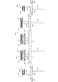
- the upper transfer device 300 is for locking and transporting the ear of the cereal that is nipped and transferred by the lower transfer device 200. As shown in FIG. 3, the upper transport device 300 is disposed above and below the lower transport device 200 in a front-rear and rear-inclined shape, and extends rearward from near the upper portion of the scraping device 100. As shown in FIG. 5, the upper transfer device 300 includes a first upper transfer device 310, a second upper transfer device 320, a third upper transfer device 330, and a fourth upper transfer device 340.
- the first upper transfer device 310 applies the tips of the cereal 173 transferred and locked from the second upper transfer device 320 to the tips of the two halves 171 and 172 conveyed by the first lower transfer device 210.
- the heads of the grain ridges 171, 172, and 173 for the three strips are locked and conveyed.
- the first upper transfer device 310 is disposed above the first lower transfer device 210 and extends from the vicinity of the first scraping device 110 toward the left oblique rear.
- the first upper transfer device 310 includes a transfer chain 311, a tine 312 attached to the transfer chain 311 so as to be able to protrude and house at a predetermined interval, a drive sprocket 313, and a tension pulley 314.
- the conveyance chain 311 is wound around the drive sprocket 313 and the tension pulley 314.
- the second upper transfer device 320 is configured to lock and transfer the tips of one grain of cereal 173 conveyed by the second lower transfer device 220 to the junction 192 with the first upper transfer device 310.
- the merging portion 192 is in the middle of the conveyance of the first upper conveyance device 310 and is positioned close to the second upper conveyance device 320.
- the third upper transport device 330 is configured to lock and transport the tips of the two cereal grains 174 and 175 transported by the third lower transport device 230 to the junction 191 with the fourth upper transport device 340.
- the merging portion 191 is in the middle of the transport of the fourth upper transport device 340 and is positioned close to the third upper transport device 330.
- the fourth upper transport device 340 is configured to hold the grain straws 174 and 175 conveyed from the third upper transport device 330 to the tips of the two grain straws 176 and 177 conveyed by the fourth lower transport device 240.
- the heads are joined, and the tips of the four cereal grains 174, 175, 176, and 177 are locked and conveyed to the junction 193 with the first upper conveyance device 310.
- the fourth upper transfer device 340 is disposed above the fourth lower transfer device 240 and extends from the vicinity of the fourth scraping device 140 toward the right rear side.
- the merging portion 193 is positioned downstream of the middle transfer portion of the first upper transfer device 310 and close to the fourth upper transfer device 340.
- the fourth upper transfer device 340 includes a transfer chain 341, a tine 342 attached to the transfer chain 341 so as to be able to protrude and house at a predetermined interval, a drive sprocket 343, a tension pulley 344, and idle pulleys 345 and 346. Is provided.
- the conveyance chain 341 is wound around the drive sprocket 343, the tension pulley 344, and the idle pulleys 345 and 346.
- the vertical conveyor 70 sandwiches and conveys the stock of seven cereal grains inherited from the conveyance terminal portion of the first lower conveyor 210 to the auxiliary conveyor 80.
- the vertical conveyance device 70 is arranged in a slanted shape at the front, rear, and rear height behind the lower conveyance device 200, and extends from the vicinity of the conveyance end portion of the lower conveyance device 200 toward the left diagonal rear. .
- the auxiliary conveyance device 80 is configured to nipping and conveying the stock of the 7 grain cereals inherited from the conveyance terminal portion of the vertical conveyance device 70 to the threshing unit 5.
- the auxiliary conveyance device 80 is disposed on the rear upper side of the vertical conveyance device 70, and extends backward from the vicinity of the conveyance end portion of the vertical conveyance device 70.
- the tip transport device 90 is a device that latches and transports the tips of the cereals that are transported by the first lower transport device 210, the vertical transport device 70, and the auxiliary transport device 80.
- the tip conveying device 90 is disposed below the rear portion of the first upper conveying device 310 and extends rearward from the vicinity of the middle of the conveying of the first upper conveying device 310 (see FIG. 5).
- a transmission shaft for transmitting power to each device is inserted along the longitudinal direction.
- a cutting input shaft 411 is inserted into the cutting input pipe 11.
- a longitudinal transmission shaft 412 is inserted into the longitudinal transmission pipe 12.
- a lateral transmission shaft 413 is inserted into the lateral transmission pipe 13.
- An intermediate conveyance transmission shaft 420 is inserted into the intermediate conveyance transmission pipe 20.
- the cutting input shaft 411 is linked to the engine mounted on the traveling unit 2 and linked to the longitudinal transmission shaft 412.
- the vertical transmission shaft 412 is appropriately interlocked and connected to the horizontal transmission shaft 413, the intermediate conveyance transmission shaft 420, and other transmission shafts. In this way, the power transmitted from the engine to the cutting input shaft 411 can be further transmitted from the cutting input shaft 411 to the pulling device 40, the scraping device 100, the cutting device 50, and the conveying device 60 via the vertical transmission shaft 412.
- the power extracted from the middle part of the vertical transmission shaft 412 is transmitted to the drive sprocket 213 of the first lower transfer device 210.
- the first lower transfer device 210 and the first scraping device 110 are sequentially driven by the power.
- the power extracted from the middle part of the vertical transmission shaft 412 is transmitted to the drive sprocket 313 of the first upper transport device 310.
- the first upper transport device 310 is driven by the power.
- the power extracted from the left end of the horizontal transmission shaft 413 is transmitted to the drive sprocket 243 of the fourth lower transport device 240.
- the fourth lower transfer device 240 and the fourth scavenging device 140 are sequentially driven by the power.
- the power extracted from the left end of the lateral transmission shaft 413 is transmitted to the drive sprocket 343 of the fourth upper transport device 340.
- the fourth upper transport device 340 is driven by the power.
- the cutting unit 4 drives each device with the power from the engine during the cutting operation, and takes in the cereals in the field while cutting. That is, in the cutting unit 4, the cereals after the weeding are caused after the cereals in the field are divided by the weeding tool 30 so as to be separated for each line. Subsequently, the stocker side of the cereal caused by the pulling device 40 is scraped by the scraping device 100.
- the scraping wheel 111 and the large-diameter pulley 115 rotate around the rotation shaft 161 in the direction of the arrow in FIG.
- the rotation of the large-diameter pulley 115 causes the take-up belt 113 to rotate.
- the picking wheel 111 the picking wheel 112 that meshes with the picking wheel 111 rotates around the rotation shaft 162 in the direction of the arrow in FIG.
- the large-diameter pulley 117 is rotated by the rotation of the scraping wheel 112.
- the take-up belt 114 rotates.
- the stock origin side of the grain halves 171 and 172 for the two right-hand sides is scraped backward by the scraping wheels 111 and 112 and the scraping belts 113 and 114.
- the scraping wheel 131 and the large-diameter pulley 135 rotate around the rotation shaft 164 in the direction of the arrow in FIG.
- the rotation of the large-diameter pulley 135 causes the take-up belt 133 to rotate.
- the picking wheels 121 and 132 meshing with the picking wheel 131 rotate around the rotation shafts 163 and 165 in the direction of the arrow in FIG. Due to the rotation of the scraping wheel 121, the large-diameter pulley 123 rotates in the direction of the arrow in FIG. Then, as the large-diameter pulley 123 rotates, the take-up belt 122 rotates.
- the large-diameter pulley 137 is rotated by the rotation of the scraping wheel 132. Then, as the large-diameter pulley 137 rotates, the take-up belt 134 rotates. As a result, the stock side of the grain 173 for the right one of the three right and left central sides is raked rearward by the picking wheel 121 and the picking belt 122, and the remaining one of the three left and right central sides is left. The stock side of the cereal grains 174 and 175 of the two strips is scraped backward by the scraping wheels 131 and 132 and the scraping belts 133 and 134.
- the scraping wheel 142 and the large-diameter pulley 147 rotate around the rotation shaft 167 in the arrow direction in FIG.
- the take-up belt 144 rotates.
- the picking wheel 142 the picking wheel 141 that meshes with the picking wheel 142 rotates around the rotation shaft 166 in the direction of the arrow in FIG.
- the large-diameter pulley 145 is rotated by the rotation of the scraping wheel 141.
- the take-in belt 143 rotates. Thereby, the stock origin side of the left side two cereal grains 176 and 177 is scraped backward by the scraping wheels 141 and 142 and the scraping belts 143 and 144.
- the cutting device 50 cuts the grains 171 and 172, the grains 173, the grains 174 and 175, and the grains 176 and 177 on the stock market side.
- the cereal grains 171, 172, cereal grains 173, cereal grains 174, 175, and cereal grains 176, 177 after the cutting are conveyed toward the threshing unit 5 while being merged on the way by the conveying device 60.
- the transport device 60 first, the stock side of the cereal baskets 171, 172, 173, 174, 175, and 176 177 are transported by the lower transport device 200, and the tip side is transported by the upper transport device 300. .
- the transport chain 231 is rotated by the rotation of the drive sprocket 233.
- the stock side of the two stalks 174 and 175 raked by the third rake device 130 is transported to the merging portion 181 on the upper side after the slant.
- the tip side of the two stalks 174 and 175 for which the stock source side is transported by the third lower transport device 230 is locked and transported to the junction 191 on the upper side after the slant.
- the transfer chain 241 is rotated by the rotation of the drive sprocket 243.
- the stock side of the cereal grains 176 and 177 of the two stalks raked by the fourth stirrer 140 and the stock side of the cereal grains 174 and 175 inherited by the merge part 181 are joined together at the upper part after the slant. It is conveyed to the part 183.
- the transport chain 341 is rotated by the rotation of the drive sprocket 343.
- the tip side of the two grain culms 176 and 177 conveyed by the fourth lower conveying device 240 is transferred to the tip side of the corn 174 and 175 that is locked and conveyed by the third upper conveying device 330.
- the tips of the grain ridges 174, 175, 176, and 177 for the four strips are latched and conveyed to the upper junction 193 after the diagonal.
- the transfer chain 221 is rotated by the rotation of the drive sprocket 223.
- the stock-source side of the grain scum 173 for one strip that has been scraped by the second scraping device 120 is conveyed to the rear upper junction 182.
- the tip side of the stalk 173 for one line that the stock source side is transported by the second lower transport device 220 is latched and transported to the rear upper junction 192.
- the transfer chain 211 is rotated by the rotation of the drive sprocket 213.
- the stock side of the two stalks 171 and 172 raked by the first stirrer 110 is conveyed upward after the slant and is inherited at the junctions 182 and 183, 173, 174, and 175 -It is conveyed to the vertical conveyance apparatus 70 with the stockholder side of 176 * 177.
- the transport chain 311 is rotated by the rotation of the drive sprocket 313.
- the tip side of the two cereal rice cakes 171 and 172 to which the stock source side is conveyed by the first lower conveying device 210 is combined with the ear of the cereal rice cake 173 inherited at the junction 192, and the third rice cake 171.
- the tips of 172 and 173 are locked and conveyed upward after the slant.
- the stock source side of the grain straws 174 and 175 transported by the third lower transport device 230 is the stock origin of the grain straws 176 and 177 transported by the fourth lower transport device 240 at the junction 181.
- the cereal baskets 174, 175, 176, and 177 that are being conveyed become one bundle for four strips, and the bundle is conveyed to the merge unit 183.
- the stocker side of the grain straws 171 and 172 transported by the first lower transporting device 210 joins the stocker side of the grain straw 173 transported by the second lower transporting device 220 at the joining part 182 and is being transported.
- Cereal grains 171, 172, and 173 form one bundle for three strips, and this bundle merges with the cereal grains 174, 175, 176, and 177 conveyed by the fourth lower conveying device 240 at the junction 183. In this way, the stock side of the seven cereal grains 171, 172, 173, 174, 175, 176, and 177 as one bundle is handed over to the conveying start end of the vertical conveying device 70.
- the tip side of the grain ridges 174 and 175 conveyed by the third upper conveying device 330 merges with the tip side of the grain 176 and 177 conveyed by the fourth upper conveying device 340 at the junction 191.
- the grains 174, 175, 176, and 177 being conveyed become one bundle of four strips, and this bundle is conveyed to the junction 193.
- the tip side of the grain pods 171 and 172 conveyed by the first upper conveying device 310 merges with the tip side of the corn 173 conveyed by the second upper conveying device 320 at the merging portion 192, and the corn candy being conveyed
- the bundles 171, 172, and 173 become one bundle of three strips, and this bundle joins the cereal grains 174, 175, 176, and 177 conveyed by the fourth upper conveyance device 340 at the junction 193.
- the tip side of the seven cereal grains 171, 172, 173, 174, 175, 176, and 177 as a bundle is transferred to the intermediate transfer portion of the tip transfer device 90.
- the conveyance start end part of the tip conveyance apparatus 90 is the downstream of the confluence
- the grain side 171, 172, 173, 174, 175, 176, and 177 of the 7 stalks are nipped and conveyed by the vertical conveying device 70 while the tip side is locked and conveyed by the tip conveying device 90, Finally, it is delivered to the threshing unit 5 via the auxiliary conveyance device 80.
- the transmission device 150 includes a chain 151, a drive sprocket 152, a driven sprocket 153, and a cover member 154.
- the drive sprocket 152 is fixed to the rotating shaft 163 together with the scraping wheel 121.
- the driven sprocket 153 is pivotally supported by a rotating shaft 155 that extends diagonally to the right of the drive sprocket 152 and extends in parallel with the rotating shaft 163.
- the chain 151 is wound around the drive sprocket 152 and the driven sprocket 153.
- the chain 151, the drive sprocket 152, and the driven sprocket 153 are covered with a substantially rectangular cover member 154.
- a columnar first transmission pipe 156 having a rotating shaft 163 inserted therein is projected from the front lower portion of the cover member 154.
- the transmission device 150 is supported by the second scraping device 120 via the first transmission pipe 156.
- a cylindrical second transmission pipe 157 having a rotating shaft 155 inserted therein is projected from the rear upper part of the cover member 154.
- the second upper transfer device 320 is supported by the transmission device 150 via the second transmission pipe 157.
- the second upper transfer device 320 includes a rotating plate 321, a plurality (four) of tines 322, 322, 322, 322, an upper plate 323, and a lower plate 324. And comprising.
- the rotating plate 321 is formed in a substantially disc shape.
- a rotating shaft 155 is inserted into the center of the rotating plate 321 and fixed to the rotating plate 321.
- one end portion (base portion 322 a, 322 a) of a substantially heave-shaped tine 322 is pivotally supported at a predetermined interval (approximately 90 °) in the circumferential direction around the rotating shaft 155. .
- the bases 322a and 322a of each tine are projected in the axial direction of the support shaft 322c and on the opposite side to the rotating plate 321.
- the upper plate 323 and the lower plate 324 are plate materials having a larger plate surface than the rotating plate 321.
- the upper plate 323 is disposed above the rotating plate 321 so as to be substantially parallel to the rotating plate 321 in a side view.
- the lower plate 324 is disposed below the rotating plate 321 so as to be substantially parallel to the rotating plate 321 in a side view.
- a rotation shaft 155 is inserted into the center portion of the upper plate 323 and the lower plate 324.
- the upper plate 323 is fastened to the lower plate 324 by bolts 325 and 325.
- a guide member for guiding one (upper) base portion 322a of the tine 322 is formed.
- the first guide member 323a is a part of the outer peripheral end (right side) of the upper plate 323, and protrudes in a strip shape toward the rotating plate 321 along the outer peripheral shape thereof.
- the second guide member 323b protrudes in a band shape toward the rotating plate 321 so as to have a substantially arc shape on the inner periphery slightly from the outer peripheral end.
- the third guide member 323c protrudes in a columnar shape from both ends in the longitudinal direction of the second guide member 323b toward the rotating plate 321.
- the second guide member 323b and the third guide member 323c are disposed at a position where one base portion 322a of the tine 322 is in sliding contact when the tine 322 rotates.
- first guide member 324a is a part of the outer peripheral end (right side) of the lower plate 324, and protrudes in a strip shape toward the rotating plate 321 along the outer peripheral shape thereof.
- the second guide member 324b protrudes in a band shape toward the rotating plate 321 so as to have a substantially arc shape on the inner periphery slightly from the outer peripheral end.
- the third guide member 324c protrudes in a columnar shape from both ends in the longitudinal direction of the second guide member 324b toward the rotating plate 321.
- the second guide member 324b and the third guide member 324c are disposed at a position where one base portion 322a of the tine 322 is slidably contacted when the tine 322 rotates.
- the first guide member 324a, the second guide member 324b, the second guide member 323b, the third guide member 323c, and the third guide member 324c are in the same position in plan view.
- the width between the first guide members 323a and 324a is set larger than the width of the tine 322 in the axial direction so that each tine 322 can pass in the axial direction of the rotation shaft 155.
- the drive sprocket 152 of the transmission device 150 is rotated by the rotation of the scraping wheel 121, and the driven sprocket 153 is rotated via the chain 151 wound around the drive sprocket 152.
- the rotation shaft 155 rotates.
- the rotating plate 321 rotates.
- the tine 322 attached to the rotating plate 321 rotates in the rotating direction of the rotating plate 321 about the support shaft 322c of the tine 322 when the base portions 322a and 322a come into contact with the third guide members 323c and 324c. .
- tip part 322b of the tine 322 protrudes outside the 1st guide member 323a * 324a (it protrudes in a substantially radial direction). Then, the base portions 322a and 322a of the tine 322 move between the first guide members 323a and 324a and the second guide members 323b and 324b, and the protruding state of the tine 322 is maintained. Thereafter, when the base portions 322a and 322a of the tine 322 are not brought into contact with the second guide members 323b and 323b, the distal end portion 322b of the tine 322 is located on the inner side than the first guide members 323a and 324a and on the outer side. The tine 322 is accommodated without protruding.
- the cover member 154 of the transmission apparatus 150 may serve as the guide rod of the corn straw to which it is conveyed.
- the harvesting unit 4 of the seven-row harvesting combine 1 is the harvesting of the combine 1 including the pulling device 40, the scraping device 100, the cutting device 50, and the conveying device 60.
- the scraping device 100 includes a first scraping device 110 that scrapes the right side two cereal grains 171 and 172 with a pair of left and right scraping wheels 111 and 112 and a scraping belt 113 and 114; A second scraping device 120 that scrapes the cereal bud 173 of one side out of the three strips on the left and right central sides with one scraping ring 121 and a scraping belt 122, a pair of left and right scraping wheels 131 and 132, and a scraper.
- the left side is the grain 176 ⁇
- a first upper transport device 310 that transports the tip of the cereal grains 171 and 172 that have been scraped by the first scraping device 110;
- the second upper transport device 320 that transports the tip of the grain culm 173 squeezed by the second scraping device 120 and the tip of the stalk 174 and 175 that is scratched by the third scoring device 130 are transported.
- a third upper transport device 330, and a fourth upper transport device 340 that transports the tips of the grains 176 and 177 scraped by the fourth scraping device 140, and power is supplied to the second upper transport device 320.
- To the second stirrer 120 from the third stirrer 130 It is to transfer to.
- the power transmission structure to the second upper transport device 320 is provided above the second stapling device 120. That is, a conventional transmission device for transmitting power to the second upper conveyance device 320 as in the prior art, in the vicinity of the merging portion where the cereal grains of the pieces being conveyed are merged by the conveyance device 60, specifically, the lower conveyance device It is not necessary to provide it in the vicinity of the merge part 182 where the stock side of the grain straws being conveyed by 200 joins or in the vicinity of the merge part 192 where the tips of the grain straws being conveyed by the upper conveyance device 300 meet. Therefore, the structure in the vicinity of the junction can be simplified, and clogging of the cereals in the vicinity of the junction can be suppressed. Further, the power transmission structure to the second upper transfer device 320 can be simplified.
- the second upper transfer device 320 can be sufficiently driven even when the power is transmitted from the scraping wheel 131 via the scraping wheel 121 and the transmission device 150.
- the scraping device 100 includes a single scraping wheel 121 of the second scratching device 120 and a scraping wheel 131 of the third scraping device 130 that meshes with the single scraping wheel 121. Is set to be thicker than the thicknesses of the other scraping wheels 111, 112, 132, 141, 142.
- the meshing may be disengaged and the transmission of power from the scraping wheel 131 to the single stirring wheel may be hindered.
- the single scraper wheel 121 and the scraper wheel 131 are thicker than the other scraper wheels 111, 112, 132, 141, and 142, so that they are difficult to disengage from each other. Therefore, power can be reliably transmitted from the scraping wheel 131 of the third scraping device 130 to the single scraping wheel 121 of the second scraping device 120, and eventually to the second upper transport device 320. It can be reliably transmitted from the batting device 130 via the second raking device 120.
- the scraping device 100 includes a single scraping wheel 121 of the second scraping device 120 and a pair of left and right scraping wheels 131 and 132 of the third scraping device 130. 110, a pair of left and right scraping wheels 111 and 112 and a pair of left and right scraping wheels 141 and 141 of the fourth scraping device 140 are arranged at higher positions.
- a single scraping wheel 121 of the second scraping device 120 and a pair of left and right scraping wheels 131 and 132 of the third scraping device 130 and a pair of left and right scraping wheels of the first scraping device 110 are arranged. It is possible to reduce the distance between each other while avoiding interference with 111 and 112. Also, a single scraper wheel 121 of the second scraper 120, a pair of left and right scrapers 131 and 132 of the third scraper 130, and a pair of left and right scrapers 141 of the fourth scraper 140. -The interference with 142 can be avoided and the distance between each other can be reduced.
- the single scraping belt 122 of the second scraping device 120 and the pair of left and right scraping belts 133 and 134 of the third scraping device 130 are connected to the left and right of the first scraping device 110.
- the pair of scrambling belts 113 and 114 and the pair of left and right scoring belts 143 and 144 of the fourth scoring device 140 are disposed at higher positions.
- the single scraping belt 122 of the second scraping device 120 and the pair of left and right scraping belts 133 and 134 of the third scraping device 130 and the pair of right and left of the first scraping device 110 are arranged.
- the interference with 144 can be avoided and the distance between each other can be reduced. Therefore, the space
- FIG. Thereby, power is allocated with good balance from the picking wheel 131 to the two picking wheels 121 and 132 arranged in parallel on the left and right sides of the picking wheel 131. Therefore, the load on each of the scraping wheels 121, 131, and 132 is distributed, and the failure rate of the second scraping device 120 and the third scraping device 130 can be reduced.
- the scraping wheel 121 of the second scraping device 120 and the right scraping wheel 131 of the third scraping device 130 are meshed and arranged in parallel, and the first transmitted by the power transmitted from the scraping wheel 121 is the first.
- the second lower transfer device 220 is configured to be driven.
- the transmission device for transmitting power to the second lower conveying device 220 as in the prior art is in the vicinity of the merging portion where the cereal grains being conveyed by the conveying device 60 are merged, specifically, the lower conveying
- the apparatus 200 does not have to be provided in the vicinity of the junction 182 where the stocker side of the grain culm being transported joins, or in the vicinity of the merger 192 where the tip of the grain cocoon being transported by the upper transport device 300 joins.
- the structure in the vicinity of the junction can be simplified, and clogging of the cereals in the vicinity of the junction can be suppressed.
- a transmission device such as a drive shaft that transmits power to the second lower conveyance device 220 is not necessary. That is, the power transmission structure to the second lower transfer device 220 can be simplified and the number of parts can be reduced.
- the scoring device 100 is configured to convey the cereal rice flour for the left and right central side into three parts on the right side and two on the left side, and convey it to the rear side.
- Swapping device 120 and third scrambling device 130 are reversed left and right
- second lower transport device 220 and third lower transport device 230 are interchanged left and right
- second upper transport device 320 and third upper transport device As a structure in which 330 is replaced, it is also possible to divide the left and right central three-row cereal into two pieces on the right side and one piece on the left side and transport it backward.
- a plurality of scoring devices having a pair of left and right scoring wheels and a scoring belt are arranged side by side to constitute a trimming part for even-numbered trimming, and a single scoring wheel and
- a power transmission mechanism to a single scraping device can be easily configured.
- the structure which transmits motive power from the meshed single picking wheel to the lower conveying apparatus which conveys the stock source of the single squeezed cereal and the upper conveying apparatus which conveys the tip these The power transmission structure to the lower transfer device and the upper transfer device can be simplified.
- the third upper transfer device 330 includes a transfer chain 331, a plurality of tines 332, 332,..., An upper plate 333, a lower plate 334, an auxiliary plate 335, a drive sprocket 336, an idle sprocket 337, a tension.
- a sprocket 338 and a tension adjusting mechanism 350 are provided.
- One end (base portion 332a, 332a) of tines 332, 332,..., Each having a substantially square shape is pivotally supported at the outer peripheral end of the conveyance chain 331 at predetermined intervals.
- the base portions 332a and 332a of the respective tines are projected in the axial direction of the support shaft 332c and on the side opposite to the conveyance chain 331.
- the upper plate 333 is disposed above the transport chain 331 and substantially parallel to the transport chain 331 in a side view.
- the lower plate 334 is disposed below the transfer chain 331 and substantially parallel to the transfer chain 331 in a side view.
- the upper plate 333 is fastened to the lower plate 334 by bolts and nuts 339 and the like.
- An auxiliary plate 335 is extended rightward from the rear portion of the lower plate 334.
- a guide member (a first guide member 333a, a second guide member 333b, and a third guide member 333c) for guiding one (upper) base portion 332a of the tine 332 is formed.
- the first guide member 333a is a part of the outer peripheral end (left side) of the upper plate 333, and protrudes in a strip shape toward the conveyance chain 331 along the outer peripheral shape thereof.
- the second guide member 333b is slightly inward from the outer peripheral end, and protrudes in a band shape from the rear part of the tension sprocket 338 to the intermediate part between the tension sprocket 338 and the idle sprocket 337 toward the transport chain 331.
- the third guide member 333c protrudes in a band shape from the rear part of the second guide member 333c to the middle part of the idle sprocket 337 toward the transport chain 331.
- the second guide member 333b and the third guide member 333c are disposed at a position where one base portion 332a of the tine 332 is slidably contacted when the tine 332 is rotated.
- first guide member 334a is a partial outer peripheral end (left side) of the lower plate 334, and protrudes in a belt shape toward the conveyance chain 331 along the outer peripheral shape thereof.
- the second guide member 334b is slightly inward from the outer peripheral end and protrudes in a belt shape from the rear part of the tension sprocket 338 to the intermediate part between the tension sprocket 338 and the idle sprocket 337 toward the transport chain 331.
- the third guide member 334c protrudes in a band shape from the rear part of the second guide member 334c to the middle part of the idle sprocket 337 toward the transport chain 331.
- the second guide member 334b and the third guide member 334c are disposed at a position where the other base portion 332a of the tine 332 is in sliding contact when the tine 332 rotates.
- the first guide member 334a, the second guide member 334b, the second guide member 333b, the third guide member 333c, and the third guide member 334c are in the same position in plan view.
- the width between the first guide members 333a and 334a is set larger than the width of the tine 332 in the axial direction so that each tine 332 can pass in the axial direction of the intermediate transport transmission shaft 420.
- the drive sprocket 336 is disposed above the auxiliary plate 335 and attached to the tip of the intermediate conveyance transmission shaft 420.
- the idle sprocket 337 is movably attached to the left side of the drive sprocket 336 between the upper plate 333 and the lower plate 334.
- the tension sprocket 338 is movably attached to the front of the idle sprocket 337 between the upper plate 333 and the lower plate 334.
- the tension sprocket 338 is configured to be movable in the longitudinal direction of the upper plate 333 and the lower plate 334 by a tension adjusting mechanism 350.
- the flanges 338 a and 338 a of the tension sprocket 338 constitute guide members that guide the base portions 332 a and 332 a of the tine 322.
- a transport chain 331 is wound around the drive sprocket 336, the idle sprocket 337, and the tension sprocket 338.
- the transport chain 331 rotates.
- the tine 332 attached to the conveyance chain 331 is moved in the rotation direction of the conveyance chain 331 around the support shaft 332c of the tine 332 when the base portions 332a and 332a abut against the flanges 338a and 338a of the tension sprocket 338. Rotate.
- tip part 332b of the tine 322 protrudes outward rather than the 1st guide member 333a * 334a (it protrudes in a substantially radial direction).
- the base portions 332a and 332a of the tine 332 are between the first guide members 333a and 334a and the flanges 338a and 338a, between the first guide members 333a and 334a and the second guide members 333b and 334b, and the first guide.
- the protruding state of the tine 322 is maintained by moving between the members 333a and 334a and the third guide members 333c and 334c. Thereafter, when the base portions 332a and 332a of the tine 332 are not brought into contact with the third guide members 333c and 334c, the distal end portion 332b of the tine 332 is located on the inner side than the first guide members 333a and 334a, and on the outer side. The tine 332 is stored without protruding.
- the second upper transport device 320 locks and transports the tip side of the culm 173 from the transport start end 370 to the transport end 371.
- the transport path 373 of the cereal 173 in the second upper transport device 320 is a path from the transport start end 370 to the transport end 371.
- the conveyance start end portion 370 is positioned at the right rear portion of the picking wheel 121 and is configured to be able to convey the tip side of the culm 173 being stirred by the picking wheel 121.
- the conveyance terminal portion 371 is a position in front of the midway portion in the longitudinal direction of the first upper conveyance device 310 or a position in front of the merging portion 192, and overlaps with the conveyance path of the grain straws 171 and 172 in the first upper conveyance device 310. And configured to eliminate conveyance leakage. Further, the second guide members 323b and 324b and the third guide members 323c and 324c are set so as to be the transfer start end portion 370 and the transfer end portion 371.
- the third upper transfer device 330 locks and conveys the tip side of the grain ridges 174 and 175 from the conveyance start end 380 to the conveyance end 381.
- the transport path 382 of the cereal buds 174 and 175 in the third upper transport apparatus 330 is a path from the transport start end portion 380 to the transport end portion 381.
- the conveyance start end portion 380 is positioned at the left rear portion of the picking wheel 131, and is configured to be able to convey the tip side of the grain straws 174 and 175 that are being picked up by the picking wheels 131 and 132.
- the conveyance end portion 381 is a position in front of the end portion in the longitudinal direction of the fourth upper conveyance device 340 or a position in front of the merging portion 191, and overlaps with the conveyance path of the cereal straws 176 and 177 in the fourth upper conveyance device 340. And configured to eliminate conveyance leakage. Further, the flanges 338a and 338a, the second guide members 333b and 334b, and the third guide members 333c and 334c are set so as to be the transfer start end portion 380 and the transfer end portion 381.
- the transport path 382 of the culm 174 and 175 in the third upper transport device 330 is configured to be longer than the transport path 373 of the culm 173 in the second upper transport device 320. Accordingly, in the third upper transport device 330, the transport chain is configured to be long as the transport path is long, and the number of tines pivotally supported by the transport chain and the number of sprockets wound around the transport chain are also increased. . In other words, the power required to drive the third upper transport device 330 is greater than the power required to drive the second upper transport device 320.
- the 3rd upper conveying apparatus 330 is set as the structure which conveys the grain cocoon for two strips, it is compared with the 2nd upper conveyance apparatus 320 of the structure which conveys the grain cocoon for one strip. As the number of grains to be conveyed increases, the power necessary for driving naturally increases. Further, in the third upper transport device 330, power is transmitted to the tine 332 via the transport chain 331, whereas in the second upper transport device 320, power is transmitted via the rotating plate 321. Since the transmission is made to the tine 322, the third upper transfer device 330 also increases the loss associated with the transmission of power and increases the power required for driving.
- an input pulley 410 to which engine power is input is fixed at the left end of the cutting input shaft 411, and a bevel gear is fixed at the right end.
- a bevel gear that meshes with the bevel gear is fixed to the rear end of the vertical transmission shaft 412.
- the right end of the cutting input shaft 411 is interlocked with the rear end of the vertical transmission shaft 412.
- a bevel gear is fixed to the front end of the vertical transmission shaft 412, and a bevel gear that meshes with the bevel gear is fixed to the middle portion of the horizontal transmission shaft 413.
- the front end of the vertical transmission shaft 412 is interlocked with the left and right middle portions of the horizontal transmission shaft 413.
- a bevel gear is fixedly provided at a front portion of the vertical transmission shaft 412, specifically, a position slightly behind the front end of the vertical transmission shaft 412, and is interlocked and connected to one end (lower side) of the intermediate conveyance transmission shaft 420 via the bevel gear.
- the A drive sprocket 233 of the third lower transfer device 230 is fixedly provided in the middle of the middle transfer transmission shaft 420 in the longitudinal direction. As described above, the drive chain 231 is wound around the drive sprocket 233 together with the driven sprocket 232.
- a drive sprocket 336 of the third upper transport device 330 is fixed to the other end (upper side) of the middle transport transmission shaft 420.
- the power transmitted from the engine to the input pulley 410 is transmitted to the intermediate conveyance transmission shaft 420 via the cutting input shaft 411 and the vertical transmission shaft 412.
- motive power is transmitted from the middle transport transmission shaft 420 to the stirrer 131 of the third stirrer 130 via the transport chain 231 of the third lower transporter 230.
- it is transmitted from the picking wheel 131 to the picking wheels 121 and 132 meshed with the picking wheel 131 to the left and right.
- the device 130 is driven.
- the upper transfer device that requires a large amount of power for driving out of the two upper transfer devices that convey three grains of the left and right central sides has a longer power transmission path.
- the structure further consumes power. Therefore, among the two upper transport devices that transport the left and right middle side cereal grains, the power transmission structure to the upper transport device with one long transport path is simplified, and the power transmission path is shortened and optimally configured. And the reaping part of the combine which can reduce motive power required for a drive and can convey a grain candy smoothly is provided.
- the harvesting unit 4 of the combine 1 is the harvesting unit 4 of the combine 1 including the pulling device 40, the scraping device 100, the cutting device 50, and the conveying device 60.
- the scraping device 100 includes a first scraping device 110 that scrapes the right side of the grain mash, a second scraping device 120 that scratches one side of the grain mash among the three left and right central strips, A third scoring device 130 for scrambling the remaining two grains among the left and right central three sections, and a fourth scoring apparatus 140 for scrambling the left two grains
- a single scraping wheel 121 of the scraping device 120 and a pair of left and right scraping wheels 131 and 132 of the third scraping device 130 are meshed in the left-right direction and arranged side by side.
- the power is transmitted from the vertical transmission shaft 412 extending obliquely forward and downward from the main body of the machine body through the intermediate transfer transmission shaft 420 erected from the front portion of the vertical transmission shaft 412.
- It is an upper transport device that transmits to the left and right central scraping wheels 131 among the insert wheels 121, 131, and 132 and has a long transport path among the second upper transport device 320 and the third upper transport device 330. What is transmitted to the third upper transfer device 330 A.
- the middle transport transmission shaft 420 is provided to the third upper transport device 330, which is the upper transport device having a long transport path and a large power required for driving, among the second upper transport device 320 and the third upper transport device 330. Therefore, the power transmission path from the vertical transmission shaft 412 to the third upper transport device 330 can be shortened. Thereby, the motive power required for a drive can be reduced, the said 3rd upper conveyance apparatus 330 operate
- power is transmitted to the scraping wheel 121 to the second scraping device 120 and the third scraping device 130 and then transmitted from the scraping wheel 121 to the scraping wheel 132 via the scraping wheel 131.
- the power transmission path is configured to be short. Can do.
- the power transmission path from the vertical transmission shaft 412 to the second scraping device 120 and the third scraping device 130 can be configured to be short.
- the power required for driving can be reduced, and the second scraping device 120 and the third scraping device 130 can operate appropriately to scrape the grains 173, 174, and 175 smoothly.
- the third upper transport device 330 is directly driven from the middle transport transmission shaft 420, whereas the second upper transport device 320 includes the middle transport transmission shaft 420, the transport chain 231, the scraper wheel 131, and the scraper. It is driven via the wheel 121 and the transmission device 150 (see FIG. 7).
- the power transmission path of the upper transport device (third upper transport device 330) that transports two grains of cereals is long, and the power transmission path of the upper transport device (second upper transport) that transports one crop of cereals.
- the apparatus 320) is configured to be shorter than the power transmission path of the apparatus 320) so that the power necessary for driving each upper transfer apparatus is made as uniform as possible, and the maintenance time due to uneven wear or the like is as much as possible. ing.
- the third upper transport device 330 is configured to extend to the rear end portion of the fourth upper transport device 340, and the second upper transport device 320 is configured to extend to the midway portion in the longitudinal direction of the first upper transport device 310.
- the 3rd upper conveyance apparatus 330 is the junction part 193 where the grain straws 171 * 172 currently conveyed by the 1st upper conveyance apparatus 310 and the grain straws 176 * 177 currently conveyed by the 4th upper conveyance apparatus 340 merge. It is configured to convey to a position close to, so that the grains 174 and 175 being conveyed can be conveyed in a long and stable posture.
- the 2nd upper conveyance apparatus 320 comprises the conveyance path
- the guide trough 360 guides the grain troughs 171, 172, and 173 being locked and transported by the first upper transport device 310 to the junction 193, and the fourth upper transport device 340.
- the grains 174, 175, 176, and 177 that are in the locked state are guided to the junction 193.
- the guide rod 360 is configured by bending a round bar-like member into a generally square shape in plan view, and both ends thereof are further curved inward.
- a right tip portion 360a, a first guide portion 360b, a second guide portion 360c, and a left tip portion 360d are sequentially arranged from the right side.
- the right front end portion 360a is attached to the second upper transport device 320 via the first connecting member 361. That is, the first connecting member 361 is formed in a substantially rectangular shape in plan view, and the outer peripheral end in the short direction is attached integrally with the outer peripheral end of the right tip portion 360a.
- the first connecting member 361 is provided with two mounting holes at an appropriate interval in the longitudinal direction.
- the first connecting member 361 is placed on the upper plate 323 of the second upper transport device 320, and a bolt 325 is inserted into one (the right end portion side) mounting hole, and the upper plate 323 and the lower plate are inserted. 324 is fastened together.
- the first connecting member 361 is attached to the central conveyance support pipe 21.
- the central transport support pipe 21 extends forward and downward from the left and right midway part of the pulling lateral transmission pipe 17, and a connecting part 21 a is formed in the right direction from the upper and lower midway part of the central transport support pipe 21.
- the connecting portion 21a is provided with a mounting hole, and a bolt 363 is inserted into the mounting hole and the other mounting hole (on the opposite right end portion side) of the first connecting member 361.
- a connecting member 361 is attached to the central conveyance support pipe 21.
- the 1st guide part 360b guides the grains 171 * 172 * 173 currently conveyed with the 1st upper conveyance apparatus 310 (including the tip conveyance apparatus 90) to the junction part 193.
- the first guide portion 360b is disposed to face the first upper transport device 310 in substantially parallel to the first upper transport device 310 in plan view.
- the second guide unit 360c guides the cereal grains 174, 175, 176, and 177 being conveyed by the fourth upper conveyance device 340 to the junction unit 193.
- the second guide portion 360c is disposed to face the fourth upper transport device 340 substantially in parallel with the fourth upper transport device 340 in plan view.
- the left tip 360d is attached to the third upper transport device 330 via the second connecting member 362. That is, the second connecting member 362 is formed in a substantially square shape in plan view, and the outer peripheral end thereof is integrally attached to the outer peripheral end of the left distal end portion 360d.
- a mounting hole is formed in the second connecting member 362, and a projecting member 333d projecting vertically from the upper plate 333 of the third upper transport device 330 is inserted into the mounting hole.
- a front end portion 360 d is attached to the upper plate 333 of the third upper transport device 330.
- the guide rod 360 is constructed between the second upper transport device 320 and the third upper transport device 330.
- the second upper transporting device 320 is provided with the guide trough for guiding the cereal straws 171, 172, and 173 being transported by the first upper transporting device 310 to the merging portion 193 of the cereal straw,
- the three upper conveying device 330 is provided with a guide rod that guides the grain ridges 174, 175, 176, and 177 being conveyed by the fourth upper conveying device 340 to the junction 193, and these two guide rods are integrated with each other. It is composed.
- the integrally formed guide rod 360 also serves as a support rod, and the second upper transport device 320 and the third upper transport device 330 support each other via the guide rod 360.
- shakiness of the 2nd upper conveyance apparatus 320 and the 3rd upper conveyance apparatus 330 can be suppressed, and the grain straws 173 * 174 * 175 can be conveyed smoothly.
- the cereal grains 171, 172, and 173 that are locked and conveyed by the first upper conveyance apparatus 310 and the tip conveyance apparatus 90 are guided to the junction section 193 along the first guide section 360b of the guide bowl 360.
- the grain baskets 174, 175, 176, and 177 being locked and conveyed by the fourth upper conveyance device 340 are guided to the junction part 193 along the second guide part 360 c of the guide basket 360.
- the guide rod 360 is not cut, the grains 171, 172, 173, 174, 175, 176, and 177 being transferred by the first upper transfer device 310 and the fourth upper transfer device 340 are caught in the cut. And the clogging of the cereal grains at the junction 193 can be suppressed.
- the harvesting unit when the harvesting unit has a plurality of merging units in the lower transport device, if each merging unit is provided with a clogging releasing unit, it is necessary to operate the clogging releasing unit for each merging unit. For this reason, when cereals are simultaneously jammed in a plurality of merging sections, the operator needs to operate the clogging release means for each merging section in order to remove the cereals, which is disadvantageous in that the work is complicated. Met. Then, the harvesting part of the combine which can remove easily the grain candy jammed in the confluence
- the upper frame 545 is formed by bending a cylindrical member in the middle.
- One end (rear end) of the upper frame 545 is disposed in the vicinity of the idle pulley 245 (the front end of the vertical conveyance device 70).
- the other end (front end) of the upper frame 545 is fixed to the weed frame 14 arranged on the leftmost side (see FIG. 16).
- An upper frame plate 548 is fixed to one end portion of the upper frame 545 toward the right side (extends to the joining portion 183 side).
- the middle frame 546 is an elongated plate-like member. A midway portion in the longitudinal direction of the middle frame 546 is connected to the upper frame 545 via a connecting member 549.
- the lower frame 547 is formed by bending a cylindrical member in the middle. One end (rear end) of the lower frame 547 is fixed to a lower portion of one end (rear end) of the middle frame 546 (see FIG. 16). The other end (front end) of the lower frame 547 is fixed to the lateral transmission pipe 13 (see FIG. 16).
- the clogging release means 600 includes a bracket 610, a rotation fulcrum shaft 620, a separating pulley shaft 630, an idle pulley shaft 640, a holding mechanism 650, and the like.
- the bracket 610 supports the separation pulley 244 and the idle pulley 245 so as to be rotatable.
- the bracket 610 includes an upper bracket 611 and a lower bracket 612.
- the upper bracket 611 is formed by bending or welding a plurality of plate materials. On one end (front end) side of the upper bracket 611, a pivot fulcrum hole 611a penetrating the upper bracket 611 in the vertical direction is formed. Further, on the other end (rear end) side of the upper bracket 611, a through hole 611b and a through hole 611c penetrating the upper bracket 611 in the vertical direction are formed side by side. A guide plate 611 d for guiding the conveyance chain 241 is fixed to the right side portion of the upper bracket 611.
- the lower bracket 612 is formed of a plate material.
- a guide spring 514 is fixed to the lower surface of the lower bracket 612.
- a through hole 612a and a through hole 612b that penetrate the plate surface of the lower bracket 612 are formed.
- the rotation fulcrum shaft 620 serves as a rotation fulcrum for the bracket 610.
- the rotation fulcrum shaft 620 is formed in a cylindrical shape.
- the rotation fulcrum shaft 620 is inserted into the rotation fulcrum hole 611a of the upper bracket 611 so as to be relatively rotatable.
- the lower end of the rotation fulcrum shaft 620 is in contact with the upper surface of the middle frame 546, and the upper end of the rotation fulcrum shaft 620 is in contact with the lower surface of the upper frame plate 548.
- the headed pin 621 is inserted through the flat washer 622, the through hole 548a formed in the upper frame plate 548, the pivot fulcrum shaft 620, the through hole 546a formed in the middle frame 546, and the flat washer 623 in this order.
- the rotation fulcrum shaft 620 is supported.
- the headed pin 621 is prevented from falling upward.
- Rotating fulcrum shaft 620 is arranged on the upstream side of merging portion 181 and merging portion 183 in the cereal conveying path by fourth lower conveying device 240 in plan view (FIG. 14).
- route of the grain straw by the 4th lower conveyance apparatus 240 means the locus
- the fact that the rotation fulcrum shaft 620 is arranged upstream of the merge portion 181 and the merge portion 183 means that the rotation fulcrum shaft 620 is perpendicular to the cereal conveyance path (see the dashed line X in FIG. 14). ) Means that the merging portion 181 and the merging portion 183 are located on the rear side in the transport direction from the perpendicular.
- the separation pulley shaft 630 serves as a rotation fulcrum of the separation pulley 244.
- the separation pulley shaft 630 is inserted through the through hole 611 b of the upper bracket 611, the separation pulley 244, and the spacer 631 in order.
- the lower end of the separating pulley shaft 630 is in contact with the lower bracket 612.
- the separating pulley shaft 630 is fixed to the lower bracket 612 by a bolt 632 inserted through the through hole 612a from below the lower bracket 612.
- the idle pulley shaft 640 serves as a rotation fulcrum of the idle pulley 245.
- the idle pulley shaft 640 is inserted through the through hole 611c of the upper bracket 611, the idle pulley 245, and the spacer 641 in this order.
- the lower end of the idle pulley shaft 640 is in contact with the lower bracket 612.
- the idle pulley shaft 640 is fixed to the lower bracket 612 by a bolt 642 inserted through the through-hole 612b from below the lower bracket 612.
- the holding mechanism 650 holds the rotation position of the bracket 610 at a predetermined position.
- the holding mechanism 650 includes an operation lever 651, a regulating member 652, a pin 653, and the like.
- the operation lever 651 is operated by an operator when changing the rotation position of the bracket 610.
- the operation lever 651 is formed of a plate material.
- a protrusion 651b that protrudes forward is formed in the front part of the operation lever 651 and in the middle of the left and right.
- a through hole 651 c that penetrates the plate surface of the operation lever 651 is formed at the right end of the operation lever 651.
- An elongated hole 651 d that penetrates the plate surface of the operation lever 651 is formed in the middle of the left and right of the operation lever 651.
- the long hole 651d is formed along an arc centered on the through hole 651c.
- the bolt 633 is inserted into the through hole 651c from above, and the bolt 633 is fastened to the upper end of the separating pulley shaft 630 with a predetermined fastening force.
- the operation lever 651 is supported so as to be rotatable about the separating pulley shaft 630.
- a bolt 643 is inserted into the long hole 651d from above, and the bolt 643 is fastened to the upper end of the idle pulley shaft 640 with a predetermined fastening force.
- the operation lever 651 is fastened to the upper ends of the separating pulley shaft 630 and the idle pulley shaft 640 by bolts 633 and 643, thereby preventing the upper bracket 611 from falling off. That is, the upper bracket 611 and the lower bracket 612 are connected by the separating pulley shaft 630 and the idle pulley shaft 640.
- the regulating member 652 is formed by bending a plate-like member into an L shape in plan view (FIG. 14).
- the restricting member 652 is erected on the rear ends of the upper frame 545 and the upper frame plate 548.
- One bent portion of the restricting member 652 extends obliquely in the front-rear direction substantially parallel to a line connecting the axis of the rotation fulcrum shaft 620 and the axis of the floating pulley shaft 640, and comes into contact with the protrusion 651b. It is a surface.
- the other bent portion of the restricting member 652 extends obliquely in the left-right direction and is a surface that comes into contact with the front surface of the grip portion 651a.
- the restricting member 652 can also be used as a connecting member that connects the upper frame 545 and the upper frame plate 548 to members such as other frames.
- the pin 653 regulates the rotation of the operation lever 651.
- the pin 653 is inserted through a pin hole 545 a formed at the rear end portion of the upper frame 545.
- the tip (lower end) of the pin 653 inserted through the pin hole 545a protrudes downward from the upper frame 545.
- the operation lever 651 when performing the cutting operation by the cutting unit 4, the operation lever 651 is rotated clockwise with respect to the bracket 610, and the protrusion 651 b of the operation lever 651 is moved to the right with respect to the restriction member 652. It is locked from the direction. In this state, an urging force is applied to the bracket 610 in the direction of clockwise rotation in plan view due to the tension of the transport chain 241. However, since the operation lever 651 is locked to the restriction member 652, the bracket 610 is held at a position protruding rightward by a predetermined amount with respect to the upper frame 545 without rotating clockwise in plan view. .
- the separating pulley 244 is held at a position close to the joining portion 183 and the joining portion 181.
- the position of the separating pulley 244 is defined as a work position.
- the pin 653 is provided in the pin hole 545a of the upper frame 545.
- the portion that is inserted and protrudes downward from the pin hole 545a of the pin 653 contacts the operation lever 651 from the rear. That is, the rotation of the operation lever 651 in the counterclockwise direction is restricted by the pin 653. Accordingly, the operation lever 651 can be reliably locked to the restricting member 652, and the separation pulley 244 can be moved to the working position even when the tension of the transport chain 241 or other external force is applied to the clogging release means 600. Can be held in.
- the operator grasps the grip portion 651a of the operation lever 651 from the left side of the cutting unit 4, and rotates the operation lever 651 counterclockwise in plan view.
- the locking between the protruding portion 651b of the operation lever 651 and the regulating member 652 is released. That is, the bracket 610 can be rotated clockwise in plan view.
- the operator operates the operation lever 651 while holding the grip portion 651a of the operation lever 651 in the state where the operation lever 651 is rotated to the maximum extent within the range limited by the long hole 651d.
- the lever 651 is pulled toward the left side of the cutting unit 4.
- the bracket 610 connected to the operation lever 651 via the separating pulley shaft 630 rotates about the rotation fulcrum shaft 620 clockwise in plan view.
- the rotation fulcrum shaft 620 serving as the rotation fulcrum of the bracket 610 is disposed on the upstream side of the conveyance path from the merging portion 181 and the merging portion 183. Therefore, the separating pulley 244 is separated from the joining portion 183 and the joining portion 181.
- the position of the separation pulley 244 is defined as a separation position.
- the separation pulley 244 When the separation pulley 244 is changed to the separation position, the space between the conveyance chain 241 and the conveyance chain 231 in the junction 183 and the space between the conveyance chain 241 and the conveyance chain 211 in the junction 181 are separated. This is wider than when the pulley 244 is in the working position. As a result, the cereals clogged in the merging portion 183 and the merging portion 181 can be easily removed.
- the operator rotates the operation lever 651 in the clockwise direction in the plan view as much as possible within a range limited by the long hole 651d.
- the protruding portion 651b of the operation lever 651 and the regulating member 652 are locked.
- the cutting unit 4 of the combine 1 includes the pulling device 40, the scraping device 100, the cutting device 50, the lower transport device 200, the upper transport device 300, and the vertical transport device 70.
- the lower conveying device 200 includes a third lower conveying device 230 that conveys one or two cereal grains on the central left side to the merging portion 181, and one or two central right conveying items.
- a second lower conveying device 220 that conveys the portion of the cereal to the merging portion 182, the left cereal or two halves of the cereal, and the cereal from the third lower conveying device 230 that is merged at the merging portion 181
- sets of the right side, the cereals from the 2nd lower conveyance apparatus 220 merged in the junction part 182, and the junction part 183 Combined fourth lower transfer
- the first lower transport device 210 that transports the cereals from the device 240 to the transport start end of the vertical transport device 70, and the fourth lower transport device 240 is disposed so as to face the merge portion 181 and the merge portion 183.
- the positions of the plurality of rotating wheels including the separating pulley 244, the conveying chain 241 for conveying the cereal wrapped around the plurality of rotating wheels, and the separating pulley 244 are close to the joining portion 181 and the joining portion 183.
- And clogging release means 600 that can be changed between the working position to be moved and the separated position to be separated from the merging portion 181 and the merging portion 183.
- the clogging release means 600 is provided so as to be rotatable with respect to the main body of the cutting unit 4, and holds the rotation position of the bracket 610 by holding the rotation position of the bracket 610 with the bracket 610 rotatably supporting the separation pulley 244.
- a holding mechanism 650 that holds the pulley 244 in the working position, and the pivot fulcrum (the pivot fulcrum shaft 620) of the bracket 610 is located upstream of the junction 183 of the fourth lower conveyor 240. Is to be placed.
- the bracket 610 is rotated in a direction away from the merge portion 181 and the merge portion 183.
- the distance between the fourth lower conveyance device 240 and the first lower conveyance device 210 and the distance between the fourth lower conveyance device 240 and the third lower conveyance device 230 are greater than the merge portion 183.
- the fourth lower transport device 240 is disposed on the opposite side to the operation unit 9 disposed on the combine 1, that is, on the left side of the combine 1.
- the clogging release means can be operated from the side opposite to the driving unit 9 by disposing the fourth lower transfer device 240 on the side opposite to the driving unit 9. Thereby, when operating the clogging release means, the operation unit 9 does not get in the way, and the maintainability can be improved.
Landscapes
- Life Sciences & Earth Sciences (AREA)
- Environmental Sciences (AREA)
- Outside Dividers And Delivering Mechanisms For Harvesters (AREA)
Abstract
Description
まず、刈取部4により刈取作業を行う場合について説明する。
4 刈取部
100 掻込装置
110 第一掻込装置
120 第二掻込装置
121 掻込輪
130 第三掻込装置
131 掻込輪
132 掻込輪
140 第四掻込装置
181 合流部(第一合流部)
182 合流部(第二合流部)
183 合流部(第三合流部)
200 下部搬送装置
210 第一下部搬送装置(右下部搬送装置)
220 第二下部搬送装置(中右下部搬送装置)
230 第三下部搬送装置(中左下部搬送装置)
240 第四下部搬送装置(左下部搬送装置)
241 搬送チェン(無端帯)
244 離間用プーリ(離間用回転輪)
300 上部搬送装置
310 第一上部搬送装置
320 第二上部搬送装置
330 第三上部搬送装置
340 第四上部搬送装置
360 案内杆
412 縦伝動軸
420 伝動軸(中搬送伝動軸)
600 詰まり解除手段
610 ブラケット
650 保持機構
Claims (8)
- 引起装置と、掻込装置と、切断装置と、下部搬送装置と、上部搬送装置と、縦搬送装置と、を備えるコンバインの刈取部において、
前記掻込装置は、
左右一対の掻込輪及び掻込ベルトで右側2条分の穀稈を掻き込む第一掻込装置と、
単一の掻込輪及び掻込ベルトで左右中央側3条分のうち片側1条分の穀稈を掻き込む第二掻込装置と、
左右一対の掻込輪及び掻込ベルトで左右中央側3条分のうち残り2条分の穀稈を掻き込む第三掻込装置と、
左右一対の掻込輪及び掻込ベルトで左側2条分の穀稈を掻き込む第四掻込装置と、を備え、
前記第二掻込装置の単一の掻込輪と、前記第三掻込装置の掻込輪のうち前記単一の掻込輪と隣り合う掻込輪とを噛合し、
前記上部搬送装置は、
前記第一掻込装置で掻き込まれた穀稈の穂先を搬送する第一上部搬送装置と、
前記第二掻込装置で掻き込まれた穀稈の穂先を搬送する第二上部搬送装置と、
前記第三掻込装置で掻き込まれた穀稈の穂先を搬送する第三上部搬送装置と、
前記第四掻込装置で掻き込まれた穀稈の穂先を搬送する第四上部搬送装置と、を備え、
動力を、前記第二上部搬送装置に前記第三掻込装置から前記第二掻込装置を介して伝達することを特徴とするコンバインの刈取部。 - 前記掻込装置は、前記第二掻込装置の単一の掻込輪と、この単一の掻込輪と噛合する前記第三掻込装置の掻込輪との厚みを、他の前記掻込輪の厚みよりも厚く設定する請求項1に記載のコンバインの刈取部。
- 前記掻込装置は、前記第二掻込装置の単一の掻込輪及び前記第三掻込装置の左右一対の掻込輪を、前記第一掻込装置の左右一対の掻込輪及び前記第四掻込装置の左右一対の掻込輪よりも高い位置に配置することを特徴とする請求項1または請求項2に記載のコンバインの刈取部。
- 動力を、機体本体より斜め前下方に延出する縦伝動軸から、当該縦伝動軸の前部より立設する伝動軸を介して、前記第三掻込装置の掻込輪のうち前記第二掻込装置の単一の掻込輪と隣り合う掻込輪に伝達することを特徴とする請求項1に記載のコンバインの刈取部。
- 前記第二上部搬送装置に、前記第一上部搬送装置で搬送中の穀稈を、穀稈の合流部まで案内する案内杆を設け、
前記第三上部搬送装置に、前記第四上部搬送装置で搬送中の穀稈を、前記合流部まで案内する案内杆を設け、
これら二つの案内杆を一体的に構成することを特徴とする請求項1または請求項4に記載のコンバインの刈取部。 - 前記下部搬送装置は、
前記第三掻込装置で掻き込まれた穀稈の株元を第一合流部まで搬送する第三下部搬送装置と、
前記第二掻込装置で掻き込まれた穀稈の株元を第二合流部まで搬送する第二下部搬送装置と、
前記第四掻込装置で掻き込まれた穀稈の株元と、前記第一合流部で合流させた前記第二下部搬送装置からの穀稈の株元を第三合流部まで搬送する第四下部搬送装置と、
前記第一掻込装置で掻き込まれた穀稈の株元と、前記第二合流部で合流させた前記第二下部搬送装置からの穀稈の株元と、前記第三合流部で合流させた第四下部搬送装置からの穀稈の株元とを前記縦搬送装置の搬送始端部まで搬送する第一下部搬送装置と、を備え、
前記第四下部搬送装置は、
前記第一合流部及び第三合流部に臨むように配置される離間用回転輪を含む複数の回転輪と、
前記複数の回転輪に巻き掛けられる穀稈搬送用の無端帯と、
前記離間用回転輪の位置を、前記第一合流部及び前記第三合流部に近接させる作業位置と、前記第一合流部及び前記第三合流部から離間させる離間位置との間で変更することが可能な詰まり解除手段と、
を備えることを特徴とする請求項1に記載のコンバインの刈取部。 - 前記詰まり解除手段は、
刈取部本体に対して回動可能に設けられて、前記離間用回転輪を回転自在に支持するブラケットと、
前記ブラケットの回動位置を保持することにより、前記離間用回転輪を前記作業位置に保持する保持機構と、を備え、
前記ブラケットの回動支点を、前記第四下部搬送装置の前記第三合流部よりも搬送上流側に配置する請求項6に記載のコンバインの刈取部。 - 前記第四下部搬送装置は、
前記コンバインに配置される運転部に対して左右反対側に配置される請求項7に記載のコンバインの刈取部。
Priority Applications (2)
| Application Number | Priority Date | Filing Date | Title |
|---|---|---|---|
| KR1020127016602A KR101749034B1 (ko) | 2009-12-08 | 2010-03-12 | 콤바인의 예취부 |
| CN201080055405.5A CN102647899B (zh) | 2009-12-08 | 2010-03-12 | 联合收割机的收割部 |
Applications Claiming Priority (6)
| Application Number | Priority Date | Filing Date | Title |
|---|---|---|---|
| JP2009-278752 | 2009-12-08 | ||
| JP2009278752A JP5654231B2 (ja) | 2009-12-08 | 2009-12-08 | コンバインの刈取部 |
| JP2010015619A JP5654243B2 (ja) | 2010-01-27 | 2010-01-27 | コンバインの刈取部 |
| JP2010-015619 | 2010-01-27 | ||
| JP2010017395A JP5797880B2 (ja) | 2010-01-28 | 2010-01-28 | コンバインの刈取部 |
| JP2010-017395 | 2010-01-28 |
Publications (1)
| Publication Number | Publication Date |
|---|---|
| WO2011070802A1 true WO2011070802A1 (ja) | 2011-06-16 |
Family
ID=44145358
Family Applications (1)
| Application Number | Title | Priority Date | Filing Date |
|---|---|---|---|
| PCT/JP2010/054223 Ceased WO2011070802A1 (ja) | 2009-12-08 | 2010-03-12 | コンバインの刈取部 |
Country Status (3)
| Country | Link |
|---|---|
| KR (1) | KR101749034B1 (ja) |
| CN (1) | CN102647899B (ja) |
| WO (1) | WO2011070802A1 (ja) |
Cited By (3)
| Publication number | Priority date | Publication date | Assignee | Title |
|---|---|---|---|---|
| CN106034545A (zh) * | 2016-07-25 | 2016-10-26 | 河南科技大学 | 一种青稞茎穗分流收获用茎秆定向输送割台 |
| EP3143864A1 (de) * | 2015-09-18 | 2017-03-22 | CLAAS Hungaria Kft. | Erntevorsatz |
| CN110122057A (zh) * | 2019-05-21 | 2019-08-16 | 南京工程学院 | 一种扶持弹簧式麻类作物收割机 |
Families Citing this family (3)
| Publication number | Priority date | Publication date | Assignee | Title |
|---|---|---|---|---|
| CN103621256B (zh) * | 2013-12-03 | 2015-08-26 | 湖南农夫机电有限公司 | 半喂入式收割机的割台作物收集输送装置 |
| CN108551843B (zh) * | 2018-05-31 | 2023-09-15 | 河北省农业机械化研究所有限公司 | 谷物联合收获机 |
| JP7373928B2 (ja) * | 2019-06-27 | 2023-11-06 | 株式会社クボタ | コンバイン |
Citations (7)
| Publication number | Priority date | Publication date | Assignee | Title |
|---|---|---|---|---|
| JPH0140442Y2 (ja) * | 1982-07-29 | 1989-12-04 | ||
| JPH11253022A (ja) * | 1998-03-11 | 1999-09-21 | Iseki & Co Ltd | コンバイン |
| JP2003304723A (ja) * | 2003-04-14 | 2003-10-28 | Iseki & Co Ltd | 刈取搬送装置の掻込装置 |
| JP3968043B2 (ja) * | 2003-03-12 | 2007-08-29 | ヤンマー農機株式会社 | 刈取部の詰まり解除装置 |
| JP2009136190A (ja) * | 2007-12-05 | 2009-06-25 | Mitsubishi Agricult Mach Co Ltd | コンバイン |
| JP2009142173A (ja) * | 2007-12-12 | 2009-07-02 | Iseki & Co Ltd | 多条刈りコンバイン |
| JP2009142214A (ja) * | 2007-12-14 | 2009-07-02 | Iseki & Co Ltd | コンバインの刈取装置 |
Family Cites Families (2)
| Publication number | Priority date | Publication date | Assignee | Title |
|---|---|---|---|---|
| JPS58161429U (ja) * | 1982-04-21 | 1983-10-27 | 株式会社クボタ | 刈取機の茎稈導入部 |
| JP3445123B2 (ja) * | 1997-10-30 | 2003-09-08 | 株式会社クボタ | コンバインの刈取穀稈搬送装置 |
-
2010
- 2010-03-12 WO PCT/JP2010/054223 patent/WO2011070802A1/ja not_active Ceased
- 2010-03-12 KR KR1020127016602A patent/KR101749034B1/ko active Active
- 2010-03-12 CN CN201080055405.5A patent/CN102647899B/zh not_active Expired - Fee Related
Patent Citations (7)
| Publication number | Priority date | Publication date | Assignee | Title |
|---|---|---|---|---|
| JPH0140442Y2 (ja) * | 1982-07-29 | 1989-12-04 | ||
| JPH11253022A (ja) * | 1998-03-11 | 1999-09-21 | Iseki & Co Ltd | コンバイン |
| JP3968043B2 (ja) * | 2003-03-12 | 2007-08-29 | ヤンマー農機株式会社 | 刈取部の詰まり解除装置 |
| JP2003304723A (ja) * | 2003-04-14 | 2003-10-28 | Iseki & Co Ltd | 刈取搬送装置の掻込装置 |
| JP2009136190A (ja) * | 2007-12-05 | 2009-06-25 | Mitsubishi Agricult Mach Co Ltd | コンバイン |
| JP2009142173A (ja) * | 2007-12-12 | 2009-07-02 | Iseki & Co Ltd | 多条刈りコンバイン |
| JP2009142214A (ja) * | 2007-12-14 | 2009-07-02 | Iseki & Co Ltd | コンバインの刈取装置 |
Cited By (3)
| Publication number | Priority date | Publication date | Assignee | Title |
|---|---|---|---|---|
| EP3143864A1 (de) * | 2015-09-18 | 2017-03-22 | CLAAS Hungaria Kft. | Erntevorsatz |
| CN106034545A (zh) * | 2016-07-25 | 2016-10-26 | 河南科技大学 | 一种青稞茎穗分流收获用茎秆定向输送割台 |
| CN110122057A (zh) * | 2019-05-21 | 2019-08-16 | 南京工程学院 | 一种扶持弹簧式麻类作物收割机 |
Also Published As
| Publication number | Publication date |
|---|---|
| CN102647899A (zh) | 2012-08-22 |
| CN102647899B (zh) | 2015-09-02 |
| KR20120113741A (ko) | 2012-10-15 |
| KR101749034B1 (ko) | 2017-07-03 |
Similar Documents
| Publication | Publication Date | Title |
|---|---|---|
| CN102647899B (zh) | 联合收割机的收割部 | |
| JP4952571B2 (ja) | 多条刈りコンバイン | |
| JP2009153437A5 (ja) | ||
| JP2016015899A (ja) | コンバイン | |
| JP5125474B2 (ja) | コンバインの刈取装置 | |
| JP5797880B2 (ja) | コンバインの刈取部 | |
| JP5422523B2 (ja) | コンバインの刈取部 | |
| JP2009142214A5 (ja) | ||
| JP5654231B2 (ja) | コンバインの刈取部 | |
| JP5452129B2 (ja) | コンバイン | |
| JP5654243B2 (ja) | コンバインの刈取部 | |
| JP6437360B2 (ja) | コンバイン | |
| JP5468936B2 (ja) | コンバインの刈取部 | |
| JP5003468B2 (ja) | 多条刈りコンバインの刈取搬送装置 | |
| JP2009044991A (ja) | コンバイン | |
| JP5379542B2 (ja) | コンバインの刈取部 | |
| JP5463047B2 (ja) | 普通型コンバイン | |
| JP2011036167A (ja) | コンバイン | |
| JP4951999B2 (ja) | コンバイン | |
| JP2017055747A (ja) | コンバイン | |
| JP4524620B2 (ja) | コンバイン | |
| JP2017055748A (ja) | コンバイン | |
| JP2005218363A (ja) | コンバインの穀稈移送装置 | |
| JP4528647B2 (ja) | コンバイン | |
| JP5756613B2 (ja) | コンバイン |
Legal Events
| Date | Code | Title | Description |
|---|---|---|---|
| WWE | Wipo information: entry into national phase |
Ref document number: 201080055405.5 Country of ref document: CN |
|
| 121 | Ep: the epo has been informed by wipo that ep was designated in this application |
Ref document number: 10835725 Country of ref document: EP Kind code of ref document: A1 |
|
| NENP | Non-entry into the national phase |
Ref country code: DE |
|
| ENP | Entry into the national phase |
Ref document number: 20127016602 Country of ref document: KR Kind code of ref document: A |
|
| 122 | Ep: pct application non-entry in european phase |
Ref document number: 10835725 Country of ref document: EP Kind code of ref document: A1 |