WO2011065273A1 - 自動製パン器 - Google Patents
自動製パン器 Download PDFInfo
- Publication number
- WO2011065273A1 WO2011065273A1 PCT/JP2010/070541 JP2010070541W WO2011065273A1 WO 2011065273 A1 WO2011065273 A1 WO 2011065273A1 JP 2010070541 W JP2010070541 W JP 2010070541W WO 2011065273 A1 WO2011065273 A1 WO 2011065273A1
- Authority
- WO
- WIPO (PCT)
- Prior art keywords
- temperature
- bread
- container
- pulverization
- liquid absorption
- Prior art date
- Legal status (The legal status is an assumption and is not a legal conclusion. Google has not performed a legal analysis and makes no representation as to the accuracy of the status listed.)
- Ceased
Links
Images




Classifications
-
- A—HUMAN NECESSITIES
- A21—BAKING; EDIBLE DOUGHS
- A21C—MACHINES OR EQUIPMENT FOR MAKING OR PROCESSING DOUGHS; HANDLING BAKED ARTICLES MADE FROM DOUGH
- A21C13/00—Provers, i.e. apparatus permitting dough to rise
-
- A—HUMAN NECESSITIES
- A21—BAKING; EDIBLE DOUGHS
- A21B—BAKERS' OVENS; MACHINES OR EQUIPMENT FOR BAKING
- A21B7/00—Baking plants
- A21B7/005—Baking plants in combination with mixing or kneading devices
Definitions
- the present invention relates to an automatic bread maker mainly used in general households.
- an automatic bread maker for home use generally has a mechanism for producing bread by directly using a bread container into which bread ingredients are placed (see, for example, Patent Document 1).
- a bread container in which bread ingredients are placed is placed in a baking chamber in the main body.
- the bread raw material in a bread container is kneaded into bread dough with the kneading blade provided in a bread container (kneading process).
- a fermentation process for fermenting the kneaded bread dough is performed, and the bread container is used as a baking mold to bake the bread (baking process).
- flour rice, rice flour, etc.
- a mixed powder mixed with raw materials was needed.
- this bread manufacturing method first, cereal grains are mixed with a liquid, and the mixture is pulverized by a pulverizing blade (a pulverizing step). And the bread raw material containing the paste-form ground powder obtained through the crushing process is kneaded into dough (kneading process), and after the dough is fermented (fermentation process), the fermented dough is baked into bread. (Baking process).
- the present applicants have obtained knowledge that the pulverized powder obtained immediately after the pulverization process is too high in temperature and is not suitable for kneading into bread dough as it is. . For this reason, the method of providing a cooling device and starting the kneading process by lowering the temperature of the pulverized powder as soon as possible has been tried.
- the configuration in which the cooling device is provided has a problem that the cost of the automatic bread maker increases.
- an object of the present invention is to provide an automatic bread maker capable of producing a well-made bread from cereal grains at as low a cost as possible.
- an automatic bread maker of the present invention executes a bread manufacturing process in a state where a bread raw material is charged, a main body that receives the container, and the container is received in the main body.
- An automatic bread maker comprising: a control unit configured to cause the bread manufacturing process to include a pulverization process for pulverizing the grain grains in the container, and a pulverized powder of the grain grains pulverized by the pulverization process. And a liquid absorption step after pulverization to be liquefied.
- the bread manufacturing process includes a post-pulverization liquid absorption step in which liquid is absorbed into the pulverized grains.
- a post-pulverization liquid absorption step in which liquid is absorbed into the pulverized grains.
- the automatic bread maker configured as described above further includes a temperature detection unit capable of detecting at least one of an outside air temperature, a temperature of the container, a temperature around the container, and a temperature of the bread raw material in the container, and the control The unit preferably controls the time of the post-pulverization liquid absorption step based on the temperature detected by the temperature detection unit.
- pulverization is controlled based on the temperature (environment temperature) which influences the cooling rate of pulverized powder, or the temperature (temperature obtained directly or indirectly) of pulverized powder. Therefore, it is easy to adjust the temperature at the time when the liquid absorption process after pulverization is completed to the target temperature. That is, it is possible to suppress variation in temperature at the start of the kneading process performed after the liquid absorption process after pulverization, and it is easy to obtain a good bread.
- the temperature detection unit is provided so as to be able to detect the temperature of the container, and the control unit, when the temperature of the container reaches a predetermined temperature in the post-grinding liquid absorption step The liquid absorption step after pulverization may be terminated.
- the predetermined temperature is preferably set to a temperature at which the yeast works actively (for example, 28 ° C. to 30 ° C.).
- the temperature detection unit is provided so as to be able to detect the outside air temperature in addition to the temperature of the container.
- the temperature is higher than a predetermined temperature, it is preferable to end the liquid absorption step after pulverization when the temperature of the container reaches the outside air temperature.
- the control unit controls the post-pulverization liquid absorption step so that the time of the post-pulverization liquid absorption step is equal to or longer than a first time and within a second time, Even if it is determined that the liquid absorption process after pulverization can be completed based on information from the temperature detection unit, if the first time is not reached, the liquid absorption process after pulverization is not terminated, and the temperature Even when it is determined that the post-pulverization liquid absorption step cannot be completed based on information from the detection unit, it is preferable that the post-pulverization liquid absorption step is terminated when the second time is exceeded.
- the liquid absorption step after pulverization aims not only at obtaining the cooling period of the pulverized powder but also increasing the amount of fine particles in the pulverized powder. For this reason, it is preferable to adopt this configuration so that the liquid absorption time does not become too short. However, if the first time is set too long, the pulverized powder may be cooled too much, and the temperature at the start of the kneading process may become lower than necessary. In consideration of this point, it is preferable to determine the first time. Further, it may be assumed that it takes a very long time for the container temperature to fall to a predetermined temperature or the outside air temperature.
- the bread production time may be significantly increased and the user may feel inconvenient. For this reason, it is preferable to set the upper limit of the liquid absorption time so that the liquid absorption time does not become too long.
- the automatic bread maker configured as described above further includes a temperature detection unit capable of detecting at least one of an outside air temperature, a temperature of the container, a temperature around the container, and a temperature of the bread raw material in the container, and the control
- the unit is based on a liquid absorption time table in which the liquid absorption time is determined corresponding to the temperature, and a temperature detected before or after the cereal grain pulverization using the temperature detection unit.
- the liquid absorption time in the liquid absorption step after pulverization may be determined.
- the pulverized powder of grains can be sufficiently cooled and the temperature variation at the end of the liquid absorption process after pulverization can be achieved. Can be suppressed.
- the temperature detection unit detects the outside air temperature or the temperature around the container, the liquid absorption time can be determined based on the temperature detected after pulverization of the grain or before pulverization.
- the temperature detection unit detects the container temperature and the bread material temperature, the liquid absorption time can be determined based on the temperature detected before the pulverization of the grain.
- the liquid absorption process before pulverization for absorbing the liquid into the cereal grains in the container the pulverization process, the liquid absorption process after pulverization, and the cereal grains
- the kneading step of kneading the bread material in the container containing the pulverized powder of dough into the bread dough, the fermentation step of fermenting the kneaded bread dough, and the baking step of firing the fermented bread dough are performed sequentially and continuously. It is good as well.
- an automatic bread maker capable of producing a well-made bread from grain can be provided at low cost. For this reason, according to the present invention, bread production at home can be made more familiar.
- Vertical sectional view of the automatic bread maker of this embodiment 1 is a partially vertical sectional view of the automatic bread maker according to the present embodiment shown in FIG. 1 cut in a direction perpendicular to FIG.
- mixing blade The schematic plan view for demonstrating the structure of the grinding
- mixing blade The top view of the bread container in the automatic bread maker of this embodiment when the kneading blade is in the folded position Top view of bread container when kneading blade is in open position in automatic bread maker of this embodiment Schematic plan view showing the state of the clutch when the kneading blade is in the open position in the automatic bread maker of the present embodiment Control block diagram of automatic bread maker of this embodiment The schematic diagram which shows the flow of the bread-making course for rice grains in the
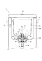
- FIG. 1 is a vertical sectional view of the automatic bread maker according to the present embodiment.
- 2 is a partial vertical sectional view of the automatic bread maker according to the present embodiment shown in FIG. 1 cut in a direction perpendicular to FIG.
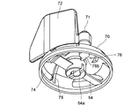
- FIG. 3 is a schematic perspective view for explaining the configuration of the crushing blade and the kneading blade provided in the automatic bread maker of the present embodiment, and is a view when seen obliquely from below.
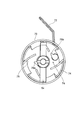
- FIG. 4 is a schematic plan view for explaining the configuration of the crushing blade and the kneading blade provided in the automatic bread maker of the present embodiment, and is a view seen from below.
- FIG. 1 is a vertical sectional view of the automatic bread maker according to the present embodiment.
- 2 is a partial vertical sectional view of the automatic bread maker according to the present embodiment shown in FIG. 1 cut in a direction perpendicular to FIG.
- FIG. 3 is a schematic perspective view for explaining the configuration of the crushing blade and the kneading blade provided
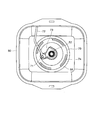
- FIG. 5 is a top view of the bread container when the kneading blade is in the folded position in the automatic bread maker of the present embodiment.
- FIG. 6 is a top view of the bread container when the kneading blade is in the open posture in the automatic bread maker of the present embodiment.
- the overall configuration of the automatic bread maker will be described mainly with reference to FIGS. 1 to 6.
- the left side in FIG. 1 is the front (front) of the automatic bread maker 1 and the right is the back (rear) of the automatic bread maker 1. Further, it is assumed that the left hand side of the observer facing the automatic bread maker 1 from the front is the left side of the automatic bread maker 1, and the right hand side is the right side of the automatic bread maker 1.
- the automatic bread maker 1 has a box-shaped main body 10 constituted by a synthetic resin outer shell.
- the main body 10 is provided with a U-shaped synthetic resin handle 11 connected to both ends of the left side surface and the right side surface thereof, whereby the automatic bread maker 1 is easily transported.
- An operation unit 20 is provided on the front surface of the main body 10.
- the operation unit 20 includes a group of operation keys such as a start key, a cancel key, a timer key, a reservation key, a selection key for selecting a bread production course (rice flour bread course, flour bread course, etc.),
- a display unit for displaying contents set by the operation key group, errors, and the like is provided.
- the display unit includes a liquid crystal display panel and a display lamp using a light emitting diode as a light source.
- the upper surface of the main body behind the operation unit 20 is covered with a lid 30 made of synthetic resin.
- the lid 30 is attached to the back side of the main body 10 with a hinge shaft (not shown), and is configured to rotate in a vertical plane with the hinge shaft as a fulcrum.
- the lid 30 is provided with a viewing window made of heat-resistant glass, and the user can look into the baking chamber 40 described later through the viewing window.
- a firing chamber 40 is provided inside the main body 10.
- the baking chamber 40 is made of sheet metal, and an upper surface is opened.
- the bread container 50 is put into the baking chamber 40 through the opening.
- the baking chamber 40 includes a peripheral side wall 40a and a bottom wall 40b having a rectangular horizontal section.
- a sheathed heater 41 is disposed so as to surround the bread container 50 accommodated in the baking chamber 40, and the bread raw material in the bread container 50 can be heated.
- a sheet metal base 12 is installed inside the main body 10.
- a bread container support 13 made of an aluminum alloy die-cast product is fixed at a location corresponding to the center of the firing chamber 40. The inside of the bread container support part 13 is exposed inside the baking chamber 40.
- a driving shaft 14 is vertically supported at the center of the bread container support 13.
- the pulleys 15 and 16 give rotation to the driving shaft 14. Clutchs are respectively disposed between the pulley 15 and the driving shaft 14 and between the pulley 16 and the driving shaft 14. Therefore, when the pulley 15 is rotated in one direction and the rotation is transmitted to the driving shaft 14, the rotation of the driving shaft 14 is not transmitted to the pulley 16, and the pulley 16 is rotated in the opposite direction to the pulley 15 to drive the driving shaft 14. When the rotation is transmitted to the pulley 15, the rotation of the driving shaft 14 is not transmitted to the pulley 15.
- the pulley 15 is rotated by a kneading motor 60 fixed to the base 12.
- the kneading motor 60 is a saddle shaft, and the output shaft 61 protrudes from the lower surface.
- a pulley 62 connected to the pulley 15 by a belt 63 is fixed to the output shaft 61. Since the kneading motor 60 itself is a low speed / high torque type, and the pulley 62 rotates the pulley 15 at a reduced speed, the driving shaft 14 rotates at a low speed / high torque.
- the pulley 16 is rotated by a crushing motor 64 that is also supported by the base 12.
- the grinding motor 64 is also a saddle shaft, and the output shaft 65 protrudes from the upper surface.
- a pulley 66 connected to the pulley 16 by a belt 67 is fixed to the output shaft 65.
- the crushing motor 64 plays a role of giving high-speed rotation to a crushing blade described later. Therefore, a high-speed rotating motor is selected as the grinding motor 64, and the reduction ratio between the pulley 66 and the pulley 16 is set to be approximately 1: 1.
- the bread container 50 is made of sheet metal and has a bucket-like shape, and a handle (not shown) for handbags is attached to the mouth edge.
- the horizontal section of the bread container 50 is a rectangle with rounded corners.
- the concave portion 55 is circular in a planar shape, and a gap 56 is provided between the outer peripheral portion of the cover 70 and the inner surface of the concave portion 55 to allow the bread-making raw material to flow.
- a cylindrical pedestal 51 that is a die-cast product of an aluminum alloy is provided on the bottom surface of the bread container 50.
- the bread container 50 is arranged in the baking chamber 40 in a state where the pedestal 51 is received by the bread container support part 13.
- a blade rotating shaft 52 extending in the vertical direction is supported in a state where measures against sealing are taken.
- a rotational force is transmitted to the blade rotating shaft 52 from the driving shaft 14 through the coupling 53.
- one member is fixed to the lower end of the blade rotating shaft 52, and the other member is fixed to the upper end of the driving shaft 14.
- the entire coupling 53 is enclosed by the pedestal 51 and the bread container support 13.
- the protrusion which is not illustrated is formed in the inner peripheral surface of the bread container support part 13, and the outer peripheral surface of the base 51, respectively, These protrusion comprises the well-known bayonet coupling
- the twisting direction when the bread container 50 is attached is made to coincide with the rotation direction of the kneading blade 72 described later, and the bread container 50 is configured not to be detached even if the kneading blade 72 rotates.
- a grinding blade 54 is attached to the blade rotation shaft 52 at a position slightly above the bottom of the bread container 50.
- the crushing blade 54 is attached to the blade rotation shaft 52 so as not to rotate.
- the crushing blade 54 is made of a stainless steel plate and has a shape like an airplane propeller (this shape is merely an example) as shown in FIGS. 3 and 4.
- the crushing blade 54 can be pulled out and removed from the blade rotating shaft 52, and can be easily washed after the bread-making operation and replaced when the sharpness deteriorates.
- a flat circular dome-shaped cover 70 is attached to the upper end of the blade rotation shaft 52.
- the cover 70 is made of an aluminum alloy die-cast product and is received by the hub 54a of the grinding blade 54 to cover the grinding blade 54. Since this cover 70 can also be easily pulled out from the blade rotating shaft 52, it is possible to easily perform washing after the bread making operation is completed.
- a flat, square-shaped kneading blade 72 is attached to the upper outer surface of the cover 70 by a support shaft 71 extending in the vertical direction and disposed at a position away from the blade rotation shaft 52.
- the kneading blade 72 is a die-cast product of aluminum alloy.
- the support shaft 71 is fixed or integrated with the kneading blade 72 and moves together with the kneading blade 72.
- the kneading blade 72 rotates in a horizontal plane around the support shaft 71, and takes a folded posture shown in FIG. 5 and an open posture shown in FIG.
- the kneading blade 72 In the folded position, the kneading blade 72 is in contact with a stopper portion 73 formed on the cover 70 and cannot be rotated clockwise with respect to the cover 70 any more. At this time, the tip of the kneading blade 72 slightly protrudes from the cover 70.
- the tip of the kneading blade 72 is separated from the stopper portion 73, and the tip of the kneading blade 72 protrudes greatly from the cover 70.
- the cover 70 has a window 74 that communicates the space inside the cover and the space outside the cover, and guides the pulverized material provided on the inner surface side corresponding to each window 74 and pulverized by the pulverization blade 54 toward the window 74. And ribs 75 are formed. With this configuration, the efficiency of pulverization using the pulverization blade 54 is enhanced.
- a clutch 76 is interposed between the cover 70 and the blade rotation shaft 52 as shown in FIG.
- the clutch 76 connects the blade rotation shaft 52 and the cover 70 in the rotation direction of the blade rotation shaft 52 when the kneading motor 60 rotates the driving shaft 14 (this rotation direction is referred to as “forward rotation”).
- the clutch 76 connects the blade rotation shaft 52 and the cover 70 in the rotation direction of the blade rotation shaft 52 when the crushing motor 64 rotates the driving shaft 14 (this rotation direction is referred to as “reverse rotation”).
- the “forward rotation” is a counterclockwise rotation
- the “reverse rotation” is a clockwise rotation.
- the clutch 76 switches the connection state according to the posture of the kneading blade 72. That is, when the kneading blade 72 is in the folded position shown in FIG. 5, as shown in FIG. 4, the second engagement body 76b interferes with the rotation track of the first engagement body 76a. For this reason, when the blade rotation shaft 52 rotates in the forward direction, the first engagement body 76 a and the second engagement body 76 b are engaged, and the rotational force of the blade rotation shaft 52 is transmitted to the cover 70 and the kneading blade 72. On the other hand, when the kneading blade 72 is in the open position shown in FIG. 6, as shown in FIG.
- FIG. 7 is a schematic plan view showing the state of the clutch when the kneading blade is in the open position.
- FIG. 8 is a control block diagram of the automatic bread maker according to the present embodiment.
- the control device 81 includes, for example, a microcomputer including a CPU (Central Processing Unit), a ROM (Read Only Memory), a RAM (Random Access Memory), an I / O (input / output) circuit unit, and the like.
- the controller 81 is preferably disposed at a position that is not easily affected by the heat of the baking chamber 40. In the automatic bread maker 1, the controller 81 is disposed between the front side wall of the main body 10 and the baking chamber 40.
- the control device 81 includes a first temperature detection unit 18, a second temperature detection unit 19, the above-described operation unit 20, a kneading motor drive circuit 82, a pulverization motor drive circuit 83, and a heater drive circuit 84. Electrically connected.
- 1st temperature detection part 18 is a temperature sensor which is provided in the side of main part 10 as shown in Drawing 2, and can detect outside temperature.
- the second temperature detection unit 19 includes a temperature sensor 19 a and a solenoid 19 b, and is provided so that the front end side of the temperature sensor 19 a protrudes from the front side wall of the baking chamber 40 into the baking chamber 40. .
- the tip of the temperature sensor 19a can be switched between a position in contact with the bread container 50 and a non-contact position by a solenoid 19b.
- FIG. 1 shows a case where the tip of the temperature sensor 19a is in a non-contact position with the bread container 50.
- the second temperature detector 19 can detect the temperature in the baking chamber 40 and the temperature of the bread container 50 by switching the tip position of the temperature sensor 19a.
- the kneading motor driving circuit 82 is a circuit that controls the driving of the kneading motor 60 under a command from the control device 81.
- the crushing motor drive circuit 83 is a circuit that controls the driving of the crushing motor 64 under a command from the control device 81.
- the heater drive circuit 84 is a circuit that controls the operation of the sheathed heater 41 under a command from the control device 81.
- the control device 81 reads a program relating to a bread manufacturing course (breadmaking course) stored in a ROM or the like based on an input signal from the operation unit 20, and rotates the kneading blade 72 via the kneading motor drive circuit 82.
- the automatic bread maker 1 executes the bread manufacturing process while controlling the rotation of the grinding blade 54 via the grinding motor driving circuit 83 and the heating operation by the sheathed heater 41 via the heater driving circuit 84. Further, the control device 81 is provided with a time measuring function, and temporal control in the bread manufacturing process is possible.
- the control device 81 is an embodiment of the control unit of the present invention. Moreover, the 1st temperature detection part 18 and the 2nd temperature detection part 19 are embodiment of the temperature detection part of this invention.
- the kneading blade 72, the kneading motor 60, and the kneading motor drive circuit 82 are examples of kneading means (kneading part).
- the crushing blade 54, the crushing motor 64, and the crushing motor drive circuit 83 are examples of crushing means (crushing unit).
- the sheathed heater 41 and the heater drive circuit 84 are examples of heating means (heating unit).
- the automatic bread maker 1 of the present embodiment configured as described above, in addition to the bread making course for producing bread from flour or rice flour, the bread making course for producing bread from rice grains (one form of grain) ( A rice-making bread course) can be executed. And the automatic bread maker 1 has the characteristics in the control action in the case of performing the bread-making course for rice grains which manufactures bread from rice grains. For this reason, below, it demonstrates focusing on the control operation in the case of manufacturing bread from rice grain using the automatic bread maker 1.
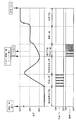
- FIG. 9 is a schematic diagram showing the flow of the bread making course for rice grains in the automatic bread maker of the present embodiment.
- the temperature indicates the temperature of the bread container 50.
- the water absorption process before pulverization one form of liquid absorption process before pulverization
- the pulverization process the water absorption process after pulverization (one form of liquid absorption process after pulverization)
- the kneading step, the fermentation step, and the firing step are sequentially performed in this order.
- the user In executing the rice grain breadmaking course, the user attaches the crushing blade 54 and the cover 70 with the kneading blade 72 to the bread container 50. Then, the user measures a predetermined amount of rice grains and water (for example, 220 g of rice grains and 210 g of water) and puts them in the bread container 50.
- rice grains and water are mixed, but instead of mere water, for example, a liquid having a taste component such as broth, fruit juice, a liquid containing alcohol, or the like may be used.
- the user puts the bread container 50 into which the rice grains and water have been put into the baking chamber 40, closes the lid 30, selects the rice grain breadmaking course by the operation unit 20, and presses the start key. Thereby, the bread-making course for rice grains which manufactures bread from rice grains is started.
- the water absorption step before pulverization is a step aimed at making the rice grains easily pulverized to the core in the subsequent pulverization step by including water (one form of liquid) in the rice grains.
- the control device 81 controls the mixture of rice grains and water to be left in the bread container 50 for a predetermined time (for example, 50 minutes). This predetermined time may be obtained experimentally as a time during which the subsequent pulverization process can be performed efficiently.
- the temperature of the bread container 50 is detected by the second temperature detection unit 19 (temperature detection is performed with the tip of the temperature sensor 19a in contact with the container 50), and the detected temperature
- the time for the water absorption step before pulverization may be changed by the above. Specifically, for example, the relationship between the temperature of the bread container 50 and the optimum water absorption time is examined in advance by experiment (for example, the water absorption time is examined at intervals of 5 ° C. between 5 ° C. and 35 ° C.) This information is stored in the ROM of the control device 81.
- the temperature of the bread container 50 is detected in the stage which put the rice grain and water in the bread container 50, and the water absorption time is determined from the detected temperature and the information stored in the control device 81 in advance. Like that. And what is necessary is just to make it perform the water absorption process before a grinding
- the pulverization blade 54 may be rotated at an initial stage of the water absorption step before pulverization, and the pulverization blade 54 may be intermittently rotated thereafter. If it does in this way, the surface of a rice grain can be damaged, and the liquid absorption efficiency of a rice grain will be improved.
- a pulverization step for pulverizing the rice grains is executed according to a command from the control device 81.
- the pulverization blade 54 is rotated at high speed in a mixture of rice grains and water.
- the control device 81 controls the pulverization motor 64 to rotate the blade rotation shaft 52 in the reverse direction, and starts the rotation of the pulverization blade 54 in the mixture of rice grains and water.
- the cover 70 also starts rotating following the rotation of the blade rotation shaft 52, but the rotation of the cover 70 is immediately prevented by the following operation.
- the rotation direction of the cover accompanying the rotation of the blade rotation shaft 52 for rotating the crushing blade 54 is the clockwise direction in FIG. 5, and the kneading blade 72 has been in the folded position (the position shown in FIG. 5) until then.
- the resistance is changed by the resistance received from the mixture of rice grains and water and the posture is changed to the posture shown in FIG.
- the clutch 76 connects the blade rotation shaft 52 and the cover 70 so that the second engagement body 76b deviates from the rotation track of the first engagement body 76a. Separate.
- the kneading blade 72 in the open position abuts against the inner wall of the bread container 50 as shown in FIG.
- the pulverization of the rice grains in the pulverization step is performed in a state where water is soaked in the rice grains by the water absorption step before pulverization, so that the rice grains can be easily pulverized to the core.
- the rotation of the grinding blade 54 is intermittent. In this intermittent rotation, for example, a cycle of rotating for 1 minute and stopping for 3 minutes is executed five times. In the last cycle, the stop for 3 minutes is not performed.
- the rotation of the pulverizing blade 54 may be continuous rotation, intermittent rotation is preferable because the rice grains can be uniformly crushed by convection by intermittent rotation.
- the crushing process is completed in a predetermined time (17 minutes in this embodiment).
- the grain size of the pulverized powder may vary depending on the hardness of the rice grains and the environmental conditions. For this reason, the end of the pulverization process may be determined using the magnitude of the load (torque) during pulverization as an index.
- the temperature sensor 19a of the second temperature detection unit 19 is in a position where it does not contact the bread container 50. Thereby, damage to temperature sensor 19a and bread container 50 can be prevented.
- the temperature of the bread container 50 increases due to friction during the pulverization.
- the temperature of the bread container 50 is about 40 to 45 ° C., for example.
- the automatic bread maker 1 is provided with a water absorption step after pulverization in which the pulverized rice grains are left in a state immersed in water after the pulverization step.
- This water absorption step after pulverization is a cooling period for lowering the temperature of the pulverized powder of rice grains, and at the same time, is a step of increasing the amount of fine particles by further absorbing water into the pulverized powder.
- the water absorption step after pulverization may be configured to be performed only for a predetermined time. In such a configuration, for example, due to the influence of environmental temperature, the bread container 50 (bread at the start of the next kneading step) is performed. In some cases, the temperature of the raw material) varies and a good bread cannot be obtained.
- the first temperature detection unit 18 detects the outside air temperature
- the second temperature detection unit 19 the tip of the temperature sensor 19a is not brought into contact with the bread container 50. That is, bread
- the ambient temperature is detected at the end of the pulverization process (may be before the start of the pulverization process) by using the temperature around the container 50 (the temperature in the baking chamber 40), and pulverization is performed based on this environmental temperature. You may make it determine the time of a post-water absorption process. Thereby, the dispersion
- the relationship between the environmental temperature and the time during which the temperature of the bread container 50 after the pulverization process becomes the optimum temperature is examined beforehand. It is stored in the ROM of the control device 81. For example, at an environmental temperature of 5 ° C. to 35 ° C., the optimum water absorption time is examined and stored at intervals of 5 ° C. Then, as described above, the environmental temperature is detected, the water absorption time is determined from the detected temperature and the information stored in the control device 81 in advance, and the water absorption process after pulverization is executed for the determined time. What should I do?
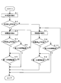
- the water absorption step after pulverization is executed not by the above flow but by another flow as shown in FIG.
- the control device 81 detects the outside air temperature by the first temperature detector 18 (step S1). It is confirmed whether or not the detected outside air temperature is equal to or lower than a predetermined temperature set in advance (step S2).
- the predetermined temperature is a preferable temperature when starting the kneading process, and is set to a temperature of 28 ° C. or higher and 30 ° C. or lower, for example.
- Step S3 the control device 81 detects the temperature of the bread container 50 by the second temperature detector 19 (Step S3).
- temperature detection is performed with the tip of the temperature sensor 19 a of the second temperature detection unit 19 in contact with the bread container 50.
- the control apparatus 81 confirms whether the temperature of the detected bread container 50 is below predetermined temperature (step S4).
- the control device 81 sets a first time (for example, 30) set in advance after the water absorption process after crushing is started. It is confirmed whether or not (minute) has elapsed (step S5).
- the first time is provided so that the time for the water absorption step after pulverization does not become too short. That is, as described above, the water absorption step after pulverization also plays a role of increasing the amount of fine particles of the pulverized powder by further absorbing water into the pulverized powder obtained in the pulverization step. For this reason, since it is not preferable if the water absorption process after grinding becomes too short, the first time is set.
- step S5 for confirming whether or not the first time has elapsed may be configured not to be provided.
- step S5 When the first time has elapsed since the start of the water absorption process after pulverization (Yes in step S5), the control device 81 ends the water absorption process after pulverization. On the other hand, if the first time has not elapsed since the start of the water absorption process after pulverization (No in step S5), the control device 81 waits until the first time elapses, and performs the water absorption process after pulverization. finish.
- the control device 81 When the detected temperature of the bread container 50 is higher than the predetermined temperature (No in step S4), the control device 81 performs a second time (first time) set in advance after the water absorption process after crushing is started. It is confirmed whether or not the time is longer than the time, for example, 60 minutes (step S6). And when the 2nd time has passed (it is Yes at Step S6), even if the temperature of bread container 50 has not reached predetermined temperature, the water absorption process after crushing is ended. On the other hand, when the second time has not elapsed (No in step S6), the process returns to step S3, and the operations after step S3 are performed.
- Step S6 for confirming whether or not the second time has elapsed from the start of the water absorption step after pulverization is provided for the following reason. That is, it may be assumed that it takes a very long time for the temperature of the bread container 50 to drop to a predetermined temperature. In such a case, if the kneading process is not started indefinitely, the bread production time becomes extremely long, and the user may feel inconvenient. For this reason, the second time is set as the upper limit of the water absorption time so that the time of the water absorption step after crushing does not become too long. However, this step S6 may be omitted. In this case, it waits until the temperature of the bread container 50 reaches a predetermined temperature, and the water absorption process after pulverization is completed.
- the water absorption step after pulverization is terminated when the temperature falls to the outside temperature. In detail, it processes as follows.
- Step S2 when the outside air temperature is higher than the predetermined temperature in Step S2 (No in Step S2), the control device 81 detects the temperature of the bread container 50 by the second temperature detection unit 19 (Step S7). Then, the control device 81 confirms whether or not the detected temperature of the bread container 50 is equal to or lower than the outside air temperature (step S8).
- step S8 determines whether or not the first time has elapsed since the water absorption process after pulverization was started. Confirm (step S9).
- the first time is determined for the same purpose as in step S5. And like step 5, it is good also as a structure which does not provide step S9.
- step S9 If the first time has elapsed since the start of the water absorption process after pulverization (Yes in step S9), the control device 81 ends the water absorption process after pulverization. On the other hand, if the first time has not elapsed since the start of the water absorption process after pulverization (No in step S9), the control device 81 waits until the first time elapses and performs the water absorption process after pulverization. finish.
- step S8 If the detected temperature of the bread container 50 is higher than the outside air temperature (No in step S8), the controller 81 has a second time set in advance since the water absorption step after crushing has started. It is confirmed whether or not (step S10). And when the 2nd time has passed (it is Yes at Step S10), even if the temperature of bread container 50 has not reached outside temperature, the water absorption process after crushing is ended. On the other hand, when the second time has not elapsed (No in step S10), the process returns to step S7, and the operations after step S7 are performed.
- step S10 is the same as the purpose of providing step S6.
- Step S10 may be configured not to be provided similarly to step S6. In this case, the process waits until the temperature of the bread container 50 reaches the outside air temperature, and the water absorption process after pulverization is completed.
- the kneading process is subsequently performed.
- seasonings such as gluten, salt, sugar, and shortening are each put in a predetermined amount (for example, gluten 50 g, sugar 16 g, salt 4 g, shortening 10 g) into the bread container 50.
- This insertion may be performed, for example, by the user's hand, or may be performed without bothering the user by providing an automatic insertion device.
- gluten is not essential as a bread ingredient. For this reason, you may judge whether to add to a bread raw material according to liking. Further, a thickening stabilizer (for example, guar gum) may be added instead of gluten.
- a thickening stabilizer for example, guar gum
- the control device 81 controls the kneading motor 60 to rotate the blade rotation shaft 52 in the forward direction.
- the cover 70 rotates in the forward direction (counterclockwise in FIG. 6) following the forward rotation of the blade rotation shaft 52, the kneading blade 72 is opened by receiving resistance from the bread ingredients in the bread container 50. From (see FIG. 6) to the folded posture (see FIG. 5). In response to this, as shown in FIG.
- the clutch 76 connects the blade rotating shaft 52 and the cover 70 at an angle at which the second engagement body 76 b interferes with the rotation track of the first engagement body 76 a.
- the cover 70 and the kneading blade 72 rotate in the forward direction together with the blade rotation shaft 52.
- the kneading blade 72 is rotated at a low speed and a high torque.
- Bread ingredients are kneaded by the rotation of the kneading blade 72 and kneaded into a dough that has a predetermined elasticity.
- an element of “kneading” is added to the kneading.
- the rotation of the kneading blade 72 in the kneading process may be continuous rotation from beginning to end, in the automatic bread maker 1, the initial stage of the kneading process is intermittent rotation, and the latter half is continuous rotation.
- yeast for example, dry yeast
- This yeast may be input by the user or may be automatically input.
- the reason why yeast is not added together with gluten or the like is to avoid direct contact between the yeast (dry yeast) and water as much as possible. However, in some cases, yeast and gluten may be added simultaneously.
- a predetermined time for example, 15 minutes
- the time of the kneading process is constant, the degree of bread dough may vary depending on the environmental temperature. For this reason, it is good also as a structure which detects the outside temperature (temperature in the baking chamber 40 depending on the case) at the time of the start of a kneading process, and changes the time which a kneading process requires by outside temperature.
- the timing for ending the kneading process may be determined using the magnitude of the load (torque) during kneading as an index.
- the control device 81 controls the sheath heater 41 to adjust the temperature of the baking chamber 40 to a predetermined temperature (for example, 32 ° C.).
- a predetermined temperature for example, 32 ° C.
- the tip of the temperature sensor 19 a of the second temperature detection unit 19 is in a position where it does not contact the bread container 50.
- the temperature sensor 19a and the bread container 50 are hardly damaged.
- ingredients may be introduced during the kneading process.
- the fermentation process is subsequently executed according to a command from the control device 81.
- the control device 81 controls the sheathed heater 41 to set the temperature of the baking chamber 40 to a temperature at which fermentation proceeds (for example, 38 ° C.).
- the bread dough is left for a predetermined time (in this embodiment, 50 minutes) in an environment in which fermentation proceeds.
- degassing or rounding of the dough may be performed during the fermentation process.
- the time of a fermentation process is made constant, the swelling degree etc. of bread dough may change with external temperature. For this reason, it is good also as a structure which detects outside temperature at the time of the start of a fermentation process, and changes the time which a fermentation process requires with outside temperature.
- the outside air temperature is high, it is preferable to make the fermentation process short, and when the outside air temperature is low, it is preferable to make the fermentation process long.
- the firing process is subsequently performed according to a command from the control device 81.
- the control device 81 controls the sheathed heater 41 to raise the temperature of the baking chamber 40 to a temperature suitable for baking (for example, 125 ° C.), and for a predetermined time (50 in this embodiment) in the baking environment. Min) Bake bread.
- the end of the firing process is notified to the user by, for example, a display on a liquid crystal display panel (not shown) of the operation unit 20 or a notification sound.
- the user opens the lid 30 and takes out the bread container 50.
- the automatic bread maker 1 of the present embodiment it is possible to bake bread from rice grains, which is very convenient. And since it was set as the structure which provides the water absorption process after a grinding
- the automatic bread maker shown above is an example of the present invention, and the configuration of the automatic bread maker to which the present invention is applied is not limited to the embodiment described above.
- bread is produced from rice grains.
- the bread is not limited to rice grains, and bread is produced using grains such as wheat, barley, straw, buckwheat, buckwheat, corn, and soybeans as raw materials. Even in this case, the present invention is applied.
- the portion configured to detect the temperature of the bread container 50 may be changed to a structure that detects the temperature of the bread raw material put into the bread container 50. Moreover, you may change into the structure which detects the ambient temperature (temperature in the baking chamber 40) of the bread container 50 depending on the case also as the part made into the structure which detects external temperature.
- the time required for the water absorption process after pulverization is determined while appropriately detecting the temperature of the bread container 50 during the water absorption process after pulverization.
- the outside air temperature and the temperature of the bread container 50 are detected, and the temperature decrease rate of the bread container 50 predicted by the outside air temperature (need to be obtained by experiments in advance).
- the temperature of the bread container 50 and the time required for the water absorption step after pulverization may be determined.
- the manufacturing process executed in the above-described rice grain breadmaking course is an example, and may be another manufacturing process.
- the water absorption step before pulverization is performed before the pulverization step, but the water absorption step before pulverization may not be performed. Good.
- the automatic bread maker 1 is configured to include two blades of the crushing blade 54 and the kneading blade 72.
- the present invention is not limited to this, and the automatic bread maker may be configured to include only one blade for both crushing and kneading.
- the present invention is suitable for an automatic bread maker for home use.
Landscapes
- Life Sciences & Earth Sciences (AREA)
- Engineering & Computer Science (AREA)
- Food Science & Technology (AREA)
- Baking, Grill, Roasting (AREA)
- Food-Manufacturing Devices (AREA)
- Manufacturing And Processing Devices For Dough (AREA)
Abstract
Description
10 本体
18 第1温度検知部
19 第2温度検知部
50 パン容器
81 制御装置(制御部)
Claims (7)
- パン原料が投入される容器と、
前記容器を受け入れる本体と、
前記容器が前記本体に受け入れられた状態で、パンの製造工程を実行させる制御部と、
を備える自動製パン器であって、
前記パンの製造工程には、前記容器内で穀物粒を粉砕する粉砕工程と、前記粉砕工程によって粉砕された穀物粒の粉砕粉に吸液させる粉砕後吸液工程と、が含まれる、自動製パン器。 - 外気温度、前記容器の温度、前記容器周辺の温度、及び前記容器内のパン原料温度のうちの少なくとも1つを検知可能な温度検知部を更に備え、
前記制御部は、前記温度検知部で検知された温度に基づいて、前記粉砕後吸液工程の時間を制御する、請求項1に記載の自動製パン器。 - 前記温度検知部は、前記容器の温度を検知可能に設けられ、
前記制御部は、前記粉砕後吸液工程において、前記容器の温度が所定の温度に到達すると、前記粉砕後吸液工程を終了させる、請求項2に記載の自動製パン器。 - 前記温度検知部は、前記容器の温度に加えて前記外気温度を検知可能に設けられ、
前記制御部は、前記粉砕後吸液工程において、前記外気温度が前記所定の温度よりも高い場合には、前記容器の温度が前記外気温度に到達すると、前記粉砕後吸液工程を終了させる、請求項3に記載の自動製パン器。 - 前記制御部は、
前記粉砕後吸液工程の時間が、第1の時間以上、第2の時間以内となるように前記粉砕後吸液工程を制御し、
前記温度検知部からの情報により前記粉砕後吸液工程が終了できると判断される場合であっても、前記第1の時間に満たない場合には前記粉砕後吸液工程を終了させず、
前記温度検知部からの情報により前記粉砕後吸液工程が終了できないと判断される場合であっても、前記第2の時間を超える場合には前記粉砕後吸液工程を終了させる、請求項3又は4に記載の自動製パン器。 - 外気温度、前記容器の温度、前記容器周辺の温度、及び前記容器内のパン原料温度のうちの少なくとも1つを検知可能な温度検知部を更に備え、
前記制御部は、温度に対応して吸液時間を定めた吸液時間テーブルと、前記温度検知部を用いて前記穀物粒の粉砕前、或いは、前記穀物粒の粉砕後に検知された温度とに基づいて、前記粉砕後吸液工程における吸液時間を決定する、請求項1に記載の自動製パン器。 - 前記パンの製造工程においては、前記容器内の穀物粒に液体を吸液させる粉砕前吸液工程と、前記粉砕工程と、前記粉砕後吸液工程と、穀物粒の粉砕粉を含む前記容器内のパン原料をパン生地に練り上げる練り工程と、練り上げられたパン生地を発酵させる発酵工程と、発酵させたパン生地を焼成する焼成工程と、が順次に連続して行われる、請求項1に記載の自動製パン器。
Priority Applications (2)
| Application Number | Priority Date | Filing Date | Title |
|---|---|---|---|
| CN2010800524308A CN102665508A (zh) | 2009-11-27 | 2010-11-18 | 自动制面包机 |
| US13/512,298 US20120266757A1 (en) | 2009-11-27 | 2010-11-18 | Automatic bread maker |
Applications Claiming Priority (2)
| Application Number | Priority Date | Filing Date | Title |
|---|---|---|---|
| JP2009270384A JP2011110274A (ja) | 2009-11-27 | 2009-11-27 | 自動製パン器 |
| JP2009-270384 | 2009-11-27 |
Publications (1)
| Publication Number | Publication Date |
|---|---|
| WO2011065273A1 true WO2011065273A1 (ja) | 2011-06-03 |
Family
ID=44066377
Family Applications (1)
| Application Number | Title | Priority Date | Filing Date |
|---|---|---|---|
| PCT/JP2010/070541 Ceased WO2011065273A1 (ja) | 2009-11-27 | 2010-11-18 | 自動製パン器 |
Country Status (5)
| Country | Link |
|---|---|
| US (1) | US20120266757A1 (ja) |
| JP (1) | JP2011110274A (ja) |
| CN (1) | CN102665508A (ja) |
| TW (1) | TW201138693A (ja) |
| WO (1) | WO2011065273A1 (ja) |
Cited By (1)
| Publication number | Priority date | Publication date | Assignee | Title |
|---|---|---|---|---|
| CN105193300A (zh) * | 2015-09-17 | 2015-12-30 | 广东辉胜达电器股份有限公司 | 一种自动胶囊面包机及其面包制作方法 |
Families Citing this family (3)
| Publication number | Priority date | Publication date | Assignee | Title |
|---|---|---|---|---|
| JP6082976B2 (ja) * | 2012-09-14 | 2017-02-22 | パナソニックIpマネジメント株式会社 | 自動製パン器 |
| CN103654457B (zh) * | 2012-09-19 | 2017-06-20 | 漳州灿坤实业有限公司 | 一种面包自动制作机、面包原料盒和面包的快捷制作方法 |
| USD1129177S1 (en) * | 2023-12-27 | 2026-06-09 | Jiangmen Kangbaishi Electrical Appliances Co., Ltd | Bread maker |
Citations (4)
| Publication number | Priority date | Publication date | Assignee | Title |
|---|---|---|---|---|
| JPH09507385A (ja) * | 1993-10-22 | 1997-07-29 | ザ アンダーソンズ | パンの製造機及び製造方法 |
| JP2003135012A (ja) * | 2001-10-31 | 2003-05-13 | Kyoto Eiyo Kagaku Kenkyusho:Kk | 穀類胚芽加工品の製造方法およびその穀類胚芽加工品を含む食品 |
| JP2008307328A (ja) * | 2007-06-18 | 2008-12-25 | Mitsubishi Electric Corp | 加熱調理器 |
| JP2009050485A (ja) * | 2007-08-28 | 2009-03-12 | Panasonic Corp | 炊飯器 |
Family Cites Families (3)
| Publication number | Priority date | Publication date | Assignee | Title |
|---|---|---|---|---|
| CN1094745C (zh) * | 1994-11-14 | 2002-11-27 | 松下电器产业株式会社 | 自动面包机 |
| WO2004047561A1 (ja) * | 2002-11-25 | 2004-06-10 | Kabushiki Kaisha Hayashibara Seibutsu Kagaku Kenkyujo | 米粉の製造方法とその用途 |
| JP3851623B2 (ja) * | 2003-02-07 | 2006-11-29 | 株式会社新潟グルメ | 自動製パン器 |
-
2009
- 2009-11-27 JP JP2009270384A patent/JP2011110274A/ja active Pending
-
2010
- 2010-11-18 CN CN2010800524308A patent/CN102665508A/zh active Pending
- 2010-11-18 WO PCT/JP2010/070541 patent/WO2011065273A1/ja not_active Ceased
- 2010-11-18 US US13/512,298 patent/US20120266757A1/en not_active Abandoned
- 2010-11-24 TW TW099140507A patent/TW201138693A/zh unknown
Patent Citations (4)
| Publication number | Priority date | Publication date | Assignee | Title |
|---|---|---|---|---|
| JPH09507385A (ja) * | 1993-10-22 | 1997-07-29 | ザ アンダーソンズ | パンの製造機及び製造方法 |
| JP2003135012A (ja) * | 2001-10-31 | 2003-05-13 | Kyoto Eiyo Kagaku Kenkyusho:Kk | 穀類胚芽加工品の製造方法およびその穀類胚芽加工品を含む食品 |
| JP2008307328A (ja) * | 2007-06-18 | 2008-12-25 | Mitsubishi Electric Corp | 加熱調理器 |
| JP2009050485A (ja) * | 2007-08-28 | 2009-03-12 | Panasonic Corp | 炊飯器 |
Cited By (2)
| Publication number | Priority date | Publication date | Assignee | Title |
|---|---|---|---|---|
| CN105193300A (zh) * | 2015-09-17 | 2015-12-30 | 广东辉胜达电器股份有限公司 | 一种自动胶囊面包机及其面包制作方法 |
| CN105193300B (zh) * | 2015-09-17 | 2019-03-12 | 漳州灿坤实业有限公司 | 一种自动胶囊面包机及其面包制作方法 |
Also Published As
| Publication number | Publication date |
|---|---|
| JP2011110274A (ja) | 2011-06-09 |
| CN102665508A (zh) | 2012-09-12 |
| US20120266757A1 (en) | 2012-10-25 |
| TW201138693A (en) | 2011-11-16 |
Similar Documents
| Publication | Publication Date | Title |
|---|---|---|
| JP5418212B2 (ja) | 自動製パン器 | |
| JP5449795B2 (ja) | 自動製パン機 | |
| KR20110084105A (ko) | 자동제빵기 | |
| JP2011161029A (ja) | 自動製パン器 | |
| JP5347833B2 (ja) | 自動製パン器 | |
| TW200416011A (en) | Automatic rice bread maker and rice bread making method | |
| JP2011110274A (ja) | 自動製パン器 | |
| JP5289245B2 (ja) | 自動製パン機 | |
| JP5295039B2 (ja) | 自動製パン機 | |
| JP2011143075A (ja) | 自動製パン器 | |
| JP2011224165A (ja) | 自動製パン器 | |
| WO2011074427A1 (ja) | 自動製パン器 | |
| JP2010246589A (ja) | 自動製パン機 | |
| JP4859965B2 (ja) | 自動製パン機 | |
| JP5402577B2 (ja) | 自動製パン器 | |
| JP2014151032A (ja) | 自動製パン機 | |
| JP4799693B2 (ja) | 自動製パン器 | |
| JP2010184081A (ja) | 自動製パン機 | |
| JP4799694B2 (ja) | 自動製パン器 | |
| JP5957738B2 (ja) | 自動製パン機 | |
| JP2013106894A (ja) | 自動製パン器 | |
| WO2011065272A1 (ja) | 自動製パン器 | |
| JP5682695B2 (ja) | 自動製パン機 | |
| JP4794675B2 (ja) | 自動製パン器 | |
| JP4799692B2 (ja) | 自動製パン器 |
Legal Events
| Date | Code | Title | Description |
|---|---|---|---|
| WWE | Wipo information: entry into national phase |
Ref document number: 201080052430.8 Country of ref document: CN |
|
| 121 | Ep: the epo has been informed by wipo that ep was designated in this application |
Ref document number: 10833119 Country of ref document: EP Kind code of ref document: A1 |
|
| WWE | Wipo information: entry into national phase |
Ref document number: 13512298 Country of ref document: US |
|
| NENP | Non-entry into the national phase |
Ref country code: DE |
|
| 122 | Ep: pct application non-entry in european phase |
Ref document number: 10833119 Country of ref document: EP Kind code of ref document: A1 |