WO2011064862A1 - 固体電池モジュール - Google Patents
固体電池モジュール Download PDFInfo
- Publication number
- WO2011064862A1 WO2011064862A1 PCT/JP2009/069941 JP2009069941W WO2011064862A1 WO 2011064862 A1 WO2011064862 A1 WO 2011064862A1 JP 2009069941 W JP2009069941 W JP 2009069941W WO 2011064862 A1 WO2011064862 A1 WO 2011064862A1
- Authority
- WO
- WIPO (PCT)
- Prior art keywords
- negative electrode
- positive electrode
- battery
- electrode layer
- solid electrolyte
- Prior art date
- Legal status (The legal status is an assumption and is not a legal conclusion. Google has not performed a legal analysis and makes no representation as to the accuracy of the status listed.)
- Ceased
Links
Images


Classifications
-
- H—ELECTRICITY
- H01—ELECTRIC ELEMENTS
- H01M—PROCESSES OR MEANS, e.g. BATTERIES, FOR THE DIRECT CONVERSION OF CHEMICAL ENERGY INTO ELECTRICAL ENERGY
- H01M10/00—Secondary cells; Manufacture thereof
- H01M10/04—Construction or manufacture in general
- H01M10/0413—Large-sized flat cells or batteries for motive or stationary systems with plate-like electrodes
-
- H—ELECTRICITY
- H01—ELECTRIC ELEMENTS
- H01M—PROCESSES OR MEANS, e.g. BATTERIES, FOR THE DIRECT CONVERSION OF CHEMICAL ENERGY INTO ELECTRICAL ENERGY
- H01M10/00—Secondary cells; Manufacture thereof
- H01M10/04—Construction or manufacture in general
- H01M10/0436—Small-sized flat cells or batteries for portable equipment
-
- H—ELECTRICITY
- H01—ELECTRIC ELEMENTS
- H01M—PROCESSES OR MEANS, e.g. BATTERIES, FOR THE DIRECT CONVERSION OF CHEMICAL ENERGY INTO ELECTRICAL ENERGY
- H01M10/00—Secondary cells; Manufacture thereof
- H01M10/04—Construction or manufacture in general
- H01M10/0463—Cells or batteries with horizontal or inclined electrodes
-
- H—ELECTRICITY
- H01—ELECTRIC ELEMENTS
- H01M—PROCESSES OR MEANS, e.g. BATTERIES, FOR THE DIRECT CONVERSION OF CHEMICAL ENERGY INTO ELECTRICAL ENERGY
- H01M50/00—Constructional details or processes of manufacture of the non-active parts of electrochemical cells other than fuel cells, e.g. hybrid cells
- H01M50/50—Current conducting connections for cells or batteries
- H01M50/528—Fixed electrical connections, i.e. not intended for disconnection
-
- H—ELECTRICITY
- H01—ELECTRIC ELEMENTS
- H01M—PROCESSES OR MEANS, e.g. BATTERIES, FOR THE DIRECT CONVERSION OF CHEMICAL ENERGY INTO ELECTRICAL ENERGY
- H01M50/00—Constructional details or processes of manufacture of the non-active parts of electrochemical cells other than fuel cells, e.g. hybrid cells
- H01M50/50—Current conducting connections for cells or batteries
- H01M50/531—Electrode connections inside a battery casing
- H01M50/533—Electrode connections inside a battery casing characterised by the shape of the leads or tabs
-
- H—ELECTRICITY
- H01—ELECTRIC ELEMENTS
- H01M—PROCESSES OR MEANS, e.g. BATTERIES, FOR THE DIRECT CONVERSION OF CHEMICAL ENERGY INTO ELECTRICAL ENERGY
- H01M50/00—Constructional details or processes of manufacture of the non-active parts of electrochemical cells other than fuel cells, e.g. hybrid cells
- H01M50/50—Current conducting connections for cells or batteries
- H01M50/531—Electrode connections inside a battery casing
- H01M50/54—Connection of several leads or tabs of plate-like electrode stacks, e.g. electrode pole straps or bridges
-
- H—ELECTRICITY
- H01—ELECTRIC ELEMENTS
- H01M—PROCESSES OR MEANS, e.g. BATTERIES, FOR THE DIRECT CONVERSION OF CHEMICAL ENERGY INTO ELECTRICAL ENERGY
- H01M10/00—Secondary cells; Manufacture thereof
- H01M10/05—Accumulators with non-aqueous electrolyte
- H01M10/052—Li-accumulators
- H01M10/0525—Rocking-chair batteries, i.e. batteries with lithium insertion or intercalation in both electrodes; Lithium-ion batteries
-
- H—ELECTRICITY
- H01—ELECTRIC ELEMENTS
- H01M—PROCESSES OR MEANS, e.g. BATTERIES, FOR THE DIRECT CONVERSION OF CHEMICAL ENERGY INTO ELECTRICAL ENERGY
- H01M10/00—Secondary cells; Manufacture thereof
- H01M10/05—Accumulators with non-aqueous electrolyte
- H01M10/058—Construction or manufacture
- H01M10/0585—Construction or manufacture of accumulators having only flat construction elements, i.e. flat positive electrodes, flat negative electrodes and flat separators
-
- H—ELECTRICITY
- H01—ELECTRIC ELEMENTS
- H01M—PROCESSES OR MEANS, e.g. BATTERIES, FOR THE DIRECT CONVERSION OF CHEMICAL ENERGY INTO ELECTRICAL ENERGY
- H01M6/00—Primary cells; Manufacture thereof
- H01M6/42—Grouping of primary cells into batteries
-
- Y—GENERAL TAGGING OF NEW TECHNOLOGICAL DEVELOPMENTS; GENERAL TAGGING OF CROSS-SECTIONAL TECHNOLOGIES SPANNING OVER SEVERAL SECTIONS OF THE IPC; TECHNICAL SUBJECTS COVERED BY FORMER USPC CROSS-REFERENCE ART COLLECTIONS [XRACs] AND DIGESTS
- Y02—TECHNOLOGIES OR APPLICATIONS FOR MITIGATION OR ADAPTATION AGAINST CLIMATE CHANGE
- Y02E—REDUCTION OF GREENHOUSE GAS [GHG] EMISSIONS, RELATED TO ENERGY GENERATION, TRANSMISSION OR DISTRIBUTION
- Y02E60/00—Enabling technologies; Technologies with a potential or indirect contribution to GHG emissions mitigation
- Y02E60/10—Energy storage using batteries
-
- Y—GENERAL TAGGING OF NEW TECHNOLOGICAL DEVELOPMENTS; GENERAL TAGGING OF CROSS-SECTIONAL TECHNOLOGIES SPANNING OVER SEVERAL SECTIONS OF THE IPC; TECHNICAL SUBJECTS COVERED BY FORMER USPC CROSS-REFERENCE ART COLLECTIONS [XRACs] AND DIGESTS
- Y02—TECHNOLOGIES OR APPLICATIONS FOR MITIGATION OR ADAPTATION AGAINST CLIMATE CHANGE
- Y02P—CLIMATE CHANGE MITIGATION TECHNOLOGIES IN THE PRODUCTION OR PROCESSING OF GOODS
- Y02P70/00—Climate change mitigation technologies in the production process for final industrial or consumer products
- Y02P70/50—Manufacturing or production processes characterised by the final manufactured product
Definitions
- the present invention relates to a solid battery module.
- Lithium ion secondary batteries are characterized by higher energy density than other secondary batteries and capable of operating at high voltages. For this reason, it is used as a secondary battery that can be easily reduced in size and weight in information equipment such as a mobile phone, and in recent years, there is an increasing demand for large motive power such as for electric vehicles and hybrid vehicles.
- the lithium ion secondary battery includes a positive electrode layer and a negative electrode layer, and an electrolyte disposed therebetween, and the electrolyte is composed of a non-aqueous liquid or solid.
- electrolytic solution a non-aqueous liquid
- the electrolytic solution penetrates into the positive electrode layer. Therefore, the interface between the positive electrode active material constituting the positive electrode layer and the electrolyte is easily formed, and the performance is easily improved.
- the widely used electrolyte is flammable, it is necessary to mount a system for ensuring safety.
- the solid electrolyte is nonflammable, the above system can be simplified.
- solid battery a lithium ion secondary battery having a layer containing a non-combustible solid electrolyte (hereinafter, sometimes referred to as “solid electrolyte layer”).
- solid electrolyte layer a layer containing a non-combustible solid electrolyte
- Patent Document 1 discloses a grid-like solid state power generation cell including a power generation element in which a positive electrode active material, a solid electrolyte, and a negative electrode active material are layered on a bendable sheet. There is disclosed a sheet-like battery characterized in that a plurality of battery cells are arranged in the above.
- Patent Document 2 discloses a planar lithium unit cell that is housed in a unit cell package, in which positive and negative electrode current collectors are sealed and taken out of the unit cell package, and a plurality of lithium units.
- a lithium secondary battery including an outer package for stacking and storing unit cells is disclosed.
- a rod-shaped material is passed through a hole provided in a positive electrode current collector and a negative electrode current collector of a lithium unit cell, and a plurality of lithium cell cells passed through the rod-shaped material are pressed with a fixing material and a pressing material. After being fixed in this manner, a form of storing in an outer package is disclosed.
- a plurality of solid-state power generation cells each including a battery element in which a positive electrode active material, a solid electrolyte, and a negative electrode active material are layered on a bendable sheet are arranged in a grid pattern.
- This arrangement prevents (or mitigates) mechanical stress in the power generation cell and provides high reliability to the sheet battery, and relatively uniform flexibility in the sheet battery even if the power generation cell is rigid. It is considered that the reliability can be improved by imparting the property and preventing the shape change of the power generation cell.
- the technique disclosed in Patent Document 1 has a problem that it is difficult to determine the positions where the solid power generation cells are arranged and arrange them in an orderly manner.
- Patent Document 2 since a plurality of lithium unit cells are stacked by passing a rod-shaped material through a hole provided in the lithium unit cell, the displacement of the lithium unit cell is suppressed. Will be possible. However, in the technique disclosed in Patent Document 2, it is possible to stack a plurality of lithium unit cells in one outer package, but it is not possible to arrange lithium unit cells in a direction crossing the stacking direction. There wasn't.
- the present invention provides a solid battery module in which a plurality of battery elements are arranged in a direction intersecting with the stacking direction of members constituting the battery elements, and the installation position of the battery elements can be easily determined. This is the issue.
- the present invention includes a plurality of battery elements each including a solid electrolyte layer and a pair of positive electrode layers and negative electrode layers that sandwich the solid electrolyte layer, and the plurality of battery elements include a solid electrolyte layer, a positive electrode layer, and a negative electrode layer.
- a solid battery module is provided that is arranged side by side in a direction intersecting the stacking direction, and includes a substrate on which the plurality of battery elements are disposed, and the substrate includes a positioning portion that determines an installation position of the plurality of battery elements.
- the “battery element” is configured such that at least one of a solid electrolyte layer, a positive electrode layer, and a negative electrode layer is laminated, and a current collector or the like is provided so that charging / discharging is possible.
- the positioning portion In the solid battery module of the present invention, it is preferable that adjacent battery elements share the positioning portion. By setting it as this form, it can position with few positioning parts and can raise the energy density of a battery module.
- the positioning portion is a rod-like body erected from the substrate, and the battery element protrudes in a direction intersecting with the stacking direction of the solid electrolyte layer, the positive electrode layer, and the negative electrode layer.
- a hole or notch corresponding to the rod-shaped body is provided in the projecting portion, and the projecting portion provided in the adjacent battery element is overlapped with the rod-shaped body in the hole or notch. Is preferably inserted.
- a solid battery module in which a plurality of battery elements are arranged in a direction intersecting with the stacking direction of members constituting the battery elements, and the installation position of the battery elements can be easily determined. can do.
- FIG. 3 is a diagram schematically showing a cross section in a direction orthogonal to the cross section shown in FIG. 2 for the solid state battery shown in FIG. 1. It is the schematic for demonstrating the structure of the battery element with which the solid battery module of this invention is equipped.
- the present invention will be described in detail with reference to a lithium secondary battery.
- the present invention is not limited to the embodiment and can be applied to various solid batteries.
- FIG. 1 is a diagram schematically showing a plan view of a solid battery 1 including a solid battery module 10 of the present invention.
- FIG. 2 is a schematic view for explaining the configuration of the solid battery module 10 of the present invention, and schematically shows a cross section of the solid battery 1 shown in FIG. In FIG. 2, some symbols are omitted in order to prevent the drawing from becoming complicated.
- FIG. 3 is a schematic view for explaining the configuration of the solid battery module 10 of the present invention, and is a view of the solid battery 1 shown in FIG. In FIG. 3, a part of the exterior body 120 is omitted for easy understanding of the configuration of the solid battery module 10.
- the solid battery 1 has an exterior body 120, and the solid battery module 10 is accommodated in the exterior body 120.
- a positive terminal 140 and a negative terminal 150 connected to the solid battery module 10 protrude from both ends (left and right direction on the paper surface) of the exterior body 120, and electric energy is externally provided by the positive terminal 140 and the negative terminal 150. Can be taken out.
- the material, size, and the like of the positive electrode terminal 140 and the negative electrode terminal 150 are not particularly limited as long as the electric energy generated in the solid battery module 10 can be taken out to the outside.
- the configuration of the solid battery module 10 will be described in detail with reference to FIGS.
- the solid battery module 10 includes a first battery element 100a, a second battery element 100b, and a third battery element 100c (hereinafter referred to as a first battery element 100c) disposed on a substrate 120a.
- the battery element 100a may be simply referred to as “battery element 100”.
- These battery elements 100a, 100b, and 100c are arranged side by side in a direction that intersects the direction in which members constituting the battery element 100 (a solid electrolyte layer, a positive electrode layer, and a negative electrode layer, which will be described in detail below) are stacked.
- the substrate 120 a is configured by one surface of the exterior body 120, but the present invention is not limited to such a form, and the substrate 120 a is provided separately from the exterior body 120. It may be provided.
- the adjacent battery element 100a and the battery element 100b are electrically connected at the joint 130, and the adjacent battery element 100b and the battery element 100c are also electrically connected at the joint 130. Furthermore, the installation positions of the battery elements 100a, 100b, and 100c are determined by the positioning portions 200 and 200 that are erected from the substrate 120a. The configurations of the joint portions 130 and 130 and the positioning portions 200 and 200 will be described in detail later.
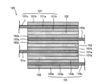
- FIG. 4 is a schematic diagram for explaining the configuration of the battery element 100, and schematically shows a part of the cross section of the battery element 100.
- the battery element 100 has two positive plates 101, three solid electrolyte layers 102, and two negative plates 103.
- the number of the positive electrode plate 101, the solid electrolyte layer 102, and the negative electrode plate 103 is not limited to a specific number, and a suitable number can be appropriately selected as necessary.
- the positive electrode plate 101 includes a positive electrode current collector 101a and positive electrode layers 101b and 101b formed on both surfaces of the positive electrode current collector 101a.
- the positive electrode side current collector 101 a has one direction from the region where the positive electrode plate 101, the solid electrolyte layer 102, and the negative electrode plate 103 actually overlap (a member constituting the battery element 100 is laminated). It is comprised in the form which has the protrusion part which protruded in the direction which cross
- Positive electrode layers 101b and 101b are formed in the positive electrode side current collector 101a at least in a region where the positive electrode plate 101, the solid electrolyte layer 102, and the negative electrode plate 103 overlap.
- the protruding portion protruding from the region where the positive electrode plate 101, the solid electrolyte layer 102, and the negative electrode plate 103 of the positive electrode side current collector 101a overlap each other is not formed with the positive electrode layers 101b and 101b. It is left as a non-formation region 101c.
- This positive electrode plate positive electrode layer non-formation region 101c is provided for connection with the positive electrode terminal 140 in the first battery element 100a, and in the joint part 130 in the second battery element 100b, the first battery element 100a described later is provided.
- the third battery element 100c is used for connection to the negative electrode plate negative electrode layer non-formation region 103c, and the third battery element 100c is used for connection to the negative electrode plate negative electrode layer non-formation region 103c of the second battery element 100b described later. Is done.
- the negative electrode plate 103 includes a negative electrode side current collector 103a and negative electrode layers 103b and 103b formed on both surfaces of the negative electrode side current collector 103a.
- the negative electrode side current collector 103a is formed by laminating the positive electrode plate 101, the solid electrolyte layer 102, and the negative electrode plate 103 in one direction (members constituting the battery element 100 are laminated). It is comprised in the form which has the protrusion part which protruded in the direction which cross
- Negative electrode layers 103b and 103b are formed in a region where the positive electrode plate 101, the solid electrolyte layer 102, and the negative electrode plate 103 overlap at least in the negative electrode side current collector 103a.
- the protruding portion protruding from the region where the positive electrode plate 101, the solid electrolyte layer 102, and the negative electrode plate 103 of the negative electrode side current collector 103a overlap each other is not formed with the negative electrode layers 103b and 103b. It is left as a non-formation region 103c.
- the negative electrode plate negative electrode layer non-formation region 103c is used for connection with the positive electrode plate positive electrode layer non-formation region 101c of the second battery element 100b at the joint portion 130 in the first battery element 100a.
- 100b is used for connection with the positive electrode plate non-forming region 101c of the third battery element 100c at the joint 130, and is used for connection with the negative electrode terminal 150 in the third battery element 100c.
- the solid battery module 10 has a plurality of battery elements 100a, 100b, and 100c connected in series in one exterior body (cell) 120, and has an energy density and an output density higher than those connected between the cells. It is a form that can be improved. In addition, since the number of parts for inter-cell connection is reduced, the cost can be reduced and the number of processes during production can be reduced.
- 2 and 3 illustrate an embodiment in which three battery elements 100 are provided. However, the present invention is not limited to such an embodiment, and the number of battery elements may be two, or four or more. It may be provided.
- the configuration of the main layers provided in the battery element 100 will be described in more detail.
- the positive electrode layer 101b and the negative electrode layer 103b are layers including an active material and a solid electrolyte, and optionally including a conductive additive and a binder.
- the active material include lithium cobaltate (LiCoO 2 ), lithium nickelate (LiNiO 2 ), and Li 1 + x Ni 1/3 Mn 1/3 Co 1/3 O.
- a lithium secondary battery having an arbitrary voltage can be formed using the layer 103b.
- the solid electrolyte may be Li 2 O—B 2 O 3 —P 2 O 5 , Li 2 O—SiO 2 , Li 2 O—B 2 O 3 —ZnO.
- Oxide-based amorphous solid electrolytes such as Li 2 S—SiS 2 , LiI—Li 2 S—SiS 2 , LiI—Li 2 S—P 2 S 5 , LiI—Li 2 S—B 2 S 3 , Li 3 PO 4 —Li 2 S—Si 2 S, Li 3 PO 4 —Li 2 S—SiS 2 , LiPO 4 —Li 2 S—SiS, LiI—Li 2 S—P 2 O 5 , LiI—Li 3 PO 4 A sulfide-based amorphous solid electrolyte such as —P 2 S 5 , Li 2 S—P 2 S 5 , or LiI, LiI—Al 2 O 3 , Li 3 N, Li 3 N—L
- the conventional thing can be used without being specifically limited, For example, it is preferable to use carbon materials, such as acetylene black.
- the binder conventional ones can be used without particular limitation.
- a fluorine resin such as polyvinylidene fluoride, a rubber-like resin such as styrene butadiene rubber (SBR), or the like.
- SBR styrene butadiene rubber
- the thickness and shape are not particularly limited, and the manufacturing method is also particularly It is not limited.
- a method for producing the positive electrode layer 101b for example, it can be produced by applying and drying a positive electrode paste containing the above active material and solid electrolyte on the positive electrode side current collector 101a and optionally containing a conductive additive and a binder.
- the method for applying the positive electrode paste is not particularly limited, and for example, it can be applied using a doctor blade or the like.
- the negative electrode layer 103b As a manufacturing method of the negative electrode layer 103b, for example, it can be produced by applying and drying a negative electrode paste containing the above active material and solid electrolyte on the negative electrode side current collector 103a, and optionally containing a conductive additive and a binder. .
- the method for applying the negative electrode paste is not particularly limited, and for example, it can be applied using a doctor blade or the like.
- the solid electrolyte layer 102 is a layer containing a solid electrolyte and optionally a binder or the like.
- the solid electrolyte the above-described solid electrolyte can be used.
- the same binder as described above can be used.
- the mixing ratio of each substance included in the solid electrolyte layer 102 is not particularly limited as long as it is a ratio that allows the battery element 100 to operate appropriately.
- the solid electrolyte layer 102 is appropriately provided between the positive electrode layer 101b and the negative electrode layer 103b, and can have a thickness, a shape, or the like as long as it can contribute to ion conduction between the positive electrode layer 101b and the negative electrode layer 103b.
- the production method is not particularly limited.
- As a method for producing the solid electrolyte layer 102 for example, it can be produced by applying and drying a solid electrolyte paste containing the solid electrolyte on the positive electrode layer 101b.
- the negative electrode current collector 102a on which the negative electrode layer 101b is formed is laminated on the solid electrolyte layer 102 so that the solid electrolyte layer 102 is sandwiched between the positive electrode layer 101b and the negative electrode layer 103b, and a press treatment or the like is performed.
- the solid electrolyte layer 102 may be formed over the negative electrode layer 103b, and the positive electrode current collector 101a on which the positive electrode layer 101b is formed may be stacked.
- the solid electrolyte layer 102 may be formed on the surface of the positive electrode layer 101b and the surface of the negative electrode layer 103b.
- the separately produced solid electrolyte layer 102 is sandwiched between the positive electrode layer 101b and the negative electrode layer 103b.
- the solid electrolyte layer 102 is provided on the surface of the positive electrode layer 101b and the surface of the negative electrode layer 103b from the viewpoint of making a solid battery that easily improves performance.
- the material of the positive electrode side current collector 101a and the negative electrode side current collector 103a is not particularly limited as long as it is a current collector used in a solid state battery.
- a metal foil having a thickness of about 10 to 500 ⁇ m is used. Etc. can be used.
- metal foil such as stainless steel, Cu, Ni, V, Au, Pt, Al, Mg, Fe, Ti, Co, Zn, Ge, In, Li, or polyamide, polyimide, PET, PPS, A film made of polypropylene or the like, a glass, a silicon plate, or the like on which a metal such as Cu, Ni, V, Al, Pt, or Au is deposited can be used.
- the thickness and size of the current collector are not particularly limited.
- the positioning part 200 is a rod-like body erected from the substrate 120a.
- the positive electrode side current collector 101a and the negative electrode side current collector 103a provided in the battery element 100 intersect with the stacking direction (vertical direction in FIG. 2) of the members constituting the battery element 100. It has a part (a positive electrode plate positive electrode layer non-formation region 101c, a negative electrode plate negative electrode layer non-formation region 103c) protruding in the (left-right direction in FIG. 2).
- the positive electrode plate positive electrode layer non-formation region 101c and the negative electrode plate negative electrode layer non-formation region 103c are provided with a hole or notch corresponding to the positioning part 200, whereby the positioning part 200 is inserted into the hole or notch.
- the installation position of the element 100 can be determined.
- FIGS. 2 and 3 illustrate an embodiment in which adjacent battery elements 100 and 100 share the positioning unit 200.
- this invention is not limited to this form, You may provide the positioning part corresponding to each battery element.
- the positioning part is not limited to the rod-like body standing from the substrate, and any positioning element can be used as long as it can determine the installation position of the battery element.
- any positioning element can be used as long as it can determine the installation position of the battery element.
- a recess corresponding to the shape of the battery element is provided on the substrate, and the battery element is fitted into the recess.
- the present invention can be suitably used as a power source for portable devices, electric vehicles, hybrid vehicles, and the like.
Landscapes
- Chemical & Material Sciences (AREA)
- Chemical Kinetics & Catalysis (AREA)
- Electrochemistry (AREA)
- General Chemical & Material Sciences (AREA)
- Engineering & Computer Science (AREA)
- Manufacturing & Machinery (AREA)
- Secondary Cells (AREA)
- Sealing Battery Cases Or Jackets (AREA)
- Battery Mounting, Suspending (AREA)
- Connection Of Batteries Or Terminals (AREA)
Abstract
Description
本発明は、固体電解質層、並びに、該固体電解質層を挟持する一対の正極層及び負極層を具備する電池要素を複数備え、該複数の電池要素が、固体電解質層、正極層及び負極層の積層方向に対して交差する方向に並べて配置され、該複数の電池要素を配置する基板を備えるとともに、該基板が複数の電池要素の設置位置を決める位置決め部を備える、固体電池モジュールとする。
10…固体電池モジュール
100a、100b、100c…電池要素
101…正極板
101a…正極側集電体
101b…正極層
101c…正極板正極層非形成領域
102…固体電解質層
103…負極板
103a…負極側集電体
103b…負極層
103c…負極板負極層非形成領域
120…外装体
120a…基板
130…接合部
140…正極端子
150…負極端子
200…位置決め部
図2及び図3に示すように、固体電池モジュール10は、基板120a上に配置された第1の電池要素100a、第2の電池要素100b、及び第3の電池要素100c(以下、第1の電池要素100a、第2の電池要素100b、及び第3の電池要素100cを区別する必要がない場合は、単に「電池要素100」と表記することがある。)を備えている。これらの電池要素100a、100b、100cは、電池要素100を構成する部材(以下に詳しく説明する固体電解質層、正極層及び負極層など。)が積層される方向に対して交差する方向に並べて配置されている。なお、図2及び図3に示した実施形態例では、基板120aが外装体120の一面によって構成されているが、本発明はかかる形態に限定されず、外装体120とは別途に基板120aが設けられていてもよい。
図4に示すように、電池要素100は、2つの正極板101、3つの固体電解質層102、及び2つの負極板103を有している。なお、本発明において正極板101、固体電解質層102、及び負極板103の枚数は特定の枚数に限定されるものではなく、必要に応じて好適な枚数を適宜選択して構成することができる。例えば、正極板、固体電解質層、及び負極板を1つずつ備える形態としてもよく、図4に示した形態例よりも多くの正極板、固体電解質層、及び負極板を備える形態としてもよい。
正極層101b及び負極層103bは、活物質や固体電解質を含み、任意に導電助剤及び結着剤等を含む層である。電池要素100がリチウム二次電池である場合、活物質としては、例えば、コバルト酸リチウム(LiCoO2)、ニッケル酸リチウム(LiNiO2)、Li1+xNi1/3Mn1/3Co1/3O2、マンガン酸リチウム(LiMn2O4)、Li1+xMn2-x-yMyO4(MはAl、Mg、Co、Fe、Ni、Zn等のいずれか)で表される異種元素置換Li-Mnスピネル、チタン酸リチウム(LixTiOy)、リン酸リチウム(LiMPO4(MはFe、Mn、Co、Ni等のいずれか))、遷移金属化合物である酸化バナジウム(V2O5)、酸化モリブデン(MoO3)、硫化チタン(TiS2)、グラファイト、ハードカーボン等の炭素材料(C)、リチウムコバルト窒化物(LiCoN)、リチウムシリコン酸化物(LixSiyOz)、リチウム金属(Li)又はリチウム合金(LiM、MはSn、Si、Al、Ge、Sb、P等のいずれか)、リチウム貯蔵性金属間化合物(MgxM、MはSn、Ge、Sb等のいずれか、或いは、NySb、NはIn、Cu、Mn等のいずれか)や、これらの誘導体等を用いることができる。ここで、正極活物質と負極活物質には明確な区別はなく、2種類の化合物の充放電電位を比較して貴な電位を示すものを正極層101bに、卑な電位を示すものを負極層103bに用いて、任意の電圧のリチウム二次電池を構成することができる。
固体電解質層102は、固体電解質と、任意に結着剤等を含む層である。固体電解質としては、上記した固体電解質を用いることができる。結着剤についても上記と同様のものを用いることができる。固体電解質層102に含まれる各物質の混合比については、電池要素100を適切に作動可能な比率であれば、特に限定されるものではない。
正極側集電体101a及び負極側集電体103aは、固体電池に用いられる集電体であれば、その材質等は特に限定されるものではなく、例えば、厚さ10~500μm程度の金属箔等を用いることができる。具体的には、ステンレス鋼、Cu、Ni、V、Au、Pt、Al、Mg、Fe、Ti、Co、Zn、Ge、In、Li等の金属箔、或いは、ポリアミド、ポリイミド、PET、PPS、ポリプロピレンなどのフィルムやガラス、シリコン板等の上にCu、Ni、V、Al、Pt、Au等の金属を蒸着したもの等を用いることができる。集電体の厚みや大きさは特に限定されるものではない。
位置決め部200は、基板120aから立設した棒状体である。上記したように、電池要素100に備えられた正極側集電体101a及び負極側集電体103aは、電池要素100を構成する部材の積層方向(図2の上下方向)に対して交差する方向(図2の左右方向)に突出した部分(正極板正極層非形成領域101c、負極板負極層非形成領域103c)を有する。この正極板正極層非形成領域101c及び負極板負極層非形成領域103cに、位置決め部200に対応する孔又は切り欠きを設けることによって、位置決め部200を該孔又は切り欠きに挿入して、電池要素100の設置位置を確定することができる。
図2及び図3に示した固体電池モジュール10では、接合部130において、隣り合う電池要素100、100の正極板正極層非形成領域101c及び負極板負極層非形成領域103cが交互に重なるように配置されている。かかる形態とするとこによって隣り合う電池要素を集電体により電気的に接続することができる。ただし、本発明はかかる形態に限定されず、隣り合う電池要素100、100が互いに電気的に接続されていればよい。
Claims (3)
- 固体電解質層、並びに、該固体電解質層を挟持する一対の正極層及び負極層を具備する電池要素を複数備え、
複数の前記電池要素が、前記固体電解質層、前記正極層及び前記負極層の積層方向に対して交差する方向に並べて配置され、
複数の前記電池要素を配置する基板を備えるとともに、該基板が複数の前記電池要素の設置位置を決める位置決め部を備える、固体電池モジュール。 - 隣り合う前記電池要素が前記位置決め部を共用する、請求の範囲第1項に記載の固体電池モジュール。
- 前記位置決め部が基板から立設した棒状体であり、
前記電池要素が、前記固体電解質層、前記正極層及び前記負極層の積層方向に対して交差する方向に突出した突出部を有する集電体を備えるとともに、前記突出部に前記棒状体に対応する孔又は切り欠きが設けられ、
隣り合う前記電池要素に備えられる前記突出部が重なるようにして、前記孔又は切り欠きに前記棒状体が挿入される、請求の範囲第1項又は第2項に記載の固体電池モジュール。
Priority Applications (4)
| Application Number | Priority Date | Filing Date | Title |
|---|---|---|---|
| PCT/JP2009/069941 WO2011064862A1 (ja) | 2009-11-26 | 2009-11-26 | 固体電池モジュール |
| CN2009801625322A CN102668175A (zh) | 2009-11-26 | 2009-11-26 | 固体电池模块 |
| JP2011543042A JP5429304B2 (ja) | 2009-11-26 | 2009-11-26 | 固体電池モジュール |
| US13/503,549 US20120225347A1 (en) | 2009-11-26 | 2009-11-26 | Solid battery module |
Applications Claiming Priority (1)
| Application Number | Priority Date | Filing Date | Title |
|---|---|---|---|
| PCT/JP2009/069941 WO2011064862A1 (ja) | 2009-11-26 | 2009-11-26 | 固体電池モジュール |
Publications (1)
| Publication Number | Publication Date |
|---|---|
| WO2011064862A1 true WO2011064862A1 (ja) | 2011-06-03 |
Family
ID=44065983
Family Applications (1)
| Application Number | Title | Priority Date | Filing Date |
|---|---|---|---|
| PCT/JP2009/069941 Ceased WO2011064862A1 (ja) | 2009-11-26 | 2009-11-26 | 固体電池モジュール |
Country Status (4)
| Country | Link |
|---|---|
| US (1) | US20120225347A1 (ja) |
| JP (1) | JP5429304B2 (ja) |
| CN (1) | CN102668175A (ja) |
| WO (1) | WO2011064862A1 (ja) |
Cited By (1)
| Publication number | Priority date | Publication date | Assignee | Title |
|---|---|---|---|---|
| JP2014086330A (ja) * | 2012-10-25 | 2014-05-12 | Fujitsu Ltd | 小型電源モジュール及び半導体モジュール |
Families Citing this family (3)
| Publication number | Priority date | Publication date | Assignee | Title |
|---|---|---|---|---|
| KR102773012B1 (ko) | 2018-01-09 | 2025-02-25 | 더 리젠츠 오브 더 유니버시티 오브 미시건 | 리튬 이온 전도성 고체 전해질로 클래딩된 집전체 |
| JP7343419B2 (ja) * | 2020-02-14 | 2023-09-12 | 本田技研工業株式会社 | 固体電池セル及び固体電池モジュール |
| JP7552557B2 (ja) * | 2021-11-11 | 2024-09-18 | トヨタ自動車株式会社 | 全固体電池 |
Citations (5)
| Publication number | Priority date | Publication date | Assignee | Title |
|---|---|---|---|---|
| JP2001093508A (ja) * | 1999-07-22 | 2001-04-06 | Matsushita Electric Ind Co Ltd | 二次電池 |
| JP2003187781A (ja) * | 2001-12-21 | 2003-07-04 | Sony Corp | 電池及びその製造方法、並びに電池モジュール及びその製造方法 |
| JP2004006407A (ja) * | 2003-07-29 | 2004-01-08 | Matsushita Electric Ind Co Ltd | 電池の製造方法 |
| JP2005071673A (ja) * | 2003-08-20 | 2005-03-17 | Denso Corp | 電池 |
| JP2006221938A (ja) * | 2005-02-09 | 2006-08-24 | Toyota Motor Corp | フィルム外装型蓄電装置 |
Family Cites Families (4)
| Publication number | Priority date | Publication date | Assignee | Title |
|---|---|---|---|---|
| JP4712152B2 (ja) * | 2000-04-18 | 2011-06-29 | パナソニック株式会社 | 角形電池及びその製造方法 |
| JP2003257473A (ja) * | 2002-02-28 | 2003-09-12 | Sanyo Electric Co Ltd | 集合電池 |
| JP5228482B2 (ja) * | 2005-04-22 | 2013-07-03 | 日本電気株式会社 | 電気デバイス |
| JP2006339054A (ja) * | 2005-06-03 | 2006-12-14 | Enerstruct Kk | リチウム二次電池 |
-
2009
- 2009-11-26 US US13/503,549 patent/US20120225347A1/en not_active Abandoned
- 2009-11-26 WO PCT/JP2009/069941 patent/WO2011064862A1/ja not_active Ceased
- 2009-11-26 JP JP2011543042A patent/JP5429304B2/ja active Active
- 2009-11-26 CN CN2009801625322A patent/CN102668175A/zh active Pending
Patent Citations (5)
| Publication number | Priority date | Publication date | Assignee | Title |
|---|---|---|---|---|
| JP2001093508A (ja) * | 1999-07-22 | 2001-04-06 | Matsushita Electric Ind Co Ltd | 二次電池 |
| JP2003187781A (ja) * | 2001-12-21 | 2003-07-04 | Sony Corp | 電池及びその製造方法、並びに電池モジュール及びその製造方法 |
| JP2004006407A (ja) * | 2003-07-29 | 2004-01-08 | Matsushita Electric Ind Co Ltd | 電池の製造方法 |
| JP2005071673A (ja) * | 2003-08-20 | 2005-03-17 | Denso Corp | 電池 |
| JP2006221938A (ja) * | 2005-02-09 | 2006-08-24 | Toyota Motor Corp | フィルム外装型蓄電装置 |
Cited By (1)
| Publication number | Priority date | Publication date | Assignee | Title |
|---|---|---|---|---|
| JP2014086330A (ja) * | 2012-10-25 | 2014-05-12 | Fujitsu Ltd | 小型電源モジュール及び半導体モジュール |
Also Published As
| Publication number | Publication date |
|---|---|
| US20120225347A1 (en) | 2012-09-06 |
| JPWO2011064862A1 (ja) | 2013-04-11 |
| CN102668175A (zh) | 2012-09-12 |
| JP5429304B2 (ja) | 2014-02-26 |
Similar Documents
| Publication | Publication Date | Title |
|---|---|---|
| CN110416629B (zh) | 全固体电池 | |
| JP5720779B2 (ja) | バイポーラ全固体電池 | |
| CN103069614B (zh) | 具有内置的密封装置的集电体、和包括这种集电体的双极电池 | |
| US20200266482A1 (en) | Battery | |
| KR101664244B1 (ko) | 전극의 표면에 패턴을 형성하는 방법, 이 방법을 이용해 제조된 전극 및 이 전극을 포함하는 이차전지 | |
| JP2008078119A (ja) | 全固体蓄電素子 | |
| JP2019096476A (ja) | 直列積層型全固体電池 | |
| JP2020013729A (ja) | 直列積層型全固体電池の製造方法 | |
| JP5900281B2 (ja) | 全固体電池およびその製造方法 | |
| JP7253399B2 (ja) | 二次電池 | |
| JP2011100623A (ja) | 積層型電池 | |
| JP5704251B2 (ja) | 組電池及び組電池の製造方法 | |
| JP5605348B2 (ja) | 電池 | |
| JP2011150974A (ja) | 電極体、および当該電極体の製造方法 | |
| KR102403673B1 (ko) | 전극 조립체, 이를 포함하는 이차 전지 및 전극 조립체의 제조 방법 | |
| JP4970875B2 (ja) | 全固体蓄電素子 | |
| JP5429304B2 (ja) | 固体電池モジュール | |
| CN112332043A (zh) | 二次电池及其制造方法 | |
| JP7238757B2 (ja) | 全固体電池 | |
| JP2002313348A (ja) | 二次電池 | |
| JP4422968B2 (ja) | 電気化学素子 | |
| KR20100069999A (ko) | 리튬 2차 전지의 전극조립체 및 그 제조방법 | |
| KR102858955B1 (ko) | 적층 전지 | |
| KR20200070723A (ko) | 단락 방지를 위한 절연부재를 구비한 전고체 전지 및 이의 제조방법 | |
| JPH11283665A (ja) | 電気化学素子 |
Legal Events
| Date | Code | Title | Description |
|---|---|---|---|
| WWE | Wipo information: entry into national phase |
Ref document number: 200980162532.2 Country of ref document: CN |
|
| 121 | Ep: the epo has been informed by wipo that ep was designated in this application |
Ref document number: 09851654 Country of ref document: EP Kind code of ref document: A1 |
|
| WWE | Wipo information: entry into national phase |
Ref document number: 2011543042 Country of ref document: JP |
|
| WWE | Wipo information: entry into national phase |
Ref document number: 13503549 Country of ref document: US |
|
| NENP | Non-entry into the national phase |
Ref country code: DE |
|
| 122 | Ep: pct application non-entry in european phase |
Ref document number: 09851654 Country of ref document: EP Kind code of ref document: A1 |