WO2011062205A1 - 画像描画装置、画像描画方法および記録媒体 - Google Patents
画像描画装置、画像描画方法および記録媒体 Download PDFInfo
- Publication number
- WO2011062205A1 WO2011062205A1 PCT/JP2010/070512 JP2010070512W WO2011062205A1 WO 2011062205 A1 WO2011062205 A1 WO 2011062205A1 JP 2010070512 W JP2010070512 W JP 2010070512W WO 2011062205 A1 WO2011062205 A1 WO 2011062205A1
- Authority
- WO
- WIPO (PCT)
- Prior art keywords
- area
- image
- cache
- reference image
- coordinate conversion
- Prior art date
Links
- 238000000034 method Methods 0.000 title claims description 80
- 238000009877 rendering Methods 0.000 title abstract 11
- 238000006243 chemical reaction Methods 0.000 claims abstract description 143
- 230000008569 process Effects 0.000 claims description 58
- 238000012545 processing Methods 0.000 claims description 54
- 239000011159 matrix material Substances 0.000 abstract description 23
- 239000013598 vector Substances 0.000 description 27
- 238000010586 diagram Methods 0.000 description 11
- 239000007787 solid Substances 0.000 description 11
- 230000009466 transformation Effects 0.000 description 8
- 238000004590 computer program Methods 0.000 description 7
- 230000007423 decrease Effects 0.000 description 6
- 230000005540 biological transmission Effects 0.000 description 5
- 238000004891 communication Methods 0.000 description 4
- 238000007796 conventional method Methods 0.000 description 3
- 230000000694 effects Effects 0.000 description 3
- 230000009467 reduction Effects 0.000 description 3
- PXFBZOLANLWPMH-UHFFFAOYSA-N 16-Epiaffinine Natural products C1C(C2=CC=CC=C2N2)=C2C(=O)CC2C(=CC)CN(C)C1C2CO PXFBZOLANLWPMH-UHFFFAOYSA-N 0.000 description 2
- 238000004364 calculation method Methods 0.000 description 2
- 230000008859 change Effects 0.000 description 2
- 238000012986 modification Methods 0.000 description 2
- 230000004048 modification Effects 0.000 description 2
- 230000004044 response Effects 0.000 description 2
- 238000013519 translation Methods 0.000 description 2
- 230000003247 decreasing effect Effects 0.000 description 1
- 238000005516 engineering process Methods 0.000 description 1
- 238000002474 experimental method Methods 0.000 description 1
- 230000006870 function Effects 0.000 description 1
- 239000004973 liquid crystal related substance Substances 0.000 description 1
- 238000012546 transfer Methods 0.000 description 1
- 238000000844 transformation Methods 0.000 description 1
- 230000001131 transforming effect Effects 0.000 description 1
- 239000002699 waste material Substances 0.000 description 1
Images


Classifications
-
- H—ELECTRICITY
- H04—ELECTRIC COMMUNICATION TECHNIQUE
- H04N—PICTORIAL COMMUNICATION, e.g. TELEVISION
- H04N1/00—Scanning, transmission or reproduction of documents or the like, e.g. facsimile transmission; Details thereof
- H04N1/387—Composing, repositioning or otherwise geometrically modifying originals
- H04N1/3877—Image rotation
-
- G—PHYSICS
- G06—COMPUTING; CALCULATING OR COUNTING
- G06T—IMAGE DATA PROCESSING OR GENERATION, IN GENERAL
- G06T1/00—General purpose image data processing
- G06T1/60—Memory management
-
- G—PHYSICS
- G06—COMPUTING; CALCULATING OR COUNTING
- G06T—IMAGE DATA PROCESSING OR GENERATION, IN GENERAL
- G06T3/00—Geometric image transformations in the plane of the image
- G06T3/60—Rotation of whole images or parts thereof
- G06T3/606—Rotation of whole images or parts thereof by memory addressing or mapping
-
- G—PHYSICS
- G09—EDUCATION; CRYPTOGRAPHY; DISPLAY; ADVERTISING; SEALS
- G09G—ARRANGEMENTS OR CIRCUITS FOR CONTROL OF INDICATING DEVICES USING STATIC MEANS TO PRESENT VARIABLE INFORMATION
- G09G2320/00—Control of display operating conditions
- G09G2320/02—Improving the quality of display appearance
- G09G2320/0252—Improving the response speed
-
- G—PHYSICS
- G09—EDUCATION; CRYPTOGRAPHY; DISPLAY; ADVERTISING; SEALS
- G09G—ARRANGEMENTS OR CIRCUITS FOR CONTROL OF INDICATING DEVICES USING STATIC MEANS TO PRESENT VARIABLE INFORMATION
- G09G2360/00—Aspects of the architecture of display systems
- G09G2360/12—Frame memory handling
- G09G2360/121—Frame memory handling using a cache memory
-
- G—PHYSICS
- G09—EDUCATION; CRYPTOGRAPHY; DISPLAY; ADVERTISING; SEALS
- G09G—ARRANGEMENTS OR CIRCUITS FOR CONTROL OF INDICATING DEVICES USING STATIC MEANS TO PRESENT VARIABLE INFORMATION
- G09G5/00—Control arrangements or circuits for visual indicators common to cathode-ray tube indicators and other visual indicators
- G09G5/36—Control arrangements or circuits for visual indicators common to cathode-ray tube indicators and other visual indicators characterised by the display of a graphic pattern, e.g. using an all-points-addressable [APA] memory
- G09G5/363—Graphics controllers
Definitions
- the present invention relates to an image drawing apparatus. More particularly, the present invention relates to an image drawing apparatus, an image drawing method, and a recording medium for converting a reference image and displaying the converted image in a drawing area on a display image.
- Patent Document 1 describes an image processing apparatus that temporarily stores image data input in a line base format in a buffer memory having a smaller capacity than the image data capacity of one image, and outputs the image data in a block interleaving format. ing.
- Patent Document 2 describes an image processing apparatus for enlarging and drawing one line of source image data at high speed.
- Patent Document 3 describes an image device that rotates image data at high speed.
- Patent Document 4 describes an image interpolation method of subjecting a reference image to coordinate conversion and interpolating the obtained image.
- Patent Document 5 describes a two-dimensional data rotation processing device capable of performing image rotation processing at high speed.
- the scanning direction of the reference image stored in the cache memory is fixed in the direction from the upper left to the lower right of the display screen. For this reason, when the image is scaled up / down / rotated, the cache hit rate decreases, the amount of access to the memory increases, and the image can not be drawn at high speed.
- the present invention has been made in view of the above-described circumstances, and an object of the present invention is to provide an image drawing apparatus, an image drawing method, and a recording medium in which a decrease in cache hit rate due to coordinate conversion is small. Another object of the present invention is to provide an image drawing device, an image drawing method, and a recording medium which can convert a reference image and draw an image at high speed.
- An image drawing apparatus is Drawing area acquiring means for acquiring information to be specified in a display image, which is an area for converting and displaying a reference image; Coordinate conversion information acquisition means for acquiring information specifying the coordinate conversion from the coordinates of the drawing area to the coordinates of the reference image, for converting and displaying the reference image in the drawing area; A first area obtained by the coordinate conversion of a rectangular area covering the drawing area, and image data corresponding to image data stored in an image cache storing the reference image and positioned on the reference image Setting means for setting the number of vertical and horizontal pixels of the rectangular area such that the area 2 and the area 2 satisfy a predetermined relationship; Generation means for generating one or more of the rectangular areas covering the drawing area with the number of vertical and horizontal pixels set by the setting means; Conversion means for selecting the rectangular area in the order of a predetermined scanning direction and calculating the pixel position in the reference image by the coordinate conversion from the pixels sequentially selected in the scanning direction in the selected rectangular area; An image acquisition unit for reading out image
- An image drawing apparatus is Drawing area acquiring means for acquiring information to be specified in a display image, which is an area for converting and displaying a reference image; Coordinate conversion information acquisition means for acquiring information specifying the coordinate conversion from the coordinates of the drawing area to the coordinates of the reference image, for converting and displaying the reference image in the drawing area; Setting means for setting a rectangular area covering the drawing area; Generation means for generating at least one rectangular area covering the drawing area with the rectangular area set by the setting means; Conversion means for selecting the rectangular area in the order of a predetermined scanning direction and calculating the pixel position in the reference image by the coordinate conversion from the pixels sequentially selected in the scanning direction in the selected rectangular area; An image acquisition unit for reading out image data at a pixel position calculated by the conversion unit from a memory storing the reference image; The image cache storing image data read from the memory; Drawing means for reading the image data from the image cache and converting it into pixels of the drawing area; Equipped with The conversion means is for main scanning in
- the image drawing method is Acquiring information for specifying a drawing area, which is an area for converting and displaying a reference image, in the display image; Acquiring information specifying a coordinate conversion from the coordinates of the drawing area to the coordinates of the reference image, for converting and displaying the reference image in the drawing area; A first area obtained by the coordinate conversion of a rectangular area covering the drawing area, and image data corresponding to image data stored in an image cache storing the reference image and positioned on the reference image The size of the rectangular area is set such that the area of 2 satisfies the predetermined relationship, Generate one or more of the rectangular areas covering the drawing area with the set size; The rectangular area is sequentially selected in a predetermined scanning direction, and the pixel position in the reference image is calculated by the coordinate conversion from the pixels selected in order of the scanning direction in the selected rectangular area, Read out the image data at the calculated pixel position, Store the read image data in the image cache, The image data is read from the image cache and converted into pixels of the
- the image drawing method is Acquiring information for specifying a drawing area, which is an area for converting and displaying a reference image, in the display image; Acquiring information specifying a coordinate conversion from the coordinates of the drawing area to the coordinates of the reference image, for converting and displaying the reference image in the drawing area; Set a rectangular area covering the drawing area; Generating one or more of the rectangular areas covering the drawing area with the set rectangular area; The rectangular area is sequentially selected in a predetermined scanning direction, and the pixel position in the reference image is calculated by the coordinate conversion from the pixels selected in order of the scanning direction in the selected rectangular area, Read out the image data at the calculated pixel position, Store the read image data in the image cache, When the smaller angle between the horizontal direction of the second area and the direction obtained by reading out the image data from the image cache and converting the horizontal direction of the drawing area is more than 45 degrees, the scanning direction The direction of the main scan and the direction of the sub-scan are interchanged to sequentially select a rectangular image, which is an area for
- a program recorded on a computer readable recording medium is a computer, A process of acquiring, in a display image, information to be specified in a display area, which is an area for converting and displaying a reference image; A process for acquiring information specifying a coordinate conversion from the coordinates of the drawing area to the coordinates of the reference image, for converting and displaying the reference image in the drawing area; A first area obtained by the coordinate conversion of a rectangular area covering the drawing area, and image data corresponding to image data stored in an image cache storing the reference image and positioned on the reference image A process of setting the size of the rectangular area such that the two areas satisfy the predetermined relationship; A process of generating one or more of the rectangular areas covering the drawing area with the set size; A process of selecting the rectangular area sequentially in a predetermined scanning direction, and calculating a pixel position in the reference image by the coordinate conversion from pixels selected in order of the scanning direction in the selected rectangular area; A process of reading out image data at the calculated pixel position, Processing to store
- a program recorded on a computer readable recording medium is a computer, A process of acquiring, in a display image, information to be specified in a display area, which is an area for converting and displaying a reference image; A process for acquiring information specifying a coordinate conversion from the coordinates of the drawing area to the coordinates of the reference image, for converting and displaying the reference image in the drawing area; Setting a rectangular area covering the drawing area; A process of generating one or more of the rectangular areas covering the drawing area with the set rectangular area; A process of selecting the rectangular area sequentially in a predetermined scanning direction, and calculating a pixel position in the reference image by the coordinate conversion from pixels selected in order of the scanning direction in the selected rectangular area; A process of reading out image data at the calculated pixel position, Processing to store the read image data in the image cache, When the smaller angle between the horizontal direction of the second area and the direction obtained by reading out the image data from the image cache and converting the horizontal direction of the drawing area is more than 45 degrees, the
- caches can be used efficiently. As a result, by reducing the decrease in the cache hit rate, drawing in the case of converting and displaying the reference image can be performed at high speed.
- FIG. 8 is a diagram for explaining drawing blocks and image cache access when the enlargement ratio is 1 and the rotation angle is 0 degrees according to the first embodiment.
- FIG. 10 is a diagram for explaining image cache access in the case of changing a drawing block in accordance with the reduction of a reference image according to the first embodiment.
- FIG. 8 is a diagram for explaining image cache access in the case of changing a drawing block in accordance with enlargement of a reference image according to the first embodiment.
- FIG. 10 is a diagram for explaining image cache access when the drawing block is changed in accordance with the rotation of the reference image according to the first embodiment.
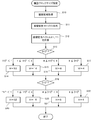
- 5 is a flowchart illustrating an example of an operation of setting a drawing block size according to Embodiment 1.
- FIG. 5 is a flowchart illustrating an example of an image generation operation according to Embodiment 1. It is a figure explaining image cache read-out.
- FIG. 17 is a diagram for explaining image cache access in the case of making a scanning direction fixed and rotating a reference image 90 degrees.
- FIG. 17 is a diagram for explaining image cache access in the case of changing the scanning direction in accordance with the 90 ° rotation of the reference image according to the second embodiment.
- FIG. 16 is a diagram showing a relationship between coordinate conversion of a coordinate axis of a drawing area, an enlargement ratio, and a rotation angle according to a second embodiment. It is a figure which shows the relationship of the drawing block and image cache in case a rotation angle is small. It is a figure explaining image cache access in the case of rotating a reference image, without changing a scanning direction.
- FIG. 16 is a diagram showing a relationship between coordinate conversion of a coordinate axis of a drawing area, an enlargement ratio, and a rotation angle according to a second embodiment. It is a figure which shows the relationship of the drawing block and image cache in case a rotation angle is small. It is a figure explaining image cache access in the case
- FIG. 16 is a flowchart illustrating an example of drawing block size setting operation according to Embodiment 2.
- FIG. 16 is a flowchart illustrating an example of an image generation operation according to Embodiment 2.
- FIG. It is a block diagram showing an example of hardware constitutions of an image drawing device concerning an embodiment of the invention.
- the image drawing device 10 has a drawing command generation unit 11, an outline generation unit 12, a pixel generation unit 13, a coordinate conversion unit 14, an image cache 15, and a drawing process. It comprises a unit 16, a display unit 17, an external memory 20, a register 21 and a drawing block setting unit 22.
- the image drawing device 10 is, for example, an LSI provided with a microcomputer, a field programmable gate array (FPGA), a digital signal processor (DSP) or a dedicated logic circuit, a display device, an external memory device, etc. Configured
- the drawing command generation unit 11 receives the reference image to be displayed superimposed on the image being displayed (display image) and the drawing area specifying information specifying the drawing area which is the area to convert and display the reference image, A coordinate transformation matrix for transforming coordinates from the drawing area to the reference image is generated from the information specifying the drawing area and the drawing area.
- the drawing command generation unit 11 sets the generated coordinate conversion matrix in the register 21. Thereafter, the drawing command generation unit 11 issues a drawing command instructing start of drawing to each unit in the image drawing apparatus 10.
- the outline generation unit 12 receives the drawing area identification information from the drawing command generation unit 11, and generates outline coordinates (coordinate data defining the outline) defining the outline of the drawing area on the display image. .
- the contour generation unit 12 sends contour coordinates to the pixel generation unit 13.
- the register 21 stores the coordinate conversion matrix created by the drawing command generation unit 11.
- the register 21 sends a coordinate conversion matrix to the drawing block setting unit 22 and the coordinate conversion unit 14 in response to a request.
- the drawing block setting unit 22 sets the number of vertical and horizontal pixels of the drawing block using the coordinate conversion matrix set in the register 21 and the size of a cache block described later before the start of the drawing process.
- the drawing block is a rectangular area covering the drawing area.
- the fact that the drawing block covers the drawing area basically means that the union of the pixels of the drawing block includes all the pixels of the drawing area.
- drawing blocks cover (divide) a drawing area without overlapping pixels. However, the pixels may overlap.
- the vertical and horizontal directions of the drawing block are in the direction of scanning of the display image. The setting of the drawing block size will be described in detail later.
- the pixel generation unit 13 receives the outline coordinates supplied from the outline generation unit 12 and the block information specifying the drawing block set by the drawing block setting unit 22, and the coordinates of the pixels inside the outline according to the outline coordinates and the block information.
- the calculated output coordinate data is sent to the coordinate conversion unit 14 one pixel at a time.
- the process of obtaining the coordinates (X, Y) of each pixel inside the outline is called a pixel generation process.
- the coordinate conversion unit 14 multiplies the coordinates generated by the pixel generation unit 13 by the coordinate conversion matrix to calculate the corresponding coordinates on the reference image.
- the coordinate conversion unit 14 also reads out the image data of the calculated coordinates from the external memory 20. Specifically, the coordinate conversion unit 14 checks whether or not the image data of the calculated coordinates is stored in the image cache 15. If the image data is stored, the image data is read from the image cache 15 and stored. If not, an image read request is issued to the external memory 20, and provision of image data is received via the image cache 15. Further, the coordinate conversion unit 14 issues, to the drawing processing unit 16, cache information composed of the number of the cache in which the read image data is stored and the address in the cache.
- the external memory 20 stores image data of a reference image.
- the points on the reference image are defined by the coordinate system of the reference image.
- the external memory 20 supplies the image data to the image cache 15 in accordance with the command from the coordinate conversion unit 14.
- the image cache 15 is composed of one or more cache blocks.
- the cache block stores image data of a rectangular area having a fixed number of pixels in the vertical and horizontal directions on the reference image.
- the image cache 15 reads and holds image data from the external memory 20 in units of blocks.
- the drawing processing unit 16 takes out the image data from the image cache 15 and generates an array of pixels to be displayed.
- the drawing processing unit 16 checks the image cache 15 and stores image data necessary for drawing in the image cache 15. Thereafter, the image drawing unit 16 reads out the reference image data and performs drawing processing on the read out reference image data.
- the image drawing unit 16 issues a display start instruction to the display unit 17.
- the display unit 17 displays the arrangement of pixels generated by the drawing processing unit 16 on the screen.
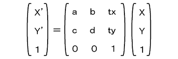
- FIG. 2 shows the affine transformation equation.
- the affine transformation is represented by a single coordinate transformation matrix that combines image scaling and rotation and translation.
- the coordinates (X ′, Y ′) after conversion are obtained by multiplying the coordinates (X, Y) before conversion by the coordinate conversion matrix (FIG. 2).
- Reference symbols a, b, c, d in the coordinate conversion matrix shown in FIG. 2 are elements for scaling, or rotating coordinates.
- tx and ty are elements for translating.
- coordinates (X, Y) are output coordinates (coordinates on the display image).
- coordinates (X ', Y') are coordinates of the reference image.
- the pixel generation unit 13 of FIG. 1 covers the drawing area with drawing blocks of the number of pixels in the vertical and horizontal directions of the drawing block set by the drawing block setting unit 22.
- the pixel generation unit 13 selects a drawing block in accordance with the scan. Thereafter, the pixel generation unit 13 scans pixels in the selected drawing block to obtain output coordinates in the display image.
- FIGS. 3A to 3D illustrate the conventional method in which the drawing block is fixed
- FIGS. 4A to 4D illustrate the method according to the present embodiment in which the size of the drawing block is appropriately changed.
- (a) represents a coordinate conversion matrix. Neither coordinate transformation matrix performs parallel translation of coordinate transformation.
- (B) shows a drawing block
- (c) shows a cache block of the image cache 15.
- the cache block is fixed by a rectangle of 16 pixels in width and 4 pixels in height, which is represented by a thick line in (c).
- the drawing block of the conventional method shown in (b) of FIGS. 3A to 3D is fixed as a square of 16 pixels in width and 16 pixels in height as represented by dotted lines.
- the drawing blocks shown in (b) of FIGS. 4A to 4D are appropriately resized so as to be represented by dotted lines.
- the small squares in (b) and (c) of FIGS. 3A-4D represent one pixel.
- the numbers in the pixels indicate the correspondence of pixels displayed as images from the cache block to the drawing block. For example, the "1" pixels of the cache block are displayed at the positions of the pixels of the same number "1" of the drawing block.
- the numbers in the pixels do not indicate the order of scanning in the drawing block.
- the direction of the main scan in the drawing block is indicated by the direction of the solid arrow.
- the direction of the sub scanning is indicated by a dotted arrow. It is assumed that the reference image has a size of 20 pixels in the horizontal direction.
- FIG. 3B shows the case where the enlargement ratio in the X direction of coordinate conversion is 2.0. That is, the size in the X direction of the image contained in the drawing block is doubled, and the reference image is displayed by being reduced to 1 ⁇ 2 in the lateral direction. Therefore, in the drawing process, 16 pixels in the X direction in one cache block are used only in one jump. For example, since the drawing block is 16 pixels horizontally, two cache blocks are used in the X direction each time one line in the X direction in the drawing block is scanned. Eight cache blocks are required to finish scanning for pixels included in one drawing block. As described above, when the conversion matrix of FIG. 3B (a) is used, cache utilization efficiency is reduced as compared with the case where the conversion matrix of FIG. 3A (a) is used.
- FIG. 3C shows the case where the enlargement ratio in the X direction of coordinate conversion is 0.5. That is, the size in the X direction of the image contained in the drawing block is set to 0.5, and the reference image is displayed by being doubled in the lateral direction. Of the 16 pixels in the X direction in one cache block, only pixel numbers 1 to 8 are used. Since the drawing block is 16 pixels wide, the other half of the pixels are not used. Thereafter, when the pixel generation processing moves to the drawing block next to the right of the drawing block currently being scanned, pixel numbers 9 to 16 are used. However, at this time, necessary data may have already been discarded from the image cache 15. In that case, it is necessary to read the same area from the external memory 20 to the image cache 15 again. Thus, expansion can increase memory access.
- FIG. 3D shows the case where the reference image is rotated 90 degrees counterclockwise.
- the pixels in the drawing block are scanned in the horizontal direction (solid line arrow of (b))
- the pixels are scanned in the vertical direction (solid line arrow of (c)).
- the cache block is four times longer in the horizontal direction than in the vertical direction. Therefore, four cache blocks are used in the vertical direction each time one horizontal line in the drawing block is scanned. For this reason, the rotation process reduces cache efficiency and increases memory access.
- FIGS. 4A to 4D show an example in which the size of the drawing block and the scanning direction are changed by the method of the present embodiment, as compared with FIGS. 3A to 3D describing the conventional method.
- FIG. 4A illustrates image cache access when image conversion is not performed.
- FIG. 4A is the same as FIG. 3A.
- FIG. 4B shows the case where the enlargement ratio of the coordinate conversion in the X direction is 2.0.
- the reference image is displayed by being reduced to 1 ⁇ 2 in the lateral direction. Therefore, if the number of horizontal pixels of the drawing block is halved to eight, two cache blocks are not used in the X direction.
- FIG. 3B since the number of horizontal pixels of the drawing block is 16, two cache blocks are used to draw one line of the drawing block.
- FIG. 4B as in FIG. 4A, only one cache block is used to draw one line of the drawing block. As a result, cache efficiency is improved as compared to FIG. 3B.
- FIG. 4C shows the case where the enlargement factor of the coordinate conversion in the X direction is 0.5, so that the reference image is displayed by being doubled in the lateral direction.
- the number of horizontal pixels of the drawing block is 16
- the number of horizontal pixels of the drawing block is doubled to 32.
- the pixel numbers 1 to 16 of the cache block are used without waste. Therefore, the memory access for reading out the same pixel data is performed again. As a result, the memory access amount is reduced as compared to the case of FIG. 3C.
- FIG. 4D shows the case where the coordinate conversion rotates 90 degrees clockwise.
- the drawing block used for the rotation process is set to 16 horizontal pixels and 16 vertical pixels. Therefore, scanning one drawing block in the main scanning direction results in using four cache blocks. Therefore, in FIG. 4D, the area obtained by subjecting the drawing block to coordinate conversion is set to 4 horizontal pixels and 16 vertical pixels so as to match the cache block. Then, even if the pixels of the drawing block are scanned one line in the main scanning direction, it is sufficient to use only one cache block. As a result, compared to the case shown in FIG. 3D, cache use efficiency and memory access amount are reduced.
- the block size is increased when the enlargement ratio of the coordinate conversion is small, and the block size is decreased when the enlargement ratio is large.
- the image cache 15 is used efficiently.
- the image cache 15 can be efficiently used by setting the number of vertical and horizontal pixels of the drawing block in accordance with the rotation of coordinate conversion.
- the cache efficiency can be improved and the memory access amount can be reduced as compared with the case shown with reference to FIGS. 3A to 3D. As a result, drawing can be performed faster.
- the image processing apparatus 10 increases the block size when the enlargement ratio of the coordinate conversion is small, and reduces the block size when the enlargement ratio is large.
- the image cache 15 is used efficiently.
- a, b, c, d of the coordinate conversion matrix of FIG. 2 are elements representing enlargement / reduction / rotation.
- the block size is changed in accordance with the enlargement factor representing the enlargement / reduction of the coordinate transformation of the elements.
- the number of pixels of the drawing block is set larger when the enlargement ratio is smaller and smaller when the enlargement ratio is larger than in the cases of FIGS. 3A to 3D.
- the number of pixels in the vertical and horizontal directions of the drawing block is such that the area obtained by coordinate converting the drawing block satisfies a predetermined relationship described later with the rectangular area on the drawing area to which the cache block corresponds.
- setting that the predetermined relationship is satisfied means using the cache when performing the same image conversion as compared with the case where the drawing block size illustrated in FIGS. 3A to 3D is not converted.
- the setting may be fixed in advance based on an experiment or the like. Also, the setting may be performed dynamically. For example, the size of the drawing block to be set may be determined based on a certain parameter.
- the size of the drawing block to be set can be set for each image conversion matrix. Specifically, when one pixel (for unit vector) is scanned in the X-axis direction and the Y-axis direction on the drawing block, how many pixels move on the reference image is set based on this enlargement ratio as the enlargement ratio It is possible to set the size of the drawing block to be. This example will be described later with reference to FIG.
- the enlargement factor of X is represented by the magnitude of the vector X1
- the enlargement factor of Y is represented by the magnitude of the vector Y1.
- X1 (a, c)
- the image processing apparatus 10 When there is a request for drawing from the outside, the image processing apparatus 10 starts the drawing block size setting process.
- the drawing command generation unit 11 acquires information for specifying a reference image and a drawing area (step S10), generates a coordinate conversion matrix, and stores the coordinate conversion matrix in the register 21 (step S11).
- the drawing block setting unit 22 calculates coordinate conversion vectors X1 and Y1 from the coordinate conversion matrix (step S12).
- coordinate conversion vectors X1 and Y1 are vectors obtained by coordinate converting unit vectors of coordinate axes X and Y of the drawing area. Then, the magnitude of the coordinate conversion vector X1 is determined.
- the number W of pixels in the horizontal direction of the drawing block is set using a squared value in order to avoid processing of the square root which increases the amount of calculation.
- FIG. 5 shows an example in which the number W of horizontal pixels of the drawing block can be selected from four types of 4, 8, 16 and 32 when the number of horizontal pixels of the cache block is 16. That is, when
- FIG. 5 shows an example in which the vertical pixel number H of the drawing block can be selected from four types of 4, 8, 16 and 32. That is, when
- 2 is smaller than 1, H 32 (step S19), and when
- 2 is 1 or more and less than 4, H 16 (step S20),
- the number of stages of each pixel number may be smaller or larger than the example of FIG.
- continuous settings may be used in accordance with the magnitudes of the coordinate conversion vectors X1 and Y1. Further, the number of stages of setting of the number of vertical and horizontal pixels may not be the same.
- the image processing apparatus 10 starts the drawing process shown in FIG. First, the contour generation unit 12 generates a contour of a reference image (step S30). Subsequently, the pixel generation unit 13 starts pixel generation.
- a drawing block which covers the drawing area is set with the drawing block size determined in FIG. 5 (S30).
- the set drawing block is selected for each row (S31).
- the inner loop (S32 to S39) is executed on the selected block row.
- This loop processing is executed the number of blocks (drawing area Y loop: outermost loop) in the Y direction (sub scanning direction) (loop of steps S31 to S40).
- drawing blocks are selected in the main scanning direction for one row of drawing blocks.
- a block is selected along the X direction (main scanning direction) (S32). Further inner loop processing (S33 to S38) is performed on the selected block. When the process in the selected block is completed, the next block is selected and the process is continued.
- This loop processing is performed the number of blocks in the X direction (drawing area X loop: loop inside block processing) (loop of steps S32 to S39).
- the number of lines per drawing block (the number of blocks in the X direction) may differ depending on the shape and inclination of the drawing area.
- processing is performed on one block selected in S31 and S32 (S33 to S38).
- the pixels in the drawing block are selected row by row (S33), and the number of times of the number H of pixels in the Y direction (sub scanning direction) loop processing (in-block Y loop: outside of in-block processing A loop) is performed (loop of step S33 to step S38).
- loop processing (block X loop: innermost loop) of the number of pixels W in one selected row is performed (steps S34 to S37). That is, pixels are selected one by one in the X direction (main scanning direction), coordinate conversion is performed (step S35), and drawing processing is performed (step S36). These processes are performed for the number of pixels W in one row.
- pixel generation ends and drawing is completed.
- the image drawing device 10 has the following effects.
- the first effect is that the cache can be used more efficiently, thereby improving the cache hit rate over the cases shown in FIGS. 3A-3D.
- the second effect is that the cache hit rate is improved, so the number of cache updates is reduced and the amount of memory access is reduced. As a result, it is possible to provide an image drawing device that draws at high speed.
- the scanning direction of the drawing area is changed according to the rotation angle of coordinate conversion.
- the configuration of the image drawing device 10 of the second embodiment is the same as that of FIG.
- the second embodiment differs from the first embodiment in that the drawing block setting unit 22 sets the scanning direction of the drawing area in addition to the setting of the drawing block size.
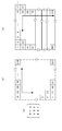
- FIG. 7 illustrates image cache readout.
- Four squares in (a) of FIG. 7 represent drawing blocks.
- FIGS. 7B and 7D (the middle column) show the relationship between the drawing block obtained by coordinate-converting the drawing block of FIG. 7A and the image cache 15.
- the bold dashed square represents the drawing block
- the thin solid rectangle represents the image cache.
- (C) and (e) (right column) in FIG. 7 indicate the directions of the images actually drawn, corresponding to the coordinate transformations in (b) and (d), respectively.
- (B) and (c) show the case where the rotation of coordinate conversion is 0 degree.
- (D) and (e) represent the case where the rotation of coordinate conversion is 90 degrees clockwise.
- the drawing block numbers are represented by square numbers.
- the block numbers of the image cache 15 are represented by parentheses.
- the size of the drawing block is 16 horizontal pixels by 16 vertical pixels.
- the cache block corresponds to a drawing area of 16 pixels wide and 8 pixels high.
- the solid arrows in the drawing block indicate the direction of the main scan in the drawing block.
- dotted arrows indicate the sub-scanning direction.
- (B) and (c) of FIG. 7 are the cases where the enlargement ratio is 1 and the rotation angle is 0 degree.
- the data of blocks (1) to (6) of the image cache are referred to. That is, if the rotation process is not performed, the reference image can be drawn by reading data from the external memory 20 to the image cache 15 six times.
- FIG. 7 show the case where the enlargement ratio of coordinate conversion is 1 and the rotation angle is 90 degrees in the clockwise direction.
- the drawing block of the number [1] four blocks of the numbers (1) to (4) of the image cache 15 are read.
- drawing a drawing block of number [2] four blocks are read out.
- eight readings are required when drawing drawing blocks of numbers [1] and [2]. Therefore, drawing speed falls.
- the drawing block setting unit 22 determines the vertical direction of the drawing area when the rotation angle (the smaller one of the angle formed by the horizontal direction of the image cache 15 and the direction of coordinate conversion in the horizontal direction of the drawing area is smaller than 45 degrees).
- the direction is the main scanning direction
- the horizontal direction is the sub-scanning direction.
- FIGS. 8A and 8B are diagrams for explaining the relationship between the scan direction and the access to the cache block.
- 8A and 8B as in FIGS. 3A to 4D, (a) shows a coordinate conversion matrix, (b) shows a drawing block, and (c) shows the configuration of the image cache 15.
- the small squares in (b) and (c) of FIGS. 8A and 8B represent pixels.
- the numbers in the pixels indicate the correspondence between the drawing block and the pixels of the image cache 15.
- the solid arrows indicate the main scanning direction, and the dotted arrows indicate the sub scanning direction.
- the cache block is a rectangle of 16 pixels in width and 4 pixels in height.
- the drawing block is a square of 16 pixels wide and 16 pixels high.
- FIG. 8A illustrates image cache access in the case where the reference image is rotated 90 degrees counterclockwise while the scanning direction is fixed.
- FIG. 8A is the same as FIG. 3D.
- the pixels in the drawing block are scanned in the horizontal direction (solid line arrow of (b))
- the pixels in the image cache 15 are scanned in the vertical direction (solid line arrow of (c)).
- Cache blocks are longer in the horizontal direction. Therefore, when the pixels are scanned in the vertical direction, four cache blocks are used in the vertical direction each time the pixels in one horizontal line in the drawing block are scanned.
- FIG. 8B illustrates image cache access in the case where the scan direction is changed in accordance with the 90-degree rotation of the reference image.
- the rotation angle of coordinate conversion is 90 degrees
- the vertical direction of the drawing area is taken as the main scanning direction
- the horizontal direction is taken as the sub-scanning direction.
- the pixels in the drawing block are scanned in the vertical direction (solid arrow in (b))
- in the image cache 15 they are scanned in the horizontal direction (solid arrow in (c)).
- scanning of the pixels of the drawing block falls within the cache block. Therefore, unlike the case of FIG. 8A, it is not necessary to use two or more cache blocks in the vertical direction.
- the main scan is performed in the horizontal direction from left to right toward the screen, and the sub-scan is performed in the vertical direction from top to bottom toward the screen.
- the direction of the main scan may be from right to left, or the direction of the sub-scan may be from bottom to top.
- the main scanning and sub scanning directions are switched, and the main scanning is vertically directed to the screen from top to bottom, and the sub scanning is horizontally directed to the screen Head left to right.
- the direction of the main scan in the case of changing may be a direction from the bottom toward the top toward the screen as long as it is a vertical direction. Further, as long as the direction of the sub scanning is horizontal, it may be a direction from the right toward the left toward the screen.
- the enlargement factor of coordinate conversion can be determined by the size of coordinate conversion vectors X1 and Y1.
- the rotation angle can be obtained from a vector obtained by subjecting a unit vector of coordinate axes X and Y of the drawing area to coordinate conversion.
- the rotation angle is generally determined using an inner product of vectors and the like. However, calculating the inner product increases the amount of calculation required. Therefore, it is substituted by a method which does not obtain the inner product. In the second embodiment, it is sufficient to obtain only whether the rotation angle is 45 degrees or more. This is because the scanning method in the X and Y directions to be determined in this embodiment can be determined. It can be determined by comparing the absolute value
- the solid circle in FIG. 9 is a unit circle.
- the vectors X1 and Y1 are vectors directed to points on the unit circle in FIG. That is, the size of X1 and Y1 represents the enlargement ratio.
- X1 is (a, c).
- the rotation angle is in the range of -180 degrees to 180 degrees, and when
- the drawing block setting unit 22 sets the number of vertical and horizontal pixels of the drawing block and the scanning direction from the coordinate conversion vectors X1 (a, c) and Y1 (b, d).
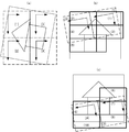
- FIG. 10 to FIG. 12 shows a drawing block of the drawing area.
- a solid frame represents a drawing area.
- a dashed rectangle represents a drawing block.
- (B) and (c) show the relationship between the coordinate block of the drawing block of (a) and the cache block.
- the dashed rectangles in (b) and (c) represent coordinate-transformed drawing blocks.
- the thick solid rectangles represent cache blocks.
- the thin solid frame represents the reference image.
- square brackets indicate the drawing block numbers.
- parenthesized numbers indicate the block numbers of the image cache 15.
- Solid arrows indicate the direction of main scanning, and dotted arrows indicate the direction of sub scanning.
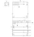
- FIG. 10 shows the relationship between the drawing block and the image cache when the rotation angle is less than 45 degrees.
- FIG. 10 shows, as an example, an example in the case where the reference image is rotated 10 degrees in the counterclockwise direction.
- the order of scanning of the drawing block of the drawing area is the order of [1] ⁇ [4].
- the main scanning direction of the pixels in the drawing block is the horizontal direction of the display image.
- cache blocks of (1) to (5) are read in the order of the numbers.
- the cache block read is required five times.
- the cache blocks (6) to (10) are read in that order to draw the drawing blocks of the numbers [3] and [4]. That is, in order to draw drawing blocks of numbers [1] to [4], ten cache block readings are required. The same applies to the case where the reference image is rotated 10 degrees clockwise.
- the hit rate of the image cache 15 does not change depending on whether the main scanning direction of the drawing block is the horizontal direction or the vertical direction of the display image. So, in the image drawing apparatus 10 of this Embodiment 2, when a rotation angle is 45 degrees or less, let the scanning direction of a drawing area be a horizontal direction of a display image.
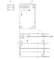
- FIGS. 11 and 12 show the case where the reference image is rotated 80 degrees counterclockwise.
- FIG. 11 illustrates image cache access when the scanning direction is not changed.
- the order of scanning of the drawing block is the order of [1] ⁇ [4] in which the main scan is horizontal.
- the main scanning direction of the pixels in the drawing block is the horizontal direction of the display image.
- cache blocks are read in the order of (1) to (7) in order to draw drawing blocks of numbers [1] and [2]. Seven cache block reads are required. Similarly, referring to FIG. 11C, the cache blocks (8) to (12) are read in that order in order to draw the drawing blocks of the numbers [3] and [4].
- the cache blocks of (8) to (10) and (12) of FIG. 11C are the same as the cache blocks of (3), (4), (7) and (6) of (b).
- the cache block of (9) is required, the cache block of (4) is discarded, so that the cache block of (9) is required to be read anew.
- the cache block of (12) is required, the cache block of (6) is discarded. Therefore, it is necessary to read the cache block of (12) again.
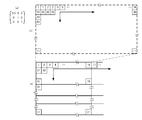
- FIG. 12 illustrates image cache access in the case of changing the scan direction in accordance with the rotation angle of the reference image.
- FIG. 12 shows an example in the case of rotating the reference image counterclockwise 80 degrees.
- the order of scanning of the drawing block is the order of [1] ⁇ [4] in which the main scan is vertical.
- the main scanning direction of the pixels in the drawing block is the vertical direction of the display image.
- cache blocks of (1) to (5) are read in the order of the numbers. Five cache block reads are required.
- cache blocks are read in the order of (6) to (10) in order to draw drawing blocks of numbers [3] and [4].
- the cache blocks of (6) and (8) of FIG. 12C are the same as the cache blocks of (3) and (5) of (b).
- the maximum number of cache blocks of the image cache 15 is four, there is a possibility that the cache block (3) still remains in the image cache 15 when the drawing of the drawing block of the number [3] is started. Therefore, in some cases, reading of the cache block of (6) is not required again.
- the cache block of (8) is needed, the cache block of (5) may remain, and in some cases, a new read is not needed.
- step S23 After setting the number of vertical and horizontal pixels of the drawing block, it is determined whether a and c of the vector X1 (a, c) satisfy
- the contour generation unit 12 generates a contour (step S30).
- the drawing block setting unit 22 determines whether the set main scanning direction is the X direction or the Y direction (step S50). If the main scanning direction is the X direction (step S50; X), a loop is executed first in the drawing area from the Y direction (steps S31 to S40). That is, processing similar to that of steps S31 to S40 in FIG. 6 is performed.
- step S50 If the main scanning direction is the Y direction (step S50; Y), a loop is executed first in the drawing area from the X direction (steps S51 to S60). That is, after exchanging the X direction and the Y direction of the processes of steps S31 to S40, the same processes as steps S31 to S40 of FIG. 6 are performed. In the processes of steps S51 to S60, four loops form a nested structure.
- a drawing block is set which divides and covers the drawing area. Thereafter, drawing blocks are selected column by column. An inner loop is performed on the selected block row. When the inner loop ends, the next column is selected. This loop process is performed for the number of blocks in the X direction (sub scanning direction) (drawing area X loop: outermost loop) (loop of steps 51 to S60).
- drawing blocks are selected in the main scanning (Y) direction for one row of drawing blocks. Further inner loop processing is performed on the selected block. When the process in the selected block is completed, the next block is selected.
- This loop process is performed for the number of blocks in the Y direction (main scanning direction) (drawing area Y loop: loop inside block process) (loop of steps S52 to S59).
- the number of drawing blocks per column may differ depending on the shape and inclination of the drawing area.
- processing is performed on each pixel in the selected one block.
- pixels in the drawing block are selected for each column.
- the inner loop is executed for the selected column, and when finished, the next column is selected.
- the loop processing (in-block X loop: loop outside of in-block processing) is performed for the number of pixels W in the X direction (sub-scanning direction) (loop of steps S53 to S58).
- loop processing (block Y loop: innermost loop) is performed on the selected row of pixels (steps S54 to S57). That is, pixels are selected one by one in the Y direction (main scanning direction), and coordinate conversion (step S55) and drawing processing (step S56) are performed. These processes are performed for the number of pixels H in one column.
- step S54 main scanning direction
- step S55 coordinate conversion
- drawing processing step S56
- the image drawing device 10 can use the image cache more efficiently when the reference image is rotated and displayed than when the scanning direction is not changed. As a result, the number of times of cache update and the amount of memory access are reduced compared to the case of FIG.
- FIG. 15 is a block diagram showing an example of the hardware configuration of the image drawing device 10 according to the embodiment of the present invention.
- the image drawing device 10 includes a control unit 31, a main storage unit 32, an external storage unit 33, an operation unit 34, a display unit 35, and a transmission / reception unit 36.
- the main storage unit 32, the external storage unit 33, the operation unit 34, the display unit 35, and the transmission / reception unit 36 are all connected to the control unit 31 via the internal bus 30.
- the control unit 31 is configured of a CPU (Central Processing Unit) or the like.
- the control unit 31 executes the processing of the image drawing device 10 in accordance with the control program 39 stored in the external storage unit 33.
- the main storage unit 32 is configured by a RAM (Random-Access Memory) or the like.
- the main storage unit 32 loads the control program 39 stored in the external storage unit 33 and is used as a work area of the control unit 31.
- the external storage unit 33 is composed of a non-volatile memory such as a flash memory, a hard disk, a DVD-RAM (Digital Versatile Disc Random-Access Memory), a DVD-RW (Digital Versatile Disc Rewritable) or the like.
- the external storage unit 33 stores in advance a control program 39 for causing the control unit 31 to perform the above-described processing. Further, according to the instruction of the control unit 31, the data stored by the control program 39 is supplied to the control unit 31, and the data supplied from the control unit 31 is stored.
- the external memory 20 of FIG. 1 is included in the external storage unit 33.
- the operation unit 34 includes a keyboard and a pointing device such as a mouse, and an interface device for connecting the keyboard and the pointing device to the internal bus 30.
- the image processing apparatus 10 receives an input of display of an image, designation of a reference image, information of a drawing area and coordinate conversion, and the like through the operation unit 34.
- the display unit 35 is configured of a CRT (Cathode Ray Tube) or an LCD (Liquid Crystal Display).
- the display unit 35 displays the display image generated by the drawing processing unit 16.
- the transmission / reception unit 36 is configured of communication devices and a serial interface or LAN (Local Area Network) interface connected to them.
- the transmitting and receiving unit 37 receives content including an image to be displayed from a server (not shown) through a network (not shown).
- the control program 39 of FIG. 15 uses the control unit 31, the main storage unit 32, the external storage unit 33, the operation unit 34, the display unit 35, the transmission / reception unit 36, etc.
- the processing relating to the pixel generation unit 13, the coordinate conversion unit 14, the image cache 15, the drawing processing unit 16, the display unit 17, the external memory 20, the register 21, and the drawing block setting unit 22 is performed.
- the setting unit is configured to set vertical and horizontal pixels of the rectangular area so that at least the first area falls within the range of the second area in accordance with the block size and the number of blocks of the image cache. It is characterized by setting the number.
- the setting unit sets pixels in the vertical and horizontal directions of the rectangular area so that the rectangular area becomes smaller as the rectangular area becomes smaller if the magnification of the coordinate conversion is large. It is characterized by setting the number.
- the conversion means is such that, when a smaller angle between a direction obtained by coordinate conversion of the horizontal direction of the drawing area and a horizontal direction of the second area exceeds 45 degrees,
- the present invention is characterized in that the main scanning direction and the sub scanning direction are interchanged, a rectangular area covering the drawing area is sequentially selected, and the selected rectangular area is scanned to select a pixel.
- the setting includes the length and width of the rectangular area such that at least the first area falls within the range of the second area in accordance with the block size and the number of blocks of the image cache. It is characterized in that the number of pixels is set.
- the setting is performed such that the rectangular area becomes smaller as the magnification of the coordinate conversion becomes larger, and the rectangular area becomes larger as the rectangular area becomes larger if the magnification is small. It is characterized in that the number of pixels is set.
- the calculating is performed in the scanning direction when a smaller angle between a direction obtained by performing coordinate conversion in the horizontal direction of the drawing area and the horizontal direction of the second area exceeds 45 degrees.
- the present invention is characterized in that the main scanning direction and the sub scanning direction are interchanged, a rectangular area covering the drawing area is selected in order, and the selected rectangular area is scanned to select a pixel.
- the main part to perform the image drawing process which comprises the control unit 31, the main storage unit 32, the external storage unit 33, the operation unit 34, the internal bus 30, etc., does not depend on a dedicated system, but uses a normal computer system. Is possible.
- a computer program for executing the above-mentioned operation is stored in a computer readable recording medium (flexible disc, CD-ROM, DVD-ROM, etc.) and distributed, and the computer program is installed in the computer.
- An image drawing apparatus may be configured to execute the above process.
- the computer program may be stored in a storage device of a server device on a communication network such as the Internet, and the image drawing device may be configured by downloading by a normal computer system.
- the computer program may be posted on a bulletin board (BBS, Bulletin Board System) on a communication network, and the computer program may be distributed via the network. Then, the computer program may be activated and executed in the same manner as other application programs under the control of the OS so that the above-described processing can be executed.
- BSS bulletin Board System
Landscapes
- Engineering & Computer Science (AREA)
- Physics & Mathematics (AREA)
- General Physics & Mathematics (AREA)
- Theoretical Computer Science (AREA)
- Multimedia (AREA)
- Signal Processing (AREA)
- Controls And Circuits For Display Device (AREA)
- Image Processing (AREA)
- Editing Of Facsimile Originals (AREA)
- Image Generation (AREA)
Abstract
描画コマンド発生部(11)は、表示画像中に参照画像を変換して表示する描画領域と座標変換の情報を取得し、座標変換マトリクスをレジスタ(21)にセットする。描画ブロック設定部(22)は、描画領域を分割して被覆する矩形領域を、描画領域から参照画像へ座標変換マトリクスで座標変換した領域が、参照画像を読み出した画像キャッシュ(15)の画像上の形に適合するように、矩形領域の縦と横の画素数を設定する。画素生成部(13)は、設定した矩形領域で描画領域を走査して画素の位置を生成し、座標変換部(14)は描画領域の画素に対応する参照画像の画素位置の画像データを外部メモリ(20)から読み出す。画像キャッシュ(15)は、外部メモリ(20)から読み出した画像データを蓄える。描画処理部(16)は、画像キャッシュ(15)から画像データを読み出して、描画領域の画素に変換する。
Description
本発明は、画像描画装置に関する。より詳しくは、参照画像を変換して表示画像上の描画領域に表示する画像描画装置、画像描画方法および記録媒体に関する。
コンピュータグラフィックスでは、元となる参照画像に回転などの変換を施して、表示画像に重ねて表示することが行われている。このような変換処理には、高速処理を必要とするものがある。そこで、参照画像を高速に変換する技術が種々提案されている。
例えば、特許文献1には、ラインベース形式で入力された画像データを、1画像分の画像データ容量よりも小さい容量のバッファメモリに一時記憶させ、ブロックインターリーブ形式で出力する画像処理装置が記載されている。
特許文献2には、1ラインのソースイメージデータを拡大して高速に描画する画像処理装置が記載されている。
特許文献3には、画像データを高速に回転処理する画像装置が記載されている。
特許文献4には、参照画像を座標変換し、得られた画像を補間する画像補間方法が記載されている。
また、特許文献5には、画像の回転処理を高速に行える2次元データ回転処理装置が記載されている。
参照画像に座標変換を行って表示する画描画写手順において、メモリから参照画像データを逐一取得するのでは、データ転送に時間がかかる。そこで、参照画像をキャッシュメモリにプリフェッチし、さらに、キャッシュサイズを、そのアドレスが連続してアクセスされるように変更する等の処理を行うことによって高速に描画する描画技術が知られている。
この描画技術では、キャッシュメモリに格納されている参照画像の走査方向が表示画面の左上から右下の方向に固定されている。このため、画像を拡大・縮小・回転させた場合は、キャッシュのヒット率が低くなり、メモリへのアクセスの量が増え、画像を高速に描画できなくなってしまう。
本発明は、上述の事情に鑑みてなされたもので、座標変換によるキャッシュヒット率の低下の小さい画像描画装置、画像描画方法および記録媒体を提供することを目的とする。
また、本発明は、参照画像を変換して高速に画像を描画できる画像描画装置、画像描画方法および記録媒体を提供することを他の目的とする。
また、本発明は、参照画像を変換して高速に画像を描画できる画像描画装置、画像描画方法および記録媒体を提供することを他の目的とする。
本発明の第1の観点に係る画像描画装置は、
参照画像を変換して表示する領域である描画領域を、表示画像中に、指定する情報を取得する描画領域取得手段と、
前記描画領域に前記参照画像を変換して表示するための、前記描画領域の座標から前記参照画像の座標への座標変換を特定する情報を取得する座標変換情報取得手段と、
前記描画領域を被覆する矩形領域を前記座標変換して得られる第1の領域と、前記参照画像を蓄えている画像キャッシュに記憶されている画像データに対応し且つ前記参照画像上に位置する第2の領域とが、所定の関係を充足するように、前記矩形領域の縦と横の画素数を設定する設定手段と、
前記設定手段で設定した縦と横の画素数で前記描画領域を被覆する1以上の前記矩形領域を生成する生成手段と、
所定の走査方向の順に前記矩形領域を選択し、該選択した矩形領域内の走査方向に順番に選択した画素から前記座標変換によって前記参照画像内における画素位置を算出する変換手段と、
前記変換手段で算出した画素位置における画像データを、前記参照画像を記憶しているメモリから読み出す画像取得手段と、
前記メモリから読み出した画像データを蓄える前記画像キャッシュと、
前記画像キャッシュから前記画像データを読み出して、前記描画領域の画素に変換する描画手段と、
を備える。
本発明の第2の観点に係る画像描画装置は、
参照画像を変換して表示する領域である描画領域を、表示画像中に、指定する情報を取得する描画領域取得手段と、
前記描画領域に前記参照画像を変換して表示するための、前記描画領域の座標から前記参照画像の座標への座標変換を特定する情報を取得する座標変換情報取得手段と、
前記描画領域を被覆する矩形領域を設定する設定手段と、
前記設定手段で設定した矩形領域で前記描画領域を被覆する1以上の前記矩形領域を生成する生成手段と、
所定の走査方向の順に前記矩形領域を選択し、該選択した矩形領域内の走査方向に順番に選択した画素から前記座標変換によって前記参照画像内における画素位置を算出する変換手段と、
前記変換手段で算出した画素位置における画像データを、前記参照画像を記憶しているメモリから読み出す画像取得手段と、
前記メモリから読み出した画像データを蓄える前記画像キャッシュと、
前記画像キャッシュから前記画像データを読み出して、前記描画領域の画素に変換する描画手段と、
を備え、
前記変換手段は、前記描画領域の水平方向を座標変換した方向と、前記第2の領域の水平方向と、のなす角度の小さい方が45度を超える場合に、前記走査方向の、主走査の方向と副走査の方向を入れ替えて、前記描画領域を被覆する矩形領域を順に選択し、かつ、選択した矩形領域内を走査して画素を選択する。
本発明の第3の観点に係る画像描画方法は、
参照画像を変換して表示する領域である描画領域を、表示画像中に、指定する情報を取得し、
前記描画領域に前記参照画像を変換して表示するための、前記描画領域の座標から前記参照画像の座標への座標変換を特定する情報を取得し、
前記描画領域を被覆する矩形領域を前記座標変換して得られる第1の領域と、前記参照画像を蓄えている画像キャッシュに記憶されている画像データに対応し且つ前記参照画像上に位置する第2の領域とが、所定関係を充足するように、前記矩形領域のサイズを設定し、
設定したサイズで前記描画領域を被覆する1以上の前記矩形領域を生成し、
所定の走査方向に、順に、前記矩形領域を選択し、該選択した矩形領域内の走査方向の順番に選択した画素から前記座標変換によって前記参照画像内における画素位置を算出し、
算出した画素位置における画像データを読み出し、
読み出した画像データを画像キャッシュに蓄え、
前記画像キャッシュから前記画像データを読み出して、前記描画領域の画素に変換する。
本発明の第4の観点に係る画像描画方法は、
参照画像を変換して表示する領域である描画領域を、表示画像中に、指定する情報を取得し、
前記描画領域に前記参照画像を変換して表示するための、前記描画領域の座標から前記参照画像の座標への座標変換を特定する情報を取得し、
前記描画領域を被覆する矩形領域を設定し、
設定した矩形領域で前記描画領域を被覆する1以上の前記矩形領域を生成し、
所定の走査方向に、順に、前記矩形領域を選択し、該選択した矩形領域内の走査方向の順番に選択した画素から前記座標変換によって前記参照画像内における画素位置を算出し、
算出した画素位置における画像データを読み出し、
読み出した画像データを画像キャッシュに蓄え、
前記画像キャッシュから前記画像データを読み出し、前記描画領域の水平方向を座標変換した方向と、前記第2の領域の水平方向と、のなす角度の小さい方が45度を超える場合に、前記走査方向のうちの主走査の方向と副走査の方向を入れ替えて、前記描画領域を被覆する矩形領域を順に選択し、かつ、選択した矩形領域内を走査して画素を選択する。
本発明の第5の観点に係るコンピュータ読み取り可能な記録媒体に記録されたプログラムは、コンピュータに、
参照画像を変換して表示する領域である描画領域を、表示画像中に、指定する情報を取得する処理、
前記描画領域に前記参照画像を変換して表示するための、前記描画領域の座標から前記参照画像の座標への座標変換を特定する情報を取得する処理、
前記描画領域を被覆する矩形領域を前記座標変換して得られる第1の領域と、前記参照画像を蓄えている画像キャッシュに記憶されている画像データに対応し且つ前記参照画像上に位置する第2の領域とが、とが、所定の関係を充足するように、前記矩形領域のサイズを設定する処理、
設定したサイズで前記描画領域を被覆する1以上の前記矩形領域を生成する処理、
所定の走査方向に、順に、前記矩形領域を選択し、該選択した矩形領域内の走査方向の順番に選択した画素から前記座標変換によって前記参照画像内における画素位置を算出する処理、
算出した画素位置における画像データを読み出す処理、
読み出した画像データを画像キャッシュに蓄える処理、
前記画像キャッシュから前記画像データを読み出して、前記描画領域の画素に変換する処理、
を実行させる。
本発明の第6の観点に係るコンピュータ読み取り可能な記録媒体に記録されたプログラムは、コンピュータに、
参照画像を変換して表示する領域である描画領域を、表示画像中に、指定する情報を取得する処理、
前記描画領域に前記参照画像を変換して表示するための、前記描画領域の座標から前記参照画像の座標への座標変換を特定する情報を取得する処理、
前記描画領域を被覆する矩形領域を設定する処理、
設定した矩形領域で前記描画領域を被覆する1以上の前記矩形領域を生成する処理、
所定の走査方向に、順に、前記矩形領域を選択し、該選択した矩形領域内の走査方向の順番に選択した画素から前記座標変換によって前記参照画像内における画素位置を算出する処理、
算出した画素位置における画像データを読み出す処理、
読み出した画像データを画像キャッシュに蓄える処理、
前記画像キャッシュから前記画像データを読み出し、前記描画領域の水平方向を座標変換した方向と、前記第2の領域の水平方向と、のなす角度の小さい方が45度を超える場合に、前記走査方向のうちの主走査の方向と副走査の方向を入れ替えて、前記描画領域を被覆する矩形領域を順に選択し、かつ、選択した矩形領域内を走査して画素を選択する処理、
を実行させる。
本発明によれば、キャッシュが効率的に使用できるようになる。その結果、キャッシュヒット率の低下を軽減することにより、参照画像を変換して表示させる場合の描画を高速に行える。
以下、本発明の実施の形態について図を参照して説明する。なお、図中同一または相当する部分には同じ符号を付す。
(実施の形態1)
実施の形態1の画像描画装置10は、機能的には、図1に示すように、描画コマンド発生部11、輪郭生成部12、画素生成部13、座標変換部14、画像キャッシュ15、描画処理部16、表示部17、外部メモリ20、レジスタ21および描画ブロック設定部22を備える。
画像描画装置10は、一方、ハードウェア的には、例えばマイクロコンピュータ、FPGA(Field Programmable Gate Array)、DSP(Digital Signal Processor)または専用の論理回路を備えるLSIと、表示装置、外部メモリ装置等から構成される。
実施の形態1の画像描画装置10は、機能的には、図1に示すように、描画コマンド発生部11、輪郭生成部12、画素生成部13、座標変換部14、画像キャッシュ15、描画処理部16、表示部17、外部メモリ20、レジスタ21および描画ブロック設定部22を備える。
画像描画装置10は、一方、ハードウェア的には、例えばマイクロコンピュータ、FPGA(Field Programmable Gate Array)、DSP(Digital Signal Processor)または専用の論理回路を備えるLSIと、表示装置、外部メモリ装置等から構成される。
描画コマンド発生部11は、表示中の画像(表示画像)に重ねて表示する参照画像と、参照画像を変換して表示する領域である描画領域を特定する描画領域特定情報を受けて、参照画像と描画領域を特定する情報とから、描画領域から参照画像へ座標を変換する座標変換マトリクスを生成する。描画コマンド発生部11は、生成した座標変換マトリクスをレジスタ21に設定する。その後、描画コマンド発生部11は、描画の開始を指示する描画コマンドを、画像描画装置10内の各部に発行する。
輪郭生成部12は、描画コマンドに応答し、描画コマンド発生部11から描画領域特定情報を受けて、表示画像上の描画領域の輪郭を定義する輪郭座標(輪郭を定義する座標データ)を生成する。輪郭生成部12は、画素生成部13に、輪郭座標を送る。
レジスタ21は、描画コマンド発生部11が作成した座標変換マトリクスを記憶する。レジスタ21は、要求に応じて、描画ブロック設定部22と座標変換部14に座標変換マトリクスを送る。
描画ブロック設定部22は、描画処理開始前に、レジスタ21に設定された座標変換マトリクスと後述するキャッシュブロックのサイズとを用いて描画ブロックの縦と横の画素数を設定する。ここで、描画ブロックは、描画領域を被覆する矩形の領域である。描画ブロックが描画領域を被覆するとは、基本的には、描画ブロックの画素の和集合が、描画領域の全ての画素を含むことをいう。例外として、参照画像に無効な画素がある場合など、描画領域の画素のうち描画ブロックに含まれない画素が存在することがあり得る。一般には、描画ブロック同士は画素が重複することなく描画領域を被覆(分割)する。しかし、画素が重複していても構わない。描画ブロックの縦と横は、表示画像の走査の方向に沿っている。描画ブロックのサイズの設定については後に詳述する。
画素生成部13は、輪郭生成部12から供給された輪郭座標と描画ブロック設定部22が設定した描画ブロックを特定するブロック情報を受け取り、輪郭座標とブロック情報とに従って、輪郭内部の画素の座標を求め、座標変換部14に、生成した出力座標データを1画素ずつ送る。なお、輪郭の内部の各画素の座標(X,Y)を求める処理を画素生成処理と呼ぶ。
座標変換部14は、画素生成部13で生成された座標に座標変換マトリクスを乗算して、参照画像上の対応する座標を算出する。また、座標変換部14は、算出した座標の画像データを外部メモリ20から読み出す。具体的には、座標変換部14は、算出した座標の画像データが画像キャッシュ15に記憶されているか否かをチェックし、記憶されていれば、画像キャッシュ15から画像データを読み出し、記憶されていなければ、画像読み出しリクエストを外部メモリ20に発行し、画像キャッシュ15を介して画像データの提供を受ける。また、座標変換部14は、描画処理部16に、読み出した画像データが保存されているキャッシュの番号とそのキャッシュ内のアドレスとで構成されたキャッシュ情報をそれぞれ発行する。
外部メモリ20は、参照画像の画像データを記憶している。参照画像上の点は、参照画像の座標系によって定義される。外部メモリ20は、座標変換部14からの指令に従って、画像キャッシュ15に画像データを供給する。
画像キャッシュ15は、1または複数のキャッシュブロックから構成される。キャッシュブロックは、参照画像上の、縦横が一定の画素数からなる矩形領域の画像データを保存する。画像キャッシュ15は、外部メモリ20から、ブロック単位で画像データを読み出して保持する。
描画処理部16は、画像キャッシュ15から画像データを取り出して、表示する画素の並びを生成する。描画処理部16は、画像キャッシュ15をチェックし、画像キャッシュ15内に描画に必要な画像データを格納する。その後、画像描画部16は、参照画像データを読み出し、読み出した参照画像データに描画処理を行う。画像描画部16は、表示部17に表示開始命令を発行する。
表示部17は、描画処理部16で生成された画素の並びを画面に表示する。
次に、本実施の形態1において、画像変換部14で行われる一般的な座標変換の例について、図2を参照して説明する。図2は、アフィン変換の式を示す。アフィン変換は、画像の拡大・縮小と、回転および平行移動を組み合わせた1つの座標変換マトリクスで表される。変換前の座標(X,Y)に、座標変換マトリクスを乗算することにより、変換後の座標(X’,Y’)が得られる(図2)。図2に示す座標変換マトリクスのa,b,c,dは、座標を拡大・縮小または回転するための要素である。tx,tyは平行移動をするための要素である。この式を座標変換部14での座標変換にあてはめると、座標(X,Y)が出力座標(表示画像上の座標)である。一方、座標(X’,Y’)が参照画像の座標である。
図1の画素生成部13は、描画ブロック設定部22が設定した描画ブロックの縦と横の画素数の描画ブロックで、描画領域を被覆する。画素生成部13は、走査に従って描画ブロックを選択する。その後、画素生成部13は、選択した描画ブロックの中の画素を走査して、表示画像中の出力座標を求める。
次に、座標変換部14と画像処理部16とが実行する、画像キャッシュ15から参照画像を読み出して画像変換を施して、描画ブロック設定部22で設定された描画ブロックに展開する処理を説明する。
理解を容易にするため、始めに、描画ブロック設定部22で設定された描画ブロックと、画像キャッシュ15上の参照画像を記憶しているキャッシュブロックと、画像変換との関係について、従来と本実施形態とを、図3A~図4Dを参照して対比して説明する。
図3A~3Dは、描画ブロックが固定の従来の手法を説明し、図4A~4Dは、描画ブロックのサイズを適宜変更する本実施形態にかかる手法を説明するためのものである。
なお、以下の図3A~4Dで、(a)は座標変換マトリクスを表す。いずれの座標変換マトリクスも、座標変換の平行移動は行わない。(b)は描画ブロックを示し、(c)は画像キャッシュ15のキャッシュブロックを示す。
図3A~3Dは、描画ブロックが固定の従来の手法を説明し、図4A~4Dは、描画ブロックのサイズを適宜変更する本実施形態にかかる手法を説明するためのものである。
なお、以下の図3A~4Dで、(a)は座標変換マトリクスを表す。いずれの座標変換マトリクスも、座標変換の平行移動は行わない。(b)は描画ブロックを示し、(c)は画像キャッシュ15のキャッシュブロックを示す。
図3A~図4Dでは、キャッシュブロックは、(c)において太線で表される、横16画素、縦4画素の長方形で固定である。一方、図3A~3Dの(b)に示されている従来手法の描画ブロックは、点線で表されるように、横16画素、縦16画素の正方形で固定である。一方、図4A~図4Dの(b)に示されている描画ブロックは、点線で表されるように適宜サイズが変更される。
図3A~図4Dの(b)と(c)の小さい正方形は、1つの画素を表す。画素中の番号は、キャッシュブロックから描画ブロックへ画像表示される画素の対応を示す。例えばキャッシュブロックの“1”の画素は、描画ブロックの同じ番号“1”の画素の位置に表示される。画素中の番号は、描画ブロック内の走査の順序を示すものではない。描画ブロック内の主走査の方向は実線の矢印の方向で示される。一方、副走査の方向は点線の矢印で示される。
なお、参照画像は、横方向に20画素のサイズを有していると仮定する。
なお、参照画像は、横方向に20画素のサイズを有していると仮定する。
拡大率が1、回転角度が0度の場合を、図3Aを参照して説明する。
拡大率が1,回転角度が0の場合は、描画ブロック(b)の主走査を一行(画素1~16)行うと、一つのキャッシュブロックの一行のデータ(画素1~16)が過不足なく読み込まれる。主走査と副走査を行って、一つの描画ブロックに含まれる画素について走査を終えるためには、4つのキャッシュブロックが必要となる。
拡大率が1,回転角度が0の場合は、描画ブロック(b)の主走査を一行(画素1~16)行うと、一つのキャッシュブロックの一行のデータ(画素1~16)が過不足なく読み込まれる。主走査と副走査を行って、一つの描画ブロックに含まれる画素について走査を終えるためには、4つのキャッシュブロックが必要となる。
図3Bは、座標変換のX方向の拡大率が2.0の場合を示す。つまり、描画ブロック内に納める画像のX方向のサイズを2倍とするものであり、参照画像は横方向に1/2に縮小されて表示される。したがって、描画処理では、1つのキャッシュブロック内のX方向16画素は、1つ飛びでしか使用されない。例えば、描画ブロックは横16画素であるので、描画ブロック内のX方向1ライン分が走査されるたびに、キャッシュブロックは、X方向に2つ使用されることになる。一つの描画ブロックに含まれる画素について走査を終えるためには、8つのキャッシュブロックが必要となる。このように、図3B(a)の変換マトリクスを使用する場合には、図3A(a)の変換マトリクスを使用する場合と比較して、キャッシュ利用効率が低下する。
図3Cは、座標変換のX方向の拡大率が0.5の場合を示す。つまり、描画ブロック内に納める画像のX方向のサイズを0.5倍とするものであり、参照画像は横方向に2倍に拡大されて表示される。1つのキャッシュブロック内のX方向16画素のうち、画素番号1~8だけが使用される。描画ブロックは横16画素であるので、残りの半分の画素は使用されない。その後、現在走査している描画ブロックの右隣の描画ブロックに画素生成処理が移ると、画素番号9~16が使用される。しかし、このときには、すでに画像キャッシュ15から必要なデータが破棄されている可能性がある。その場合、再度、同じ領域を外部メモリ20から画像キャッシュ15へ読み出す必要がある。このように、拡大によって、メモリアクセスが増加する可能性がある。
図3Dは、参照画像を反時計方向に90度回転した場合を示す。描画ブロック内の画素が横((b)の実線矢印)方向に走査されると、画像キャッシュ15内では、縦((c)の実線矢印)方向に走査される。実施の形態1では、キャッシュブロックは、横方向が、縦方向の4倍長い。そのため、描画ブロック内の横方向1ラインが走査されるたびに、縦方向に4つのキャッシュブロックが使用される。このため、回転処理によってキャッシュ効率は低下し、メモリアクセスが増大する。
図4A~図4Dは、従来の手法を説明している図3A~図3Dに対して、本実施の形態の方法で走査方向、描画ブロックのサイズを変更した場合の例を示す。図4Aは、画像変換を行わない場合の画像キャッシュアクセスを説明する。
図4Aは、図3Aと同じである。
図4Bは、座標変換のX方向の拡大率が2.0の場合である。参照画像は横方向に1/2に縮小されて表示される。そこで、描画ブロックの横画素数を半分の8にすれば、キャッシュブロックがX方向に2つ使用されなくなる。図3Bにおいては、描画ブロックの横の画素数が16であったため、描画ブロックの一行を描画するために、キャッシュブロックを2個使用した。一方、図4Bにおいては、図4Aと同じように、描画ブロックの一行を描画するために、キャッシュブロックは1個のみが使用される。その結果、図3Bと比較して、キャッシュ効率が向上する。
図4Cは、座標変換のX方向の拡大率が0.5の場合を示すよって、参照画像は横方向に2倍に拡大されて表示される。図3Cの例では、描画ブロックの横の画素数が16であったので、キャッシュブロックに記録された画素のデータの半分が使用されずに破棄されていた。そこで、図4Cの例では、描画ブロックの横画素数を2倍の32とした。これにより、キャッシュブロックの画素番号1~16までが無駄無く使用さる。よって、再度、同じ画素データを読み出すメモリアクセスが行ない。その結果、図3Cの場合と比較して、メモリアクセス量が減少する。
図4Dは、座標変換が時計方向に90度回転する場合を示す。図3Dにおいては、回転処理を行う際の描画ブロックを、横16画素、縦16画素として処理を行った。そのため、描画ブロックを主走査方向に1行走査すると、キャッシュブロックを4つ使用することとなった。そこで、図4Dにおいては、描画ブロックを座標変換した領域が、キャッシュブロックに合致するように、横4画素、縦16画素に設定される。そうすると、描画ブロックの画素を主走査方向に一行走査しても、キャッシュブロックは1つ使用するだけで足りる。その結果、図3Dで示した場合より、キャッシュ使用効率とメモリアクセス量が減少している。
以上で示したように、図4A~4Dを参照して説明したように、座標変換の拡大率が小さいときは、ブロックサイズを大きく、拡大率が大きいときは、ブロックサイズを小さくすることにより、画像キャッシュ15が効率よく使用される。また、座標変換の回転に合わせて、描画ブロックの縦と横の画素数を設定すれば画像キャッシュ15は効率よく使用される。このように、描画ブロックのサイズを変換マトリクスに対応して変更することにより、図3A~3Dを参照して示した場合よりも、キャッシュ効率が向上し、メモリアクセス量を低減できる。その結果、描画をより高速に行うことができる。
本実施形態の画像処理装置10は、図4A~4Dを参照して説明したように、座標変換の拡大率が小さいときは、ブロックサイズを大きく、拡大率が大きいときは、ブロックサイズを小さくすることにより、画像キャッシュ15を効率よく使用するものである。
次に、実際にどのように描画ブロックサイズの変更を行えばよいか説明する。本実施の形態1では、図2の座標変換マトリクスのa,b,c,dが拡大・縮小・回転を表す要素である。ブロックサイズは、その要素のうちの座標変換の拡大・縮小を表す拡大率に合わせて変更される。描画ブロックの画素数は、図3A~3Dの場合と比べ、拡大率が小さいときは大きく、拡大率が大きいときは小さく設定される。座標変換の回転を行う場合には、描画ブロックの縦と横の画素数は、描画ブロックを座標変換した領域が、キャッシュブロックが対応する描画領域上の矩形領域と、後述する所定の関係を満たすように設定される。ここで、所定の関係を満たすように設定されるとは、図3A~3Dで例示したような描画ブロックのサイズを変換しない場合と比較して、同一の画像変換を行う場合に、キャッシュの利用効率が少なくとも等しいか又はより効率が高くなるように描画ブロックを設定すること全般を含む。設定は、実験などに基づいて予め固定的に設定してもよい。また、設定を動的に行うようにしてもよい。例えば、あるパラメターに基づいて、設定すべき描画ブロックのサイズを求めるようにしてもよい。
例えば、画像変換マトリクス毎に、設定すべき描画ブロックのサイズを設定することができる。具体的には、描画ブロック上でX軸方向とY軸方向に1画素(単位ベクトル分)走査したときに、参照画像上で何画素動くかを拡大率として、この拡大率に基づいて、設定すべき描画ブロックのサイズを設定することが可能である。この例については、図5を参照して後述する。
一方、座標変換の拡大率は、描画領域の座標軸X、Yの単位ベクトルを座標変換したベクトルから求めることができる。すなわち出力座標(X,Y)=(0,0)から、X方向に1単位、Y方向に1単位進んだときに、参照座標(X’,Y’)がどれだけ移動したかを調べることで、拡大率を求められる。図2の座標変換式において、出力座標を(X,Y)=(1,0)としたときの参照座標(X’,Y’)を座標変換ベクトルX1、(X,Y)=(0,1)としたときの(X’,Y’)を座標変換ベクトルY1とする。Xの拡大率は、ベクトルX1の大きさ、Yの拡大率は、ベクトルY1の大きさで表される。ここで、図2の座標変換式に、(X,Y)=(1,0)、(X,Y)=(0,1)をそれぞれ代入すると、X1=(a,c)、Y1=(b,d)が求められる。これらのベクトルの大きさから、X方向の拡大率はa2+c2、Y方向の拡大率はb2+d2、の平方根となる。
次に、画像処理装置10の、拡大率を用いて行う描画ブロック設定動作と画像生成の動作等を含む画像処理動作を、図5及び6を使用して説明する。
外部から描画の要請があると、画像処理装置10は、描画ブロックサイズ設定処理を開始する。まず、描画コマンド発生部11は、参照画像と描画領域を指定する情報を取得し(ステップS10)、座標変換マトリクスを生成し、レジスタ21に格納する(ステップS11)。
描画ブロック設定部22は、座標変換マトリクスから座標変換ベクトルX1、Y1を計算する(ステップS12)。ここで、座標変換ベクトルX1、Y1は、描画領域の座標軸X、Yの単位ベクトルを座標変換したベクトルである。そして、座標変換ベクトルX1の大きさを求める。
ベクトルX1の大きさを求めるにあたり、計算量が増加する平方根の処理を回避するため、2乗した値を使用して、描画ブロックの横方向の画素数Wが設定される。次の処理は|X1|2の大きさによって分岐する(ステップS13)。図5はキャッシュブロックの横画素数が16の場合に、描画ブロックの横画素数Wを、4,8,16,32の4通りから選択可能な例を示している。すなわち、|X1|2が1より小さい場合は、W=32に(ステップS14)設定される。|X1|2が1以上4未満の場合は、W=16に(ステップS15)、|X1|2が4以上9未満の場合は、W=8に(ステップS16)、|X1|2が9以上の場合は、W=4に設定される(ステップS17)。
同様に、縦方向の画素数も設定がされる。すなわち、プロセスは|Y1|2の大きさによって分岐する(ステップS18)。図5は描画ブロックの縦画素数Hを、4,8,16,32の4通りから選択可能な例を示している。すなわち、|Y1|2が1より小さい場合は、H=32に(ステップS19)、|Y1|2が1以上4未満の場合は、H=16に(ステップS20)、|Y1|2が4以上9未満の場合は、H=8に(ステップS21)、|Y1|2が9以上の場合は、H=4に設定される(ステップS22)。そして、描画ブロックサイズ設定は終了される。
描画ブロックの縦と横の画素数をどのように設定するかは、上述の例に限らない。それぞれの画素数の段階は、図5の例示より少なくても多くてもよい。さらに、図5のような離散的な設定ではなく、座標変換ベクトルX1、Y1の大きさに合わせた連続的な設定であってもよい。また、縦と横の画素数の設定の段階の数は同じでなくてもよい。
なお、上述の図5の処理では、図4Dで説明したように、座標変換の回転角度に応じて、描画ブロックの縦と横の画素数は入れ替えられている。
描画ブロックサイズ設定が終了すると、画像処理装置10は、図6に示す描画処理を開始する。まず、輪郭生成部12が、参照画像の輪郭を生成する(ステップS30)。続いて、画素生成部13は画素生成を開始する。
図6のフローチャートでは、4つのループが入れ子構造をつくる。
まず、図5で決定した描画ブロックサイズで、描画領域を被覆する描画ブロックが設定される(S30)。次に、設定された描画ブロックが行ごとに選択される(S31)。選択したブロックの行に対して、内側のループ(S32~S39)が実行される。内側のループが終了すれば、次の行が選択され、処理が続行される。このループ処理はY方向(副走査方向)のブロック数の回数(描画領域Yループ:最も外側のループ)だけ実行される(ステップS31~ステップS40のループ)。描画領域Yループの処理は、描画ブロックの1つの行について、主走査の方向に描画ブロックが選択される。
次にX方向(主走査方向)に沿ってブロックが選択される(S32)。選択されたブロックに対してさらに内側のループ処理(S33~S38)が実行される。選択されたブロックにおける処理が終了すれば、次のブロックが選択され、処理が続行される。このループ処理は、X方向のブロック数の回数(描画領域Xループ:ブロック処理の内側のループ)おこなわれる(ステップS32~ステップS39のループ)。描画領域の形状と傾きによって、描画ブロックの行ごとの数(X方向のブロック数)は異なる場合がある。
次に、S31とS32において選択された一のブロックに対して、処理が行われる(S33~S38)。描画領域Xループの処理では、描画ブロック内の画素は行ごとに選択され(S33)、Y方向(副走査方向)の画素数Hの回数ループ処理(ブロック内Yループ:ブロック内処理の外側のループ)が行われる(ステップS33~ステップS38のループ)。
ブロック内Yループの処理では、選択した1行の画素数Wの回数ループ処理(ブロックXループ:最も内側のループ)が行われる(ステップS34~ステップS37)。すなわち、X方向(主走査方向)に画素を1つずつ選択し、座標変換と(ステップS35)、描画処理がされる(ステップS36)。これらの処理が1行の画素数W分行われる。描画領域内の全ての画素数分のループが終わると、画素生成は終了し、描画が完了する。
以上説明したように、本実施の形態1に係る画像描画装置10によれば、以下に記載するような効果を奏する。第1の効果は、キャッシュが効率的に使用できるようになることにより、図3A~3Dで示した場合よりも、キャッシュヒット率が向上する。第2の効果は、キャッシュヒット率が向上するため、キャッシュ更新回数が減り、メモリアクセス量が低減される。その結果、高速に描画する画像描画装置を提供できる。
(実施の形態2)
実施の形態2では、座標変換の回転角度に応じて、描画領域の走査の方向を変更する。実施の形態2の画像描画装置10の構成は、図1と同じである。実施の形態2は、実施の形態1と、描画ブロック設定部22が、描画ブロックのサイズの設定に加えて、描画領域の走査の方向を設定する点で異なる。
実施の形態2では、座標変換の回転角度に応じて、描画領域の走査の方向を変更する。実施の形態2の画像描画装置10の構成は、図1と同じである。実施の形態2は、実施の形態1と、描画ブロック設定部22が、描画ブロックのサイズの設定に加えて、描画領域の走査の方向を設定する点で異なる。
ここで、走査方向を変更しない場合に、回転によってキャッシュヒット率が低下する現象がどのように起こるかについて、図7を参照して説明する。図7は、画像キャッシュ読み出しを説明する。図7の(a)の4つの正方形は描画ブロックを表す。図7の(b)と(d)(中央の列)は、(a)の描画ブロックを座標変換した描画ブロックと画像キャッシュ15の関係を示す。太い破線の正方形が描画ブロックを表し、細い実線の長方形が画像キャッシュを表す。図7の(c)と(e)(右の列)は、それぞれ(b)と(d)の座標変換に対応して、実際に描画される画像の向きを示す。(b)と(c)は、座標変換の回転が0度の場合を表す。(d)と(e)は、座標変換の回転が時計方向に90度の場合を表す。図7では、描画ブロックの番号は角かっこ数字で表される。また、画像キャッシュ15のブロックの番号は丸かっこ数字で表される。
図7では、描画ブロックのサイズは横16画素、縦16画素である。また、キャッシュブロックは横16画素、縦8画素の描画領域に対応する。なお、描画ブロックの中の実線の矢印は描画ブロック中の主走査の方向を表す。一方、点線の矢印は副走査の方向を表す。
図7の(b)、(c)は、拡大率が1、回転角度が0度の場合である。この場合は、番号[1]と[2]の描画ブロックを描画するときに、画像キャッシュのブロック(1)~(6)のデータが参照されている。つまり、回転処理を行わなければ、参照画像は、外部メモリ20から画像キャッシュ15へのデータ読み出しを六回することで描画できる。
しかし、回転処理により、必要なデータ読み出し回数が増える。図7の(d)、(e)は、座標変換の拡大率が1、回転角度が時計方向に90度の場合を示す。この場合は、番号[1]の描画ブロックを描画するときに、画像キャッシュ15の番号(1)~(4)の4つのブロックが読み出される。同じように番号[2]の描画ブロックを描画するときにも、4つのブロックが読み出される。その結果、番号[1]と[2]の描画ブロックを描画するときに、8回の読み出しが必要とされる。そのため、描画速度が落ちる。
そこで、より高速に描画するために、回転角度によって走査方向を変換する。描画ブロック設定部22は、回転角度(描画領域の水平方向を座標変換した方向と、画像キャッシュ15の水平方向のなす角度の小さい方、以下同じ)が45度を超える場合に、描画領域の垂直方向を主走査方向、水平方向を副走査方向とする。この場合、画素生成部13は、描画領域を被覆する描画ブロックを列ごとに順に選択し(副走査=水平方向)、かつ、選択した描画ブロック内の画素を垂直方向の列ごとに選択する(副走査=水平方向)。
図8Aおよび図8Bは、走査方向とキャッシュブロックへのアクセスの関係を説明するための図である。図8Aおよび図8Bにおいては、図3A~図4Dと同様に、(a)は座標変換マトリクス、(b)は描画ブロック、(c)は画像キャッシュ15の構成を示す。図8A、図8Bの(b)と(c)の小さい正方形は画素を表す。画素内の数字は描画ブロックと画像キャッシュ15の画素の対応を示す。また、実線矢印は主走査の方向を、点線矢印は副走査の方向を示す。なお、キャッシュブロックは、横16画素、縦4画素の長方形である。描画ブロックは、横16画素、縦16画素の正方形である。
図8Aは、走査方向を一定にして参照画像を反時計方向に90度回転させる場合の画像キャッシュアクセスを説明する。図8Aは、図3Dと同じである。描画ブロック内の画素が横((b)の実線矢印)方向に走査されると、画像キャッシュ15内の画素は、縦((c)の実線矢印)方向に走査される。キャッシュブロックは、横方向の方が長い。そのため、画素が縦方向に走査されると、描画ブロック内の横方向1ラインの画素が走査されるたびに、縦方向に4つのキャッシュブロックが使用される。
図8Bは、参照画像の90度回転に合わせて走査方向を変更する場合の画像キャッシュアクセスを説明する。座標変換の回転角度が90度の場合、描画領域の縦方向を主走査の方向、横方向を副走査の方向とする。描画ブロック内の画素が縦((b)の実線矢印)方向に走査されると、画像キャッシュ15内では、横((c)の実線矢印)方向に走査される。走査方向を変更しなかった場合と異なり、描画ブロックの画素の走査は、キャッシュブロック内に収まる。そのため、図8Aの場合と異なり、縦方向に2つ以上のキャッシュブロックを使用する必要がない。
通常、主走査は水平方向で画面に向かって左から右へ、副走査は垂直方向で画面に向かって上から下へ向かう方向で行われる。しかし、主走査の方向が右から左へ、または、副走査の方向が下から上へ向かう方向の場合もあり得る。走査方向を変更する場合は、図8Bに示すように、主走査と副走査の方向は入れ替えられ、主走査は垂直方向で画面に向かって上から下へ、副走査は水平方向で画面に向かって左から右へ向かう。変更する場合の主走査の方向は、垂直方向であれば、画面に向かって下から上へ向かう方向でもよい。また、副走査の方向は水平方向であれば、画面に向かって右から左へ向かう方向でもかまわない。
次に、座標変換マトリクスから、上記の判断を行なうための回転角度を求める方法について説明する。実施の形態1で説明したように、座標変換の拡大率は、座標変換ベクトルX1、Y1の大きさによって求めることができる。同様に、回転角度は描画領域の座標軸X、Yの単位ベクトルを座標変換したベクトルから求めることができる。図2の座標変換式を用いて、回転角度は、座標変換の回転が0度の場合(a=d=1、b=c=0)のベクトル(1,0)と、座標変換後のベクトルX1=(a,c)との間の角で求められる。
回転角度は、一般的にベクトルの内積などを使用して求められる。しかし、内積を求めると必要な計算量が増加する。そこで、内積を求めない方法で代用する。実施の形態2では回転角度が45度以上か否かだけを求めれば足りる。本実施の形態で決定すべき、X方向とY方向の走査方法は、これによって決定できるからである。45度以上かは、ベクトルX1(a,c)のaの絶対値|a|と、cの絶対値|c|の比較によって決めることができる。|a|≧|c|ならば45度以下、|a|≦|c|ならば45度以上となる。
ここで、|a|と|c|を比較することで、回転角度が45度以下であるか決定できることを、図9を参照して説明する。図9の実線の円は単位円である。単位円の中心である原点は、(X,Y)=(0,0)のときの参照画像の座標(X’,Y’)である。拡大率が1.0で拡大縮小無しの場合、ベクトルX1,Y1は、図10の単位円上の点に向かうベクトルになる。つまり、X1,Y1の大きさが拡大率を表す。回転が0度の場合のベクトルX1=(a,0)は、X’軸上の点となる。つまり、X’軸とX1との間の角である図9のθが、画像の回転角度を表す。
図9に示されるように、X1は(a,c)である。回転角度を-180度~180度の範囲として、|a|≧|c|のときは、
θ≦-135度、-45度≦θ≦45度 または 135度≦θ
となる。一方、|a|<|c|のときは、
-135度<θ<-45度 または 45度<θ<135度
となる。したがって、|a|と|c|を比較することで、回転角度が45度を超えるか超えないかが決定できる。これにより、45度を境とした走査方向を決定することができる。以上の操作に従って、描画ブロック設定部22では、座標変換ベクトルX1(a,c)、Y1(b,d)から描画ブロックの縦と横の画素数および走査方向を設定する。
θ≦-135度、-45度≦θ≦45度 または 135度≦θ
となる。一方、|a|<|c|のときは、
-135度<θ<-45度 または 45度<θ<135度
となる。したがって、|a|と|c|を比較することで、回転角度が45度を超えるか超えないかが決定できる。これにより、45度を境とした走査方向を決定することができる。以上の操作に従って、描画ブロック設定部22では、座標変換ベクトルX1(a,c)、Y1(b,d)から描画ブロックの縦と横の画素数および走査方向を設定する。
次に、回転角が90度でない場合について図10~12を参照して説明する。図10~図12において、(a)は、描画領域の描画ブロックを示す。実線の枠は描画領域を表す。破線の矩形は描画ブロックを表す。(b)と(c)は、(a)の描画ブロックを座標変換したものとキャッシュブロックの関係を示す。(b)と(c)の破線の矩形は座標変換した描画ブロックを表す。太い実線の矩形はキャッシュブロックを表す。細い実線の枠は参照画像を表す。図10~図12では、角かっこ数字は描画ブロックの番号を示す。また、丸かっこ数字は画像キャッシュ15のブロックの番号を示す。実線の矢印は主走査の方向、点線の矢印は副走査の方向を表す。
図10は、回転角度が45度より小さい場合の描画ブロックと画像キャッシュの関係を示す。図10は、一例として、参照画像を反時計方向に10度回転させる場合の例を示す。図10(a)に示すように描画領域の描画ブロックの走査の順は、[1]→[4]の順である。描画ブロック内の画素の主走査方向は表示画像の水平方向である。
図10の(b)に示すように、番号[1]と[2]の描画ブロックを描画するために、(1)~(5)のキャッシュブロックがその番号の順で読み込まれる。キャッシュブロックの読み込みは5回必要とされる。同様に、図11(c)を参照すると、番号[3]と[4]の描画ブロックを描画するために、(6)~(10)のキャッシュブロックがその順で読み込まれる。つまり、番号[1]~[4]の描画ブロックを描画するために、10回のキャッシュブロックの読み込みが必要とされる。参照画像を時計方向に10度回転させる場合も同様である。
参照画像を10度回転させるときは、描画ブロックの主走査の方向を表示画像の水平方向とした場合と、垂直方向とした場合とで、画像キャッシュ15のヒット率は変わらない。そこで、本実施の形態2の画像描画装置10では、回転角度が45度以下の場合は、描画領域の走査方向を表示画像の水平方向とする。
回転角度が45度より大きい場合について説明する。一例として、図11と図12は参照画像を反時計回りに80度回転させた場合を示す。
図11は、走査方向を変えない場合の画像キャッシュアクセスを説明する。図11(a)に示すように描画ブロックの走査の順は、主走査が水平の[1]→[4]の順である。描画ブロック内の画素の主走査方向は表示画像の水平方向である。
図11の(b)に示すように、番号[1]と[2]の描画ブロックを描画するために、キャッシュブロックが(1)~(7)の順で読み込まれる。7回のキャッシュブロックの読み込みが必要とされる。同様に、図11(c)を参照すると、番号[3]と[4]の描画ブロックを描画するために、(8)~(12)のキャッシュブロックがその順で読み込まれる。
図11(c)の(8)~(10)、(12)のキャッシュブロックは、(b)の(3)、(4)、(7)および(6)のキャッシュブロックと同じである。しかし、画像キャッシュ15のキャッシュブロックの最大数が4以下である場合、番号[3]の描画ブロックの描画を始めるときには、すでに(3)(=(8))のキャッシュブロックは廃棄されている。そのため、外部メモリから改めて(8)のキャッシュブロックの読み込みが必要とされる。同様に(9)のキャッシュブロックが必要になるときには、(4)のキャッシュブロックは廃棄されているので、改めて(9)のキャッシュブロックの読み込みが必要とされる。さらに(12)のキャッシュブロックが必要になるときには、(6)のキャッシュブロックは廃棄されている。そのため、改めて(12)のキャッシュブロックの読み込みが必要とされる。図11の例では、番号[1]~[4]の描画ブロックを描画するためにトータルで、12回のキャッシュブロックの読み込みが必要とされる。その結果、回転角度が45度以下(図11)の場合に比べて画像キャッシュ15のヒット率は低下し、メモリアクセス量が増加する。
図12は、参照画像の回転角度に合わせて走査方向を変更する場合の画像キャッシュアクセスを説明する。図12は、参照画像を反時計方向に80度回転させる場合の例を示す。図12(a)に示すように描画ブロックの走査の順は、主走査が垂直の[1]→[4]の順である。描画ブロック内の画素の主走査方向は表示画像の垂直方向である。
図12の(b)に示すように、番号[1]と[2]の描画ブロックを描画するために、(1)~(5)のキャッシュブロックがその番号の順で読み込まれる。5回のキャッシュブロックの読み込みが必要とされる。同様に、図12(c)を参照すると、番号[3]と[4]の描画ブロックを描画するために、キャッシュブロックが(6)~(10)の順で読み込まれる。
図12(c)の(6)と(8)のキャッシュブロックは、(b)の(3)と(5)のキャッシュブロックと同じである。画像キャッシュ15のキャッシュブロックの最大数が4の場合、番号[3]の描画ブロックの描画を始めるときには、まだ(3)のキャッシュブロックが画像キャッシュ15に残っている可能性がある。そのため、場合によっては改めて(6)のキャッシュブロックの読み込みは必要とされない。同様に(8)のキャッシュブロックが必要になるときには、(5)のキャッシュブロックが残っている可能性があり、場合によっては、あらたな読み込みは必要とされない。
図12の例では、番号[1]~[4]の描画ブロックを描画するためにトータルで、10回のキャッシュブロックの読み込みが必要とされる。画像キャッシュ15のキャッシュブロックの最大数が4以上の場合は、さらに読み込み回数が減少する。その結果、図11の場合に比べて画像キャッシュ15のヒット率が向上する。参照画像を時計方向に80度回転させる場合も反時計回りに回転させた場合と同様である。
次に、実施の形態2における描画ブロックサイズの設定処理を、図13を参照して説明する。実施の形態2では、描画ブロックの縦と横の画素数を設定したのちに、座標変換の回転角度に応じて、描画領域の走査方向が設定される。図13のフローチャートは、ステップS10~ステップS22までの動作は、図5のステップS10~ステップS22の動作と同じである。
描画ブロックの縦と横の画素数の設定の後に、ベクトルX1(a,c)のa,cが、|a|≧|c|かどうかが判定される(ステップS23)。|a|≧|c|であれば(ステップS23;YES)、描画領域の水平方向(X方向)が主走査方向とされる(ステップS24)。|a|<|c|であれば(ステップS23;NO)、描画領域の垂直方向(Y方向)が主走査方向とされる。そして、描画ブロックサイズ設定プロセスが終了する。
次に、実施の形態2における画像生成の処理を、図14を参照して説明する。描画ブロックサイズ設定を終了すると、描画処理に入る。輪郭生成部12が輪郭生成(ステップS30)をする。次に、描画ブロック設定部22が、設定した主走査の方向がX方向かY方向かを判定する(ステップS50)。主走査方向がX方向であれば(ステップS50;X)、描画領域内をY方向から先にループが実行される(ステップS31~ステップS40)。すなわち、図6のステップS31~ステップS40と同様の処理が行われる。
主走査方向がY方向であれば(ステップS50;Y)、描画領域内をX方向から先にループが実行される(ステップS51~ステップS60)。すなわち、ステップS31~ステップS40の処理のX方向とY方向を入れ換えた上で、図6のステップS31~S40と同様の処理が行われる。ステップS51~ステップS60の処理では、4つのループが入れ子構造をつくる。
描画領域を分割して被覆する描画ブロックが設定される。その後、描画ブロックが列ごとに選択される。内側のループが、選択したブロックの列に対して実行される。内部のループが終了すれば次の列が選択される。このループ処理は、X方向(副走査方向)のブロック数分(描画領域Xループ:最も外側のループ)行われる(ステップ51~ステップS60のループ)。
描画領域Xループの処理では、描画ブロックの1つの列について、主走査(Y)の方向に描画ブロックが選択される。選択されたブロックに対し、さらに内側のループ処理が実行される。選択されたブロックにおける処理が終了すれば、次のブロックが選択される。このループ処理は、Y方向(主走査方向)のブロック数分(描画領域Yループ:ブロック処理の内側のループ)行われる(ステップS52~ステップS59のループ)。描画領域の形状と傾きによって、描画ブロックの列ごとの数(Y方向のブロック数)は異なっている可能性がある。
描画領域Yループの処理では、選択された一のブロックの中の画素一つずつに対して、処理が行われる。まず、描画ブロック内の画素が列ごとに選択される。さらに内側のループが、選択された列に対して実行され、終了すれば次の列が選択される。X方向(副走査方向)の画素数Wの分ループ処理(ブロック内Xループ:ブロック内処理の外側のループ)が行われる(ステップS53~ステップS58のループ)。
ブロック内Xループの処理では、選択した1列の画素についてループ処理(ブロックYループ:最も内側のループ)が行われる(ステップS54~ステップS57)。すなわち、Y方向(主走査方向)に画素を1つずつ選択し、座標変換(ステップS55)と、描画処理(ステップS56)が行われる。これらの処理は、1列の画素数H分行われる。描画領域内の全ての画素分のループが終わると、画素生成が終了し、描画は完了する。
以上説明したように、本実施の形態2の画像描画装置10は、参照画像を回転して表示する場合に、走査の方向を変化させない場合よりも画像キャッシュが効率的に使用できるようになる。その結果、キャッシュ更新回数と、メモリアクセス量が、図11の場合よりも減少する。
図15は、本発明の実施の形態に係る画像描画装置10のハードウェア構成の例を示すブロック図である。画像描画装置10は、制御部31、主記憶部32、外部記憶部33、操作部34、表示部35および送受信部36を備える。主記憶部32、外部記憶部33、操作部34、表示部35および送受信部36はいずれも内部バス30を介して制御部31に接続される。
制御部31はCPU(Central Processing Unit)等から構成される。制御部31は、外部記憶部33に記憶されている制御プログラム39に従って、画像描画装置10の処理を実行する。
主記憶部32はRAM(Random-Access Memory)等から構成される。主記憶部32は、外部記憶部33に記憶されている制御プログラム39をロードし、制御部31の作業領域として用いられる。
外部記憶部33は、フラッシュメモリ、ハードディスク、DVD-RAM(Digital Versatile Disc Random-Access Memory)、DVD-RW(Digital Versatile Disc ReWritable)等の不揮発性メモリから構成される。外部記憶部33は上述の処理を制御部31に行わせるための制御プログラム39を予め記憶する。また、制御部31の指示に従って、制御プログラム39が記憶するデータを制御部31に供給し、制御部31から供給されたデータを記憶する。図1の外部メモリ20は、外部記憶部33に含まれる。
操作部34はキーボードおよびマウスなどのポインティングデバイス等と、キーボードおよびポインティングデバイス等を内部バス30に接続するインタフェース装置から構成さる。画像処理装置10は、操作部34を介して、画像の表示、参照画像の指定、描画領域と座標変換の情報などの入力を受け付ける。
表示部35は、CRT(Cathode Ray Tube)またはLCD(Liquid Crystal Display)などから構成される。表示部35は、描画処理部16で生成した表示画像を表示する。
送受信部36は、通信装置、およびそれらと接続するシリアルインタフェースまたはLAN(Local Area Network)インタフェースから構成される。送受信部37は、ネットワーク(図示せず)を通じてサーバ(図示せず)から、表示する画像を含むコンテンツを受信する。
図15の制御プログラム39が、制御部31、主記憶部32、外部記憶部33、操作部34、表示部35および送受信部36などを用いて図1の描画コマンド発生部11、輪郭生成部12、画素生成部13、座標変換部14、画像キャッシュ15、描画処理部16、表示部17、外部メモリ20、レジスタ21および描画ブロック設定部22に関わる処理を行う。
本発明の好適な変形として、以下の構成が含まれる。
本発明の第1の観点に係る画像描画装置について、
好ましくは、前記設定手段は、前記画像キャッシュのブロックサイズとブロック数に合わせて、少なくとも前記第1の領域が、前記第2の領域の範囲に収まるように、前記矩形領域の縦と横の画素数を設定することを特徴とする。
好ましくは、前記設定手段は、前記画像キャッシュのブロックサイズとブロック数に合わせて、少なくとも前記第1の領域が、前記第2の領域の範囲に収まるように、前記矩形領域の縦と横の画素数を設定することを特徴とする。
好ましくは、前記設定手段は、前記座標変換の倍率が大きければ、前記矩形領域が小さくなるように、当該倍率が小さければ、当該矩形領域が大きくなるように、当該矩形領域の縦と横の画素数を設定することを特徴とする。
好ましくは、前記変換手段は、前記描画領域の水平方向を座標変換した方向と、前記第2の領域の水平方向と、のなす角度の小さい方が45度を超える場合に、前記走査方向の、主走査の方向と副走査の方向を入れ替えて、前記描画領域を被覆する矩形領域を順に選択し、かつ、選択した矩形領域内を走査して画素を選択することを特徴とする。
本発明の第3の観点に係る画像描画方法について、
好ましくは、前記設定することは、前記画像キャッシュのブロックサイズとブロック数に合わせて、少なくとも前記第1の領域が、前記第2の領域の範囲に収まるように、前記矩形領域の縦と横の画素数を設定することを特徴とする。
好ましくは、前記設定することは、前記画像キャッシュのブロックサイズとブロック数に合わせて、少なくとも前記第1の領域が、前記第2の領域の範囲に収まるように、前記矩形領域の縦と横の画素数を設定することを特徴とする。
好ましくは、前記設定することは、前記座標変換の倍率が大きくなれば、前記矩形領域が小さくなるように、当該倍率が小さければ、当該矩形領域が大きくなるように当該矩形領域の縦と横の画素数を設定することを特徴とする。
好ましくは、前記算出することは、前記描画領域の水平方向を座標変換した方向と、前記第2の領域の水平方向と、のなす角度の小さい方が45度を超える場合に、前記走査方向の、主走査の方向と副走査の方向を入れ替えて、前記描画領域を被覆する矩形領域を順に選択し、かつ、選択した矩形領域内を走査して画素を選択することを特徴とする。
その他、前記のハードウェア構成やフローチャートは一例であり、任意に変更および修正が可能である。
制御部31、主記憶部32、外部記憶部33、操作部34、内部バス30などから構成される画像描画処理を行う中心となる部分は、専用のシステムによらず、通常のコンピュータシステムを用いて実現可能である。たとえば、前記の動作を実行するためのコンピュータプログラムを、コンピュータが読み取り可能な記録媒体(フレキシブルディスク、CD-ROM、DVD-ROM等)に格納して配布し、当該コンピュータプログラムをコンピュータにインストールすることにより、前記の処理を実行する画像描画装置を構成してもよい。また、インターネット等の通信ネットワーク上のサーバ装置が有する記憶装置に当該コンピュータプログラムを格納しておき、通常のコンピュータシステムがダウンロード等することで画像描画装置を構成してもよい。
また、画像描画装置の機能を、OS(オペレーティングシステム)とアプリケーションプログラムの分担、またはOSとアプリケーションプログラムとの協働により実現する場合などには、アプリケーションプログラム部分のみを記録媒体や記憶装置に格納してもよい。
また、搬送波にコンピュータプログラムを重畳し、通信ネットワークを介して配信することも可能である。たとえば、通信ネットワーク上の掲示板(BBS, Bulletin Board System)に前記コンピュータプログラムを掲示し、ネットワークを介して前記コンピュータプログラムを配信してもよい。そして、このコンピュータプログラムを起動し、OSの制御下で、他のアプリケーションプログラムと同様に実行することにより、前記の処理を実行できるように構成してもよい。
本発明は2009年11月17日に出願された日本国特許出願2009-262099号に基づく。本明細書中に日本国特許出願2009-262099号の明細書、特許請求の範囲、図面全体を参照として取り込むものとする。
10 画像描画装置
11 描画コマンド発生部
12 輪郭生成部
13 画素生成部
14 座標変換部
15 画像キャッシュ
16 描画処理部
17 表示部
20 外部メモリ
21 レジスタ
22 描画ブロック設定部
31 制御部
32 主記憶部
33 外部記憶部
34 操作部
35 表示部
36 送受信部
39 制御プログラム
11 描画コマンド発生部
12 輪郭生成部
13 画素生成部
14 座標変換部
15 画像キャッシュ
16 描画処理部
17 表示部
20 外部メモリ
21 レジスタ
22 描画ブロック設定部
31 制御部
32 主記憶部
33 外部記憶部
34 操作部
35 表示部
36 送受信部
39 制御プログラム
Claims (12)
- 参照画像を変換して表示する領域である描画領域を、表示画像中に、指定する情報を取得する描画領域取得手段と、
前記描画領域に前記参照画像を変換して表示するための、前記描画領域の座標から前記参照画像の座標への座標変換を特定する情報を取得する座標変換情報取得手段と、
前記描画領域を被覆する矩形領域を前記座標変換して得られる第1の領域と、前記参照画像を蓄えている画像キャッシュに記憶されている画像データに対応し且つ前記参照画像上に位置する第2の領域とが、所定の関係を充足するように、前記矩形領域の縦と横の画素数を設定する設定手段と、
前記設定手段で設定した縦と横の画素数で前記描画領域を被覆する1以上の前記矩形領域を生成する生成手段と、
所定の走査方向の順に前記矩形領域を選択し、該選択した矩形領域内の走査方向に順番に選択した画素から前記座標変換によって前記参照画像内における画素位置を算出する変換手段と、
前記変換手段で算出した画素位置における画像データを、前記参照画像を記憶しているメモリから読み出す画像取得手段と、
前記メモリから読み出した画像データを蓄える前記画像キャッシュと、
前記画像キャッシュから前記画像データを読み出して、前記描画領域の画素に変換する描画手段と、
を備える画像描画装置。 - 前記設定手段は、前記画像キャッシュのブロックサイズとブロック数に合わせて、少なくとも前記第1の領域が、前記第2の領域の範囲に収まるように、前記矩形領域の縦と横の画素数を設定することを特徴とする請求項1に記載の画像描画装置。
- 前記設定手段は、前記座標変換の倍率が大きければ、前記矩形領域が小さくなるように、当該倍率が小さければ、当該矩形領域が大きくなるように、当該矩形領域の縦と横の画素数を設定することを特徴とする請求項1または2に記載の画像描画装置。
- 前記変換手段は、前記描画領域の水平方向を座標変換した方向と、前記第2の領域の水平方向と、のなす角度の小さい方が45度を超える場合に、前記走査方向の、主走査の方向と副走査の方向を入れ替えて、前記描画領域を被覆する矩形領域を順に選択し、かつ、選択した矩形領域内を走査して画素を選択することを特徴とする請求項1ないし3のいずれか1項に記載の画像描画装置。
- 参照画像を変換して表示する領域である描画領域を、表示画像中に、指定する情報を取得する描画領域取得手段と、
前記描画領域に前記参照画像を変換して表示するための、前記描画領域の座標から前記参照画像の座標への座標変換を特定する情報を取得する座標変換情報取得手段と、
前記描画領域を被覆する矩形領域を設定する設定手段と、
前記設定手段で設定した矩形領域で前記描画領域を被覆する1以上の前記矩形領域を生成する生成手段と、
所定の走査方向の順に前記矩形領域を選択し、該選択した矩形領域内の走査方向に順番に選択した画素から前記座標変換によって前記参照画像内における画素位置を算出する変換手段と、
前記変換手段で算出した画素位置における画像データを、前記参照画像を記憶しているメモリから読み出す画像取得手段と、
前記メモリから読み出した画像データを蓄える画像キャッシュと、
前記画像キャッシュから前記画像データを読み出して、前記描画領域の画素に変換する描画手段と、
を備え、
前記変換手段は、前記描画領域の水平方向を座標変換した方向と、前記第2の領域の水平方向と、のなす角度の小さい方が45度を超える場合に、前記走査方向の、主走査の方向と副走査の方向を入れ替えて、前記描画領域を被覆する矩形領域を順に選択し、かつ、選択した矩形領域内を走査して画素を選択する、
画像描画装置。 - 参照画像を変換して表示する領域である描画領域を、表示画像中に、指定する情報を取得し、
前記描画領域に前記参照画像を変換して表示するための、前記描画領域の座標から前記参照画像の座標への座標変換を特定する情報を取得し、
前記描画領域を被覆する矩形領域を前記座標変換して得られる第1の領域と、前記参照画像を蓄えている画像キャッシュに記憶されている画像データに対応し且つ前記参照画像上に位置する第2の領域とが、所定関係を充足するように、前記矩形領域のサイズを設定し、
設定したサイズで前記描画領域を被覆する1以上の前記矩形領域を生成し、
所定の走査方向に、順に、前記矩形領域を選択し、該選択した矩形領域内の走査方向の順番に選択した画素から前記座標変換によって前記参照画像内における画素位置を算出し、
算出した画素位置における画像データを読み出し、
読み出した画像データを画像キャッシュに蓄え、
前記画像キャッシュから前記画像データを読み出して、前記描画領域の画素に変換する、
画像描画方法。 - 前記設定することは、前記画像キャッシュのブロックサイズとブロック数に合わせて、少なくとも前記第1の領域が、前記第2の領域の範囲に収まるように、前記矩形領域の縦と横の画素数を設定することを特徴とする請求項6に記載の画像描画方法。
- 前記設定することは、前記座標変換の倍率が大きくなれば、前記矩形領域が小さくなるように、当該倍率が小さければ、当該矩形領域が大きくなるように当該矩形領域の縦と横の画素数を設定することを特徴とする請求項6または7に記載の画像描画方法。
- 前記算出することは、前記描画領域の水平方向を座標変換した方向と、前記第2の領域の水平方向と、のなす角度の小さい方が45度を超える場合に、前記走査方向の、主走査の方向と副走査の方向を入れ替えて、前記描画領域を被覆する矩形領域を順に選択し、かつ、選択した矩形領域内を走査して画素を選択することを特徴とする請求項6乃至8のいずれか1項に記載の画像描画方法。
- 参照画像を変換して表示する領域である描画領域を、表示画像中に、指定する情報を取得し、
前記描画領域に前記参照画像を変換して表示するための、前記描画領域の座標から前記参照画像の座標への座標変換を特定する情報を取得し、
前記描画領域を被覆する矩形領域を設定し、
設定した矩形領域で前記描画領域を被覆する1以上の前記矩形領域を生成し、
所定の走査方向に、順に、前記矩形領域を選択し、該選択した矩形領域内の走査方向の順番に選択した画素から前記座標変換によって前記参照画像内における画素位置を算出し、
算出した画素位置における画像データを読み出し、
読み出した画像データを画像キャッシュに蓄え、
前記画像キャッシュから前記画像データを読み出し、前記描画領域の水平方向を座標変換した方向と、前記第2の領域の水平方向と、のなす角度の小さい方が45度を超える場合に、前記走査方向のうちの主走査の方向と副走査の方向を入れ替えて、前記描画領域を被覆する矩形領域を順に選択し、かつ、選択した矩形領域内を走査して画素を選択する、
画像描画方法。 - コンピュータに、
参照画像を変換して表示する領域である描画領域を、表示画像中に、指定する情報を取得する処理、
前記描画領域に前記参照画像を変換して表示するための、前記描画領域の座標から前記参照画像の座標への座標変換を特定する情報を取得する処理、
前記描画領域を被覆する矩形領域を前記座標変換して得られる第1の領域と、前記参照画像を蓄えている画像キャッシュに記憶されている画像データに対応し且つ前記参照画像上に位置する第2の領域とが、とが、所定の関係を充足するように、前記矩形領域のサイズを設定する処理、
設定したサイズで前記描画領域を被覆する1以上の前記矩形領域を生成する処理、
所定の走査方向に、順に、前記矩形領域を選択し、該選択した矩形領域内の走査方向の順番に選択した画素から前記座標変換によって前記参照画像内における画素位置を算出する処理、
算出した画素位置における画像データを読み出す処理、
読み出した画像データを画像キャッシュに蓄える処理、
前記画像キャッシュから前記画像データを読み出して、前記描画領域の画素に変換する処理、
を実行させるプログラムを記録したコンピュータ読み取り可能な記録媒体。 - コンピュータに、
参照画像を変換して表示する領域である描画領域を、表示画像中に、指定する情報を取得する処理、
前記描画領域に前記参照画像を変換して表示するための、前記描画領域の座標から前記参照画像の座標への座標変換を特定する情報を取得する処理、
前記描画領域を被覆する矩形領域を設定する処理、
設定した矩形領域で前記描画領域を被覆する1以上の前記矩形領域を生成する処理、
所定の走査方向に、順に、前記矩形領域を選択し、該選択した矩形領域内の走査方向の順番に選択した画素から前記座標変換によって前記参照画像内における画素位置を算出する処理、
算出した画素位置における画像データを読み出す処理、
読み出した画像データを画像キャッシュに蓄える処理、
前記画像キャッシュから前記画像データを読み出し、前記描画領域の水平方向を座標変換した方向と、前記第2の領域の水平方向と、のなす角度の小さい方が45度を超える場合に、前記走査方向のうちの主走査の方向と副走査の方向を入れ替えて、前記描画領域を被覆する矩形領域を順に選択し、かつ、選択した矩形領域内を走査して画素を選択する処理、
を実行させるプログラムを記録したコンピュータ読み取り可能な記録媒体。
Priority Applications (2)
| Application Number | Priority Date | Filing Date | Title |
|---|---|---|---|
| EP10831599.5A EP2503505A4 (en) | 2009-11-17 | 2010-11-17 | IMAGE DISPLAY DEVICE, IMAGE PRESENTATION METHOD AND RECORDING MEDIUM |
| US13/510,190 US8805119B2 (en) | 2009-11-17 | 2010-11-17 | Image rendering device, image rendering method, and recording medium |
Applications Claiming Priority (2)
| Application Number | Priority Date | Filing Date | Title |
|---|---|---|---|
| JP2009-262099 | 2009-11-17 | ||
| JP2009262099A JP5455213B2 (ja) | 2009-11-17 | 2009-11-17 | 画像描画装置、画像描画方法およびプログラム |
Publications (1)
| Publication Number | Publication Date |
|---|---|
| WO2011062205A1 true WO2011062205A1 (ja) | 2011-05-26 |
Family
ID=44059682
Family Applications (1)
| Application Number | Title | Priority Date | Filing Date |
|---|---|---|---|
| PCT/JP2010/070512 WO2011062205A1 (ja) | 2009-11-17 | 2010-11-17 | 画像描画装置、画像描画方法および記録媒体 |
Country Status (4)
| Country | Link |
|---|---|
| US (1) | US8805119B2 (ja) |
| EP (1) | EP2503505A4 (ja) |
| JP (1) | JP5455213B2 (ja) |
| WO (1) | WO2011062205A1 (ja) |
Families Citing this family (9)
| Publication number | Priority date | Publication date | Assignee | Title |
|---|---|---|---|---|
| JP5708051B2 (ja) * | 2011-03-07 | 2015-04-30 | 株式会社リコー | 映像処理装置、映像処理システム、テレビ会議システム、遠方監視システム、映像処理方法、及び撮像装置 |
| JP5739723B2 (ja) * | 2011-05-10 | 2015-06-24 | キヤノン株式会社 | 画像処理装置、画像処理方法、及びプログラム |
| CN103034465B (zh) * | 2011-09-29 | 2016-04-27 | 腾讯科技(深圳)有限公司 | 图像浏览方法及浏览系统 |
| WO2016047472A1 (ja) * | 2014-09-22 | 2016-03-31 | ソニー株式会社 | 画像処理装置、画像処理方法、及び、プログラム |
| JP6808419B2 (ja) * | 2016-09-26 | 2021-01-06 | キヤノン株式会社 | 画像処理システム及びその制御方法 |
| CN107123078A (zh) * | 2017-04-25 | 2017-09-01 | 北京小米移动软件有限公司 | 显示图像的方法及装置 |
| CN113741835B (zh) * | 2020-05-29 | 2024-05-24 | 北京嗨动视觉科技有限公司 | 走马灯效果实现方法和走马灯效果实现装置 |
| CN111754918B (zh) * | 2020-07-30 | 2023-09-29 | 京东方科技集团股份有限公司 | 圆形显示面板的扫描修正方法及显示装置 |
| CN115796119B (zh) * | 2023-02-02 | 2023-04-18 | 合肥高维数据技术有限公司 | 基于渲染效果的字体校准方法 |
Citations (9)
| Publication number | Priority date | Publication date | Assignee | Title |
|---|---|---|---|---|
| JPH0228891A (ja) * | 1988-07-19 | 1990-01-30 | Sanyo Electric Co Ltd | 図形回転処理装置 |
| JPH0315989A (ja) * | 1989-06-14 | 1991-01-24 | Hitachi Ltd | 画像データ変換装置 |
| JPH11252353A (ja) | 1998-03-05 | 1999-09-17 | Dainippon Screen Mfg Co Ltd | 画像補間方法および画像補間装置 |
| JPH11306343A (ja) | 1998-04-17 | 1999-11-05 | Toshiba Corp | 2次元データ回転処理装置 |
| JP2000515652A (ja) * | 1997-05-28 | 2000-11-21 | コーニンクレッカ フィリップス エレクトロニクス エヌ ヴィ | 表示装置 |
| JP2005228073A (ja) | 2004-02-13 | 2005-08-25 | Seiko Epson Corp | 画像処理装置、マイクロコンピュータ及び電子機器 |
| JP2007026285A (ja) | 2005-07-20 | 2007-02-01 | Kyocera Mita Corp | 画像処理装置および画像処理プログラム |
| JP2008006803A (ja) * | 2006-06-01 | 2008-01-17 | Ricoh Co Ltd | 印刷データ処理装置 |
| JP2008236085A (ja) | 2007-03-16 | 2008-10-02 | Ricoh Co Ltd | 画像処理装置 |
Family Cites Families (10)
| Publication number | Priority date | Publication date | Assignee | Title |
|---|---|---|---|---|
| US5359677A (en) * | 1990-12-11 | 1994-10-25 | Sharp Kabushiki Kaisha | Image reader and facsimile machine using such image reader |
| US5428546A (en) * | 1992-10-16 | 1995-06-27 | Mobile Information Systems | Method and apparatus for tracking vehicle location |
| DE19544921C2 (de) * | 1994-12-02 | 1998-10-29 | Nissan Motor | Vorrichtung und Verfahren für die Navigation eines mobilen Körpers unter Verwendung einer aus der Vogelperspektive angezeigten Straßenkarte |
| JP3865165B2 (ja) * | 1996-10-30 | 2007-01-10 | 株式会社沖データ | 画像データの拡大/縮小方法 |
| US7295221B2 (en) * | 1997-10-23 | 2007-11-13 | Canon Kabushiki Kaisha | Image processing apparatus and method, and computer-readable memory |
| US6330374B1 (en) * | 1998-11-13 | 2001-12-11 | Ricoh Company, Ltd. | Image manipulation for a digital copier which operates on a block basis |
| US6674443B1 (en) * | 1999-12-30 | 2004-01-06 | Stmicroelectronics, Inc. | Memory system for accelerating graphics operations within an electronic device |
| JP4447865B2 (ja) * | 2003-08-01 | 2010-04-07 | ソニー株式会社 | 地図表示システム、地図データ加工装置、地図表示装置及び地図表示方法 |
| WO2005065272A2 (en) * | 2003-12-30 | 2005-07-21 | Trustees Of Stevens Institute Of Technology | Three-dimensional imaging system using optical pulses, non-linear optical mixers and holographic calibration |
| JP4678404B2 (ja) * | 2007-12-27 | 2011-04-27 | ソニー株式会社 | 撮像装置、その制御方法およびプログラム |
-
2009
- 2009-11-17 JP JP2009262099A patent/JP5455213B2/ja not_active Expired - Fee Related
-
2010
- 2010-11-17 WO PCT/JP2010/070512 patent/WO2011062205A1/ja active Application Filing
- 2010-11-17 US US13/510,190 patent/US8805119B2/en not_active Expired - Fee Related
- 2010-11-17 EP EP10831599.5A patent/EP2503505A4/en not_active Withdrawn
Patent Citations (9)
| Publication number | Priority date | Publication date | Assignee | Title |
|---|---|---|---|---|
| JPH0228891A (ja) * | 1988-07-19 | 1990-01-30 | Sanyo Electric Co Ltd | 図形回転処理装置 |
| JPH0315989A (ja) * | 1989-06-14 | 1991-01-24 | Hitachi Ltd | 画像データ変換装置 |
| JP2000515652A (ja) * | 1997-05-28 | 2000-11-21 | コーニンクレッカ フィリップス エレクトロニクス エヌ ヴィ | 表示装置 |
| JPH11252353A (ja) | 1998-03-05 | 1999-09-17 | Dainippon Screen Mfg Co Ltd | 画像補間方法および画像補間装置 |
| JPH11306343A (ja) | 1998-04-17 | 1999-11-05 | Toshiba Corp | 2次元データ回転処理装置 |
| JP2005228073A (ja) | 2004-02-13 | 2005-08-25 | Seiko Epson Corp | 画像処理装置、マイクロコンピュータ及び電子機器 |
| JP2007026285A (ja) | 2005-07-20 | 2007-02-01 | Kyocera Mita Corp | 画像処理装置および画像処理プログラム |
| JP2008006803A (ja) * | 2006-06-01 | 2008-01-17 | Ricoh Co Ltd | 印刷データ処理装置 |
| JP2008236085A (ja) | 2007-03-16 | 2008-10-02 | Ricoh Co Ltd | 画像処理装置 |
Non-Patent Citations (1)
| Title |
|---|
| See also references of EP2503505A4 |
Also Published As
| Publication number | Publication date |
|---|---|
| EP2503505A4 (en) | 2015-05-27 |
| US8805119B2 (en) | 2014-08-12 |
| EP2503505A1 (en) | 2012-09-26 |
| JP5455213B2 (ja) | 2014-03-26 |
| JP2011107965A (ja) | 2011-06-02 |
| US20120230607A1 (en) | 2012-09-13 |
Similar Documents
| Publication | Publication Date | Title |
|---|---|---|
| WO2011062205A1 (ja) | 画像描画装置、画像描画方法および記録媒体 | |
| JP2006293627A (ja) | 描画方法及び描画装置 | |
| JP2007271908A (ja) | マルチ画像生成装置 | |
| TW389857B (en) | Image drawing apparatus | |
| US8134557B2 (en) | Image processing apparatus and image processing method | |
| JP4909144B2 (ja) | 画像認識装置及び画像回転処理方法 | |
| JPH1049666A (ja) | 断片発生器および断片発生方法 | |
| JP4487959B2 (ja) | 画像処理装置および画像処理方法、並びにプログラム | |
| JPH11126261A (ja) | テクスチャマッピング方法及びその装置 | |
| US6577776B1 (en) | Transforming video images | |
| JP4325812B2 (ja) | ベクター画像描画回路およびベクター画像描画方法 | |
| JP4387611B2 (ja) | 描画装置及び描画方法 | |
| JP4684744B2 (ja) | 図形描画装置及びプログラム | |
| JPH1055166A (ja) | 多角形塗りつぶしアクセラレータ | |
| JP2001244818A (ja) | 動画像再生装置および動画像再生方法ならびに情報記録媒体 | |
| JP3580229B2 (ja) | 表示制御装置 | |
| JP2004309736A (ja) | 特殊効果装置、アドレス信号生成装置、アドレス信号生成方法及びアドレス信号生成プログラム | |
| JP2001266138A (ja) | 画像変換処理装置および画像変換処理方法ならびに情報記録媒体 | |
| JP6562687B2 (ja) | 画像変形装置、画像処理方法、およびプログラム | |
| JP2970607B2 (ja) | ワイプパターン発生装置 | |
| JP2014013278A (ja) | 画像処理装置 | |
| JP2013126130A (ja) | 画像処理装置、画像処理方法および画像処理プログラム | |
| JP2001167259A (ja) | 画像変換処理装置および画像変換処理方法ならびに情報記録媒体 | |
| JP4840033B2 (ja) | 画像処理プログラムおよび画像処理装置 | |
| JPH10222655A (ja) | 画像処理装置及び画像処理方法 |
Legal Events
| Date | Code | Title | Description |
|---|---|---|---|
| 121 | Ep: the epo has been informed by wipo that ep was designated in this application |
Ref document number: 10831599 Country of ref document: EP Kind code of ref document: A1 |
|
| WWE | Wipo information: entry into national phase |
Ref document number: 13510190 Country of ref document: US Ref document number: 2010831599 Country of ref document: EP |
|
| NENP | Non-entry into the national phase |
Ref country code: DE |