WO2011062084A1 - 赤外線反射基板 - Google Patents
赤外線反射基板 Download PDFInfo
- Publication number
- WO2011062084A1 WO2011062084A1 PCT/JP2010/069897 JP2010069897W WO2011062084A1 WO 2011062084 A1 WO2011062084 A1 WO 2011062084A1 JP 2010069897 W JP2010069897 W JP 2010069897W WO 2011062084 A1 WO2011062084 A1 WO 2011062084A1
- Authority
- WO
- WIPO (PCT)
- Prior art keywords
- layer
- infrared reflective
- infrared
- substrate
- protective layer
- Prior art date
- Legal status (The legal status is an assumption and is not a legal conclusion. Google has not performed a legal analysis and makes no representation as to the accuracy of the status listed.)
- Ceased
Links
Images
Classifications
-
- G02B1/105—
-
- G—PHYSICS
- G02—OPTICS
- G02B—OPTICAL ELEMENTS, SYSTEMS OR APPARATUS
- G02B1/00—Optical elements characterised by the material of which they are made; Optical coatings for optical elements
- G02B1/10—Optical coatings produced by application to, or surface treatment of, optical elements
- G02B1/14—Protective coatings, e.g. hard coatings
-
- G—PHYSICS
- G02—OPTICS
- G02B—OPTICAL ELEMENTS, SYSTEMS OR APPARATUS
- G02B5/00—Optical elements other than lenses
- G02B5/20—Filters
- G02B5/26—Reflecting filters
Definitions
- the present invention relates to an infrared reflective substrate that has a low emissivity by forming a protective layer of an infrared reflective layer from a polycycloolefin layer, and is excellent in heat resistance and weather resistance.
- an infrared reflective substrate in which an infrared reflective layer is sandwiched between a transparent substrate and a protective layer is known.
- a heat ray reflective layer, a photocatalyst layer and a surface protective film are laminated on one side of a transparent thermoplastic resin film, and an adhesive layer and a release film are provided on the opposite side of the transparent thermoplastic resin film.
- stacked is described.
- Such infrared reflective laminates are used for applications such as being attached to windows of buildings, vehicles, etc.
- the protective film of the laminate is usually formed of a polyethylene terephthalate film, an acrylic UV hard coat agent, or the like, and is used for imparting scratch resistance or weather resistance to the infrared reflective layer.
- the chemical structure contains many C ⁇ O groups, C—O groups, and aromatic groups. Infrared vibration absorption is likely to occur in the far infrared region of 25 ⁇ m. Therefore, in an infrared reflector using a polyethylene terephthalate film or an acrylic UV hard coat agent containing a large amount of the above functional groups as a protective layer, the protective layer is reflected by the light directly applied to this and the infrared reflective layer. As a result, the emissivity is increased by absorbing the light, and sufficient heat insulation is not obtained. As a result, there exists a subject that the heat insulation of an infrared reflective board
- the present invention has been made in order to solve the above-described conventional problems, and it is possible to suppress the emissivity to a low level by forming a protective layer of an infrared reflecting layer from a polycycloolefin layer.
- An object of the present invention is to provide an infrared reflective substrate having excellent weather resistance.
- an infrared reflective substrate includes an infrared reflective layer, a protective layer provided on a surface of the infrared reflective layer, and a transparent substrate that supports the infrared reflective layer from the back surface side.
- the protective layer is made of a polycycloolefin layer.
- the thickness of the protective layer is in the range of 0.5 ⁇ m to 100 ⁇ m, preferably in the range of 1 ⁇ m to 50 ⁇ m, and more preferably in the range of 1 ⁇ m to 10 ⁇ m. It is desirable to be in the range.
- the protective layer is preferably formed of a polynorbornene layer as described in claim 5. Further, the vertical emissivity of the infrared reflecting substrate is preferably 0.1 or less, as described in claim 6.
- the protective layer may be bonded to the transparent substrate through a transparent adhesive layer of 1 ⁇ m or less as described in claim 7.
- the protective layer of the infrared reflective layer is formed of a polycycloolefin layer, and the polycycloolefin layer is mainly composed of carbon atoms and hydrogen atoms because of its chemical structure. Therefore, the stretching vibration of the C—H group appears on the short wavelength side (mid-infrared region) of infrared rays. Thereby, the emissivity of an infrared reflective board
- the infrared reflective substrate of this embodiment is an infrared reflective substrate having an infrared reflective layer, a conserving layer provided on the surface of the infrared reflective layer, and a transparent substrate that supports the infrared reflective layer from the back side,
- the layer is composed of a polycycloolefin layer.
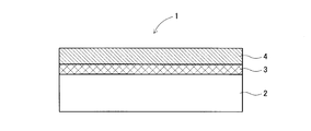
- the infrared reflecting substrate 1 is formed on the upper surface of the transparent substrate 2 and is supported on the transparent substrate 2 from the back surface side, and red.
- the outer reflection layer 3 is formed on the upper surface (surface) and is composed of a protective layer 4 made of a polycycloolefin layer.
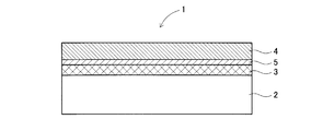
- the infrared reflecting substrate 1 is formed on the upper surface of the transparent substrate 2 and supported on the transparent substrate 2 from the back side.
- a protective layer 4 made of a polycycloolefin layer which is attached to the upper surface (surface) of the infrared reflective layer 3 through the transparent adhesive layer 5.
- the protective layer 4 made of a polycycloolefin layer is directly formed on the infrared reflecting layer 3.
- the thickness of the polycycloolefin layer is 10 ⁇ m or less, it can be directly applied and formed on the infrared reflective layer 3.
- the protective layer 4 which consists of a polycycloolefin layer is adhere
- the thickness of the transparent adhesive layer 5 is 1 micrometer. It is desirable to prepare as follows.
- substrate 1 comprised as shown in FIG.1 and FIG.2, an emissivity can be suppressed low.
- you may have another layer, for example, an adhesive layer, in the back surface side of an infrared reflective layer.
- the visible light transmitting glazing according to JIS A-5759-2008 (architectural window glass film) of the infrared reflecting substrate is preferably 50% or more, more preferably 70% to 94%.
- the vertical emissivity of the infrared reflecting substrate in accordance with JISJR 3106-2008 is preferably 0.4 or less, more preferably It is 0.2 or less, more preferably 0.01 to 0.15.
- the infrared reflective layer used in the infrared reflective substrate according to the present embodiment transmits visible light and reflects infrared light.
- the visible light transmittance according to JIS A 5759-2008 of the infrared reflection layer alone is preferably 50% or more, and the vertical emissivity according to JlS R 3106-2008 is preferably 0.1 or less. .
- the infrared reflection layer is usually formed by laminating a metal thin film such as gold or silver and a high refractive index thin film such as titanium dioxide or zirconium dioxide.
- a metal thin film such as gold or silver
- a high refractive index thin film such as titanium dioxide or zirconium dioxide.
- the material for forming the metal thin film for example, gold, silver, copper, or an alloy thereof is used.
- the thickness of the metal thin film can be adjusted preferably in the range of 5 nm to 1000 nm so that both the visible light transmittance and the infrared reflectance are increased.
- the high refractive index film preferably has a refraction index of 1.8 to 2.7.
- Materials for forming the high refractive index thin film are indium tin oxide, TiO 2 , ZrO 2 , SnO 2. In 2 O 3 or the like is used.
- the thickness of the high refractive index thin film can be adjusted preferably in the range of 20 nm to 80 nm.
- Examples of methods for forming the metal thin film and the high refractive index thin film include sputtering, vacuum deposition, and plasma CVD.
- the protective layer used for the infrared reflective substrate according to the present embodiment is composed of a polycycloolefin layer.
- polycycloolefin refers to a polymer or copolymer obtained using an alicyclic compound having a double bond.
- the polycycloolefin is preferably polynorbornene. This is because polynorbornene has little absorption in the infrared region and is excellent in weather resistance and heat insulation.
- commercially available products such as ZEONEX (registered trademark) and ZEONOR (registered trademark) manufactured by Nippon Zeon may be used.
- the polycycloolefin layer has a feature that absorption in the far infrared region is small because the basic structure is composed of carbon atoms and hydrogen atoms. Accordingly, by appropriately adjusting the thickness, for example, the minimum transmittance in the wavelength range of 5 ⁇ m to 25 ⁇ m (far infrared region) can be increased (for example, 50% or more).
- the thickness of the polycycloolefin layer is preferably 0.5 ⁇ m to 100 ⁇ m, more preferably 1 ⁇ m to 50 ⁇ m, and particularly preferably 1 ⁇ m to 10 ⁇ m. If the said thickness is 10 micrometers or less, since the polycycloolefin layer is apply
- the polycycloolefin layer may contain additives such as an antioxidant and an antistatic agent in addition to the polycycloolefin.
- additives such as an antioxidant and an antistatic agent in addition to the polycycloolefin.
- Examples of the method for forming the polycycloolefin layer include a melt extrusion method and a solution casting method.
- the transparent substrate used for the infrared reflective substrate according to the present embodiment has a visible light transmittance of 80% or more.
- the thickness of the transparent substrate is not particularly limited, but is, for example, 10 ⁇ m to 150 ⁇ m.
- the material forming the transparent substrate is a glass plate or a polymer film. Since the molding temperature of the infrared reflective layer is often high, when a polymer film is used as the transparent substrate, a material excellent in heat resistance is preferably used.
- the polymer film include polyethylene terephthalate, polyethylene naphthalate, polyether ether ketone, and polycarbonate.
- the use of the infrared reflective substrate of the present invention is not particularly limited.
- the infrared reflective substrate is attached to a window for a building or a vehicle, a transparent case for storing plants, a frozen or refrigerated showcase, It is preferably used in order to improve the effect and prevent a rapid temperature change.
- Example 1 A polyethylene terephthalate film (trade name “Diafoil U300E125” manufactured by Mitsubishi Plastics, Inc.) having a thickness of 125 ⁇ m is coated with a SIO X film having a thickness of 50 nm and an indium tin oxide having a thickness of 35 nm (hereinafter referred to as ITO) by DC magnetron sputtering. Film, thickness 13nm An Ag—Au alloy (Au 3 Wt%) film, an ITO film with a thickness of 35 nm, and a SIO X film with a thickness of 200 nm were sequentially laminated to form an infrared reflective layer.
- ITO indium tin oxide having a thickness of 35 nm
- Example 2 An infrared reflective substrate was produced in the same manner as in Example 1 except that a 8.5 ⁇ m thick polynorbornene layer was used as the protective layer. Table 1 shows the vertical emissivity of the obtained infrared reflecting substrate and the results of the weather resistance test.
- Example 3 As a conservative layer, a 23 ⁇ m thick polynorbornene film (trade name “ZEONOR” manufactured by Nippon Zeon Co., Ltd.) is used, and this is applied to the surface of the infrared reflective layer via a 80 nm (nanometer) thickness poly-engineered steal adhesive.
- An infrared reflective substrate was produced in the same manner as in Example 1 except that it was attached. Table 1 shows the vertical emissivity of the obtained infrared reflecting substrate and the results of the weather resistance test.
- Example 4 As a protective layer, a polynorbornene film with a thickness of 40 ⁇ m (trade name “ZEONOR” manufactured by Nippon Zeon Co., Ltd.) was used, and this was carried out except that it was attached to the surface of the infrared reflecting layer via a polyester adhesive with a thickness of 80 nm.
- An infrared reflective substrate was produced in the same manner as in Example 1. Table 1 shows the vertical emissivity of the obtained infrared reflecting substrate and the results of the weather resistance test.
- a polyethylene terephthalate film having a thickness of 23 ⁇ m (trade name “Diafoil T609E25” manufactured by Mitsubishi Chemical Polyester Co., Ltd.) was used, and this was adhered to the surface of the infrared reflective layer with a polyester adhesive having a thickness of 80 nm.
- a polyester adhesive having a thickness of 80 nm.
- Table 1 shows the vertical emissivity of the obtained infrared reflecting substrate and the results of the weather resistance test.
- a hard coat layer having a thickness of 4.9 ⁇ m (trade name “acrylic-urethane hard coat PC1097” manufactured by DIC Co., Ltd.) was applied to the surface of the infrared reflective layer and cured with ultraviolet rays) was used.
- An infrared reflective substrate was produced in the same manner as in Example 1. Table 1 shows the vertical emissivity of the obtained infrared reflecting substrate and the results of the weather resistance test.
- Example 4 An infrared reflective substrate was produced in the same manner as in Example 1 except that the protective layer was not used (the infrared reflective layer was used in an exposed state). Table 1 shows the vertical emissivity of the obtained infrared reflecting substrate and the results of the weather resistance test.
- the infrared reflective substrate using a polycycloolefin layer having a thickness of 20 ⁇ m or less as the protective layer has a vertical emissivity of 0.2 or less and excellent heat insulation.
- the thickness of the polynorbornene layer is 10 ⁇ m or less
- the heat insulation is particularly excellent (Examples 1 and 2).
- Comparative Example 1 when a polyethylene terephthalate film is used as the protective layer, the vertical emissivity is twice or more that of the polycycloolefin layer.
- Comparative Examples 2 and 3 when a hard coat agent is used as the protective layer, the result is the same as that of Comparative Example 1 (high vertical emissivity).
- the protective layer is not used as in Comparative Example 4, the infrared reflective substrate cannot be used outdoors because the weather resistance of the infrared reflective layer is poor.
- the present invention it is possible to suppress the emissivity by forming the protective layer of the infrared reflective layer from a polycycloolefin layer, and thus it is possible to provide an infrared reflective substrate excellent in heat resistance and weather resistance. .
Landscapes
- Physics & Mathematics (AREA)
- General Physics & Mathematics (AREA)
- Optics & Photonics (AREA)
- Laminated Bodies (AREA)
- Optical Filters (AREA)
Abstract
Description
このような赤外線反射積層体は、建物、乗物等の窓に貼着されて冷暖房効果を向上させたり、また、冷凍冷蔵ショーケースの窓に貼着されて保冷効果を向上させたりする用途に使用されている。
ここに、前記積層体の保護フィルムは、通常、ポリエチレンテレフタレートフィルムやアクリル系UVハードコート剤等から形成され、赤外線反射層に耐擦傷性や耐候性を付与するために用いられる。
また、前記保護層は、請求項5に記載されているように、ポリノルボルネン層から形成されていることが望ましい。
更に、前記赤外線反射基板の垂直放射率は、請求項6に記載されているように、0.1以下であることが望ましい。
尚、前記保護層は、請求項7に記載されているように、1μm以下の透明な接着剤層を介して前記透明基板に接着されていても良い。
2 透明基板
3 赤外線反射層
4 保護層
5 接着剤層
本実施形態の赤外線反射基板は、赤外線反射層と、赤外線反射層の表面に設けられた保譲層と、赤外線反射層を裏面側から支持する透明基板とを有する赤外線反射基板であって、保護層が、ポリシクロオレフィン層からなるものである。
また、本実施形態の他の例としては、図2に示すように、赤外線反射基板1は、透明基板2の上面に形成されて透明基板2上にて裏面側から支持される赤外線反射層3、及び、透明接着剤層5を介して赤外反射層3の上面(表面)に貼着され、ポリシクロオレフィン層からなる保護層4とから構成されている。
また、図2に示す例では、透明接着剤層5を介して赤外線反射層3の上面にポリシクロオレフィン層からなる保護層4を接着しているが、透明接着剤層5の厚みは、1μm以下に調製することが望ましい。
図1及び図2に示すように構成された赤外線反射基板1であれば、放射率を低く抑制することができる。
尚、上記赤外線反射基板1では、赤外線反射層の裏面側に他の層、例えば、接着層を有していても良い。
本実施形態に係る赤外線反射基板に用いられる赤外線反射層は、可視光を透過し、赤外線を反射するものである。上記赤外線反射層単体の、JIS A 5759-2008に準じた可視光線透過率は、好ましくは50%以上であり、JlS R 3106-2008に準じた垂直放射率は、好ましくは0.1以下である。
上記金属薄膜を形成する材料は、例えば、金、銀、銅又はそれらの合金等が用いられる。上記金属薄膜の厚みは、可視光線透過率と赤外線反射率が共に高くなるように、好ましくは5nm~1000nmの範囲で、調整され得る。
上記高屈折率簿膜は、好ましくは1.8~2.7の転囲の屈折率を有するものである。上記高屈折率薄膜を形成する材料は、インジウム錫酸化物,TiO2,ZrO2,SnO2
,In2O3等が用いられる。上記高屈折率薄膜の厚みは、好ましくは20nm~80nmの範囲で、調整され得る。
上記の金属薄膜及び高屈折率薄膜の成形方法としては、例えば、スパッタ法や真空蒸着法、プラズマCVD法等が挙げられる。
本実施形態に係る赤外線反射基板に用いられる保護層は、ポリシクロオレフィン層からなる。本明細書において「ポリシクロオレフィン」とは、二重結合を有する脂環式化合物を用いて得られる重合体又は共重合体をいう。上記ポリシクロオレフィンは、好ましくはポリノルボルネンである。ポリノルボルネンは、赤外領域の吸収が少なく、且つ耐候性と断熱性に優れるからである。これらのポリマーとしては、日本ゼオン社製のZEONEX(商標登録)やZEONOR(商標登録)等市販のものを用いてもよい。
上記ポリシクロオレフィン層は、基本構造が、炭素原子と水素原子から構成されるため、遠赤外領域の吸収が小さいという特徴を有する。従って、厚みを適宜調整することにより、例えば、波長5μm~25μmの範囲(遠赤外領域)の最小透過率を高く(例えば、50%以上)することができる。
上記ポリシクロオレフィン層の厚みが100μmを超えると、赤外領域の吸収が無視できなくなり、断熱性が低下する虞がある。一方、上記ポリシクロオレフィン層の厚みが0.5μm未満であると、赤外線反射層の金属膜に劣化が生じて、耐候性が低下する虞がある。
上記ポリシクロオレフィン層の成形方法としては、例えば、溶融押出法や溶液キャスト法等が挙げられる。
本実施形態に係る赤外線反射基板に用いられる透明基板は、可視光線透過率が80%以上あるものである。上記透明基板の厚みは、特に制限はないが、例えば10μm~150μmである。
上記透明基板を形成する材料は、ガラス板やポリマーフィルムである。上記赤外線反射層の成形温度が高くなる場合が多いため、透明基板としてポリマーフィルムを用いる場合は、耐熱性に優れたものが好ましく使用される。
上記ポリマーフィルムは、例えば、ポリエチレンテレフタレート、ポリエチレンナフタレート、ポリエーテルエ-テルケトン、ポリカーボネート等である。
本発明の赤外線反射基板の用途は、特に制限はないが、例えば、上記赤外線反射基板は、建物や乗り物等の窓、植物等を入れる透明ケース、冷凍もしくは冷蔵のショーケースに貼着し、冷暖房効果の向上や急激な温度変化を防ぐために、好ましく使用される。
[実施例1]
厚さ125μmのポリエチレンテレフタレートフィルム(三菱樹脂社製 商品名「ダイアホイル U300E125」)に、DCマグネトロンスパッタ法により、厚さ50nmのSIOX膜と、厚さ35nmのインジウム錫酸化物(以下、ITO)膜、厚さ13nm
のAg-Au合金(Au3Wt%)膜、厚さ35nmのITO膜、厚さ200nmのSIOX膜を順次積層し、赤外線反射層を形成した。
この赤外線反射層の表面に、シクロオクタンに溶解したポリノルボルネン(日本ゼオン社製 商品名「ZEONOR」)溶液を塗布し、乾操して厚み5.1μmのポリノルボルネン層からなる保護層を形成した。このように作製した赤外線反射基板(総厚み約130.4μm、可視光線透過率78%)の垂直放射率と耐候性試験の結果を表1に示す。
保護層として、厚み8.5μmのポリノルボルネン層を用いた以外は、実施例1と同様の方法で、赤外線反射基板を作製した.得られた赤外線反射基板の垂直放射率と耐候性試験の結果を表1に示す。
保譲層として、厚み23μmのポリノルボルネンフィルム(日本ゼオン社製 商品名「ZEONOR」)を用い、これを赤外線反射層の表面に、厚み80nm(ナノメートル)のポリ工ステル系接着剤を介して貼着した以外は、実施例1と同様の方法で、赤外線反射基板を作製した。得られた赤外線反射基板の垂直放射率と耐候性試験の結果を表1に示す。
保護層として、厚み40μmのポリノルボルネンフィルム(日本ゼオン社製 商品名「ZEONOR」)を用い、これを赤外線反射層の表面に、厚み80nmのポリエステル系接着剤を介して貼着した以外は、実施例1と同様の方法で、赤外線反射基板を作製した。得られた赤外線反射基板の垂直放射率と耐候性試験の結果を表1に示す。
保護層として、厚み23μmのポリエチレンテレフタレートフィルム(三菱化学ポリエステル社製 商品名「ダイアホイル T609E25」)を用い、これを赤外線反射層の表面に、厚み80nmのポリエステル系接着剤を介して貼着した以外は、実施例1と同様の方法で、赤外線反射基板を作製した。
得られた赤外線反射基板の垂直放射率と耐候性試験の結果を表1に示す。
保護層として、厚み4.9μmのハードコート層(DIC社製 商品名「アクリル-ウレタン系ハードコートPC1097」)を赤外線反射層の表面に塗布し、紫外線硬化させたもの)を用いた以外は、実施例1と同様の方法で、赤外線反射基板を作製した。得られた赤外線反射基板の垂直放射率と耐候性試験の結果を表1に示す。
保護層として、厚み6.1μmのハードコート層(JSR社製 商品名「有機-無機ハイブリッド系ハードコートオプスターZ7540」を赤外線反射層の表面に塗布し、紫外線硬化させたもの)を用いた以外は、実施例1と同様の方法で、赤外線反射基板を作製した。得られた赤外線反射基板の垂直放射率と耐候性試験の結果を表1に示す。
保護層を用いなかった(赤外線反射層を露出した状態で用いた)こと以外は、実施例1と同様の方法で、赤外線反射基板を作製した。得られた赤外線反射基板の垂直放射率と耐候性試験の結果を表1に示す。

PNB=ポリノルボルネン
PET=ポリエチレンテレフタレート
HC剤=ハードコート剤
実施例1~4に示すように、保護層として厚みが20μm以下のポリシクロオレフィン層を用いた赤外線反射基板は、垂直放射率が0.2以下であり、断熱性に優れることが分かる。特に、ポリノルボルネン層の厚みが10μm以下である場合、断熱性に特に優れる(実施例1及び2)。
比較例1に示すように、保護層としてポリエチレンテレフタレートフィルムを用いた場合、垂直放射率はポリシクロオレフィン層の2倍以上高い。比較例2及び3に示すように、保護層としてハードコート剤を用いた場合も、比較例1と同様の結果である(垂直放射率が高い)。
比較例4のように保護層を用いない場合は、赤外線反射層の耐候性が乏しいため、赤外線反射基板を屋外で使用することができない。
[厚みの測定方法]
厚み10μm以下の保護層については、保護層の一部を剥離し、触針式表面形状測定器(Veeco社製 製品名「Dektak」)を用いて、段差を計測して求めた。厚み10μmを超える保譲層については、デジタルマイクロメーター(ミツトヨ社製)で求めた。
角度可変反射アクセサリを装着したフーリエ変換型赤外分光(FT-1R)装置(Varian社製)を用いて、波長5ミクロン~25ミクロンの赤外光の正反射率を測定し、JIS R 3106-2008(板ガラス類の透過率・反射率・放射率・日射熱取得率の試験方法)に準じて求めた。
キセノンウェザーメーター(スガ試験機社製 製品名「X25」)を用いて、下記条件1及び条件2を1サイクルとして、100サイクル繰り返した。その後、赤外線反射基板の状態を目視観察し、赤外線反射層の劣化が認められないものを○、劣化(銀のマイグレーション)が認められるものを×として評価した。
<条件1(照射+降雨)>
時間:12分間、照度:48W/m2、温度:38℃、湿度:95%RH
<条件2(照射)>
時間:48分間、照度:48W/m2、温度:63℃、湿度:50%RH
分光光度計(日立ハイテク社製 製品名「U-4100」)を用いて、JIS A 5759-2008(建築窓ガラスフィルム)に準じて求めた。
Claims (7)
- 赤外線反射層と、
前記赤外線反射層の表面に設けられた保護層と、
前記赤外線反射層を裏面側から支持する透明基板とを有する赤外線反射基板であって、
前記保護層は、ポリシクロオレフィン層からなることを特徴とする赤外線反射基板。 - 前記保護層の厚みは、0.5μm~100μmの範囲にあることを特徴とする請求項1に記載の赤外線反射基板。
- 前記保護膜の厚みは、1μm~50μmの範囲にあることを特徴とする請求項2に記載の赤外線反射基板。
- 前記保護層の厚みは、1μm~10μmの範囲にあることを特徴とする請求項3に記載の赤外線反射基板。
- 前記保護層は、ポリノルボルネン層から形成されていることを特徴とする請求項1乃至請求項4のいずれかに記載の赤外線反射基板。
- 前記赤外線反射基板の垂直放射率は、0.4以下であることを特徴とする請求項1に記載の赤外線反射基板。
- 前記保護層は、1μm以下の透明な接着剤層を介して前記透明基板に接着されていることを特徴とする請求項1乃至請求項6いずれかに記載の赤外線反射基板。
Priority Applications (3)
| Application Number | Priority Date | Filing Date | Title |
|---|---|---|---|
| CN201080052126.3A CN102667545B (zh) | 2009-11-18 | 2010-11-09 | 红外线反射基板 |
| KR1020127015507A KR101370763B1 (ko) | 2009-11-18 | 2010-11-09 | 적외선 반사 기판 |
| US13/497,402 US20120268810A1 (en) | 2009-11-18 | 2010-11-09 | Infrared ray reflective substrate |
Applications Claiming Priority (2)
| Application Number | Priority Date | Filing Date | Title |
|---|---|---|---|
| JP2009262825A JP5389616B2 (ja) | 2009-11-18 | 2009-11-18 | 赤外線反射基板 |
| JP2009-262825 | 2009-11-18 |
Publications (1)
| Publication Number | Publication Date |
|---|---|
| WO2011062084A1 true WO2011062084A1 (ja) | 2011-05-26 |
Family
ID=44059563
Family Applications (1)
| Application Number | Title | Priority Date | Filing Date |
|---|---|---|---|
| PCT/JP2010/069897 Ceased WO2011062084A1 (ja) | 2009-11-18 | 2010-11-09 | 赤外線反射基板 |
Country Status (6)
| Country | Link |
|---|---|
| US (1) | US20120268810A1 (ja) |
| JP (1) | JP5389616B2 (ja) |
| KR (1) | KR101370763B1 (ja) |
| CN (1) | CN102667545B (ja) |
| TW (1) | TWI434764B (ja) |
| WO (1) | WO2011062084A1 (ja) |
Cited By (3)
| Publication number | Priority date | Publication date | Assignee | Title |
|---|---|---|---|---|
| US20150022879A1 (en) * | 2012-01-30 | 2015-01-22 | Nitto Denko Corporation | Infrared reflective film |
| EP2902190A4 (en) * | 2012-09-28 | 2015-11-11 | Sumitomo Riko Co Ltd | TRANSPARENT MULTILAYER FILM |
| EP2881769A4 (en) * | 2012-08-06 | 2016-03-09 | Konica Minolta Inc | LIGHT REFLECTIVE FILM AND LIGHT REFLECTOR MADE THEREFROM |
Families Citing this family (11)
| Publication number | Priority date | Publication date | Assignee | Title |
|---|---|---|---|---|
| JP5868084B2 (ja) | 2011-09-12 | 2016-02-24 | 日東電工株式会社 | 赤外線反射フィルム |
| JP5762272B2 (ja) * | 2011-12-21 | 2015-08-12 | 河西工業株式会社 | 車両用天井材 |
| MX336599B (es) | 2011-12-21 | 2016-01-21 | Kasai Kogyo Kk | Material interior para vehiculos. |
| WO2013122227A1 (ja) * | 2012-02-16 | 2013-08-22 | 日東電工株式会社 | 赤外線反射基板の製造方法 |
| JP5859476B2 (ja) * | 2013-04-11 | 2016-02-10 | 日東電工株式会社 | 赤外線反射フィルム |
| JP6235939B2 (ja) * | 2014-03-13 | 2017-11-22 | マクセルホールディングス株式会社 | 透明遮熱断熱部材 |
| TWI566444B (zh) * | 2014-07-10 | 2017-01-11 | 遠東科技大學 | 反射式輻射散熱之基板及發光件 |
| JP6301483B2 (ja) * | 2014-08-27 | 2018-03-28 | 富士フイルム株式会社 | 断熱フィルム、断熱フィルムの製造方法、断熱ガラスおよび窓 |
| JP2017031322A (ja) * | 2015-07-31 | 2017-02-09 | 富士フイルム株式会社 | 断熱塗料 |
| CN106011750A (zh) * | 2016-07-11 | 2016-10-12 | 中国科学院上海技术物理研究所 | 一种耐紫外辐照的银金合金薄膜及制备方法 |
| JP6940423B2 (ja) * | 2018-01-29 | 2021-09-29 | リンテック株式会社 | 赤外線反射フィルムおよび赤外線反射フィルムの被着体への貼付方法 |
Citations (4)
| Publication number | Priority date | Publication date | Assignee | Title |
|---|---|---|---|---|
| JPH11339520A (ja) * | 1998-05-29 | 1999-12-10 | Nippon Zeon Co Ltd | 灯具およびランプカバー |
| JP2000117919A (ja) * | 1998-10-16 | 2000-04-25 | Teijin Ltd | 高透明熱線反射フィルム |
| JP2005338395A (ja) * | 2004-05-26 | 2005-12-08 | Jsr Corp | 近赤外線カットフィルターおよびその製造方法 |
| JP2009221415A (ja) * | 2008-03-18 | 2009-10-01 | Panasonic Corp | 赤外光学素子用材料及びこれを用いた赤外光学素子 |
Family Cites Families (11)
| Publication number | Priority date | Publication date | Assignee | Title |
|---|---|---|---|---|
| DE3039821A1 (de) * | 1980-10-22 | 1982-06-03 | Robert Bosch Gmbh, 7000 Stuttgart | Mehrschichtsystem fuer waermeschutzanwendung |
| US4716086A (en) * | 1984-12-19 | 1987-12-29 | Ppg Industries, Inc. | Protective overcoat for low emissivity coated article |
| CA2041038C (en) * | 1990-05-10 | 2001-01-02 | Jesse D. Wolfe | Durable low-emissivity thin film interference filter |
| US6049419A (en) * | 1998-01-13 | 2000-04-11 | 3M Innovative Properties Co | Multilayer infrared reflecting optical body |
| US6911507B2 (en) * | 2001-01-24 | 2005-06-28 | Jsr Corporation | Processes for producing cycloolefin addition polymer |
| JP2002323860A (ja) * | 2001-04-25 | 2002-11-08 | Mitsui Chemicals Inc | ディスプレイ用光学フィルタならびにこれを用いた表示装置およびディスプレイ用保護板 |
| JP2006301182A (ja) * | 2005-04-19 | 2006-11-02 | Kureha Corp | 光学フィルターおよびその製造方法並びに撮像装置 |
| EP1880578A1 (en) * | 2005-05-11 | 2008-01-23 | NV Bekaert SA | A reflector for an infrared radiating element |
| CN101288007A (zh) * | 2005-10-26 | 2008-10-15 | 中央硝子株式会社 | 近红外线反射基板和利用该基板的近红外线反射层叠玻璃、近红外线反射双层玻璃 |
| KR100908184B1 (ko) * | 2006-07-31 | 2009-07-16 | 주식회사 엘지화학 | 편광판 및 이를 이용한 액정표시장치 |
| US8445098B2 (en) * | 2008-03-11 | 2013-05-21 | Ppg Industries Ohio, Inc. | Reflective article having multiple reflective coatings |
-
2009
- 2009-11-18 JP JP2009262825A patent/JP5389616B2/ja not_active Expired - Fee Related
-
2010
- 2010-11-09 CN CN201080052126.3A patent/CN102667545B/zh not_active Expired - Fee Related
- 2010-11-09 WO PCT/JP2010/069897 patent/WO2011062084A1/ja not_active Ceased
- 2010-11-09 KR KR1020127015507A patent/KR101370763B1/ko not_active Expired - Fee Related
- 2010-11-09 US US13/497,402 patent/US20120268810A1/en not_active Abandoned
- 2010-11-16 TW TW099139338A patent/TWI434764B/zh not_active IP Right Cessation
Patent Citations (4)
| Publication number | Priority date | Publication date | Assignee | Title |
|---|---|---|---|---|
| JPH11339520A (ja) * | 1998-05-29 | 1999-12-10 | Nippon Zeon Co Ltd | 灯具およびランプカバー |
| JP2000117919A (ja) * | 1998-10-16 | 2000-04-25 | Teijin Ltd | 高透明熱線反射フィルム |
| JP2005338395A (ja) * | 2004-05-26 | 2005-12-08 | Jsr Corp | 近赤外線カットフィルターおよびその製造方法 |
| JP2009221415A (ja) * | 2008-03-18 | 2009-10-01 | Panasonic Corp | 赤外光学素子用材料及びこれを用いた赤外光学素子 |
Cited By (3)
| Publication number | Priority date | Publication date | Assignee | Title |
|---|---|---|---|---|
| US20150022879A1 (en) * | 2012-01-30 | 2015-01-22 | Nitto Denko Corporation | Infrared reflective film |
| EP2881769A4 (en) * | 2012-08-06 | 2016-03-09 | Konica Minolta Inc | LIGHT REFLECTIVE FILM AND LIGHT REFLECTOR MADE THEREFROM |
| EP2902190A4 (en) * | 2012-09-28 | 2015-11-11 | Sumitomo Riko Co Ltd | TRANSPARENT MULTILAYER FILM |
Also Published As
| Publication number | Publication date |
|---|---|
| KR20120094041A (ko) | 2012-08-23 |
| TW201125728A (en) | 2011-08-01 |
| JP5389616B2 (ja) | 2014-01-15 |
| CN102667545B (zh) | 2015-05-27 |
| TWI434764B (zh) | 2014-04-21 |
| KR101370763B1 (ko) | 2014-03-06 |
| US20120268810A1 (en) | 2012-10-25 |
| JP2011104887A (ja) | 2011-06-02 |
| CN102667545A (zh) | 2012-09-12 |
Similar Documents
| Publication | Publication Date | Title |
|---|---|---|
| JP5389616B2 (ja) | 赤外線反射基板 | |
| JP6346952B2 (ja) | 改良された光対太陽利得熱比を示す光学膜 | |
| JP2011509193A5 (ja) | ||
| JP5959746B2 (ja) | 光透過性積層体 | |
| CN1122128A (zh) | 玻璃的涂层 | |
| JP2017053967A (ja) | 透明遮熱断熱部材及びその製造方法 | |
| JP6629340B2 (ja) | 窓用フィルムとその製造方法 | |
| TW201524767A (zh) | 具有優異的光學和太陽能性能的複合膜 | |
| JP3901911B2 (ja) | 透明積層フィルム | |
| CN108369368A (zh) | 反射型透明屏幕 | |
| JPWO2016117436A1 (ja) | 多層積層基板 | |
| WO2022019243A1 (ja) | 反射防止膜付透明基体および画像表示装置 | |
| CN110462463A (zh) | 热射线透射抑制透光性基材、透光性基材单元 | |
| JP2001174603A (ja) | ノルボルネン系樹脂成形品およびその製造方法 | |
| US20080032113A1 (en) | Glazing and Film Functional Coatings Having a Porous Inorganic Layer and a Polymeric Filler | |
| CN116075418A (zh) | 光学层叠体、物品 | |
| JP2882725B2 (ja) | 紫外線吸収断熱ガラス | |
| JP2023053748A (ja) | 光学積層体、反射防止膜 | |
| CN110809724A (zh) | 红外线反射基板 | |
| JP4404350B2 (ja) | 積層体 | |
| JP2014176995A (ja) | 透明遮熱断熱部材 | |
| WO2015098767A1 (ja) | 光学反射フィルム | |
| JP2015134456A (ja) | 積層フィルムおよび該フィルムを用いた窓ガラス | |
| KR102282176B1 (ko) | 저방사 필름 및 이를 포함하는 창문 | |
| JP6546461B2 (ja) | 透明断熱材料及びその製造方法 |
Legal Events
| Date | Code | Title | Description |
|---|---|---|---|
| WWE | Wipo information: entry into national phase |
Ref document number: 201080052126.3 Country of ref document: CN |
|
| 121 | Ep: the epo has been informed by wipo that ep was designated in this application |
Ref document number: 10831479 Country of ref document: EP Kind code of ref document: A1 |
|
| WWE | Wipo information: entry into national phase |
Ref document number: 13497402 Country of ref document: US |
|
| NENP | Non-entry into the national phase |
Ref country code: DE |
|
| ENP | Entry into the national phase |
Ref document number: 20127015507 Country of ref document: KR Kind code of ref document: A |
|
| 122 | Ep: pct application non-entry in european phase |
Ref document number: 10831479 Country of ref document: EP Kind code of ref document: A1 |