WO2011040522A1 - Seringue pré-remplie - Google Patents
Seringue pré-remplie Download PDFInfo
- Publication number
- WO2011040522A1 WO2011040522A1 PCT/JP2010/067076 JP2010067076W WO2011040522A1 WO 2011040522 A1 WO2011040522 A1 WO 2011040522A1 JP 2010067076 W JP2010067076 W JP 2010067076W WO 2011040522 A1 WO2011040522 A1 WO 2011040522A1
- Authority
- WO
- WIPO (PCT)
- Prior art keywords
- plunger
- mounting member
- gasket
- rib
- plunger mounting
- Prior art date
Links
Images


Classifications
-
- A—HUMAN NECESSITIES
- A61—MEDICAL OR VETERINARY SCIENCE; HYGIENE
- A61M—DEVICES FOR INTRODUCING MEDIA INTO, OR ONTO, THE BODY; DEVICES FOR TRANSDUCING BODY MEDIA OR FOR TAKING MEDIA FROM THE BODY; DEVICES FOR PRODUCING OR ENDING SLEEP OR STUPOR
- A61M5/00—Devices for bringing media into the body in a subcutaneous, intra-vascular or intramuscular way; Accessories therefor, e.g. filling or cleaning devices, arm-rests
- A61M5/178—Syringes
- A61M5/31—Details
- A61M5/315—Pistons; Piston-rods; Guiding, blocking or restricting the movement of the rod or piston; Appliances on the rod for facilitating dosing ; Dosing mechanisms
- A61M5/31511—Piston or piston-rod constructions, e.g. connection of piston with piston-rod
- A61M5/31515—Connection of piston with piston rod
-
- A—HUMAN NECESSITIES
- A61—MEDICAL OR VETERINARY SCIENCE; HYGIENE
- A61M—DEVICES FOR INTRODUCING MEDIA INTO, OR ONTO, THE BODY; DEVICES FOR TRANSDUCING BODY MEDIA OR FOR TAKING MEDIA FROM THE BODY; DEVICES FOR PRODUCING OR ENDING SLEEP OR STUPOR
- A61M5/00—Devices for bringing media into the body in a subcutaneous, intra-vascular or intramuscular way; Accessories therefor, e.g. filling or cleaning devices, arm-rests
- A61M5/14—Infusion devices, e.g. infusing by gravity; Blood infusion; Accessories therefor
- A61M5/142—Pressure infusion, e.g. using pumps
- A61M5/145—Pressure infusion, e.g. using pumps using pressurised reservoirs, e.g. pressurised by means of pistons
- A61M5/1452—Pressure infusion, e.g. using pumps using pressurised reservoirs, e.g. pressurised by means of pistons pressurised by means of pistons
- A61M5/1458—Means for capture of the plunger flange
Definitions
- the present invention relates to a prefilled syringe prefilled with a chemical solution.
- the plunger When the plunger is already mounted, it is difficult to place the gasket in the opening of the outer cylinder, and thus the above-described plugging operation is performed with the gasket alone. For this reason, as a prefilled syringe, it is common to require a subsequent plunger mounting operation. And in order to make the plunger mounting work to the gasket easy, and to prevent the occurrence of liquid leakage during the mounting work and to suppress the increase in internal pressure, the plunger is provided with a male thread part, and the gasket is provided with a female thread part. What has the mounting mechanism by both screwing is common.
- the syringe and the prefilled syringe may be administered by being attached to a syringe pump.
- a syringe pump When a syringe pump is used, a minute amount of continuous administration is performed.
- the syringe pump is located higher than the patient, there is a possibility that a drug solution may be rapidly administered due to a drop. That is, in such a state, the drop causes the inside of the syringe to be in a negative pressure state, the gasket is sucked forward of the outer cylinder, and the pressing means of the syringe pump fixed to the plunger moves the gasket along with the suction. It is intended to administer a minute amount of continuous administration while preventing this.
- the negative pressure overcomes the engagement force between the plunger and the gasket, there is a risk that the gasket will be detached from the plunger, and when the gasket is detached, the medicine in the syringe is rapidly administered.
- Patent Document 1 Japanese Patent Application Laid-Open No. 2002-272843
- Patent Document 2 Japanese Patent Application Laid-Open No. 2009-142508
- Patent Document 3 Japanese Patent Application Laid-Open No. 2009-142508
- Patent Document 4 Patent Documents 1 to 3 are proposals of the applicant of the present application.
- a gasket having a gasket body and a plunger mounting member has been proposed.
- Patent Document 5 Japanese Utility Model Publication No. 6-39005
- Patent Document 6 Japanese Patent Application Laid-Open No. 2007-44159
- Patent Document 7 Japanese Laid-Open Patent Publication No. 2008-307237
- Patent Document 8 Japanese Patent No. 3665646
- Patent Document 1 Japanese Patent Laid-Open No. 2002-272843
- Japanese Patent Laid-Open No. 2002-272843 Japanese Patent Laid-Open No. 2002-272843
- a plunger 4 to be operated.
- a liquid 7 is stored in advance in a liquid-tight manner.
- a flange portion 44 is formed on the head portion 43 at the distal end portion of the plunger 4.
- the gasket 3 has a hollow portion 33, and a screw thread 34 is formed on the inner surface on the proximal end side.
- a space 35 in which the flange 44 is accommodated is formed on the tip side of the thread 34.
- the flange 44 that has entered the space 35 beyond the thread 34 is engaged with the space 35 in a loosely fitted state.
- the flange 44 formed on the head 43 at the tip of the plunger 4 is not threaded, so it is attached to the syringe pump and, as described above, the syringe pump is higher than the patient.
- the plunger When administered at the position, the plunger may be detached from the gasket.
- a syringe 10 disclosed in Patent Document 2 includes a gasket 3, an outer cylinder 2, and a plunger 4.
- the plunger 4 includes a spiral rib 44 provided on the outer surface of the head portion 42, and the gasket includes a spiral screw portion 33 for screwing with the spiral rib, and the vicinity of the spiral screw portion 33.
- a plunger retaining annular rib 34 located on the distal end side and a helical rib forming portion storage portion 32 of the plunger head portion are provided.
- the annular rib 34 includes a rib deficient portion 35 for guiding the helical rib that has reached the annular rib to the storage portion by the progress of the screwing of the helical rib of the plunger and the helical screwing portion of the gasket. .
- This syringe is effective for preventing the plunger from coming off. However, depending on the manner in which the plunger is mounted, a mounting failure may rarely occur.
- a head portion (connecting portion) 43 that is inserted into the hollow portion 33 of the gasket 3 and connected to the gasket 3 is formed at the distal end portion of the plunger 4. ing.
- a male screw 51 is formed on the outer peripheral surface of the head portion 43.
- a female screw 52 that can be screwed with the male screw 51 is formed on the inner peripheral surface of the hollow portion 33 of the gasket 3.
- the head portion 43 includes an elastic piece 61 disposed on the distal end side from the male screw 51 and a protrusion 62 that is formed in the vicinity of the end portion of each elastic piece 61 so as to protrude in the outer peripheral direction.
- a ring-shaped engagement protrusion 63 is formed to protrude from the inner peripheral surface on the distal end side by the female screw 52 of the hollow portion 33 of the gasket 3.
- This syringe is also attached to the gasket by rotating the plunger, and a rotating operation is required for attaching the plunger.
- the screwing may not be performed properly. In this state, the gasket outer surface may not be a perfect circle, and liquid leakage may occur.
- the stress when the mounted plunger is inclined may be directly transmitted to the gasket, causing liquid leakage.
- the plunger used in the syringe of Patent Document 4 includes a plunger rod 22 and a gasket 21.
- the gasket 21 has an inner space with a closed end, and an inner space at the proximal end.
- the plunger rod 22 has a male screw-like protrusion 223 formed at the tip thereof and the protrusion 223 enters the inner space beyond the opening 212, the gasket 21 is formed.
- the plunger rod 22 are configured to engage in a loosely fitted state.
- the “small-diameter opening” of this syringe not only “not screw-like”, but also prevents it from falling off when the plunger is pulled in the proximal direction in addition to its function as a drop-off prevention rib due to reverse rotation. Because it is necessary, it is necessary to have higher strength. For this reason, when the screw is not properly screwed, the roundness of the outer surface of the gasket may be lowered and the liquid may leak when the female thread protrusion of the gasket is twisted and screwed.
- Patent Document 5 Japanese Utility Model Laid-Open No. 6-39005
- a synthetic resin reinforcing material 30 is fitted into an inner chamber of a rubber plunger 20 that is tightly fitted in the syringe 2 of the syringe serving as a container.
- This reinforcing member 30 reinforces the peripheral wall portion 23 that forms the inner chamber portion of the plunger 20.
- the plunger rod 10 is detachably attached to the reinforcing material 30.
- the insertion portion 16 of the plunger rod 10 is inserted from the insertion hole 34 (see FIG. 2) provided in the lid portion 32 of the reinforcing member 30, and the plunger rod 10 is rotated so that the blade plate 17 included in the insertion portion 16 of the plunger rod 10.
- the opposing rod 18 is fitted into a fitting groove 36 (see FIG. 3) on the back surface 32 of the lid portion 32 of the reinforcing member 30, whereby the plunger rod 10 to the plunger 20 into which the reinforcing member 30 is fitted. Installation is complete. With this syringe, during the mounting operation, the blade plate must be aligned with the slit-like fitting groove, and the plunger rod becomes in the way and cannot be visually observed. Therefore, the mounting operation is not easy. In addition, there is a risk that the plunger rod can be easily detached if the vane plate and the fitting groove are aligned after mounting.
- a syringe 1 of Patent Document 6 Japanese Patent Laid-Open No. 2007-44159
- the gasket 3 and the plunger 4 are connected by a connecting mechanism.
- the plunger 4 engages the upper plunger 41 and the lower plunger 42.
- the convex portion 422 provided on the plunger lower portion 42 is inserted into the concave portion 412 provided on the plunger upper portion 41, and when the insertion is completed, the convex portion 422 provided on the plunger lower portion 42 is The lower plunger 42 is rotated until it is located at the end.
- Patent Document 7 Japanese Patent Application Laid-Open No. 2008-307237
- Japanese Patent Application Laid-Open No. 2008-307237 is a prefilled syringe filled with a chemical solution and having a gasket plugged therein.
- a bottom rod connected from the base end side, a stopper formed on the coupler, and an engagement portion formed on the bottom rod that engages with the stopper by rotation of the bottom rod in a screwing direction,
- the stopper is elastically deformed and does not engage with the engaging portion when it comes into contact with the engaging portion from the anti-screwing direction. Also in this syringe, as in Patent Document 6, the mounting operation is not easy.
- Patent Document 8 Patent No. 3665646: WO95-30444
- the plunger rod is driven to move the shaft to the plunger.
- Directional tension is generated and the plunger diameter is reduced, and the reduction in the diameter reduces friction between the barrel interior and the plunger, while still maintaining the seal between the barrel interior and the plunger.
- the plunger rod includes a rod member and a coupling member of the plunger, and the rod member is slidable in the axial direction with respect to the coupling member.
- the plunger insertion portion 68 has a female screw 69 that engages with the male screw 71 of the plunger rod 50, and the plunger rod 50 is connected to the plunger insertion portion 68. It has a male screw 71 designed to engage a female screw 69.
- This syringe also requires a rotating operation for mounting the plunger.
- the syringe of the embodiment of FIGS. 7 to 18 includes a semi-circular plunger rod tip 164 having a convex surface protruding in the direction of the plunger, and this tip 164 is formed in a cross-shaped slit shown in FIG. It must be inserted and then rotated.
- the mounting of the plunger requires a positioning insertion operation into the slit of the tip 164 and a rotation operation. Moreover, as shown in FIG. 11, since the rod tip 164 contacts and deforms the plunger, there is a high possibility of liquid leakage. Also in this syringe, as in Patent Documents 6 and 7, the mounting operation is not easy, and there is a risk that the plunger rod may be detached after mounting.
- the object of the present invention is to confirm that the plunger is attached to the gasket during the plunger attaching operation to the gasket, and to reliably suppress the detachment of the gasket from the plunger after the attachment.
- a prefilled syringe that hardly deforms the gasket even when the plunger is tilted is provided.
- a gasket slidably housed in the outer cylinder, a sealing member for sealing a front end opening of the outer cylinder, and a medicine container formed in the outer cylinder
- a prefilled syringe comprising a prefilled syringe body made of a drug and a plunger that is attachable to the gasket and is in a non-attached state, wherein the gasket is a cylindrical body whose front end is closed and whose rear end is opened.
- a gasket body having a lumen extending from the rear end opening to the front end side, and a plunger mounting member attached to the gasket body, the plunger mounting member penetrating from one end to the other end.
- a plunger mounting portion for mounting the plunger formed in the base end portion of the base plate, and the gasket main body is provided on the inner surface of the lumen portion and is screwed with the spiral rib of the plunger mounting member.
- the plunger includes a pressing portion capable of pressing the proximal end surface of the proximal end flange portion of the plunger mounting member when the gasket is mounted, and protrudes to the distal end side from the pressing portion, Plunger mounting part A mounting tip that can enter the plunger mounting portion, and the plunger mounting portion of the plunger mounting member includes a spiral recess and an engagement rib provided near and on the tip side of the spiral recess.
- the mounting tip portion of the plunger is provided with a helical projection that can be screwed into the helical recess of the plunger mounting portion;
- An engagement portion that engages with the engagement rib of the attachment portion, and the plunger attachment member is attached to the gasket body in a state where the helical rib is accommodated in the accommodation portion, and the plunger
- the front end of the mounting member is not in contact with the inner surface of the gasket body, and the plunger is used for mounting the plunger when mounted on the gasket.
- a prefilled syringe whose tip is not in contact with the inner surface of the gasket body.
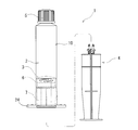
- FIG. 1 is a front view of a prefilled syringe according to an embodiment of the present invention.
- FIG. 2 is a longitudinal sectional view of a prefilled syringe body of the prefilled syringe shown in FIG.
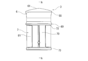
- FIG. 3 is an enlarged front view of a gasket used in the prefilled syringe of the present invention.
- 4 is a cross-sectional view taken along line AA in FIG.
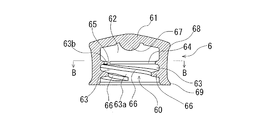
- FIG. 5 is a cross-sectional view of a gasket body used in the gasket shown in FIG. 6 is a cross-sectional view taken along line BB in FIG.
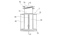
- FIG. 7 is a front view of a plunger mounting member used for the gasket shown in FIG.
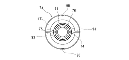
- FIG. 8 is a plan view of the plunger mounting member shown in FIG.
- FIG. 9 is a bottom view of the plunger mounting member shown in FIG. 10 is a cross-sectional view taken along the line CC of FIG.
- FIG. 11 is a perspective view of the plunger mounting member shown in FIG. 7 as viewed from the bottom side.
- FIG. 12 is an enlarged front view of a plunger used in the prefilled syringe of the present invention.
- FIG. 13 is a perspective view of the plunger of FIG.
- FIG. 14 is an enlarged plan view of the plunger shown in FIG.
- FIG. 15 is an enlarged front view of the distal end portion of the plunger shown in FIG.
- FIG. 16 is a perspective view of another example plunger used in the prefilled syringe of the present invention.
- FIG. 17 is a front view of an outer cylinder used in the prefilled syringe of the present invention.
- FIG. 18 is a cross-sectional view of a sealing member (seal cap) used in the prefilled syringe of the present invention.
- FIG. 19 is an explanatory diagram for explaining the operation when the prefilled syringe body and the plunger are mounted in the prefilled syringe of the present invention.
- FIG. 20 is an explanatory diagram for explaining the operation when the prefilled syringe body and the plunger are mounted in the prefilled syringe of the present invention.
- FIG. 21 is an explanatory diagram for explaining the operation when the prefilled syringe body and the plunger are mounted in the prefilled syringe of the present invention.
- FIG. 22 is a front view of a prefilled syringe according to another embodiment of the present invention.
- 23 is a longitudinal sectional view of the prefilled syringe body of the prefilled syringe shown in FIG. 24 is a front view of a plunger mounting member used in the gasket shown in FIG.
- FIG. 25 is a plan view of the plunger mounting member shown in FIG. 26 is a bottom view of the plunger mounting member shown in FIG. 27 is a cross-sectional view taken along the line DD of FIG.
- FIG. 28 is a perspective view of the plunger mounting member shown in FIG. FIG.
- FIG. 29 is an explanatory diagram for explaining the operation when the prefilled syringe body and the plunger are mounted in the prefilled syringe of the embodiment shown in FIGS. 22 and 23.
- FIG. 30 is an explanatory diagram for explaining the operation when the prefilled syringe main body and the plunger are mounted in the prefilled syringe of the embodiment shown in FIGS. 22 and 23.
- FIG. 31 is a perspective view of a plunger mounting member used in a prefilled syringe according to another embodiment of the present invention.
- 32 is a front view of the plunger mounting member shown in FIG.
- FIG. 33 is a perspective view of a plunger mounting member used in a prefilled syringe according to another embodiment of the present invention.
- FIG. 34 is a front view of the plunger mounting member shown in FIG.
- FIG. 35 is a perspective view of a plunger mounting member used in a prefilled syringe according to another embodiment of the present invention.
- FIG. 36 is a front view of the plunger mounting member shown in FIG.
- FIG. 37 is a perspective view of a plunger mounting member used in a prefilled syringe according to another embodiment of the present invention.
- FIG. 38 is a front view of the plunger mounting member shown in FIG.
- FIG. 39 is a perspective view of a plunger mounting member used in a prefilled syringe according to another embodiment of the present invention.
- FIG. 40 is a front view of the plunger mounting member shown in FIG. FIG.
- FIG. 41 is a perspective view of a plunger mounting member used in a prefilled syringe according to another embodiment of the present invention.
- 42 is a perspective view of the plunger mounting member shown in FIG. 41 viewed from the bottom surface side.
- 43 is a front view of the plunger mounting member shown in FIG. 44 is a right side view of the plunger mounting member shown in FIG. 43.
- FIG. FIG. 45 is a plan view of the plunger mounting member shown in FIG. 46 is a bottom view of the plunger mounting member shown in FIG. 43.
- FIG. 47 is a cross-sectional view taken along line EE of FIG.
- FIG. 48 is a partially enlarged view of FIG.
- FIG. 49 is a partially enlarged view of FIG.
- FIG. 50 is an explanatory diagram for explaining a mounting state of the gasket and the plunger mounting member in the prefilled syringe using the plunger mounting member shown in FIG. 43.
- the prefilled syringe 1 of the present invention includes an outer cylinder 2, a gasket 3 slidably accommodated in the outer cylinder 2, a sealing member 5 that seals the distal end opening of the outer cylinder 2, and an inner cylinder 2
- the prefilled syringe main body 10 which consists of the chemical
- the gasket 3 is a cylindrical body whose front end is closed and whose rear end is open, and which has a lumen body 60 extending from the rear end opening to the front end side, and a plunger attached to the gasket main body 6 And a member 7 for use.
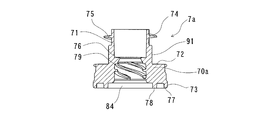
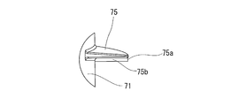
- the plunger mounting member 7 is a cylindrical body having a hollow portion penetrating from one end to the other end, a main body portion 70 having a front end side flange portion 72 capable of pressing the proximal end surface of the gasket main body 6 on the front end side, and a main body A front end portion 71 that protrudes forward from the portion 70 and can be stored in the inner cavity of the gasket main body 6, spiral ribs 74 and 75 provided on the outer surface of the front end portion 71, and a base end side of the main body portion 70.
- the base end side flange part 73 and the plunger mounting part for mounting the plunger formed in the base end part of the main-body part 70 are provided.
- the gasket body 6 is provided on the inner surface of the lumen portion, and has a helical thread portion 63 (63a, 63b) for screwing with the spiral ribs 74, 75 of the plunger mounting member 7, and a spiral portion of the lumen portion. And a storage portion 62 for storing the helical rib forming portion of the distal end portion 71 of the plunger mounting member 7 provided on the distal end side from the threaded engagement portion 63 (63a, 63b).
- the plunger 4 can press the base end face of the base end side flange portion 73 of the plunger mounting member 7 when mounting the gasket 3 (specifically, when mounting the gasket 3 to the plunger mounting member 7).
- a pressing portion 48 and a mounting tip portion 40 that protrudes toward the tip side from the pressing portion 48 and can enter the plunger mounting portion of the plunger mounting member 7 are provided.
- the plunger mounting portion of the plunger mounting member 7 includes a spiral recess 79 and an engagement rib 76 provided near and on the tip side of the spiral recess 79.
- the mounting tip 40 of the plunger 4 is a plunger mounting.
- a helical protrusion 42 (42a, 42b) that can be screwed into the helical recess 79 of the member 7, and an engagement rib 76 of the plunger mounting member that is provided near and on the distal end side of the helical protrusion 42. And an engaging portion 41 to be joined.
- the plunger mounting member 7 is mounted in a state where the gasket main body 6 stores the spiral ribs 74 and 75 in the storage portion 62, and the tip of the plunger mounting member 7 does not contact the inner surface of the gasket main body 6. ing. When the plunger 4 is mounted on the gasket 3, the mounting tip 40 of the plunger 4 does not contact the inner surface of the gasket body 6.
- the prefilled syringe 1 of the present invention includes a prefilled syringe body 10 and a plunger 4 that can be attached to the prefilled syringe body 10 (gasket 3) and is not attached.
- the prefilled syringe body 10 is formed in the outer cylinder 2, a sealing member 5 that seals the front end opening of the outer cylinder 2, a gasket 3 that is slidably accommodated in the outer cylinder, and the outer cylinder 2.
- the gasket 3 includes a gasket body 6 and a plunger mounting member 7 attached to the gasket body 6. As shown in FIGS.
- the gasket main body 6 is a cylindrical body having a closed front end and a lumen portion 60 extending to the front end side from the rear end opening.
- the gasket main body 6 has a tapered portion 61 that decreases in diameter toward the distal end.
- the gasket body 6 includes a front end side annular rib 68 provided on the front end side of the outer surface and a rear end side annular rib 69 provided on the rear end side.
- the gasket body 6 includes a lumen portion 60, which has a function of attaching a plunger mounting member.
- the inner cavity portion 60 has a helical screwing portion 63 for screwing with the helical ribs 74 and 75 of the plunger mounting member 7 on its inner surface, and a plunger mounting member on the tip side of the helical screwing portion 63.
- 7 is provided with a storage portion 62 for storing the spiral rib forming portion of the distal end portion 71 of the 7.
- the gasket main body 6 includes a plunger-removal-use annular protrusion 64 positioned near the distal end side of the helical threaded portion 63, and the annular protrusion 64 further includes the plunger mounting member 7.
- the spiral ribs 74 and 75 that have reached the annular projecting portion 64 are guided to the storage portion 62 by the progress of the screwing of the spiral ribs 74 and 75 of the distal end portion 71 and the spiral screwing portion 63 of the gasket body 6.
- a guiding unit 65 is provided.
- the guiding portion 65 is formed by a rib defect portion.
- a guide part is not limited to a rib defect
- the storage portion 62 is provided on the tip side from the annular protrusion 64.
- the spiral threaded portion 63 has a start end 63 a in the vicinity of the opening portion of the lumen portion 60, extends a predetermined length in the distal direction, and has a terminal end 63 b in the vicinity of the missing portion 65 of the annular projecting portion 64.
- the helical threaded portion 63 has two (two) helically threaded portions 63 so as to correspond to spiral ribs 74 and 75 of the distal end portion 71 of the plunger mounting member 7 described later. It has become.
- two helical protrusions 66a and 66b are provided in order to form two (2) helical screwing parts. .
- the spiral screw portion may be only one (one).
- the helical threaded portion 63 is a groove-like portion formed between the helical projections 66 projecting from the inner wall surface of the lumen portion 60 of the gasket body 6.
- the screwing portion 63 can be screwed with the spiral ribs 74 and 75 of the plunger mounting member 7 and can guide the spiral rib in the distal direction.
- the spiral projection 66 has a starting end near the opening of the lumen 60, extends a predetermined length in the distal direction, and has a termination at a position slightly beyond the defect 65 of the annular protrusion 64.
- the gasket body 6 includes an annular protrusion 64 for preventing a plunger from being provided on the inner surface of a portion located in the vicinity of the spiral threaded portion 63 and on the distal end side of the spiral threaded portion 63.
- the annular projecting portion 64 extends in a direction substantially orthogonal to the central axis of the gasket 3.
- the annular protrusion 64 preferably extends in a direction orthogonal to the central axis of the gasket 3, but may be slightly inclined from the orthogonal state.
- the gasket body 6 is provided with a storage portion 62 for storing the spiral rib forming portion of the distal end portion 71 of the plunger mounting member 7 on the distal end side from the annular projecting portion 64.
- the annular projecting portion 64 reaches the annular projecting portion 64 by the progress of screwing between the spiral ribs 74 and 75 of the distal end portion 71 of the plunger mounting member 7 and the spiral threaded portion 63 of the gasket body 6.
- a guiding portion 65 for guiding the spiral ribs 74 and 75 to the storage portion 62 is provided.
- the helical threaded portion 63 is a double helical threaded portion corresponding to the two helical ribs, and corresponds to this.
- two missing portions of the annular projecting portion are provided at substantially facing positions. In other words, as shown in FIG.
- the gasket body 6 includes annular projecting portions 64 a and 64 b divided into two, and two missing portions 65 a and 65 b positioned between the two. Furthermore, as shown in FIG. 6, it is preferable that the ribs of the annular projecting portion 64 (64a, 64b) gradually become smaller toward the missing portion 65 (65a, 65b). The ribs gradually narrow toward the defect portion 65 (65a, 65b), gradually decrease in height, and gradually decrease in width and gradually decrease in height. Any of those may be used. By doing in this way, the passage through the annular protrusions 64 of the spiral ribs 74 and 75 of the plunger mounting member 7, in other words, the entry into the storage portion 62 becomes easier. In addition, even if the rib of the said part does not completely lose
- the width of the helical threaded portion 63 in other words, the distance between the helical projection 66 and the annular projecting portion 64 is directed toward the defect 65 (similarly, the helically threaded portion It becomes narrower (toward the end 63b of 63). For this reason, the induction
- the protruding height of the helical protrusion 66 for forming the helical threaded portion 63 of the gasket body 6 is higher than the protruding height of the annular protruding portion 64.
- the height of the annular protrusion 64 varies depending on the size of the gasket body, but is preferably 1.0 to 3.0 mm, and particularly preferably 1.5 to 2.5 mm.
- the width of the missing portion 65 of the annular protrusion 64 (the width in the circumferential direction of the gasket) is preferably 0.5 to 3.0 mm, and particularly preferably 0.5 to 1.5 mm.
- the gasket body 6 is provided with a protrusion 67 projecting toward the rear end at the center of the inner surface of the front end.
- the protrusion 67 may be capable of contacting the tip 79 of the tip 71 of the plunger mounting member 7 when the tip of the gasket body 6 is deformed to the rear end.
- the protrusion 67 is preferably substantially hemispherical.
- the gasket body 6 generally has a diameter of 5 to 30 mm and a total length of about 5 to 30 mm.
- a known material conventionally used for a gasket can be used.
- examples thereof include rubber, elastomer, polyolefin resin, fluorine resin, and polyester resin.
- the rubber for example, natural rubber, isoprene rubber, butyl rubber, chloroprene rubber, nitrile-butadiene rubber, styrene-butadiene rubber, and silicone rubber are preferable, and vulcanized rubber is particularly preferable.
- a polyvinyl chloride elastomer for example, a polyvinyl chloride elastomer, a polyolefin elastomer, a styrene elastomer, a polyester elastomer, a polyamide elastomer, a polyurethane elastomer, and a mixture thereof are preferable.
- styrene-butadiene rubber, butyl rubber, and styrene elastomers are particularly suitable for hardness and elasticity, and various sterilization methods such as ⁇ -ray sterilization, electron beam sterilization, and high-pressure steam sterilization can be employed. Therefore, it is preferable.
- the gasket main body may be coated with a low drug adsorbing substance or the like on the tip side portion.
- a low drug adsorbing layer known materials conventionally used for laminate gaskets can be used.
- the material for the low drug adsorption layer include polyolefin resins, fluorine resins, and polyester resins.
- the polyolefin resin is preferably polypropylene, ultrahigh molecular weight polyethylene, poly (4-methylpentene-1), cyclic polyolefin, or the like, and the fluorine resin is tetrafluoroethylene-perfluoroethoxyethylene copolymer.
- Polymers polytetrafluoroethylene, tetrafluoroethylene / perfluoroalkyl vinyl ether copolymers, tetrafluoroethylene / hexafluoropropylene copolymers and the like are preferable. Further, it is preferable to apply a lubricant to the outer surface of the gasket body 6, at least the surfaces of the front end side annular rib 68 and the rear end side annular rib 69. The lubricant may be applied to the inner surface of the outer cylinder. Silicone oil is suitable as the lubricant. Alternatively, a silicone resin layer formed by solidifying on the surface of the gasket main body may be provided without using a lubricant such as silicone oil.
- the plunger mounting member 7 is a cylindrical body having a predetermined length having a hollow portion penetrating from one end to the other end.
- the plunger mounting member 7 is mounted with a main body part 70, a front end part 71 that protrudes forward from the main body part 70 and can be stored in the inner cavity part of the gasket main body 6, and a plunger formed in the base end part of the main body part 70.
- a plunger mounting portion is a cylindrical portion having a predetermined length, and includes a plunger mounting portion at a base end portion thereof.
- the plunger mounting portion of the plunger mounting member can be visually observed during the plunger mounting operation, and it can be performed while visually checking the mounting of the plunger on the plunger mounting portion, so that the mounting operation can be performed safely and reliably.
- the cylindrical part main body part 70 which has predetermined length is provided with the side-plate part 81 extended in a some axial direction on a side surface.
- a disc-shaped front end side flange portion 72 capable of pressing the base end surface of the gasket main body 6 is provided at the front end of the main body portion 70.
- a disc-like base end side flange portion 73 that can come into contact with the pressing portion 48 of the plunger 4 is provided.
- the plurality of side plate portions 81 connect the distal end side flange portion 72 and the proximal end side flange portion 73 and reinforce both flange portions.
- the outer flange 72 has a substantially circular outer edge, and the outer diameter is slightly smaller than the outer diameter of the base end of the gasket body 6. Moreover, the front-end
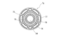
- the proximal end flange portion 73 includes an outer collar 77 and an inner collar 78 that slightly extend in the rear end direction from the flat plate portion.
- the outer collar 77 and the inner collar 78 are provided concentrically.
- the tips (free ends) of the outer collar 77 and the inner collar 78 are flat.
- the front end (free end) of the inner collar 78 protrudes slightly from the front end (free end) of the outer collar 77.
- the distal end portion 71 protruding from the main body portion 70 is a cylindrical portion extending a predetermined length with substantially the same outer diameter.
- the tip 71 is shorter than the main body 70.
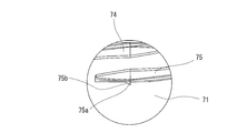
- the distal end portion 71 projects forward from the vicinity of the center of the distal end side flange portion 72 of the main body portion 70. Further, the distal end portion 71 is not in contact with the inner surface of the distal end portion of the gasket body 6 in a normal state where the gasket body 6 is not deformed. Then, spiral ribs 74 and 75 are formed on the outer surface of the distal end portion of the distal end portion 71 of the plunger mounting member 7. Further, in the plunger mounting member 7 in this embodiment, as shown in FIGS.
- spiral ribs 74 and 75 are formed.
- the spiral ribs 74 and 75 have a start end near the tip end of the tip end portion 71 of the plunger mounting member 7 and extend toward the rear end side by a predetermined length.
- the spiral rib may be only one strip (one).
- the height of the annular protrusion of the gasket body and the height of the helical rib of the plunger mounting member are preferably as follows.
- the height of the annular protrusion of the gasket body is preferably 1.0 to 3.0 mm, and particularly preferably 1.5 to 2.5 mm.
- the height of the helical rib of the plunger mounting member is preferably 2.5 to 3.2 mm, particularly preferably 2.8 to 3.1 mm, and more preferably 2.95 to 3.05 mm.
- the width of the contact portion between the annular protrusion and the spiral rib is preferably 0.5 to 2.5 mm, and more preferably 1.0 to 2.3 mm.
- the inner diameter of the annular projecting portion of the gasket body is preferably 16.0 to 20.0 mm, particularly preferably 17.0 to 19.0 mm, and the outer diameter of the helical rib portion of the plunger mounting member. Is preferably 19.0 to 22.0 mm, particularly preferably 20.0 to 21.0 mm.
- the inner surface of the hollow portion of the plunger mounting member 7 is provided with a plunger mounting portion for storing and mounting a mounting tip 40 of the plunger 4 described later.
- the plunger mounting portion is provided with a spiral recess 79 for screwing with the spiral protrusion 42 (42a, 42b) of the mounting tip 40, a vicinity of the spiral recess 79 and on the tip side, and the mounting tip.
- 40 engaging ribs 76 for engaging with 40 engaging portions 41.
- the plunger mounting member 7 includes a diameter-enlarged opening 84 at the base end, and a helical recess 79 is provided on the inner surface of the lumen that is reduced in diameter from the diameter-enlarged opening. Yes.
- the spiral recess 79 has a start end at a position slightly on the front end side from the base end opening of the plunger mounting member 7 and extends to the front end side by a predetermined length.
- the spiral recess 79 includes two (two) spiral recesses. Although it is preferable to provide such a plurality (specifically, two strips) of spiral recesses, only one (one) spiral recess may be provided.
- the plunger mounting portion includes an engaging rib 76 provided in the vicinity of the helical recess 79 and on the distal end side. The engaging rib 76 engages with an engaging portion 41 of a mounting tip 40 of the plunger 4 described later.
- the inner surface of the engaging rib 76 is an annular tapered inner surface that is reduced in diameter toward the distal end side. By setting it as such, the approach and passage of the engaging part 41 of the plunger 4 mentioned later become easy. Further, the front end surface of the engaging rib 76 is an upright surface, in other words, an annular flat surface that is substantially orthogonal to the central axis of the main body 70. For this reason, the separation
- the engaging rib is preferably an annular rib, but may be a broken line (non-continuous).
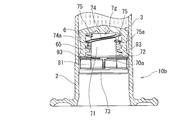
- a gasket 3 in which a plunger mounting member 7 is mounted on a gasket body 6 is housed in an outer cylinder 2.
- the base end of the plunger mounting member 7 does not substantially protrude from the base end of the outer cylinder 2.
- the plunger mounting member 7 is mounted on the gasket body 6 as follows. After inserting the helical ribs 74 and 75 of the plunger mounting member 7 into the starting end of the helical threaded portion 63 of the gasket body 6, the plunger mounting member 7 is rotated to rotate the helical ribs 74 and 75 together with the helical ribs 74 and 75.
- Screwing with the screwing portion 63 proceeds. Due to the progress of the screwing, the start ends of the helical ribs 74 and 75 of the plunger mounting member 7 approach the terminal end of the helical screwing portion 63 of the gasket body 6 and the missing portion 65 of the annular projecting portion 64, and the plunger mounting member 7 is located between the spiral protrusion 66 and the annular protrusion 64 forming the spiral threaded portion 63 of the gasket body 6.
- the spiral ribs 74 and 75 pass through the missing portion 65 of the annular projecting portion 64 and enter the storage portion 62 to continue the rotation of the plunger mounting member 7. As a result, as shown in FIG.
- the plunger mounting member 7 is idled. Furthermore, the rear end of the spiral rib does not enter the defective portion 65 of the annular projecting portion 64 regardless of which direction is rotated in the normal state, and the plunger mounting member is rotated by the rotation of the plunger mounting member 7. 7 and the rotation of the gasket body 6 are suppressed.
- the plunger mounting member 7 is mounted in a state where the gasket main body 6 stores the spiral ribs 74 and 75 in the storage portion 62, and the tip of the plunger mounting member 7 does not contact the inner surface of the gasket main body 6. .
- the plunger mounting member 7 A pressing portion 48 capable of pressing the proximal end surface of the proximal end flange portion 73 and a mounting distal end portion 40 protruding from the pressing portion 48 toward the distal end side and capable of entering the plunger mounting portion of the plunger mounting member 7 are provided.
- the distal end portion 42 of the plunger does not contact the inner surface of the gasket body 6.
- the plunger 4 includes a shaft portion 47 formed in a cross shape in cross section, and a pressing portion 48 is provided at the tip thereof.
- the pressing portion 48 is formed in a disc shape so that the base end surface of the plunger mounting member 7 can be pressed.
- a reinforcing rib 47a is provided in the middle of the shaft portion 47, and a plunger pressing portion 49 is provided at the proximal end.
- the mounting tip portion 40 of the plunger 4 is a small-diameter cylindrical portion that protrudes in the tip direction from the pressing portion 48, and a helical projection portion 42 (42a) that can be screwed into the helical recess 79 of the plunger mounting member 7.
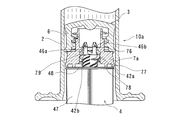
- the engaging portion 41 is formed at the tip of the plunger 4.
- the engaging portion 41 has a protrusion 46a formed on the outer surface of the claw portions 43a, 43b, 43c, 43d of the plunger 4, as shown in FIGS. , 46b, 46c, 46d.
- the protrusions 46a, 46b, 46c, and 46d are protrusions provided on the base end side of the predetermined length from the tips of the claw portions 43a, 43b, 43c, and 43d.
- the protrusions 46 a, 46 b, 46 c, 46 d get over the engagement rib 76 of the plunger mounting member 7 by the tip end 42 of the plunger 4 being pushed into the hollow portion of the plunger mounting member 7, and Engage.
- the plurality of claw portions 43a, 43b, 43c, and 43d are arranged on substantially the same circumference.
- the plurality of claw portions 43a, 43b, 43c, and 43d are provided in plural (specifically, four) so as to be equiangular with respect to the central axis of the plunger, and adjacent claw portions. Between them, slits 44a, 44b, 44c, and 44d are provided. The slits 44a, 44b, 44c, and 44d extend from the distal end of the distal end portion 42 to the proximal end side and beyond the formation portions of the projections 46a, 46b, 46c, and 46d.
- the outer surfaces of the claw portions 43a, 43b, 43c, and 43d are inclined surfaces 45a, 45b, 45c, and 45d that are inclined from the distal end side of the claw portion toward the projection portion. By setting it as such, engagement with the engagement rib 76 of the plunger mounting member 7 becomes easy.
- the claw portions 43a, 43b, 43c, and 43d are slightly elastically deformed inward when mounted on the plunger mounting member 7.
- the rear end surfaces of the protrusions 46 a, 46 b, 46 c, 46 d are standing surfaces, in other words, annular flat surfaces that are substantially orthogonal to the central axis of the plunger 4. For this reason, the separation
- a spiral protrusion 42 is provided near the engaging portion 41 and on the proximal end side.
- a spiral protrusion 42 (42a, 42b) is formed on the outer surface of the central portion of the cylindrical portion forming the mounting tip 40.
- two (two) helical protrusions 42 a is formed in the plunger 4 in this embodiment.
- the spiral protrusions 42a and 42b are short spirals having a start end and a terminal end at the center of the cylindrical portion forming the mounting tip 40 of the plunger 4. It is preferable to provide a plurality of (specifically, two) spiral protrusions as described above. However, like the mounting tip 40a of the plunger 4a shown in FIG. Book) only.
- wearing and the height of the helical protrusion part of a plunger are as follows.
- the depth of the annular recess of the plunger mounting member 7 is preferably 1.0 to 3.0 mm, and particularly preferably 1.5 to 2.5 mm.
- the height of the helical protrusion of the plunger is preferably 2.5 to 3.2 mm, particularly preferably 2.8 to 3.1 mm, and more preferably 2.95 to 3.05 mm.
- the width of the contact portion between the annular recess and the spiral protrusion is preferably 0.5 to 2.5 mm, and more preferably 1.0 to 2.3 mm. Further, the inner diameter (D1; FIG.
- the engaging rib 76 of the plunger mounting member is preferably 7 to 9 mm, particularly preferably 7.5 to 8.5 mm, and the outer surface of the plunger in the helical projection is outside.
- the diameter (D2: FIG. 14) is preferably 10 to 14 mm, and particularly preferably 10 to 13 mm.
- the outer diameter (D3: FIG. 14) of the engaging portion 41 portion that engages with the engaging rib 76 of the plunger mounting member 7 is preferably 7.5 to 10.5 mm, particularly 9 to 10 mm. Is preferred.
- flat portions 42c and 42d are provided at the tip end portions of the spiral protrusions 42a and 42b.
- the helical protrusion parts 42a and 42b are extended in the base end side spirally from the base end of this flat part.
- the mounting distal end portion 40 of the plunger 4 may be provided with a spiral rib 85 whose height is lower than that of the spiral protrusion 42 on the outer surface on the proximal end side of the spiral protrusion 42 (42a, 42b). . As shown in FIG.
- the helical rib 85 is formed so as to face the helical crest 79 a that forms the helical recess 79 of the plunger mounting member 7 when the plunger 4 is mounted on the plunger mounting member 7. Has been. For this reason, the clearance when the plunger 4 is mounted on the plunger mounting member 7 is reduced, and rattling is suppressed.
- a hard or semi-rigid resin such as high-density polyethylene, polypropylene, polystyrene, or polyethylene terephthalate.
- the outer cylinder 2 is a cylindrical body formed of a transparent or translucent material, preferably a material having low oxygen permeability and water vapor permeability. As shown in FIGS. 1, 2, and 17, the outer cylinder 2 includes a nozzle portion 22 and a collar 23.
- the nozzle portion 22 is provided at the distal end of the outer cylinder 2, and is provided with a distal end opening for discharging a chemical solution and the like in the outer cylinder, and is formed so as to decrease in diameter in a tapered shape toward the distal end.
- the collar 23 is formed in a cylindrical shape concentrically with the nozzle portion 22 so as to surround the nozzle portion 22.
- the collar 23 is open at the tip, and the inner diameter and outer diameter of the collar 23 are substantially the same from the base end to the tip. Further, the tip of the nozzle portion 22 protrudes from the tip opening of the collar 23, and the nozzle portion 22 and the tip of the collar 23 accommodate the nozzle portion 22 and the collar 23 in a sealing member (seal cap) 5. It is chamfered to make it easier.
- a screw groove (external cylinder side screwing) for screwing with a screw thread (cap side screwing part) 54 formed in a nozzle housing part 53 of a sealing member (seal cap) 5 described later. Part) 25 is formed.
- the outer cylinder 2 and the seal cap 5 are screwed between the collar inner peripheral surface and the nozzle housing portion outer peripheral surface.
- the thread groove (outer tube side screwing portion) 25 is a portion to which the injection needle (the hub of the injection needle) is attached after the seal cap 5 is removed from the outer tube.
- the outer cylinder has a flange 24.
- the flange 24 is an elliptical donut-shaped disk portion formed so as to protrude in the vertical direction from the entire rear end circumference of the outer cylinder 2.
- the flange 24 includes two gripping portions that are wide and face each other, and a plurality of ribs are formed on the front end surface side of the gripping portion.
- Examples of the material for forming the outer cylinder 2 include polypropylene, polyethylene, polystyrene, polyamide, polycarbonate, polyvinyl chloride, poly- (4-methylpentene-1), acrylic resin, acrylonitrile-butadiene-styrene copolymer, polyethylene terephthalate.
- Various resins such as polyester and cyclic polyolefin can be used, and among them, resins such as polypropylene and cyclic polyolefin are preferable because they are easy to mold and have heat resistance.
- the seal cap 5 that is a sealing member includes a closed end 51, a nozzle storage portion 53, and a color storage portion 52.
- the nozzle storage portion 53 is provided in the center portion of the seal cap 5 and has a cylindrical shape with a closed end.
- the inner diameter of the nozzle storage portion 53 is made slightly larger than that of the nozzle portion 22 and is slightly tapered from the distal end to the proximal end toward the proximal end, and accommodates the entire nozzle portion from the proximal end opening. ing.
- a seal member 55 for sealing the tip opening of the outer cylinder 2 in a liquid-tight manner is accommodated in the inner closed surface of the nozzle storage portion 53 (the inner surface of the closed end 51).
- the seal member 55 is preferably an elastic member so that the tip opening of the outer cylinder 2 can be sealed in a liquid-tight manner.
- a material for forming the seal member it is preferable to use, for example, natural rubber, isoprene rubber, butadiene rubber, fluororubber, silicone rubber, or other synthetic rubber, or thermoplastic elastomer such as olefin elastomer or styrene elastomer.
- a screw thread (cap side screwing portion) 54 for screwing with a screw groove (outer tube side screwing portion) 25 formed on the inner surface of the collar 23 of the outer tube 2. Is formed. Thereby, the outer cylinder 2 and the seal cap 5 are screwed between the outer surface of the nozzle housing portion and the inner surface of the collar.
- the color storage unit 52 is a cylindrical body that is formed so as to surround the nozzle storage unit 53 and has a closed end, and stores the collar 23 between the inner surface of the color storage unit and the outer surface of the nozzle storage unit. Further, the color storage portion 52 formed in a cylindrical shape is concentric with the nozzle storage portion 53, and the inner diameter of the color storage portion 52 is substantially the same from the front end to the base end. In addition, as shown in FIG. 1, the outer surface of the seal cap 5 (the outer peripheral surface of the color storage portion 52) is chopped in the vertical direction so that fingers do not slip when the seal cap is rotated. ing.
- Examples of the material for forming the seal cap include polypropylene, polyethylene, polystyrene, polyamide, polycarbonate, polyvinyl chloride, poly- (4-methylpentene-1), acrylic resin, acrylonitrile-butadiene-styrene copolymer, polyethylene terephthalate, etc.
- various resins such as polyester and cyclic polyolefin are preferable.
- resins such as polypropylene and cyclic polyolefin are preferable because they are easy to mold and have heat resistance.
- medical agent storage part formed in the outer cylinder is filled with the chemical
- the drug 8 any drug can be used.
- cyclosporine, benzodiazepine drugs, sodium chloride injection, vitamins, minerals, etc., powders such as antibiotics and protein preparations, or freeze-dried Drugs or liquids are used.
- the prefilled syringe of the present invention is particularly suitable for a prefilled syringe of the type that is administered using a syringe pump.
- the medicine to be filled is preferably a medicine suitable for using such administration means, and nitro Examples include glycerin injection, isosorbide nitrate injection, dopamine hydrochloride (dopamine hydrochloride) injection, dobutamine hydrochloride injection, morphine hydrochloride injection, and the like.
- or FIG. The prefilled syringe body 10 is in a state in which the gasket 3 is housed in the proximal end portion of the outer cylinder 2. As shown in FIG. 19, the plunger 4 is entered from the mounting tip 40 while rotating into the hollow portion of the plunger mounting member 7. As a result, the helical recess 79 of the plunger mounting portion of the plunger mounting member 7 and the spiral protrusion 42 (42a, 42b) of the mounting tip 40 of the plunger 4 are screwed together.
- the engaging portion 41 of the mounting tip 40 advances in the direction of the engaging rib 76 of the plunger mounting member 7, and the projections 46a, 46b, 46c, 46d of the claw portions 43a, 43b, 43c, 43d of the plunger 4
- the protrusions 46a, 46b, 46c, 46d and the engagement ribs 76 of the plunger attachment member 7 are engaged with each other as shown in FIGS.
- the mounting of the plunger 4 to the main body 10 is completed. In this way, in this prefilled syringe, the rotation operation of the plunger causes the engaging portion 41 of the mounting tip 40 of the plunger 4 and the engaging rib 76 of the plunger mounting member 7 to be engaged.
- the engagement between the engaging rib of the plunger mounting portion and the engaging portion of the plunger can be confirmed by bodily sensation.
- the mounted plunger is locked by the engaging rib 76 of the plunger mounting member 7 and is not detached.
- the plunger mounting member 7 may also rotate following the rotation.
- the helical rib forming portion of the distal end portion 71 of the plunger mounting member 7 is the gasket body 6. In the state of being accommodated in the accommodating portion 62, the plunger mounting member 7 is idled, so that the rotation of the plunger 4 is not transmitted to the gasket body 6.
- FIG. 22 and FIG. 23 includes a prefilled syringe body 10a and a plunger 4 that can be attached to the prefilled syringe body 10a (gasket 3) and is not attached.
- the prefilled syringe main body 10a is formed in the outer cylinder 2, the sealing member 5 that seals the tip opening of the outer cylinder 2, the gasket 3 that is slidably accommodated in the outer cylinder, and the outer cylinder 2.
- the gasket 3 includes a gasket body 6 and a plunger mounting member 7 a attached to the gasket body 6.
- the difference between the prefilled syringe 50 of this embodiment and the prefilled syringe 1 described above is only the plunger mounting member of the gasket 3, and the gasket body, outer cylinder, plunger and the like are the same. Only the members will be described.
- the gasket 6 is positioned on the distal end side by a predetermined length from the rear end opening of the outer cylinder 2, and the base end of the plunger mounting member 7a is from the rear end opening of the outer cylinder 2.
- the space between the proximal end opening of the outer cylinder 2 and the proximal end of the plunger mounting member 7a serves as a guiding portion for guiding the plunger 4 to the plunger mounting member 7a.
- the plunger mounting member 7a is a cylindrical body having a predetermined length having a hollow portion penetrating from one end to the other end.
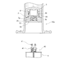
- the plunger mounting member 7a includes a main body portion 70a, a front end portion 71 that protrudes forward from the main body portion 70a and can be stored in the inner cavity portion of the gasket main body 6, and a proximal end of the main body portion 70a, as in the above-described embodiment.
- the main body portion 70a is a cylindrical portion having a predetermined length that is shorter in the axial direction than the main body portion 70 of the plunger mounting member 7 described above, and includes a plunger mounting portion at a base end portion thereof.
- the gasket main body 6 is located in the site
- the proximal end of the member 7a is also located at a position that is a distal end side of a predetermined length from the proximal end opening of the outer cylinder 2.
- the guide portion (distance between the base end opening of the outer cylinder 2 and the base end of the plunger mounting member 7a) is preferably 15 to 40 mm, and particularly preferably 20 to 30 mm.
- the cylindrical main body part 70a includes a side plate part 81 extending in the axial direction on the side surface.
- a disc-shaped distal flange portion 72 capable of pressing the proximal end surface of the gasket main body 6 is provided.
- the base end of the main body 70 a is provided with a disc-shaped base end side flange 73 that can come into contact with the pressing portion 48 of the plunger 4.
- the plurality of side plate portions 81 connect the distal end side flange portion 72 and the proximal end side flange portion 73 and reinforce both flange portions.
- the outer flange 72 has a substantially circular outer edge, and the outer diameter is slightly smaller than the outer diameter of the base end of the gasket body 6.
- the front end side peripheral edge part of the front end side flange part 72 is a substantially flat surface, and is in contact with the rear end surface of the gasket main body 6 so that it can be pressed.
- the proximal end flange portion 73 includes a flat plate portion and a collar portion extending from the flat plate portion toward the rear end by a predetermined length.
- the proximal end flange portion 73 includes an outer collar 77 and an inner collar 78 that slightly extend in the rear end direction from the flat plate portion.
- the outer collar 77 and the inner collar 78 are provided concentrically.
- the tips (free ends) of the outer collar 77 and the inner collar 78 are flat.
- the front end (free end) of the inner collar 78 protrudes slightly from the front end (free end) of the outer collar 77.
- the front end portion 71 protruding from the main body portion 70a is a cylindrical portion extending a predetermined length with substantially the same outer diameter.
- the tip 71 is longer than the main body 70a.
- the distal end portion 71 projects forward from the vicinity of the center of the distal end side flange portion 72 of the main body portion 70a. Further, the distal end portion 71 is not in contact with the inner surface of the distal end portion of the gasket body 6 in a normal state where the gasket body 6 is not deformed.
- the helical ribs 74 and 75 are formed in the outer surface of the front-end
- the spiral ribs 74 and 75 have a start end near the tip end of the tip end portion 71 of the plunger mounting member 7a, and extend to the rear end side of a predetermined length.
- the spiral rib may be only one strip (one).
- the height of the annular protrusion of the gasket body and the height of the helical rib of the plunger mounting member are preferably as follows.
- the height of the annular protrusion of the gasket body is preferably 1.0 to 3.0 mm, and particularly preferably 1.5 to 2.5 mm.
- the height of the helical rib of the plunger mounting member is preferably 2.5 to 3.2 mm, particularly preferably 2.8 to 3.1 mm, and more preferably 2.95 to 3.05 mm.
- the width of the contact portion between the annular protrusion and the spiral rib is preferably 0.5 to 2.5 mm, and more preferably 1.0 to 2.3 mm.
- the inner diameter of the annular projecting portion of the gasket body is preferably 16.0 to 20.0 mm, particularly preferably 17.0 to 19.0 mm, and the outer diameter of the helical rib portion of the plunger mounting member. Is preferably 19.0 to 22.0 mm, particularly preferably 20.0 to 21.0 mm.
- the gasket body 6 includes a helical protrusion 66 for forming the helical screw portion 63, and the plunger mounting member 7a is similar to the above-described embodiment.
- the tip 71 Provided on the outer surface of the tip 71 that can be accommodated in the inner cavity of the gasket body 6, and contacts the spiral protrusion 66 of the gasket body 6 when mounted on the gasket body 6, for mounting the plunger in the gasket body 6.
- the rib which becomes the rotational resistance of the member 7a is provided.
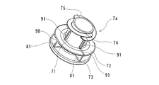
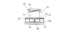
- the plunger mounting member 7a of this embodiment is provided with the axial rib 91 provided on the side surface of the cylindrical distal end portion 71 which is closer to the proximal end side than the above-described spiral ribs 74 and 75 forming portion.
- a plurality of axial ribs 91 are provided. In the case where a plurality of axial ribs 91 are provided, it is preferable that they are arranged at substantially equal angles with respect to the central axis of the tip 71. Then, as shown in FIGS.
- the axial rib 91 comes into contact with a spiral projection 66 formed on the inner surface of the gasket body 6 (contact with a predetermined frictional force or more), and the The idling of the plunger mounting member 7a is restricted.
- the axial rib 91 of the plunger mounting member 7 a slightly presses the spiral protrusion 66 of the gasket body 6.
- the axial rib 91 starts from the distal flange portion 72 and extends in the distal direction of the plunger mounting member 7a and parallel to the central axis of the plunger mounting member 7a.
- the height of the axial rib 91 of the plunger mounting member is preferably about 0.5 to 2 mm. Further, the number of axial ribs is preferably about 2 to 8, particularly 3 to 6. Further, the diameter of the circle passing through the outer surface of the axial rib 91 of the plunger mounting member is preferably slightly larger than the diameter of the circle passing through the outer surface of the spiral protrusion 66 of the gasket body 6, and is particularly larger by 1 to 2 mm. Preferably there is.
- a rib that extends from the peripheral edge of the distal end side flange portion 72 toward the center of the plunger mounting member 7a and reaches the above-described axial rib 91. 93 is provided. Two ribs 93 are provided so as to face each other. This rib prevents the gasket and the mounting member from spinning around by pressing the rib against the gasket when assembling while pushing the plunger.
- a concave portion 90 is provided on the side surface of the distal end side flange portion 72. Two recesses 90 are provided so as to face each other.
- the inner surface of the hollow portion of the plunger mounting member 7a is provided with a plunger mounting portion for storing and mounting the mounting tip 40 of the plunger 4 in the same manner as the plunger mounting member 7 described above.
- the plunger mounting portion is provided with a spiral recess 79 for screwing with the spiral protrusion 42 (42a, 42b) of the mounting tip 40, a vicinity of the spiral recess 79 and on the tip side, and the mounting tip.
- 40 engaging ribs 76 for engaging with 40 engaging portions 41.
- the plunger mounting member 7a includes a diameter-enlarged opening 84 at the base end, and a helical recess 79 is provided on the inner surface of the lumen that is reduced in diameter from the diameter-enlarged opening.
- the spiral recess 79 has a start end at a position slightly on the front end side from the base end opening of the plunger mounting member 7a, and extends to the front end side by a predetermined length.
- the spiral recess 79 includes two (two) spiral recesses. Although it is preferable to provide such a plurality (specifically, two strips) of spiral recesses, only one (one) spiral recess may be provided.
- the plunger mounting portion includes an engaging rib 76 provided in the vicinity of the helical recess 79 and on the distal end side. The engaging rib 76 is engaged with the engaging portion 41 of the mounting tip 40 of the plunger 4 described above.
- the inner surface of the engaging rib 76 is an annular tapered inner surface that is reduced in diameter toward the distal end side. By setting it as such, the approach and passage of the engaging part 41 of the plunger 4 mentioned later become easy. Further, the front end surface of the engaging rib 76 is an upright surface, in other words, an annular flat surface substantially orthogonal to the central axis of the main body 70a. For this reason, the separation
- the engaging rib is preferably an annular rib, but may be a broken line (non-continuous).
- a constituent material of the plunger mounting member 7a it is preferable to use a hard or semi-rigid resin such as high-density polyethylene, polypropylene, polystyrene, or polyethylene terephthalate.
- the gasket 3 in which the plunger mounting member 7 a is mounted on the gasket body 6 is housed in the outer cylinder 2. And the base end of the member 7a for plunger mounting
- the plunger mounting member 7a is mounted on the gasket body 6 as follows.
- the plunger mounting member 7a After inserting the helical ribs 74 and 75 of the plunger mounting member 7a into the starting end of the helical threaded portion 63 of the gasket body 6, the plunger mounting member 7a is rotated to rotate the helical ribs 74 and 75 and Screwing with the screwing portion 63 proceeds. Further, during the progress of the screwing, the axial rib 91 of the plunger mounting member 7a advances while slightly pressing the spiral protrusion 66 of the gasket body 6 and slidingly contacting it.
- the start ends of the spiral ribs 74 and 75 of the plunger mounting member 7a approach the end of the spiral threading portion 63 of the gasket body 6 and the missing portion 65 of the annular projecting portion 64, and the plunger mounting
- the starting ends of the spiral ribs 74 and 75 of the member 7 a are located between the spiral protrusion 66 and the annular protrusion 64 that form the spiral threaded portion 63 of the gasket body 6.
- FIG. 29 and FIG. 29 The prefilled syringe body 10a is in a state in which the gasket 3 is housed on the distal end side by a predetermined length from the proximal end of the outer cylinder 2.
- the plunger 4 is inserted into the outer cylinder from the base end opening of the outer cylinder 2, and is further entered while being rotated into the hollow portion of the plunger mounting member 7a.
- the helical recess 79 of the plunger mounting portion of the plunger mounting member 7a and the helical protrusion 42 (42a, 42b) of the mounting tip 40 of the plunger 4 are screwed together.
- the engaging portion 41 of the mounting tip 40 advances in the direction of the engaging rib 76 of the plunger mounting member 7a, and the projections 46a, 46b, 46c, 46d of the claw portions 43a, 43b, 43c, 43d of the plunger 4 are As shown in FIG. 30, the protrusions 46a, 46b, 46c, 46d and the engagement ribs 76 of the plunger attachment member 7a are engaged with each other, as shown in FIG. The mounting of the plunger 4 is completed.
- the plunger mounting member is placed in a state substantially parallel to the central axis of the outer cylinder.
- the plunger 4 can be mounted on the plunger mounting member 7a in a reliable and satisfactory state. Further, since the engaging portion 41 of the mounting tip portion 40 of the plunger 4 and the engaging rib 76 of the plunger mounting member 7a are engaged by rotating the plunger, the plunger mounting portion is engaged during operation. The engagement between the rib and the engaging portion of the plunger can be confirmed by bodily sensation. In addition, the mounted plunger is locked by the engaging rib 76 of the plunger mounting member 7a and is not detached. If the clearance between the inner cylinder inner diameter and the shaft portion 47 and the pressing portion 48 is small, the alignment of the engagement becomes more reliable.
- the plunger mounting member may be as shown in FIGS. 31 and 32.
- the only difference between the plunger mounting member 7 b of this embodiment and the above-described plunger mounting member 7 a is the presence or absence of the axial rib 91 provided on the side surface of the cylindrical tip portion 71.
- the plunger mounting member 7b does not include the axial rib 91 that the plunger mounting member 7a includes.
- the plunger mounting member may be as shown in FIGS. 33 and 34.
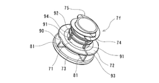
- the plunger mounting member 7 c of this embodiment does not have an axial rib like the plunger mounting member 7 a described above, and includes an annular rib 92 on the side surface of the cylindrical tip portion 71.
- the plunger mounting member 7c of this example includes an annular rib 92 provided on a side surface that is closer to the proximal end side than the spiral ribs 74 and 75 forming portion of the cylindrical distal end portion 71.
- the annular rib 92 has an endless shape provided so as to be orthogonal to the central axis of the plunger mounting member 7c.
- the annular rib 92 comes into contact with the spiral protrusion 66 formed on the inner surface of the gasket body 6 (contacts with a predetermined frictional force or more), and restricts idling of the plunger mounting member 7 c with respect to the gasket body 6. Specifically, when the plunger mounting member 7 c is mounted on the gasket body 6, the annular rib 92 of the plunger mounting member 7 c slightly presses the spiral protrusion 66 of the gasket body 6.
- the height of the annular rib 92 of the plunger mounting member is preferably about 0.5 to 2 mm. Further, the outer diameter of the annular rib 92 of the plunger mounting member is preferably slightly larger than the diameter of the circle through which the outer surface of the spiral projection 66 of the gasket body 6 passes, and particularly preferably larger by 1 to 2 mm.
- the plunger mounting member may be as shown in FIGS. 35 and 36.
- the plunger mounting member 7d of this embodiment does not have the axial rib like the plunger mounting member 7a described above, and the first annular rib 92 and the second annular rib 94 are formed on the side surface of the cylindrical tip portion 71. It has.
- the plunger mounting member 7d of this example includes a first annular rib 92 provided on the side surface that is closer to the base end side than the spiral ribs 74 and 75 forming portion of the cylindrical distal end portion 71. Yes.
- the first annular rib 92 has an endless shape provided so as to be orthogonal to the central axis of the plunger mounting member 7d.
- the first annular rib 92 is in contact with the spiral protrusion 66 formed on the inner surface of the gasket body 6 (contacted with a predetermined frictional force or more), and the plunger mounting member 7d is idled with respect to the gasket body 6. regulate. Specifically, when the plunger mounting member 7d is mounted on the gasket body 6, the first annular rib 92 of the plunger mounting member 7d slightly presses the spiral protrusion 66 of the gasket body 6. . Further, the plunger mounting member 7 d of this example includes a second annular rib 94 provided on a side surface between the above-described first annular rib 91 and the distal end side flange portion 72 of the cylindrical distal end portion 71. Yes.
- the second annular rib 94 has an endless shape provided so as to be orthogonal to the central axis of the plunger mounting member 7d.
- the second annular rib 94 also comes into contact with the spiral protrusion 66 formed on the inner surface of the gasket body 6 (contacts with a predetermined frictional force or more), and the idling of the plunger mounting member 7d with respect to the gasket body 6 is restricted.
- the second annular rib 94 of the plunger mounting member 7d slightly presses the spiral protrusion 66 of the gasket body 6. .
- the height of the first annular rib 92 and the second annular rib 94 of the plunger mounting member is preferably about 0.5 to 2 mm.
- the outer diameters of the first annular rib 92 and the second annular rib 94 of the plunger mounting member are preferably slightly larger than the diameter of the circle through which the outer surface of the spiral projection 66 of the gasket body 6 passes. It is preferable that it is larger by 2 mm.
- the number of the annular ribs is not limited to 1 or 2 as in the above-described embodiment, but may be 3 or more, preferably 1 to 3.
- the plunger mounting member may be as shown in FIGS. 37 and 38.
- the only difference between the plunger mounting member 7e of this embodiment and the above-described plunger mounting member 7a is that the plunger mounting member 7e includes an annular rib 92 provided on the side surface of the cylindrical tip 71.
- the plunger mounting member 7e of this example has axial ribs 91 provided on the side surfaces closer to the base end side than the spiral ribs 74 and 75 forming portions of the cylindrical distal end portion 71, like the plunger mounting member 7a. I have.
- a plurality of axial ribs 91 are provided.
- axial ribs 91 are arranged at substantially equal angles with respect to the central axis of the tip 71. 37 and 38, the axial rib 91 is in contact with the spiral projection 66 formed on the inner surface of the gasket body 6 (contact with a predetermined frictional force or more), and the The idling of the plunger mounting member 7e is restricted. Specifically, when the plunger mounting member 7 e is mounted on the gasket body 6, the axial ribs 91 of the plunger mounting member 7 e slightly press the helical protrusion 66 of the gasket body 6.
- the axial rib 91 starts from the distal flange portion 72, extends in the distal direction of the plunger mounting member 7e and parallel to the central axis of the plunger mounting member 7e, It terminates at a position slightly closer to the base end side than the formation portion of the spiral ribs 74 and 75.
- the plunger mounting member 7e of this example includes an annular rib 92 provided on the side surface which is closer to the base end side than the spiral ribs 74 and 75 forming portion of the cylindrical distal end portion 71.
- the annular rib 92 has an endless shape provided so as to be orthogonal to the central axis of the plunger mounting member 7e.
- the annular rib connects the ends of the plurality of axial ribs 91 described above.
- the annular rib 92 is also brought into contact with the spiral projection 66 formed on the inner surface of the gasket body 6 (contacted with a predetermined frictional force or more), and the idling of the plunger mounting member 7e with respect to the gasket body 6 is restricted.
- the annular rib 92 of the plunger mounting member 7 e slightly presses the spiral protrusion 66 of the gasket body 6.
- the height of the annular rib 92 of the plunger mounting member is preferably about 0.5 to 2 mm.
- the outer diameter of the annular rib 92 of the plunger mounting member is preferably slightly larger than the diameter of the circle through which the outer surface of the spiral projection 66 of the gasket body 6 passes, and particularly preferably larger by 1 to 2 mm.
- the plunger mounting member may be as shown in FIGS. 39 and 40.
- the difference between the plunger mounting member 7f of this embodiment and the above-described plunger mounting member 7a is that the plunger mounting member 7f includes the first annular rib 92 and the second annular rib 92 provided on the side surface of the cylindrical tip portion 71. It is only a point provided with the annular rib 94.
- the plunger mounting member 7f of this example has axial ribs 91 provided on the side surfaces closer to the base end side than the spiral ribs 74 and 75 forming portions of the cylindrical distal end portion 71, like the plunger mounting member 7a. I have. In particular, in this embodiment, a plurality of axial ribs 91 are provided.
- axial ribs 91 In the case where a plurality of axial ribs 91 are provided, it is preferable that they are arranged at substantially equal angles with respect to the central axis of the tip 71. As shown in FIGS. 39 and 40, the axial rib 91 comes into contact with the spiral protrusion 66 formed on the inner surface of the gasket body 6 (contact with a predetermined frictional force or more), and the The idling of the plunger mounting member 7f is restricted. Specifically, when the plunger mounting member 7 f is mounted on the gasket body 6, the axial rib 91 of the plunger mounting member 7 f slightly presses the spiral protrusion 66 of the gasket body 6.
- the axial rib 91 starts from the distal flange portion 72 and extends in the distal direction of the plunger mounting member 7f and parallel to the central axis of the plunger mounting member 7f. It terminates at a position slightly closer to the base end side than the formation portion of the spiral ribs 74 and 75.
- the plunger mounting member 7f of this example includes a first annular rib 92 provided on the side surface that is closer to the base end side than the spiral ribs 74 and 75 forming portion of the cylindrical distal end portion 71.
- the first annular rib 92 has an endless shape provided so as to be orthogonal to the central axis of the plunger mounting member 7f.
- the first annular rib connects the ends of the plurality of axial ribs 91 described above.
- the first annular rib 92 also comes into contact with the spiral projection 66 formed on the inner surface of the gasket body 6 (contact with a predetermined frictional force or more), and the idling of the plunger mounting member 7f with respect to the gasket body 6 is restricted. To do. Specifically, when the plunger mounting member 7f is mounted on the gasket body 6, the first annular rib 92 of the plunger mounting member 7f slightly presses the spiral protrusion 66 of the gasket body 6. .
- the plunger mounting member 7 f of this example includes a second annular rib 94 provided on a side surface between the above-described first annular rib 91 and the distal end side flange portion 72 of the cylindrical distal end portion 71. Yes.
- the second annular rib 94 has an endless shape provided so as to be orthogonal to the central axis of the plunger mounting member 7f. Furthermore, in this example, the second annular rib connects the intermediate portions of the plurality of axial ribs 91 described above.
- the second annular rib 94 also comes into contact with the spiral projection 66 formed on the inner surface of the gasket body 6 (contact with a predetermined frictional force or more), and the idling of the plunger mounting member 7f with respect to the gasket body 6 is restricted. To do. Specifically, when the plunger mounting member 7f is mounted on the gasket body 6, the second annular rib 94 of the plunger mounting member 7f also slightly presses the spiral protrusion 66 of the gasket body 6.
- the height of the first annular rib 92 and the second annular rib 94 of the plunger mounting member is preferably about 0.5 to 2 mm.
- the outer diameters of the first annular rib 92 and the second annular rib 94 of the plunger mounting member are preferably slightly larger than the diameter of the circle through which the outer surface of the spiral projection 66 of the gasket body 6 passes. It is preferable that it is larger by 2 mm.
- the plunger mounting member may be as shown in FIGS. 41 to 49.
- the plunger mounting member 7g is a cylindrical body having a predetermined length having a hollow portion penetrating from one end to the other end.
- the plunger mounting member 7g is protruded forward from the main body portion 70a and the main body portion 70a in the same manner as the plunger mounting members 7, 7a, 7b of the above-described embodiments, and can be stored in the lumen portion of the gasket main body 6.
- the main body portion 70a is a cylindrical portion having a predetermined length that is shorter in the axial direction than the main body portion 70 of the plunger mounting member 7 described above, and includes a plunger mounting portion at a base end portion thereof.
- the gasket main body 6 is located in the site
- the base end of the member 7g is also located at a portion that is a tip end side of a predetermined length from the base end opening of the outer cylinder 2.
- the guide portion (distance between the base end opening of the outer cylinder 2 and the base end of the plunger mounting member 7g) is preferably 15 to 40 mm, and particularly preferably 20 to 30 mm.
- the cylindrical main body part 70a includes a side plate part 81 extending in the axial direction on the side surface.
- a disc-shaped distal flange portion 72 capable of pressing the proximal end surface of the gasket main body 6 is provided.
- the base end of the main body 70 a is provided with a disc-shaped base end side flange 73 that can come into contact with the pressing portion 48 of the plunger 4.
- the plurality of side plate portions 81 connect the distal end side flange portion 72 and the proximal end side flange portion 73 and reinforce both flange portions.
- the outer flange 72 has a substantially circular outer edge, and the outer diameter is slightly smaller than the outer diameter of the base end of the gasket body 6.
- the front end side peripheral edge part of the front end side flange part 72 is a substantially flat surface, and is in contact with the rear end surface of the gasket main body 6 so that it can be pressed.
- the proximal end flange portion 73 includes a flat plate portion and a collar portion extending from the flat plate portion in the rear end direction by a predetermined length.
- the base end side flange portion 73 includes an outer collar 77 and an inner collar 78 that slightly extend in the rear end direction from the flat plate portion.
- the outer collar 77 and the inner collar 78 are provided concentrically.
- the tips (free ends) of the outer collar 77 and the inner collar 78 are flat.
- the front end (free end) of the inner collar 78 protrudes slightly from the front end (free end) of the outer collar 77.
- the front end portion 71 protruding from the main body portion 70a is a cylindrical portion extending a predetermined length with substantially the same outer diameter.
- the tip 71 is longer than the main body 70a.
- the distal end portion 71 projects forward from the vicinity of the center of the distal end side flange portion 72 of the main body portion 70a. Further, the distal end portion 71 is not in contact with the inner surface of the distal end portion of the gasket body 6 in a normal state where the gasket body 6 is not deformed.
- the helical ribs 74 and 75 are formed in the outer surface of the front-end
- spiral rib 74, 75 In the plunger mounting member 7g in this embodiment, as shown in FIGS. 41 to 45 and FIGS. 47 to 49, two strips (two This is a spiral rib 74, 75.
- the spiral ribs 74 and 75 have a start end near the tip end of the tip end portion 71 of the plunger mounting member 7g and extend to the rear end side of a predetermined length.
- the spiral rib may be only one strip (one).
- the height of the annular protrusion 64 of the gasket body and the height of the helical rib of the plunger mounting member are preferably as follows.
- the height of the annular protrusion of the gasket body is preferably 1.0 to 3.0 mm, and particularly preferably 1.5 to 2.5 mm.
- the height of the helical rib of the plunger mounting member is preferably 2.5 to 3.2 mm, particularly preferably 2.8 to 3.1 mm, and more preferably 2.95 to 3.05 mm.
- the inner diameter of the annular projecting portion of the gasket body is preferably 16.0 to 20.0 mm, particularly preferably 17.0 to 19.0 mm, and the outer diameter of the helical rib portion of the plunger mounting member.
- a rib 93 is provided on the distal end surface of the distal end flange portion 72. Specifically, a rib 93 extending from the periphery in the center direction of the plunger mounting member 7g and reaching the above-described tip end 71 is provided. Two ribs 93 are provided so as to face each other. This rib prevents the gasket and the mounting member from spinning around by pressing the rib against the gasket when assembling while pushing the plunger.
- the inner surface of the hollow part of the plunger mounting member 7g is provided with a plunger mounting part for storing and mounting the mounting tip 40 of the plunger 4 in the same manner as the plunger mounting member 7 described above.
- the plunger mounting portion is provided with a spiral recess 79 for screwing with the spiral protrusion 42 (42a, 42b) of the mounting tip 40, and near and on the tip side of the spiral recess 79, and the mounting tip And 40 engaging ribs 76 for engaging with 40 engaging portions 41. As shown in FIGS.
- the plunger mounting member 7g includes a diameter-enlarged opening 84 at the base end, and a helical recess 79 is formed on the inner surface of the lumen that is reduced in diameter from the diameter-enlarged opening. Is provided.
- the spiral recess 79 has a start end at a position slightly on the tip side from the base end opening of the plunger mounting member 7g, and extends to the tip end side by a predetermined length.
- the spiral recess 79 includes two (two) spiral recesses. Although it is preferable to provide such a plurality (specifically, two strips) of spiral recesses, only one (one) spiral recess may be provided.
- the plunger mounting portion includes an engaging rib 76 provided in the vicinity of the helical recess 79 and on the distal end side.
- the engaging rib 76 is engaged with the engaging portion 41 of the mounting tip 40 of the plunger 4 described above.
- the inner surface of the engaging rib 76 is an annular tapered inner surface that is reduced in diameter toward the distal end side. By setting it as such, the approach and passage of the engaging part 41 of the plunger 4 mentioned later become easy.
- the front end surface of the engaging rib 76 is an upright surface, in other words, an annular flat surface substantially orthogonal to the central axis of the main body 70a. For this reason, the separation
- the engaging rib is preferably an annular rib, but may be a broken line (non-continuous).
- a hard or semi-hard resin such as high density polyethylene, polypropylene, polystyrene, polyethylene terephthalate.
- the spiral ribs 74 and 75 provided on the outer surface of the distal end portion 71 of the plunger mounting member are shown in FIGS. 42, 43, 44, and 43. 48 and FIG. 49, which is an enlarged view of the round broken line part of FIG. 44, which is an enlarged view of the round broken line part, are preferably provided.
- the spiral ribs 74 and 75 are protruding portions provided on the base end surface of the base end portion. 74a, 75a.
- the projecting portions 74 a and 75 a are provided so as to project from the base end surface of the base end portion of the spiral ribs 74 and 75 toward the disc-shaped front end flange portion 72 that can press the base end surface of the gasket body 6. .
- the plunger The resistance force between the gasket and the plunger mounting member is smaller than between the mounting member and the plunger, and this prevents the plunger and the plunger mounting member from rotating together against the gasket and making it difficult to mount.
- Protrusions 74a and 75a provided on the base end surfaces of the base end portions of the spiral ribs 74 and 75 function to prevent idling of the plunger mounting member with respect to the gasket.
- the protrusion parts 74a and 75a are provided in the base end part of the spiral ribs 74 and 75, especially the position which becomes a predetermined length front end side from a base end.
- the spiral ribs 74 and 75 have, at the base end portion, end portions that are not spiral but are substantially orthogonal to the central axis of the plunger mounting member 7g (the central axis of the distal end portion 71).
- the end width of the end portion of the end portion gradually decreases toward the base end (terminal end) in the protruding width (the protruding width with respect to the side surface of the distal end portion 71 of the plunger mounting member 7g).
- the protrusions 74a and 75a are spiral with respect to the central axis of the plunger mounting member 7g of the spiral ribs 74 and 75 (the central axis of the tip 71). It is provided at the end portion that is substantially orthogonal. Furthermore, in this embodiment, the projecting portions 74a and 75a are provided in portions where the projecting widths of the spiral ribs 74 and 75 maintain the normal width (portions that are not reduced in width).
- the protrusion height of the protrusions 74a and 75a with respect to the base end surface of the base end of the spiral ribs 74 and 75 is preferably 0.1 to 1 mm, and particularly preferably 0.2 to 0.5 mm. Moreover, it is preferable that the protrusion parts 74a and 75a have a pointed apex part (edge part).
- the protrusions 74a and 75a preferably have a substantially triangular cross section. As shown in FIGS. 48 and 49, the angle at the apex of the protrusions 74a and 75a is preferably 15 to 60 degrees. If the angle is less than 15 degrees, the strength may be reduced and there is a risk of breakage.
- the rib 93 is provided on the distal end surface of the distal end side flange portion 72, and the protruding portion 74a of the spiral rib 74 is formed on the distal end side flange. Facing one rib 93 provided in the portion 72 (specifically, facing the axial direction, in other words, on the same straight line parallel to the central axis of the plunger mounting member 7g) ). Similarly, the projecting portion 75a of the spiral rib 75 is also opposed to the other rib 93 provided on the distal end side flange portion 72 (specifically, facing the axial direction, in other words, the plunger mounting member).
- the gasket is formed by the protruding portion 74a of the spiral rib 74 and one rib 93 of the distal end side flange portion 72. Similarly, the gasket is sandwiched between the projecting portion 75a of the spiral rib 75 and the other rib 93 of the front end side flange portion 72, so that slipping between the two can be more reliably prevented.
- the prefilled syringe 10 b of this embodiment as shown in FIG.
- the gaskets are formed at the tip end (edge portion) of the protrusion 74 a of the spiral rib 74 and the tip end of one rib 93 ( The edge portion is in a state of biting into the gasket body 6 and can more reliably prevent idling of the gasket body 6 and the plunger mounting member 7g.
- the plunger mounting member 7g of this embodiment is attached to the gasket body 6 as in the prefilled syringe 50 of the embodiment shown in FIGS.
- the gasket 3 to which 7 g is attached is accommodated in the outer cylinder 2.
- the proximal end of the plunger mounting member 7g does not substantially protrude from the proximal end of the outer cylinder 2, and is positioned on the distal end side for a predetermined length.
- the plunger mounting member 7g is mounted on the gasket body 6 as follows.
- the plunger mounting member 7g is rotated to rotate the helical ribs 74 and 75 and the spiral shape. Screwing with the screwing portion 63 proceeds. Further, during the progress of screwing, the axial rib 91 of the plunger mounting member 7g advances while slightly pressing the helical protrusion 66 of the gasket body 6 and slidingly contacting it.
- the start ends of the spiral ribs 74 and 75 of the plunger mounting member 7g approach the terminal end of the spiral screwing part 63 of the gasket body 6 and the missing part 65 of the annular projecting part 64, and the plunger mounting
- the starting ends of the spiral ribs 74 and 75 of the member 7g are positioned between the spiral protrusion 66 and the annular protrusion 64 that form the spiral threaded portion 63 of the gasket body 6.
- the entire spiral ribs 74 and 75 pass through the missing portion 65 of the annular protrusion 64, and the spiral rib forming portion of the distal end portion 71 of the plunger mounting member 7 g is
- the gasket body 6 is housed in the housing portion 62, and the distal end portion (edge portion) of the protruding portion 74 a of the spiral rib 74 and the distal end portion (edge portion) of one rib 93 of the distal end side flange portion 72 are the gasket body 6. And is sandwiched between the two ribs 93 of the projecting portions 74 a and 75 a of the spiral rib 75 and the front end side flange portion 72. Thereby, the mounting operation of the plunger mounting member 7g to the gasket body 6 is completed.
- the prefilled syringe of the present invention is as follows. (1) An outer cylinder, a gasket that is slidably accommodated in the outer cylinder, a sealing member that seals a distal end opening of the outer cylinder, and a medicine container that is formed in the outer cylinder A prefilled syringe body comprising a prefilled syringe body made of a stored medicine and a plunger that is attachable to the gasket and is in a non-attached state, wherein the gasket has a cylindrical shape whose front end is closed and whose rear end is open
- a gasket main body comprising a lumen portion extending from the rear end opening toward the front end side, and a plunger mounting member attached to the gasket main body, the plunger mounting member from one end to the other end Is a cylindrical body having a hollow portion penetrating up to, a main body portion having a distal end flange portion capable of pressing the proximal end surface of the gasket main body on the distal
- the plunger mounting A mounting tip that can enter the plunger mounting portion of the member, and the plunger mounting portion of the plunger mounting member is provided with a helical recess and a hook provided near and on the tip side of the spiral recess.
- a mounting rib of the plunger, the mounting tip of the plunger is provided in the vicinity of the spiral projecting portion and on the tip side of the spiral projecting portion that can be screwed with the spiral recess of the plunger mounting portion,
- An engagement portion that engages with the engagement rib of the plunger attachment portion, and the plunger attachment member is attached to the gasket body in a state where the helical rib is accommodated in the accommodation portion, and
- the front end of the plunger mounting member is not in contact with the inner surface of the gasket main body, and the plunger is positioned in front of the plunger when mounted on the gasket.
- Prefilled syringe mounting tip portion is assumed not in contact with the inner surface of the gasket body.
- the plunger can be attached to the gasket by rotating the plunger as in the case of a normal prefilled syringe.
- the prefilled syringe of the present invention does not cause liquid leakage due to compression during the operation of the outer cylinder.
- the plunger can be attached to the prefilled syringe body by inserting the tip end portion for attachment into the base end portion of the plunger attachment member, and the plunger attachment during the operation.
- the engaging rib of the part and the engaging part of the plunger are engaged, the engagement between the two can be confirmed. And even if the mounted plunger is rotated, the rotational force is transmitted to the plunger mounting member but is not transmitted to the gasket body, and the gasket is not deformed. Further, since the gasket body and the plunger mounting member are substantially loosely fitted, the gasket is not deformed even when the plunger is tilted, and liquid leakage is unlikely to occur.
- the plunger inserts the mounting distal end portion into the proximal end portion of the plunger mounting member, and rotates the plunger to thereby rotate the helical protrusion of the mounting distal end portion and the plunger mounting portion.
- the engagement of the member with the helical recess advances, and the engagement portion of the plunger advances to get over the engagement rib of the plunger mounting member to engage with the engagement rib.
- the engaging portion of the plunger When the engaging portion of the plunger is engaged with the engaging rib of the plunger mounting member, the helical protrusion of the plunger and the helical recess of the plunger mounting member are: The prefilled syringe according to the above (1) or (2), which is in a screwed state.
- the engaging portion of the plunger includes a plurality of claw portions provided at the tip end portion of the plunger and a protrusion portion provided on an outer surface of the claw portion.
- the engaging ribs of the plunger mounting member are annular ribs, and the inner surface of the annular rib is a tapered surface that decreases in diameter toward the distal end side.
- the gasket body includes an annular protrusion for preventing a plunger from being located near and on the tip side of the helical threaded portion, and the annular protrusion is the spiral of the body portion of the plunger mounting member.
- (1) further including a guide portion for guiding the spiral rib that has reached the annular projecting portion to the storage portion by the progress of screwing between the spiral rib and the spiral threaded portion of the gasket body. Thru
- the spiral protrusion of the plunger is a double spiral protrusion
- the spiral recess of the plunger is a double spiral recess corresponding to the double spiral protrusion.
- the prefilled syringe according to any one of 1) to (9).
- the prefilled syringe of the present invention is housed in an outer cylinder, a gasket housed in the outer cylinder, a sealing member for sealing the distal end opening of the outer cylinder, and a medicine container formed in the outer cylinder. It consists of a prefilled syringe body made of a medicine and a plunger that can be attached to the gasket and is not attached.
- the plunger mounting member is provided on a proximal end surface of the proximal end portion of the spiral rib and includes a projecting portion projecting in the distal end flange portion direction (1) to (10).
Landscapes
- Health & Medical Sciences (AREA)
- Vascular Medicine (AREA)
- Engineering & Computer Science (AREA)
- Anesthesiology (AREA)
- Biomedical Technology (AREA)
- Heart & Thoracic Surgery (AREA)
- Hematology (AREA)
- Life Sciences & Earth Sciences (AREA)
- Animal Behavior & Ethology (AREA)
- General Health & Medical Sciences (AREA)
- Public Health (AREA)
- Veterinary Medicine (AREA)
- Infusion, Injection, And Reservoir Apparatuses (AREA)
Abstract
Seringue pré-remplie (1) munie d'un joint (3) comportant un corps (6) de joint et un élément (7) de montage de poussoir. L'élément (7) de montage de poussoir se déplace librement par rapport au corps (6) de joint lorsque des parties de l'élément (7) de montage de poussoir, sur lesquelles sont formées des nervures hélicoïdales (74, 75), se trouvent dans un état où lesdites parties sont contenues à l'intérieur d'une section (62) de confinement du corps (6) de joint. Lorsque le poussoir (4) est introduit à l'intérieur d'une section creuse de l'élément (7) de montage de poussoir tout en subissant une rotation, la section (48) d'appui du poussoir appuie sur la surface d'extrémité de base de la section de bride de l'élément (7) de montage de poussoir côté extrémité de base, et une section (72) de bride de l'élément (7) de montage de poussoir côté extrémité avant appuie sur la surface d'extrémité de base du corps de joint. Une section (41) d'enclenchement du poussoir (4) coopère alors avec une nervure (76) d'enclenchement de l'élément (7) de montage de poussoir, le montage du poussoir (4) sur un corps (10) de seringue pré-remplie étant ainsi complété. L'extrémité avant de l'élément (7) de montage de poussoir et une section (40) de montage d'extrémité avant du poussoir (4), dans un état où le poussoir (4) est monté sur le joint (3), sont prévues pour ne pas entrer en contact avec la surface intérieure du corps (6) de joint.
Priority Applications (4)
| Application Number | Priority Date | Filing Date | Title |
|---|---|---|---|
| EP10820637.6A EP2484393B1 (fr) | 2009-09-30 | 2010-09-30 | Seringue pré-remplie |
| CN201080054294.6A CN102639174B (zh) | 2009-09-30 | 2010-09-30 | 预充式注射器 |
| JP2011534302A JP5567026B2 (ja) | 2009-09-30 | 2010-09-30 | プレフィルドシリンジ |
| US13/434,919 US9101720B2 (en) | 2009-09-30 | 2012-03-30 | Prefilled syringe |
Applications Claiming Priority (4)
| Application Number | Priority Date | Filing Date | Title |
|---|---|---|---|
| JP2009-228758 | 2009-09-30 | ||
| JP2009228758 | 2009-09-30 | ||
| JP2010-025996 | 2010-02-08 | ||
| JP2010025996 | 2010-02-08 |
Related Child Applications (1)
| Application Number | Title | Priority Date | Filing Date |
|---|---|---|---|
| US13/434,919 Continuation US9101720B2 (en) | 2009-09-30 | 2012-03-30 | Prefilled syringe |
Publications (1)
| Publication Number | Publication Date |
|---|---|
| WO2011040522A1 true WO2011040522A1 (fr) | 2011-04-07 |
Family
ID=43826334
Family Applications (1)
| Application Number | Title | Priority Date | Filing Date |
|---|---|---|---|
| PCT/JP2010/067076 WO2011040522A1 (fr) | 2009-09-30 | 2010-09-30 | Seringue pré-remplie |
Country Status (5)
| Country | Link |
|---|---|
| US (1) | US9101720B2 (fr) |
| EP (1) | EP2484393B1 (fr) |
| JP (1) | JP5567026B2 (fr) |
| CN (1) | CN102639174B (fr) |
| WO (1) | WO2011040522A1 (fr) |
Cited By (7)
| Publication number | Priority date | Publication date | Assignee | Title |
|---|---|---|---|---|
| WO2015033953A1 (fr) * | 2013-09-06 | 2015-03-12 | テルモ株式会社 | Tube externe pour seringue et seringue pré-remplie |
| WO2015151943A1 (fr) * | 2014-03-31 | 2015-10-08 | テルモ株式会社 | Seringue pré-remplie, remplie d'une solution d'injection de bromure de rocuronium |
| JPWO2014196056A1 (ja) * | 2013-06-06 | 2017-02-23 | テルモ株式会社 | 注射器およびプレフィルドシリンジ |
| JP2018158179A (ja) * | 2018-07-12 | 2018-10-11 | テルモ株式会社 | 注射器およびプレフィルドシリンジ |
| JP2019528833A (ja) * | 2016-09-27 | 2019-10-17 | オーウェン マンフォード リミテッドOwen Mumford Limited | ガスケットかみ合い部を備えた注射器およびプランジャーロッド |
| JP2020108858A (ja) * | 2018-07-12 | 2020-07-16 | テルモ株式会社 | 注射器およびプレフィルドシリンジ |
| WO2024034633A1 (fr) * | 2022-08-09 | 2024-02-15 | 株式会社根本杏林堂 | Cylindre externe de seringue, seringue et élément de support de seringue |
Families Citing this family (29)
| Publication number | Priority date | Publication date | Assignee | Title |
|---|---|---|---|---|
| AUPQ867900A0 (en) | 2000-07-10 | 2000-08-03 | Medrad, Inc. | Medical injector system |
| US7666169B2 (en) | 2003-11-25 | 2010-02-23 | Medrad, Inc. | Syringe and syringe plungers for use with medical injectors |
| US8926569B2 (en) | 2006-03-15 | 2015-01-06 | Bayer Medical Care Inc. | Plunger covers and plungers for use in syringes and methods of fabricating plunger covers and plungers for use in syringes |
| USD942005S1 (en) | 2007-03-14 | 2022-01-25 | Bayer Healthcare Llc | Orange syringe plunger cover |
| USD847985S1 (en) | 2007-03-14 | 2019-05-07 | Bayer Healthcare Llc | Syringe plunger cover |
| JP5431051B2 (ja) * | 2009-07-17 | 2014-03-05 | 株式会社大協精工 | 微少容量の注射器用ピストン及び該ピストンを取り付けたプランジャー |
| DK2550985T3 (da) * | 2011-07-25 | 2020-09-28 | Daikyo Seiko Ltd | Plungerstempelkit til medicinsprøjte |
| US9174003B2 (en) | 2012-09-28 | 2015-11-03 | Bayer Medical Care Inc. | Quick release plunger |
| CN103203052A (zh) * | 2013-04-03 | 2013-07-17 | 山东威高集团医用高分子制品股份有限公司 | 一种安全型预充式冲管注射器 |
| CN103170034A (zh) * | 2013-04-03 | 2013-06-26 | 山东威高集团医用高分子制品股份有限公司 | 一种预充式冲管注射器 |
| JP6199604B2 (ja) * | 2013-05-15 | 2017-09-20 | 住友ゴム工業株式会社 | 医療用ガスケット |
| JP6091612B2 (ja) | 2013-06-06 | 2017-03-08 | テルモ株式会社 | 注射器およびプレフィルドシリンジ |
| JP6270266B2 (ja) * | 2014-02-19 | 2018-01-31 | 住友ゴム工業株式会社 | プレフィルドシリンジ用ガスケットおよびプレフィルドシリンジ |
| CA2942754C (fr) | 2014-03-19 | 2019-10-15 | Bayer Healthcare Llc | Systeme d'introduction d'une seringue dans un injecteur |
| US10279325B1 (en) * | 2014-09-04 | 2019-05-07 | Black Tie Medical, Inc. | System and method for harvesting emulsified fat and stem cells |
| JP6872490B2 (ja) | 2015-03-02 | 2021-05-19 | フレゼニウス カービ オーストリア ゲーエムベーハーFresenius Kabi Austria Gmbh | 少なくとも3つの環状要素を備えるプレフィルドシリンジ用プランジャーロッド |
| US10039886B2 (en) * | 2015-05-15 | 2018-08-07 | Black Tie Medical Inc. | Sealing assembly for a syringe barrel |
| US10086145B2 (en) * | 2015-09-22 | 2018-10-02 | West Pharma Services Il, Ltd. | Rotation resistant friction adapter for plunger driver of drug delivery device |
| US9480797B1 (en) | 2015-10-28 | 2016-11-01 | Bayer Healthcare Llc | System and method for syringe plunger engagement with an injector |
| EP3437676B1 (fr) * | 2016-03-30 | 2021-08-11 | Terumo Kabushiki Kaisha | Dispositif d'administration de médicament liquide |
| US10549044B2 (en) * | 2016-06-09 | 2020-02-04 | Becton, Dickinson And Company | Spacer assembly for drug delivery system |
| EP3269418A1 (fr) * | 2016-07-12 | 2018-01-17 | Becton Dickinson France | Ensemble de capuchon d'extrémité, système médical d'injection et procédé de production d'un système médical d'injection |
| JP6919797B2 (ja) * | 2016-12-28 | 2021-08-18 | 住友ゴム工業株式会社 | 医療用シリンジ |
| HRP20231267T1 (hr) | 2017-01-06 | 2024-02-02 | Bayer Healthcare Llc | Klip štrcaljke s dinamičkom brtvom |
| US11819666B2 (en) | 2017-05-30 | 2023-11-21 | West Pharma. Services IL, Ltd. | Modular drive train for wearable injector |
| EP3758777B1 (fr) | 2018-02-27 | 2022-12-21 | Bayer HealthCare, LLC | Mécanisme d'insertion de piston de seringue |
| EP3760258B1 (fr) * | 2018-03-28 | 2024-02-21 | TERUMO Kabushiki Kaisha | Outil d'éjection de médicament liquide ou outil de compression de joint d'étanchéité pour seringue, et outil d'administration de médicament liquide équipé de ceux-ci |
| JPWO2019189451A1 (ja) * | 2018-03-29 | 2021-03-18 | テルモ株式会社 | プレフィルドシリンジ |
| TWI823172B (zh) * | 2021-11-01 | 2023-11-21 | 洪志華 | 可用於免針加藥之安全針筒 |
Citations (5)
| Publication number | Priority date | Publication date | Assignee | Title |
|---|---|---|---|---|
| WO1995030444A1 (fr) | 1994-05-06 | 1995-11-16 | Nycomed Imaging A/S | Seringues et cartouches a faible trainee |
| WO2001097885A1 (fr) * | 2000-06-19 | 2001-12-27 | Terumo Kabushiki Kaisha | Seringue |
| WO2007015469A1 (fr) * | 2005-08-01 | 2007-02-08 | Nipro Corporation | Piston pour dispositif d’injection, seringue et seringue préremplie utilisant celui-ci |
| JP2008307237A (ja) | 2007-06-15 | 2008-12-25 | Nipro Corp | プレフィルドシリンジ |
| JP2009142508A (ja) * | 2007-12-14 | 2009-07-02 | Terumo Corp | 注射器およびプレフィルドシリンジ |
Family Cites Families (8)
| Publication number | Priority date | Publication date | Assignee | Title |
|---|---|---|---|---|
| JP2579242Y2 (ja) | 1992-10-29 | 1998-08-20 | 株式会社アルテ | 容器兼用注射器用の内筒 |
| US5489266A (en) * | 1994-01-25 | 1996-02-06 | Becton, Dickinson And Company | Syringe assembly and method for lyophilizing and reconstituting injectable medication |
| JP4602579B2 (ja) | 2001-03-15 | 2010-12-22 | テルモ株式会社 | シリンジ |
| WO2004004811A1 (fr) * | 2002-07-02 | 2004-01-15 | Terumo Kabushiki Kaisha | Seringue et seringue preremplie |
| AU2005263180B2 (en) * | 2004-07-16 | 2010-05-27 | Unitract Syringe Pty Ltd | Syringe needle sheath |
| WO2006087762A1 (fr) * | 2005-02-15 | 2006-08-24 | Kabushiki Kaisha Top | Seringue |
| JP2007044159A (ja) * | 2005-08-08 | 2007-02-22 | Jms Co Ltd | シリンジ |
| JP4848784B2 (ja) | 2006-02-02 | 2011-12-28 | ニプロ株式会社 | プランジャーとこれを用いたシリンジ及びプレフィルドシリンジ |
-
2010
- 2010-09-30 CN CN201080054294.6A patent/CN102639174B/zh active Active
- 2010-09-30 EP EP10820637.6A patent/EP2484393B1/fr active Active
- 2010-09-30 WO PCT/JP2010/067076 patent/WO2011040522A1/fr active Application Filing
- 2010-09-30 JP JP2011534302A patent/JP5567026B2/ja active Active
-
2012
- 2012-03-30 US US13/434,919 patent/US9101720B2/en active Active
Patent Citations (6)
| Publication number | Priority date | Publication date | Assignee | Title |
|---|---|---|---|---|
| WO1995030444A1 (fr) | 1994-05-06 | 1995-11-16 | Nycomed Imaging A/S | Seringues et cartouches a faible trainee |
| JP3665646B2 (ja) | 1994-05-06 | 2005-06-29 | アメルシャム ヘルス アクスイェ セルスカプ | 注射器 |
| WO2001097885A1 (fr) * | 2000-06-19 | 2001-12-27 | Terumo Kabushiki Kaisha | Seringue |
| WO2007015469A1 (fr) * | 2005-08-01 | 2007-02-08 | Nipro Corporation | Piston pour dispositif d’injection, seringue et seringue préremplie utilisant celui-ci |
| JP2008307237A (ja) | 2007-06-15 | 2008-12-25 | Nipro Corp | プレフィルドシリンジ |
| JP2009142508A (ja) * | 2007-12-14 | 2009-07-02 | Terumo Corp | 注射器およびプレフィルドシリンジ |
Non-Patent Citations (1)
| Title |
|---|
| See also references of EP2484393A4 * |
Cited By (13)
| Publication number | Priority date | Publication date | Assignee | Title |
|---|---|---|---|---|
| JPWO2014196056A1 (ja) * | 2013-06-06 | 2017-02-23 | テルモ株式会社 | 注射器およびプレフィルドシリンジ |
| US10137250B2 (en) | 2013-06-06 | 2018-11-27 | Terumo Kabushiki Kaisha | Syringe and prefilled syringe |
| US9579463B2 (en) | 2013-09-06 | 2017-02-28 | Terumo Kabushiki Kaisha | Barrel for syringe and pre-filled syringe |
| JPWO2015033953A1 (ja) * | 2013-09-06 | 2017-03-02 | テルモ株式会社 | シリンジ用外筒及びプレフィルドシリンジ |
| WO2015033953A1 (fr) * | 2013-09-06 | 2015-03-12 | テルモ株式会社 | Tube externe pour seringue et seringue pré-remplie |
| US10342808B2 (en) | 2014-03-31 | 2019-07-09 | Terumo Kabushiki Kaisha | Rocuronium bromide injection solution-filled prefilled syringe |
| WO2015151943A1 (fr) * | 2014-03-31 | 2015-10-08 | テルモ株式会社 | Seringue pré-remplie, remplie d'une solution d'injection de bromure de rocuronium |
| JP2015195805A (ja) * | 2014-03-31 | 2015-11-09 | テルモ株式会社 | ロクロニウム臭化物注射液充填プレフィルドシリンジ |
| JP2019528833A (ja) * | 2016-09-27 | 2019-10-17 | オーウェン マンフォード リミテッドOwen Mumford Limited | ガスケットかみ合い部を備えた注射器およびプランジャーロッド |
| US11103645B2 (en) | 2016-09-27 | 2021-08-31 | Owen Mumford Limited | Syringe and piston rod with gasket engaging portion |
| JP2018158179A (ja) * | 2018-07-12 | 2018-10-11 | テルモ株式会社 | 注射器およびプレフィルドシリンジ |
| JP2020108858A (ja) * | 2018-07-12 | 2020-07-16 | テルモ株式会社 | 注射器およびプレフィルドシリンジ |
| WO2024034633A1 (fr) * | 2022-08-09 | 2024-02-15 | 株式会社根本杏林堂 | Cylindre externe de seringue, seringue et élément de support de seringue |
Also Published As
| Publication number | Publication date |
|---|---|
| EP2484393A1 (fr) | 2012-08-08 |
| EP2484393B1 (fr) | 2014-07-30 |
| JP5567026B2 (ja) | 2014-08-06 |
| CN102639174B (zh) | 2014-04-09 |
| CN102639174A (zh) | 2012-08-15 |
| US9101720B2 (en) | 2015-08-11 |
| US20120184920A1 (en) | 2012-07-19 |
| JPWO2011040522A1 (ja) | 2013-02-28 |
| EP2484393A4 (fr) | 2013-07-24 |
Similar Documents
| Publication | Publication Date | Title |
|---|---|---|
| JP5567026B2 (ja) | プレフィルドシリンジ | |
| JP6091612B2 (ja) | 注射器およびプレフィルドシリンジ | |
| JP5048472B2 (ja) | 注射器およびプレフィルドシリンジ | |
| JP5767208B2 (ja) | プレフィルドシリンジ | |
| WO2002045780A2 (fr) | Ensemble cylindre et piston de seringue presentant des configurations ellipsoidales | |
| JPH10295814A (ja) | カニューレ密封シールドアセンブリ | |
| JP5896669B2 (ja) | シリンジ用プランジャー、シリンジおよびプレフィルドシリンジ | |
| JP6395707B2 (ja) | 注射器およびプレフィルドシリンジ | |
| JP6715557B2 (ja) | 注射器およびプレフィルドシリンジ | |
| JP5714268B2 (ja) | プレフィルドシリンジ | |
| JP5489548B2 (ja) | プレフィルドシリンジ | |
| JP5394183B2 (ja) | プレフィルドシリンジ | |
| JP5784438B2 (ja) | プレフィルドシリンジ | |
| JP5634695B2 (ja) | 注射器およびプレフィルドシリンジ | |
| JP4299509B2 (ja) | プレフィルドシリンジ用注射器およびプレフィルドシリンジ | |
| JP6933748B2 (ja) | 注射器およびプレフィルドシリンジ | |
| JP5824200B2 (ja) | プレフィルドシリンジ | |
| WO2014155607A1 (fr) | Seringue |
Legal Events
| Date | Code | Title | Description |
|---|---|---|---|
| WWE | Wipo information: entry into national phase |
Ref document number: 201080054294.6 Country of ref document: CN |
|
| 121 | Ep: the epo has been informed by wipo that ep was designated in this application |
Ref document number: 10820637 Country of ref document: EP Kind code of ref document: A1 |
|
| WWE | Wipo information: entry into national phase |
Ref document number: 2011534302 Country of ref document: JP |
|
| NENP | Non-entry into the national phase |
Ref country code: DE |
|
| WWE | Wipo information: entry into national phase |
Ref document number: 2010820637 Country of ref document: EP |