WO2011039993A1 - 電力変換装置 - Google Patents
電力変換装置 Download PDFInfo
- Publication number
- WO2011039993A1 WO2011039993A1 PCT/JP2010/005811 JP2010005811W WO2011039993A1 WO 2011039993 A1 WO2011039993 A1 WO 2011039993A1 JP 2010005811 W JP2010005811 W JP 2010005811W WO 2011039993 A1 WO2011039993 A1 WO 2011039993A1
- Authority
- WO
- WIPO (PCT)
- Prior art keywords
- voltage
- power
- power conversion
- command
- output voltage
- Prior art date
Links
Images


Classifications
-
- H—ELECTRICITY
- H02—GENERATION; CONVERSION OR DISTRIBUTION OF ELECTRIC POWER
- H02M—APPARATUS FOR CONVERSION BETWEEN AC AND AC, BETWEEN AC AND DC, OR BETWEEN DC AND DC, AND FOR USE WITH MAINS OR SIMILAR POWER SUPPLY SYSTEMS; CONVERSION OF DC OR AC INPUT POWER INTO SURGE OUTPUT POWER; CONTROL OR REGULATION THEREOF
- H02M3/00—Conversion of dc power input into dc power output
- H02M3/02—Conversion of dc power input into dc power output without intermediate conversion into ac
- H02M3/04—Conversion of dc power input into dc power output without intermediate conversion into ac by static converters
- H02M3/10—Conversion of dc power input into dc power output without intermediate conversion into ac by static converters using discharge tubes with control electrode or semiconductor devices with control electrode
- H02M3/145—Conversion of dc power input into dc power output without intermediate conversion into ac by static converters using discharge tubes with control electrode or semiconductor devices with control electrode using devices of a triode or transistor type requiring continuous application of a control signal
- H02M3/155—Conversion of dc power input into dc power output without intermediate conversion into ac by static converters using discharge tubes with control electrode or semiconductor devices with control electrode using devices of a triode or transistor type requiring continuous application of a control signal using semiconductor devices only
- H02M3/156—Conversion of dc power input into dc power output without intermediate conversion into ac by static converters using discharge tubes with control electrode or semiconductor devices with control electrode using devices of a triode or transistor type requiring continuous application of a control signal using semiconductor devices only with automatic control of output voltage or current, e.g. switching regulators
-
- B—PERFORMING OPERATIONS; TRANSPORTING
- B60—VEHICLES IN GENERAL
- B60L—PROPULSION OF ELECTRICALLY-PROPELLED VEHICLES; SUPPLYING ELECTRIC POWER FOR AUXILIARY EQUIPMENT OF ELECTRICALLY-PROPELLED VEHICLES; ELECTRODYNAMIC BRAKE SYSTEMS FOR VEHICLES IN GENERAL; MAGNETIC SUSPENSION OR LEVITATION FOR VEHICLES; MONITORING OPERATING VARIABLES OF ELECTRICALLY-PROPELLED VEHICLES; ELECTRIC SAFETY DEVICES FOR ELECTRICALLY-PROPELLED VEHICLES
- B60L15/00—Methods, circuits, or devices for controlling the traction-motor speed of electrically-propelled vehicles
- B60L15/02—Methods, circuits, or devices for controlling the traction-motor speed of electrically-propelled vehicles characterised by the form of the current used in the control circuit
- B60L15/025—Methods, circuits, or devices for controlling the traction-motor speed of electrically-propelled vehicles characterised by the form of the current used in the control circuit using field orientation; Vector control; Direct Torque Control [DTC]
-
- B—PERFORMING OPERATIONS; TRANSPORTING
- B60—VEHICLES IN GENERAL
- B60L—PROPULSION OF ELECTRICALLY-PROPELLED VEHICLES; SUPPLYING ELECTRIC POWER FOR AUXILIARY EQUIPMENT OF ELECTRICALLY-PROPELLED VEHICLES; ELECTRODYNAMIC BRAKE SYSTEMS FOR VEHICLES IN GENERAL; MAGNETIC SUSPENSION OR LEVITATION FOR VEHICLES; MONITORING OPERATING VARIABLES OF ELECTRICALLY-PROPELLED VEHICLES; ELECTRIC SAFETY DEVICES FOR ELECTRICALLY-PROPELLED VEHICLES
- B60L50/00—Electric propulsion with power supplied within the vehicle
- B60L50/40—Electric propulsion with power supplied within the vehicle using propulsion power supplied by capacitors
-
- B—PERFORMING OPERATIONS; TRANSPORTING
- B60—VEHICLES IN GENERAL
- B60L—PROPULSION OF ELECTRICALLY-PROPELLED VEHICLES; SUPPLYING ELECTRIC POWER FOR AUXILIARY EQUIPMENT OF ELECTRICALLY-PROPELLED VEHICLES; ELECTRODYNAMIC BRAKE SYSTEMS FOR VEHICLES IN GENERAL; MAGNETIC SUSPENSION OR LEVITATION FOR VEHICLES; MONITORING OPERATING VARIABLES OF ELECTRICALLY-PROPELLED VEHICLES; ELECTRIC SAFETY DEVICES FOR ELECTRICALLY-PROPELLED VEHICLES
- B60L50/00—Electric propulsion with power supplied within the vehicle
- B60L50/50—Electric propulsion with power supplied within the vehicle using propulsion power supplied by batteries or fuel cells
- B60L50/51—Electric propulsion with power supplied within the vehicle using propulsion power supplied by batteries or fuel cells characterised by AC-motors
-
- B—PERFORMING OPERATIONS; TRANSPORTING
- B60—VEHICLES IN GENERAL
- B60L—PROPULSION OF ELECTRICALLY-PROPELLED VEHICLES; SUPPLYING ELECTRIC POWER FOR AUXILIARY EQUIPMENT OF ELECTRICALLY-PROPELLED VEHICLES; ELECTRODYNAMIC BRAKE SYSTEMS FOR VEHICLES IN GENERAL; MAGNETIC SUSPENSION OR LEVITATION FOR VEHICLES; MONITORING OPERATING VARIABLES OF ELECTRICALLY-PROPELLED VEHICLES; ELECTRIC SAFETY DEVICES FOR ELECTRICALLY-PROPELLED VEHICLES
- B60L50/00—Electric propulsion with power supplied within the vehicle
- B60L50/50—Electric propulsion with power supplied within the vehicle using propulsion power supplied by batteries or fuel cells
- B60L50/52—Electric propulsion with power supplied within the vehicle using propulsion power supplied by batteries or fuel cells characterised by DC-motors
-
- B—PERFORMING OPERATIONS; TRANSPORTING
- B60—VEHICLES IN GENERAL
- B60L—PROPULSION OF ELECTRICALLY-PROPELLED VEHICLES; SUPPLYING ELECTRIC POWER FOR AUXILIARY EQUIPMENT OF ELECTRICALLY-PROPELLED VEHICLES; ELECTRODYNAMIC BRAKE SYSTEMS FOR VEHICLES IN GENERAL; MAGNETIC SUSPENSION OR LEVITATION FOR VEHICLES; MONITORING OPERATING VARIABLES OF ELECTRICALLY-PROPELLED VEHICLES; ELECTRIC SAFETY DEVICES FOR ELECTRICALLY-PROPELLED VEHICLES
- B60L9/00—Electric propulsion with power supply external to the vehicle
- B60L9/02—Electric propulsion with power supply external to the vehicle using dc motors
- B60L9/04—Electric propulsion with power supply external to the vehicle using dc motors fed from dc supply lines
-
- B—PERFORMING OPERATIONS; TRANSPORTING
- B60—VEHICLES IN GENERAL
- B60L—PROPULSION OF ELECTRICALLY-PROPELLED VEHICLES; SUPPLYING ELECTRIC POWER FOR AUXILIARY EQUIPMENT OF ELECTRICALLY-PROPELLED VEHICLES; ELECTRODYNAMIC BRAKE SYSTEMS FOR VEHICLES IN GENERAL; MAGNETIC SUSPENSION OR LEVITATION FOR VEHICLES; MONITORING OPERATING VARIABLES OF ELECTRICALLY-PROPELLED VEHICLES; ELECTRIC SAFETY DEVICES FOR ELECTRICALLY-PROPELLED VEHICLES
- B60L9/00—Electric propulsion with power supply external to the vehicle
- B60L9/16—Electric propulsion with power supply external to the vehicle using ac induction motors
- B60L9/18—Electric propulsion with power supply external to the vehicle using ac induction motors fed from dc supply lines
- B60L9/22—Electric propulsion with power supply external to the vehicle using ac induction motors fed from dc supply lines polyphase motors
-
- B—PERFORMING OPERATIONS; TRANSPORTING
- B60—VEHICLES IN GENERAL
- B60L—PROPULSION OF ELECTRICALLY-PROPELLED VEHICLES; SUPPLYING ELECTRIC POWER FOR AUXILIARY EQUIPMENT OF ELECTRICALLY-PROPELLED VEHICLES; ELECTRODYNAMIC BRAKE SYSTEMS FOR VEHICLES IN GENERAL; MAGNETIC SUSPENSION OR LEVITATION FOR VEHICLES; MONITORING OPERATING VARIABLES OF ELECTRICALLY-PROPELLED VEHICLES; ELECTRIC SAFETY DEVICES FOR ELECTRICALLY-PROPELLED VEHICLES
- B60L2200/00—Type of vehicles
- B60L2200/26—Rail vehicles
-
- B—PERFORMING OPERATIONS; TRANSPORTING
- B60—VEHICLES IN GENERAL
- B60L—PROPULSION OF ELECTRICALLY-PROPELLED VEHICLES; SUPPLYING ELECTRIC POWER FOR AUXILIARY EQUIPMENT OF ELECTRICALLY-PROPELLED VEHICLES; ELECTRODYNAMIC BRAKE SYSTEMS FOR VEHICLES IN GENERAL; MAGNETIC SUSPENSION OR LEVITATION FOR VEHICLES; MONITORING OPERATING VARIABLES OF ELECTRICALLY-PROPELLED VEHICLES; ELECTRIC SAFETY DEVICES FOR ELECTRICALLY-PROPELLED VEHICLES
- B60L2210/00—Converter types
- B60L2210/10—DC to DC converters
-
- B—PERFORMING OPERATIONS; TRANSPORTING
- B60—VEHICLES IN GENERAL
- B60L—PROPULSION OF ELECTRICALLY-PROPELLED VEHICLES; SUPPLYING ELECTRIC POWER FOR AUXILIARY EQUIPMENT OF ELECTRICALLY-PROPELLED VEHICLES; ELECTRODYNAMIC BRAKE SYSTEMS FOR VEHICLES IN GENERAL; MAGNETIC SUSPENSION OR LEVITATION FOR VEHICLES; MONITORING OPERATING VARIABLES OF ELECTRICALLY-PROPELLED VEHICLES; ELECTRIC SAFETY DEVICES FOR ELECTRICALLY-PROPELLED VEHICLES
- B60L2240/00—Control parameters of input or output; Target parameters
- B60L2240/40—Drive Train control parameters
- B60L2240/42—Drive Train control parameters related to electric machines
- B60L2240/421—Speed
-
- B—PERFORMING OPERATIONS; TRANSPORTING
- B60—VEHICLES IN GENERAL
- B60L—PROPULSION OF ELECTRICALLY-PROPELLED VEHICLES; SUPPLYING ELECTRIC POWER FOR AUXILIARY EQUIPMENT OF ELECTRICALLY-PROPELLED VEHICLES; ELECTRODYNAMIC BRAKE SYSTEMS FOR VEHICLES IN GENERAL; MAGNETIC SUSPENSION OR LEVITATION FOR VEHICLES; MONITORING OPERATING VARIABLES OF ELECTRICALLY-PROPELLED VEHICLES; ELECTRIC SAFETY DEVICES FOR ELECTRICALLY-PROPELLED VEHICLES
- B60L2240/00—Control parameters of input or output; Target parameters
- B60L2240/40—Drive Train control parameters
- B60L2240/42—Drive Train control parameters related to electric machines
- B60L2240/423—Torque
-
- H—ELECTRICITY
- H02—GENERATION; CONVERSION OR DISTRIBUTION OF ELECTRIC POWER
- H02M—APPARATUS FOR CONVERSION BETWEEN AC AND AC, BETWEEN AC AND DC, OR BETWEEN DC AND DC, AND FOR USE WITH MAINS OR SIMILAR POWER SUPPLY SYSTEMS; CONVERSION OF DC OR AC INPUT POWER INTO SURGE OUTPUT POWER; CONTROL OR REGULATION THEREOF
- H02M1/00—Details of apparatus for conversion
- H02M1/0003—Details of control, feedback or regulation circuits
- H02M1/0016—Control circuits providing compensation of output voltage deviations using feedforward of disturbance parameters
- H02M1/0022—Control circuits providing compensation of output voltage deviations using feedforward of disturbance parameters the disturbance parameters being input voltage fluctuations
-
- Y—GENERAL TAGGING OF NEW TECHNOLOGICAL DEVELOPMENTS; GENERAL TAGGING OF CROSS-SECTIONAL TECHNOLOGIES SPANNING OVER SEVERAL SECTIONS OF THE IPC; TECHNICAL SUBJECTS COVERED BY FORMER USPC CROSS-REFERENCE ART COLLECTIONS [XRACs] AND DIGESTS
- Y02—TECHNOLOGIES OR APPLICATIONS FOR MITIGATION OR ADAPTATION AGAINST CLIMATE CHANGE
- Y02T—CLIMATE CHANGE MITIGATION TECHNOLOGIES RELATED TO TRANSPORTATION
- Y02T10/00—Road transport of goods or passengers
- Y02T10/60—Other road transportation technologies with climate change mitigation effect
- Y02T10/64—Electric machine technologies in electromobility
-
- Y—GENERAL TAGGING OF NEW TECHNOLOGICAL DEVELOPMENTS; GENERAL TAGGING OF CROSS-SECTIONAL TECHNOLOGIES SPANNING OVER SEVERAL SECTIONS OF THE IPC; TECHNICAL SUBJECTS COVERED BY FORMER USPC CROSS-REFERENCE ART COLLECTIONS [XRACs] AND DIGESTS
- Y02—TECHNOLOGIES OR APPLICATIONS FOR MITIGATION OR ADAPTATION AGAINST CLIMATE CHANGE
- Y02T—CLIMATE CHANGE MITIGATION TECHNOLOGIES RELATED TO TRANSPORTATION
- Y02T10/00—Road transport of goods or passengers
- Y02T10/60—Other road transportation technologies with climate change mitigation effect
- Y02T10/70—Energy storage systems for electromobility, e.g. batteries
-
- Y—GENERAL TAGGING OF NEW TECHNOLOGICAL DEVELOPMENTS; GENERAL TAGGING OF CROSS-SECTIONAL TECHNOLOGIES SPANNING OVER SEVERAL SECTIONS OF THE IPC; TECHNICAL SUBJECTS COVERED BY FORMER USPC CROSS-REFERENCE ART COLLECTIONS [XRACs] AND DIGESTS
- Y02—TECHNOLOGIES OR APPLICATIONS FOR MITIGATION OR ADAPTATION AGAINST CLIMATE CHANGE
- Y02T—CLIMATE CHANGE MITIGATION TECHNOLOGIES RELATED TO TRANSPORTATION
- Y02T10/00—Road transport of goods or passengers
- Y02T10/60—Other road transportation technologies with climate change mitigation effect
- Y02T10/72—Electric energy management in electromobility
Definitions
- the present invention relates to a power conversion device applied to an electric vehicle that takes in electric power from a DC power source via an overhead wire (including a third rail).
- an electric vehicle travels by taking electric power from an overhead line with a current collector and driving the electric motor using the collected electric power. It is known that the drive control of the electric motor is performed by a power conversion device that converts the collected power into a three-phase AC by an inverter that is a DC-AC conversion circuit and supplies it to the motor.
- a reactor and a capacitor are formed to attenuate the harmonic current flowing out from the power conversion circuit to the DC power source side.
- An LC filter circuit is installed.
- the present invention has been made to solve the above-described problems. Even when the voltage of a DC power supply or the like fluctuates, the present invention suppresses the electric vibration of the LC filter circuit and suppresses the transient vibration of the capacitor voltage. Provided is a power conversion device that maintains normal operation by suppressing.
- the power conversion device receives power from an overhead line, and outputs a converted power obtained by converting the power from the overhead line through an LC filter circuit including a reactor and a capacitor, and controls the power conversion circuit.
- the control unit includes a time constant generating unit that generates a time constant and a calculation unit that generates a first control signal by delaying the capacitor voltage based on the time constant.
- a processing unit is provided, and a second output voltage command is generated from the first output voltage command and the first control signal which are commands of the magnitude of the output voltage in the converted power, and based on the second output voltage command It controls the power conversion circuit.
- a power converter that maintains normal operation by suppressing electrical vibration of the LC filter circuit and suppressing transient vibration of the capacitor voltage is provided. it can.
- FIG. 3 is a diagram illustrating a transfer function block of the system of FIG. 2. It is a figure which shows the circuit by which the load of the positive resistance characteristic was connected to the LC filter connected to DC power supply as a comparative example.
- FIG. 5 is a diagram illustrating a transfer function block of the system of FIG. 4. It is a figure which shows the example of a waveform of the input capacitor voltage in Embodiment 1 of this invention and a prior art example. It is a figure which shows the structural example of the delay process part in Embodiment 1 of this invention.
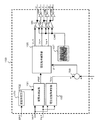
- FIG. 1 is a diagram illustrating a configuration example of a power conversion device according to Embodiment 1 of the present invention.
- the power converter is connected to the overhead line 1 via the current collector 2 and connected to the rail 4 via the wheels 3.
- the overhead line 1 and the rail 4 are connected to a substation (not shown) serving as a DC power source, the current collector 2 receives power from the overhead line 1, and the wheel 3 is connected to the rail 4 as a return circuit for return current. ing.
- the power converter includes an LC filter circuit including a reactor 5 and a capacitor 6 in order to suppress the harmonic current from flowing out to the overhead line 1, a voltage detector 7 that detects the DC voltage EFC of the capacitor 6, and the capacitor 6.
- One end of the power conversion circuit 10 connected in parallel and composed of the upper arm side switching element 11 and the lower arm side switching element 12 is connected to a connection point between the upper arm side switching element 11 and the lower arm side switching element 12, and the current flows.
- a smoothing reactor 20 which is a smoothing filter for performing ripple filtering, a current detector 21 for detecting a current ISL of the smoothing reactor 20, a power storage element 26 serving as a load, a voltage detector 23 for detecting an output voltage BFC, and an LC filter circuit As a control unit to suppress electrical vibration and suppress transient vibration of capacitor voltage And a converter control unit 30.
- the power conversion circuit 10 is a DC-DC conversion circuit (DCDC converter).
- a nickel-metal hydride secondary battery, a lithium ion secondary battery, an electric double layer capacitor, or the like is suitable, but it is not limited and may be other.
- the substation has been described as an example of the DC power source, other DC voltage sources may be used.
- the converter control unit 30 includes a subtractor 31 that receives the current command ISL * of the smoothing reactor 20 and obtains the difference between the smoothing reactor currents ISL, and a current controller 32 that performs proportional-integral control by receiving the output of the subtractor 31.
- An adder 33 that takes the sum of the output of the current controller 32 and the voltage BFC of the power storage element 26 and generates a voltage command VREF as a first output voltage command that is a command of the magnitude of the output voltage in the converted power; Based on the divider 35 for dividing the voltage command VREF by the signal EFC2 which is the first control signal and outputting the duty ratio M which is the second output voltage command, the duty ratio M and the carrier signal CAR.
- a modulation circuit 37 that outputs a switching signal GSG to the power conversion circuit 10.
- the conduction rate M may be generated by adding BFC / EFC2 to the output of the current controller 32.
- the carrier signal CAR is a triangular wave or sawtooth wave carrier having a value of 0 to 1.
- the modulation circuit 37 compares the magnitude relationship between the conduction rate M and the carrier signal CAR, and generates the switching signal GSG based on the comparison result. If the conduction ratio M> the carrier signal CAR, the upper arm side switching element 11 is turned on and the lower arm side switching element 12 is turned off. If the conduction ratio M ⁇ carrier signal CAR, the lower arm side switching element 12 is turned on and the upper arm side switching element 11 is turned off. In this way, control is performed by adjusting the ON time width of the upper arm side switching element 11 and the ON time width of the lower arm side switching element 12.
- the signal EFC2 is a signal obtained by delaying the voltage EFC of the capacitor 6 by the delay processing unit 34.
- the delay processing unit 34 performs, for example, first-order delay processing on the input voltage EFC, and generates and outputs a signal EFC2 that is a first control signal.
- the first embodiment is characterized in that the conduction rate M is generated based on the signal EFC2 generated by the delay processing unit 34.
- the current controller 32 is preferably proportional-integral control, but may be proportional control. Any of them can be configured by a known technique.
- the power conversion device configured as described above converts the voltage ES from the overhead wire 1 into a predetermined voltage value, applies it to both ends of the power storage element 26, and controls on / off of the switching element of the power conversion circuit 10,
- the smoothing reactor current ISL (equal to the current of the power storage element 26) is adjusted to a predetermined current value. That is, the power converter controls the smoothing reactor current ISL to a predetermined current value.
- a smoothing reactor current command ISL * which is a command value of the smoothing reactor current ISL, is output from a higher-level control system (not shown).
- ISL * is set to a positive value.
- an LC filter circuit including the reactor 5 and the capacitor 6 is installed to attenuate the harmonic current flowing out from the power conversion circuit 10 to the overhead wire 1 side. Since this LC filter circuit exists, electric vibration may occur as described below. The principle of the occurrence of electrical vibration in the LC filter circuit will be briefly described below.
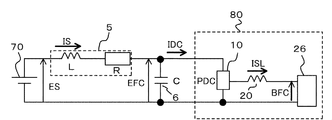
- FIG. 2 is a simplified representation of the system shown in FIG. 1, and is connected to a DC power source 70 simulating the overhead wire 1, and an LC filter composed of a reactor 5 and a capacitor 6 is connected to a power conversion circuit 10 and a smoothing circuit. It is a figure which shows the circuit at the time of connecting the reactor 20 and the electric power storage element 26, and carrying out constant current control of the smoothing reactor current ISL.
- the reactor 5 includes an inductance component L and a resistance component R.
- the capacitance of the capacitor 6 is C.
- the power conversion circuit 10 is controlled so that the smoothing reactor current ISL that is the output of the power conversion circuit is maintained constant even when the voltage EFC of the capacitor 6 fluctuates. Is done. Therefore, the power passing through the power conversion circuit 10 is constant, so that the power conversion circuit 10 has a constant power characteristic with respect to the fluctuation of the voltage EFC of the capacitor 6. That is, even if the voltage EFC varies, the input power PDC of the power conversion circuit 10 is controlled so as not to change. From the above characteristics, an element in which the power conversion circuit 10, the smoothing reactor 20, and the power storage element 26 are collectively expressed as a load of the LC filter is expressed as a constant power load 80.
- the constant power load 80 viewed from the DC power supply 70 side has a negative resistance characteristic.
- the negative resistance characteristic is a characteristic in which the input current IDC of the power conversion circuit 10 decreases if the voltage EFC of the capacitor 6 increases, and the input current IDC of the power conversion circuit 10 increases if the voltage EFC of the capacitor 6 decreases. It is.
- the DC input unit of the system shown in FIG. 2 exhibits negative resistance characteristics, and the input current IDC of the power conversion circuit 10 decreases as the voltage EFC of the capacitor 6 increases.
- the input current IDC of the power conversion circuit 10 increases, so that the operation of promoting the decrease of the voltage EFC of the capacitor 6 is performed. For this reason, braking is not effective for the fluctuation of the voltage EFC of the capacitor 6, the electric vibration of the LC filter circuit expands, and the voltage EFC of the capacitor 6 continuously vibrates in the vicinity of the resonance frequency of the LC filter.
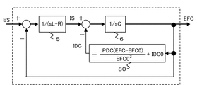
- the phenomenon described above is quantitatively explained by obtaining and evaluating the transfer function of the system of FIG.
- a transfer function from the DC voltage ES to the voltage EFC of the capacitor 6 is obtained.
- the constant power load 80 is controlled so that its output is constant.
- the relational expression of the input power PDC of the power conversion circuit 10, the voltage EFC of the capacitor 6, and the input current IDC of the power conversion circuit 10 is the following expression (1).
- Equation (6) does not contain useful information, it is ignored here. Equation (5) is rewritten as the following equation (7).
- Equation (7) the smaller R, the larger C, the smaller the PDC, and the larger EFC0, the smaller the R required for the system to stabilize.
- the resistance component existing on the direct current side is as small as several tens of m ⁇ , and it is difficult to satisfy the equation (7). As a result, the system becomes unstable and the LC filter circuit generates vibration.
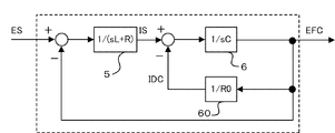
- FIG. 4 is a diagram showing a circuit in which a load composed of a resistor 60 is connected to the LC filter circuit connected to the DC power supply 70. As compared with the circuit shown in FIG. 2, the constant power load 80 is replaced with a resistor 60. The resistance value of the resistor 60 is R0.
- FIG. 5 is a diagram showing a transfer function block of the system of FIG. From FIG. 5, the closed loop transfer function Gp (s) from the voltage Es of the DC power supply 70 to the voltage EFC of the capacitor 6 is expressed by the following equation (8).
- R ⁇ 0 is obtained by calculating a condition in which all the solutions of the characteristic equation represented by Expression (9) are negative, and this condition is always satisfied. From this, it can be seen that when the load is composed of the resistor 60, the load is always stable. As described above, it can be seen that the circuit in which the resistor 60 is connected to the LC filter circuit connected to the DC power supply 70 is always stable.
- the voltage of the overhead wire 1 (overhead voltage ES) may fluctuate rapidly depending on the operating state of other electric vehicles that are supplied with power from the same overhead wire 1.
- the voltage EFC of the capacitor 6 generates a transient vibration. If the suppression of the transient vibration is insufficient, the capacitor 6 becomes overvoltage, and the power converter may stop. Therefore, it is important to suppress the transient vibration of the voltage EFC of the capacitor 6 when the overhead wire voltage ES fluctuates rapidly.
- the voltage EFC of the capacitor 6 is delayed by the delay processing unit 34 to obtain the signal EFC2 that is the first control signal. Based on this signal EFC2 and VREF which is the first output voltage command, the current flow rate M is generated.
- the conduction ratio M is generated based on the signal EFC2 delayed from the voltage EFC. It will be.
- the conduction ratio M immediately decreases in inverse proportion to the increase in the voltage EFC and is corrected to a predetermined value corresponding to the voltage EFC, thereby canceling the fluctuation in the voltage EFC.
- the output of the power conversion circuit 10 is adjusted so as not to fluctuate due to the fluctuation of the voltage EFC.
- a transient fluctuation of the output of the power conversion circuit 10 due to the fluctuation of the voltage EFC is allowed to some extent, and the conduction ratio M decreases to a predetermined value corresponding to the voltage EFC with a certain delay. It becomes a behavior.
- the constant power characteristic of the power conversion circuit 10 with respect to the fluctuation of the voltage EFC can be weakened, and the negative resistance characteristic described above can be weakened, so that the system can be stabilized and the transient oscillation of the voltage EFC Can also be suppressed.
- FIG. 6 is a diagram illustrating a waveform example of the voltage EFC as the input capacitor voltage in the first embodiment.
- the overhead line voltage ES is 1400 V in a state where power is supplied from the overhead line 1 side to the power storage element 26 side and the power storage element 26 is charged. Between 1600V is changed in steps.
- the upper part is a waveform example when there is no delay processing unit as a comparative example, and the lower part is a waveform example when the delay processing unit 34 is applied. As shown in FIG.
- the delay process in the delay processing unit 34 is preferably a first-order delay process.
- the first-order lag time constant When the first-order lag time constant is reduced, the effect of suppressing the transient fluctuation of the voltage EFC when the overhead wire voltage fluctuates decreases.
- the first-order lag time constant When the first-order lag time constant is increased, the effect of suppressing the transient fluctuation of the voltage EFC is increased.
- this first-order lag time constant must be set appropriately.
- the first-order lag time constant is preferably 10 ms to 800 ms, preferably 50 ms to 200 ms is more preferable.
- the reactor 5 is 10 mH
- the capacitor 6 is 3000 ⁇ F
- the delay processing of the delay processing unit 34 is first-order lag processing
- the first-order lag time constant is 200 ms.
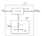
- the delay processing unit 34 generates a signal EFC2 based on the input voltage EFC and outputs the signal EFC2, and a primary delay time constant set in the primary delay calculation unit 341.
- the time constant generation unit 342a Based on the voltage EFC, the time constant generation unit 342a has a first-order lag time constant T when the voltage EFC is higher than a predetermined value and a smaller value than the first-order lag time constant T when the voltage EFC is lower than a predetermined value. It is preferable that the configuration is generated so that
- the first-order lag time constant T may be generated based on the overhead wire voltage ES instead of the voltage EFC.
- the first-order lag time constant T can be set small under conditions where the negative resistance characteristic of the system becomes weak, so that transient fluctuations in the output of the power conversion circuit 10 accompanying fluctuations in the overhead line voltage ES are minimized.
- the system can be stabilized and the transient oscillation of the voltage EFC can be suppressed.
- a first-order lag calculator 341 that generates and outputs a signal EFC2 based on the input voltage EFC, and a first-order lag time constant T set in the first-order lag calculator 341,
- the delay processing unit 34 may be configured from a time constant generation unit 342b that receives the input power PDC and generates the input power PDC based on the input power PDC.
- the time constant generation unit 342b Based on the input power PDC, the time constant generation unit 342b has a primary delay time constant T when the input power PDC is smaller than a predetermined value, that is, when the converted power of the power conversion circuit 10 is small, and the input power PDC is a predetermined value. It is preferable that the first delay time constant T is generated to be smaller than the first delay time constant T.
- the first-order lag time constant T is based on, for example, the input current IS or the current or power passing through the power conversion circuit 10, the output current ISL, the output power, or the like (generically referred to as load amount) in addition to the input power PDC.
- load amount the input current IS or the current or power passing through the power conversion circuit 10
- a generated configuration may be used.
- the first-order lag time constant T can be set small under conditions where the negative resistance characteristic of the system is weak or when the system is stable, so that transient fluctuations in the output of the power conversion circuit 10 accompanying fluctuations in the overhead wire voltage ES are achieved. It is possible to stabilize the system and suppress the transient oscillation of the voltage EFC while minimizing the noise.
- the converter control unit 30 by providing the converter control unit 30 with the delay processing unit 34, electric vibration of the LC filter circuit of the DCDC converter which is the power conversion circuit 10 can be suppressed, and the capacitor Transient vibration of voltage EFC can be suppressed. For this reason, even when the voltage of the DC power supply such as the overhead line voltage fluctuates abruptly, the capacitor 6 can be prevented from being overvoltage, and the normal operation of the power converter can be maintained.
- Embodiment 2 FIG.
- the power conversion circuit 10 is a DCDC converter, but in the second embodiment, a DC-AC conversion circuit (inverter) is described. Even in the configuration in which the motor is driven and controlled by the DC-AC converter circuit, negative resistance characteristics are generated on the input side of the power converter circuit based on the principle described in the first embodiment.
- FIG. 9 is a diagram illustrating a configuration of the power conversion device according to the second embodiment.
- the power converter is connected to the overhead line 1 via the current collector 2 and connected to the rail 4 via the wheels 3.
- the overhead line 1 and the rail 4 are connected to a substation (not shown) serving as a DC power source, the current collector 2 receives power from the overhead line 1, and the wheel 3 is connected to the rail 4 as a return circuit for return current. ing.
- the power conversion device includes an inverter 104 as a power conversion circuit that converts a DC voltage into an AC voltage of an arbitrary frequency, and a reactor 102 and a capacitor 103 in order to suppress a harmonic current from the inverter 104 from flowing out to the power supply side. And an inverter control unit 180 as a control unit that controls the inverter 4 that converts the voltage EFC of the capacitor 103 into an AC voltage.
- the inverter control unit 180 receives a signal from the speed detector 107 that detects the rotation speed of the electric motor 106, a signal from the current detectors 105a to 105c that detects current, and the voltage EFC of the capacitor 103, and an external control device ( (Not shown), a torque command Tm * is input, and the torque Tm generated by the electric motor 106 is controlled to coincide with the torque command Tm *.
- the current detector is not limited to being provided in three phases, but may be provided in two phases and calculating the remaining one phase.
- the speed sensorless control method that calculates and calculates the rotational speed of the electric motor 106 without providing the speed detector 107 has been put into practical use, the speed detector 107 becomes unnecessary in that case.
- the inverter control unit 180 controls the motor on a dq-axis rotational coordinate system in which an axis coinciding with the secondary magnetic flux axis of the electric motor 106 is defined as a d-axis and an axis orthogonal to the d-axis is defined as a q-axis. This is a configuration for performing vector control.
- M is a mutual inductance
- l2 is a secondary leakage inductance
- s is a differential operator
- PP is the number of pole pairs of the electric motor 106
- R2 is a secondary resistance of the electric motor 106.
- the slip angular frequency command generation unit 119 determines the slip angular frequency command ⁇ s to be given to the motor 106 from the following equation (12) from the d-axis current command Id *, the q-axis current command Iq *, and the circuit constants of the motor 106. * Is calculated.
- R2 represents the secondary resistance of the electric motor.
- the slip angular frequency command ⁇ s * calculated by the equation (12) and the rotational angular frequency ⁇ r output from the speed detector 107 attached to the shaft end of the motor 106 are added by the adder 121, and the inverter 104 outputs the result.
- Inverter angular frequency ⁇ The result obtained by integrating the inverter angular frequency ⁇ by the integrator 122 is input to the voltage command / PWM signal generation unit 150 (described later) and the three-phase-dq axis coordinate converter 123 as a basic phase angle ⁇ of coordinate conversion.
- the U-phase current Iu, V-phase current Iv, and W-phase current Iw detected by the current detectors 105a to 105c are calculated on the dq coordinate calculated by the following equation (13). Conversion into d-axis current Id and q-axis current Iq.
- the subtractor 110 calculates the difference between the q-axis current command Iq * and the q-axis current Iq, and inputs the result to the q-axis current controller 112 in the next stage.
- the q-axis current controller 112 performs proportional-integral control on the input value and outputs a q-axis voltage compensation value qe.
- the subtractor 111 calculates the difference between the d-axis current command Id * and the q-axis current Iq, and inputs the result to the d-axis current controller 113 in the next stage.
- the d-axis current controller 113 performs proportional-integral control on the input value and outputs a d-axis voltage compensation value de.
- the q-axis current error qe and the d-axis current error de are expressed by the following equations (14) and (15). In the following equation, s is a differential operator, K1 is a proportional gain, and K2 is an integral gain.
- the voltage non-interference calculation unit 114 calculates the d-axis feed according to the following equations (16) and (17) from the d-axis current command Id *, the q-axis current command Iq *, and the circuit constants of the motor 106.
- the forward voltage Ed * and the q-axis feedforward voltage Eq * are calculated.
- R1 is the primary resistance of the motor 106
- the adder 117 adds the q-axis voltage compensation value qe and the q-axis feedforward voltage Eq * to the q-axis voltage command Vq *, and the adder 118 uses the d-axis voltage compensation value de and the d-axis feed.
- the sum of the forward voltage Ed * is input to the voltage command / PWM signal generator 150 as the d-axis voltage command Vd *.
- the q-axis voltage command Vq * and the d-axis voltage command Vd * are expressed by the following equations (18) and (19).
- the inverter output voltage command VM * which is the first output voltage command, is expressed by the following equation (20).
- VM * represents the magnitude of the inverter output voltage command vector.
- the inverter 104 is a voltage-type PWM inverter that is already known, and a detailed description of the configuration is omitted.
- the switching elements U, V, and W are the U phase of the upper arm of the inverter 104
- the switching elements are arranged in the V phase and the W phase
- the switching elements X, Y, and Z are switching elements arranged in the U phase, the V phase, and the W phase of the lower arm of the inverter 104.
- FIG. 10 is a diagram illustrating a configuration example of the voltage command / PWM signal generation unit 150 in the second embodiment.
- the delay processing unit 170 receives the capacitor voltage EFC and outputs a signal EFC2.
- the modulation factor calculator 151 calculates a modulation factor PMF, which is a command for the magnitude of the AC output voltage and a second output voltage command, from the signal EFC2, the q-axis voltage command Vq *, and the d-axis voltage command Vd *.
- the voltage phase angle calculation unit 152 calculates a voltage phase angle THV that is a voltage phase command of the AC output voltage from the q-axis voltage command Vq * and the d-axis voltage command Vd *.
- the modulation factor PMF indicates the inverter output voltage command VM * as a percentage of the maximum voltage VMmax that can be output by the inverter.
- PMF 1.0
- the inverter output voltage command VM * is the inverter output voltage. It is shown that it becomes equal to the maximum value VMmax.
- the modulation factor calculation unit 151 and the voltage phase angle calculation unit 152 perform the following calculations (21) and (22), respectively.
- the maximum value VMmax of the inverter output voltage VM is calculated by the following equation (23) based on the signal EFC2.
- VMmax is the maximum voltage that the inverter 104 can output when the value of the voltage EFC of the capacitor 103 is equal to the value of the signal EFC2, and is a value when the inverter 104 is operated in a one-pulse mode in which rectangular wave conduction is performed. is there.
- the signal EFC2 is a signal obtained by delaying the capacitor voltage EFC by the delay processing unit 170. That is, the delay processing unit 170 performs, for example, first-order delay processing on the input voltage EFC, and generates and outputs a signal EFC2 that is a first control signal.
- the second embodiment is characterized in that a modulation factor PMF, which is a second output voltage command, is generated based on the signal EFC2 generated by the delay processing unit 170.
- the adder 156 generates the control phase angle ⁇ 1 by taking the sum of the voltage phase angle THV and the basic phase angle ⁇ , and the control phase angle ⁇ 1 is input to the voltage command calculation unit 155.
- the modulation factor PMF is also input to the voltage command calculation unit 155.
- the U-phase voltage command Vu * and V-phase which are three-phase output voltage commands, are calculated from the modulation factor PMF and the control phase angle ⁇ 1 using the following formulas (24) to (26).
- a voltage command Vv * and a W-phase voltage command Vw * are generated.
- the U-phase voltage command Vu *, V-phase voltage command Vv *, and W-phase voltage command Vw * are respectively compared with the carrier signal CAR by the comparators 161 to 163 to generate gate signals U, V, and W.
- the U-phase voltage command Vu *, the V-phase voltage command Vv *, and the W-phase voltage command Vw * are compared with the carrier signal CAR by the comparators 161 to 163, and then passed through the inverting circuits 164 to 166, and then gated.
- Signals X, Y, Z are generated.
- the carrier signal CAR is a triangular wave carrier signal generated by the carrier signal generator 157.
- both the modulation factor PMF and the voltage phase THV are signals generated based on the q-axis voltage command Vq * and the d-axis voltage command Vd *, but the signal generated including the signal EFC2 is the modulation factor as described above. Limited to PMF.
- the voltage phase angle THV is generated only from the q-axis voltage command Vq * and the d-axis voltage command Vd *, and is not adjusted based on the signal EFC2. Incidentally, it has been confirmed that the control performance of the electric motor 106 is significantly deteriorated by the method of adjusting the voltage phase angle THV based on the signal EFC2.
- the inverter output voltage command VM * which is the first output voltage command, is calculated from the q-axis voltage command Vq * and the d-axis voltage command Vd *, and the inverter output voltage command VM * and the signal From the EFC2, a configuration for calculating the modulation factor PMF, which is a command for the magnitude of the AC output voltage and the second output voltage command, and the AC output voltage from the q-axis voltage command Vq * and the d-axis voltage command Vd *.
- the voltage phase angle THV which is a voltage phase command, is calculated, and the three-phase output voltage commands Vu *, Vv *, Vw * are generated based on the calculated modulation factor PMF and the voltage phase angle THV.
- the modulation factor PMF is generated based on the signal EFC2 delayed from the voltage EFC.
- the modulation factor PMF decreases immediately in inverse proportion to the increase in the voltage EFC and is corrected to a predetermined value according to the voltage EFC, thereby canceling the fluctuation in the voltage EFC. Adjustment is made so that fluctuations in voltage EFC do not affect the output of power conversion circuit 104.
- transient fluctuation of the output of the power conversion circuit 104 due to fluctuation of the voltage EFC is allowed to some extent, and the modulation factor PMF decreases to a predetermined value according to the voltage EFC with a certain delay. It becomes.
- the constant power characteristic of the power conversion circuit 104 with respect to the fluctuation of the voltage EFC can be weakened, and the above-described negative resistance characteristic can be weakened. Therefore, the system can be stabilized and the transient vibration of the voltage EFC can be suppressed.
- the delay process in the delay processing unit 170 is preferably a first-order delay process.
- the first-order lag time constant When the first-order lag time constant is reduced, the effect of suppressing the transient fluctuation of the voltage EFC when the overhead wire voltage fluctuates decreases.
- the first-order lag time constant When the first-order lag time constant is increased, the effect of suppressing the transient fluctuation of the voltage EFC is increased.
- this first-order lag time constant must be set appropriately.
- the first-order lag time constant is preferably 10 ms to 800 ms, preferably 50 ms to 200 ms is more preferable.
- the higher the voltage EFC and the smaller the input power PDC the weaker the negative resistance characteristics.
- the input power PDC is negative, the system is always stable.
- the delay processing unit 170 preferably has the same internal configuration as the delay processing unit 34 described in the first embodiment. That is, the delay processing unit 170 of the second embodiment is the same as the configuration of FIGS. 7 and 8 described in the first embodiment, and the description thereof is omitted.
- the time constant generation unit 342 b When the delay processing unit 170 has the configuration shown in FIG. 8, the time constant generation unit 342 b generates, for example, the input current IS or the power conversion circuit 104 in addition to the configuration that generates the first-order lag time constant T based on the input power PDC. It is good also as a structure produced
- the first-order lag time constant T can be set small under conditions where the negative resistance characteristic of the system is weak or when the system is stable, and therefore, transient fluctuations in the output of the power conversion circuit 104 accompanying fluctuations in the overhead wire voltage ES. It is possible to stabilize the system and suppress the transient oscillation of the voltage EFC while minimizing the noise.
- the delay control unit 170 is provided in the voltage command / PWM signal generation unit 150 of the inverter control unit 180, so that the LC filter circuit of the inverter that is the power conversion circuit 104.
- the electrical vibration of the capacitor can be suppressed, and the transient vibration of the capacitor voltage can be suppressed. For this reason, even when the voltage of the DC power supply such as the overhead line voltage fluctuates abruptly, the capacitor 6 can be prevented from being overvoltage, and the normal operation of the power converter can be maintained.
- the present invention can also be applied to a case of a synchronous motor other than this.
- the example of the substation connected to the overhead line 1 was shown as DC power supply, a storage battery and a generator can be applied similarly as DC power supply.
- the configurations shown in the first and second embodiments are examples of the contents of the present invention, and it is needless to say that the configurations can be modified without departing from the gist of the present invention.
- Reactor 6 Capacitor 10 Power conversion circuit (DCDC converter) 30 Converter Control Unit 34 Delay Processing Unit 102 Reactor 103 Capacitor 104 Power Conversion Circuit (Inverter) 150 Voltage command / PWM signal generation unit 170 Delay processing unit 180 Inverter control unit 341 First order delay calculation units 342a, 342b Time constant generation unit
Abstract
Description
実施の形態1について図面を参照して説明する。図1は、本発明の実施の形態1における電力変換装置の構成例を示す図である。電力変換装置は、集電装置2を介して架線1に接続されるとともに、車輪3を介してレール4に接続されている。架線1及びレール4は直流電源となる変電所(図示せず)に接続されており、集電装置2は架線1から電力を受電し、車輪3はリターン電流の戻り回路としてレール4に接続されている。


電力変換回路10として、実施の形態1ではDCDCコンバータとした場合を説明したが、実施の形態2では直流-交流変換回路(インバータ)である場合を説明する。直流-交流変換回路により電動機を駆動制御する構成においても、電力変換回路の入力側には、実施の形態1で説明した原理に基づいて負抵抗特性が生じる。


6 コンデンサ
10 電力変換回路(DCDCコンバータ)
30 コンバータ制御部
34 遅延処理部
102 リアクトル
103 コンデンサ
104 電力変換回路(インバータ)
150 電圧指令/PWM信号生成部
170 遅延処理部
180 インバータ制御部
341 一次遅れ演算部
342a、342b 時定数生成部
Claims (7)
- 架線から電力を受電し、リアクトルとコンデンサとからなるLCフィルタ回路を介して前記架線からの電力を変換した変換電力を出力する電力変換回路と、前記電力変換回路を制御する制御部とを有する電力変換装置において、
前記制御部は、時定数を生成する時定数生成部と前記時定数に基づき前記コンデンサの電圧を遅延処理して第一の制御信号を生成する演算部とからなる遅延処理部を備え、前記変換電力における出力電圧の大きさの指令である第一の出力電圧指令と前記第一の制御信号とから第二の出力電圧指令を生成し、前記第二の出力電圧指令に基づいて前記電力変換回路を制御することを特徴とする電力変換装置。 - 時定数生成部は、電力変換回路の状態量に応じて時定数を生成することを特徴とする請求項1に記載の電力変換装置。
- 電力変換回路の状態量は、入力側電圧であることを特徴とする請求項2に記載の電力変換装置。
- 電力変換回路の状態量は、負荷量であることを特徴とする請求項2に記載の電力変換装置。
- 遅延処理部は、入力側電圧が所定値よりも高いときは、入力側電圧が所定値よりも低いときと比べて小さい時定数を生成することを特徴とする請求項3に記載の電力変換装置。
- 遅延処理部は、負荷量が所定値よりも小さいときは、負荷量が所定値よりも大きいときと比べて小さい時定数を生成することを特徴とする請求項4に記載の電力変換装置。
- 電力変換回路は、直流を入力として交流を出力するインバータであり、制御部は、前記インバータが出力する交流電力における交流出力電圧の大きさの指令である第一の出力電圧指令を生成し、前記第一の出力電圧指令と前記第一の制御信号とから第二の出力電圧指令を生成し、前記交流出力電圧の電圧位相の指令である電圧位相角を生成し、前記第二の出力電圧指令と前記電圧位相角とに基づいて、前記インバータを制御することを特徴とする請求項1乃至請求項6のいずれか一項に記載の電力変換装置。
Priority Applications (4)
| Application Number | Priority Date | Filing Date | Title |
|---|---|---|---|
| CN201080043334.7A CN102511122B (zh) | 2009-09-29 | 2010-09-28 | 电力变换装置 |
| EP10820115.3A EP2472710B1 (en) | 2009-09-29 | 2010-09-28 | Power conversion device |
| JP2011528105A JP4835812B2 (ja) | 2009-09-29 | 2010-09-28 | 電力変換装置 |
| US13/387,873 US8593843B2 (en) | 2009-09-29 | 2010-09-28 | Electric power conversion device capable of suppressing electric oscillations |
Applications Claiming Priority (2)
| Application Number | Priority Date | Filing Date | Title |
|---|---|---|---|
| JPPCT/JP2009/004961 | 2009-09-29 | ||
| PCT/JP2009/004961 WO2011039794A1 (ja) | 2009-09-29 | 2009-09-29 | 電力変換装置 |
Publications (1)
| Publication Number | Publication Date |
|---|---|
| WO2011039993A1 true WO2011039993A1 (ja) | 2011-04-07 |
Family
ID=43825652
Family Applications (2)
| Application Number | Title | Priority Date | Filing Date |
|---|---|---|---|
| PCT/JP2009/004961 WO2011039794A1 (ja) | 2009-09-29 | 2009-09-29 | 電力変換装置 |
| PCT/JP2010/005811 WO2011039993A1 (ja) | 2009-09-29 | 2010-09-28 | 電力変換装置 |
Family Applications Before (1)
| Application Number | Title | Priority Date | Filing Date |
|---|---|---|---|
| PCT/JP2009/004961 WO2011039794A1 (ja) | 2009-09-29 | 2009-09-29 | 電力変換装置 |
Country Status (4)
| Country | Link |
|---|---|
| US (1) | US8593843B2 (ja) |
| EP (1) | EP2472710B1 (ja) |
| CN (1) | CN102511122B (ja) |
| WO (2) | WO2011039794A1 (ja) |
Cited By (2)
| Publication number | Priority date | Publication date | Assignee | Title |
|---|---|---|---|---|
| JP2019201504A (ja) * | 2018-05-17 | 2019-11-21 | 株式会社日立製作所 | モータ制御装置および同装置の制御方法 |
| WO2022264257A1 (ja) * | 2021-06-15 | 2022-12-22 | 三菱電機株式会社 | 電源装置 |
Families Citing this family (11)
| Publication number | Priority date | Publication date | Assignee | Title |
|---|---|---|---|---|
| DK2575252T3 (en) | 2011-09-29 | 2018-10-08 | Daihen Corp | Signal processor, filter, power converter for power converter circuit, connection inverter system and PWM inverter system |
| CN103036529B (zh) * | 2011-09-29 | 2017-07-07 | 株式会社大亨 | 信号处理装置、滤波器、控制电路、逆变器和转换器系统 |
| TWI506959B (zh) * | 2012-12-18 | 2015-11-01 | Ind Tech Res Inst | 調變方法以及應用該調變方法之控制裝置 |
| JP2015116092A (ja) * | 2013-12-13 | 2015-06-22 | トヨタ自動車株式会社 | 電動車両 |
| EP2940824B1 (en) * | 2014-04-29 | 2022-11-23 | General Electric Technology GmbH | Improvements in or relating to voltage source converters |
| CN104192014B (zh) * | 2014-09-05 | 2016-05-04 | 江苏今创车辆有限公司 | 采用统一电压输出及双向dc/dc模块的双能源机车 |
| KR102499262B1 (ko) * | 2015-10-14 | 2023-02-13 | 삼성전자주식회사 | 액티브 필터 및 그 제어방법, 액티브 필터를 포함하는 전력 관리 시스템 |
| CN105634272A (zh) * | 2016-01-27 | 2016-06-01 | 姚安宇 | 主板供电电路 |
| SE541627C2 (en) | 2018-03-20 | 2019-11-19 | Bombardier Transp Gmbh | A system and a method for feeding electric power to a consumer thereof |
| CN109713895B (zh) * | 2018-12-26 | 2021-02-02 | 上海南芯半导体科技有限公司 | 一种用于dc-dc中恒流恒功率控制电路及实现方法 |
| WO2023188667A1 (ja) * | 2022-03-30 | 2023-10-05 | 株式会社日立製作所 | 車両用駆動制御装置及びその方法 |
Citations (5)
| Publication number | Priority date | Publication date | Assignee | Title |
|---|---|---|---|---|
| JPH02211002A (ja) * | 1989-02-07 | 1990-08-22 | Hitachi Ltd | 電気車用発電ブレーキ装置 |
| JPH0398402A (ja) * | 1989-09-11 | 1991-04-24 | Toshiba Corp | 車両用電力変換装置 |
| JPH11299012A (ja) * | 1998-02-12 | 1999-10-29 | Mitsubishi Electric Corp | 直流電気車の制御装置 |
| JP2000116189A (ja) * | 1998-10-08 | 2000-04-21 | Mitsubishi Electric Corp | 誘導電動機の制御装置 |
| JP2003199204A (ja) | 2001-12-25 | 2003-07-11 | Toshiba Corp | 電気車制御装置 |
Family Cites Families (8)
| Publication number | Priority date | Publication date | Assignee | Title |
|---|---|---|---|---|
| US5077652A (en) * | 1990-10-18 | 1991-12-31 | Dynamote Corporation | Dual feedback loop DC-to-AC converter |
| JPH0583976A (ja) * | 1991-09-18 | 1993-04-02 | Hitachi Ltd | 交流電動機制御装置及びこれを用いた電気車の制御装置 |
| US7479769B2 (en) * | 2003-08-29 | 2009-01-20 | Nxp B.V. | Power delivery system having cascaded buck stages |
| JP4980588B2 (ja) * | 2005-06-21 | 2012-07-18 | ローム株式会社 | 降圧型スイッチングレギュレータ、その制御回路、ならびにそれを用いた電子機器 |
| JP4065901B1 (ja) * | 2006-08-29 | 2008-03-26 | 三菱電機株式会社 | 交流電動機のベクトル制御装置 |
| WO2008053554A1 (en) * | 2006-11-02 | 2008-05-08 | Mitsubishi Electric Corporation | Electric motor car control apparatus |
| EP2642658B1 (en) * | 2007-09-25 | 2018-08-29 | Mitsubishi Electric Corporation | Controller for electric motor |
| CA2714211C (en) * | 2008-02-13 | 2015-06-30 | Masaki Kono | Electrical power conversion apparatus |
-
2009
- 2009-09-29 WO PCT/JP2009/004961 patent/WO2011039794A1/ja active Application Filing
-
2010
- 2010-09-28 EP EP10820115.3A patent/EP2472710B1/en active Active
- 2010-09-28 WO PCT/JP2010/005811 patent/WO2011039993A1/ja active Application Filing
- 2010-09-28 CN CN201080043334.7A patent/CN102511122B/zh active Active
- 2010-09-28 US US13/387,873 patent/US8593843B2/en not_active Expired - Fee Related
Patent Citations (5)
| Publication number | Priority date | Publication date | Assignee | Title |
|---|---|---|---|---|
| JPH02211002A (ja) * | 1989-02-07 | 1990-08-22 | Hitachi Ltd | 電気車用発電ブレーキ装置 |
| JPH0398402A (ja) * | 1989-09-11 | 1991-04-24 | Toshiba Corp | 車両用電力変換装置 |
| JPH11299012A (ja) * | 1998-02-12 | 1999-10-29 | Mitsubishi Electric Corp | 直流電気車の制御装置 |
| JP2000116189A (ja) * | 1998-10-08 | 2000-04-21 | Mitsubishi Electric Corp | 誘導電動機の制御装置 |
| JP2003199204A (ja) | 2001-12-25 | 2003-07-11 | Toshiba Corp | 電気車制御装置 |
Non-Patent Citations (1)
| Title |
|---|
| See also references of EP2472710A4 * |
Cited By (4)
| Publication number | Priority date | Publication date | Assignee | Title |
|---|---|---|---|---|
| JP2019201504A (ja) * | 2018-05-17 | 2019-11-21 | 株式会社日立製作所 | モータ制御装置および同装置の制御方法 |
| JP7100494B2 (ja) | 2018-05-17 | 2022-07-13 | 株式会社日立製作所 | モータ制御装置および同装置の制御方法 |
| WO2022264257A1 (ja) * | 2021-06-15 | 2022-12-22 | 三菱電機株式会社 | 電源装置 |
| JP7374387B2 (ja) | 2021-06-15 | 2023-11-06 | 三菱電機株式会社 | 電源装置 |
Also Published As
| Publication number | Publication date |
|---|---|
| EP2472710B1 (en) | 2016-01-13 |
| EP2472710A4 (en) | 2014-10-01 |
| WO2011039794A1 (ja) | 2011-04-07 |
| US8593843B2 (en) | 2013-11-26 |
| US20120147638A1 (en) | 2012-06-14 |
| CN102511122B (zh) | 2015-01-21 |
| CN102511122A (zh) | 2012-06-20 |
| EP2472710A1 (en) | 2012-07-04 |
Similar Documents
| Publication | Publication Date | Title |
|---|---|---|
| WO2011039993A1 (ja) | 電力変換装置 | |
| EP2380272B1 (en) | Control system for ac motor | |
| JP5120670B2 (ja) | 電動機駆動装置の制御装置 | |
| JP5120669B2 (ja) | 電動機駆動装置の制御装置 | |
| CA2660601C (en) | Vector control device for alternating-current electric motor | |
| JP4706324B2 (ja) | モータ駆動システムの制御装置 | |
| JP5246508B2 (ja) | 電動機駆動装置の制御装置 | |
| US7595600B2 (en) | Method and system for torque control in permanent magnet machines | |
| US7282886B1 (en) | Method and system for controlling permanent magnet motor drive systems | |
| EP2621079B1 (en) | Inverter control device and inverter control method | |
| WO2012144000A1 (ja) | 交流電動機の制御装置 | |
| JP5354036B2 (ja) | 車両および車両の制御方法 | |
| JP2011067010A (ja) | 車両のモータ駆動装置 | |
| JP4835812B2 (ja) | 電力変換装置 | |
| JP6627702B2 (ja) | 電力変換器の制御装置 | |
| US8975839B2 (en) | Vehicle, and control method for vehicle | |
| JP2015126607A (ja) | モータ制御システム | |
| JP5370748B2 (ja) | 電動機駆動装置の制御装置 | |
| WO2023162860A1 (ja) | 交流電動機の制御装置およびプログラム | |
| WO2023176484A1 (ja) | モータ駆動システム、及びモータ駆動プログラム | |
| JP2015162940A (ja) | 電力変換器の制御装置 | |
| JP2010226780A (ja) | 交流電動機の制御システム | |
| JPH10257797A (ja) | 電力変換器のフィードバック制御システム |
Legal Events
| Date | Code | Title | Description |
|---|---|---|---|
| WWE | Wipo information: entry into national phase |
Ref document number: 201080043334.7 Country of ref document: CN |
|
| 121 | Ep: the epo has been informed by wipo that ep was designated in this application |
Ref document number: 10820115 Country of ref document: EP Kind code of ref document: A1 |
|
| WWE | Wipo information: entry into national phase |
Ref document number: 2011528105 Country of ref document: JP |
|
| WWE | Wipo information: entry into national phase |
Ref document number: 13387873 Country of ref document: US |
|
| WWE | Wipo information: entry into national phase |
Ref document number: 2010820115 Country of ref document: EP |
|
| NENP | Non-entry into the national phase |
Ref country code: DE |
|
| WWE | Wipo information: entry into national phase |
Ref document number: 4763/CHENP/2012 Country of ref document: IN |
|
| WWE | Wipo information: entry into national phase |
Ref document number: 5740/CHENP/2012 Country of ref document: IN |