EP2940824B1 - Improvements in or relating to voltage source converters - Google Patents
Improvements in or relating to voltage source converters Download PDFInfo
- Publication number
- EP2940824B1 EP2940824B1 EP14275095.9A EP14275095A EP2940824B1 EP 2940824 B1 EP2940824 B1 EP 2940824B1 EP 14275095 A EP14275095 A EP 14275095A EP 2940824 B1 EP2940824 B1 EP 2940824B1
- Authority
- EP
- European Patent Office
- Prior art keywords
- voltage source
- source converter
- side voltage
- wind farm
- controller
- Prior art date
- Legal status (The legal status is an assumption and is not a legal conclusion. Google has not performed a legal analysis and makes no representation as to the accuracy of the status listed.)
- Active
Links
- 230000005540 biological transmission Effects 0.000 claims description 55
- 230000004044 response Effects 0.000 claims description 7
- 230000008878 coupling Effects 0.000 description 15
- 238000010168 coupling process Methods 0.000 description 15
- 238000005859 coupling reaction Methods 0.000 description 15
- 230000008859 change Effects 0.000 description 5
- 239000004065 semiconductor Substances 0.000 description 5
- 238000012546 transfer Methods 0.000 description 5
- 239000003990 capacitor Substances 0.000 description 4
- 238000006243 chemical reaction Methods 0.000 description 3
- 230000000694 effects Effects 0.000 description 3
- 230000004075 alteration Effects 0.000 description 1
- 238000013459 approach Methods 0.000 description 1
- 238000004891 communication Methods 0.000 description 1
- 238000004146 energy storage Methods 0.000 description 1
- 238000003780 insertion Methods 0.000 description 1
- 230000037431 insertion Effects 0.000 description 1
- 230000004048 modification Effects 0.000 description 1
- 238000012986 modification Methods 0.000 description 1
- 230000009467 reduction Effects 0.000 description 1
- 238000000926 separation method Methods 0.000 description 1
Images


Classifications
-
- H—ELECTRICITY
- H02—GENERATION; CONVERSION OR DISTRIBUTION OF ELECTRIC POWER
- H02J—CIRCUIT ARRANGEMENTS OR SYSTEMS FOR SUPPLYING OR DISTRIBUTING ELECTRIC POWER; SYSTEMS FOR STORING ELECTRIC ENERGY
- H02J3/00—Circuit arrangements for ac mains or ac distribution networks
- H02J3/38—Arrangements for parallely feeding a single network by two or more generators, converters or transformers
- H02J3/381—Dispersed generators
-
- H—ELECTRICITY
- H02—GENERATION; CONVERSION OR DISTRIBUTION OF ELECTRIC POWER
- H02P—CONTROL OR REGULATION OF ELECTRIC MOTORS, ELECTRIC GENERATORS OR DYNAMO-ELECTRIC CONVERTERS; CONTROLLING TRANSFORMERS, REACTORS OR CHOKE COILS
- H02P9/00—Arrangements for controlling electric generators for the purpose of obtaining a desired output
- H02P9/10—Control effected upon generator excitation circuit to reduce harmful effects of overloads or transients, e.g. sudden application of load, sudden removal of load, sudden change of load
- H02P9/102—Control effected upon generator excitation circuit to reduce harmful effects of overloads or transients, e.g. sudden application of load, sudden removal of load, sudden change of load for limiting effects of transients
-
- H—ELECTRICITY
- H02—GENERATION; CONVERSION OR DISTRIBUTION OF ELECTRIC POWER
- H02J—CIRCUIT ARRANGEMENTS OR SYSTEMS FOR SUPPLYING OR DISTRIBUTING ELECTRIC POWER; SYSTEMS FOR STORING ELECTRIC ENERGY
- H02J5/00—Circuit arrangements for transfer of electric power between ac networks and dc networks
-
- H—ELECTRICITY
- H02—GENERATION; CONVERSION OR DISTRIBUTION OF ELECTRIC POWER
- H02M—APPARATUS FOR CONVERSION BETWEEN AC AND AC, BETWEEN AC AND DC, OR BETWEEN DC AND DC, AND FOR USE WITH MAINS OR SIMILAR POWER SUPPLY SYSTEMS; CONVERSION OF DC OR AC INPUT POWER INTO SURGE OUTPUT POWER; CONTROL OR REGULATION THEREOF
- H02M5/00—Conversion of ac power input into ac power output, e.g. for change of voltage, for change of frequency, for change of number of phases
- H02M5/40—Conversion of ac power input into ac power output, e.g. for change of voltage, for change of frequency, for change of number of phases with intermediate conversion into dc
-
- H—ELECTRICITY
- H02—GENERATION; CONVERSION OR DISTRIBUTION OF ELECTRIC POWER
- H02M—APPARATUS FOR CONVERSION BETWEEN AC AND AC, BETWEEN AC AND DC, OR BETWEEN DC AND DC, AND FOR USE WITH MAINS OR SIMILAR POWER SUPPLY SYSTEMS; CONVERSION OF DC OR AC INPUT POWER INTO SURGE OUTPUT POWER; CONTROL OR REGULATION THEREOF
- H02M7/00—Conversion of ac power input into dc power output; Conversion of dc power input into ac power output
- H02M7/02—Conversion of ac power input into dc power output without possibility of reversal
-
- H—ELECTRICITY
- H02—GENERATION; CONVERSION OR DISTRIBUTION OF ELECTRIC POWER
- H02J—CIRCUIT ARRANGEMENTS OR SYSTEMS FOR SUPPLYING OR DISTRIBUTING ELECTRIC POWER; SYSTEMS FOR STORING ELECTRIC ENERGY
- H02J3/00—Circuit arrangements for ac mains or ac distribution networks
- H02J3/36—Arrangements for transfer of electric power between ac networks via a high-tension dc link
- H02J2003/365—Reducing harmonics or oscillations in HVDC
-
- H—ELECTRICITY
- H02—GENERATION; CONVERSION OR DISTRIBUTION OF ELECTRIC POWER
- H02J—CIRCUIT ARRANGEMENTS OR SYSTEMS FOR SUPPLYING OR DISTRIBUTING ELECTRIC POWER; SYSTEMS FOR STORING ELECTRIC ENERGY
- H02J2300/00—Systems for supplying or distributing electric power characterised by decentralized, dispersed, or local generation
- H02J2300/20—The dispersed energy generation being of renewable origin
- H02J2300/28—The renewable source being wind energy
-
- H—ELECTRICITY
- H02—GENERATION; CONVERSION OR DISTRIBUTION OF ELECTRIC POWER
- H02J—CIRCUIT ARRANGEMENTS OR SYSTEMS FOR SUPPLYING OR DISTRIBUTING ELECTRIC POWER; SYSTEMS FOR STORING ELECTRIC ENERGY
- H02J3/00—Circuit arrangements for ac mains or ac distribution networks
- H02J3/38—Arrangements for parallely feeding a single network by two or more generators, converters or transformers
- H02J3/388—Islanding, i.e. disconnection of local power supply from the network
-
- H—ELECTRICITY
- H02—GENERATION; CONVERSION OR DISTRIBUTION OF ELECTRIC POWER
- H02P—CONTROL OR REGULATION OF ELECTRIC MOTORS, ELECTRIC GENERATORS OR DYNAMO-ELECTRIC CONVERTERS; CONTROLLING TRANSFORMERS, REACTORS OR CHOKE COILS
- H02P2101/00—Special adaptation of control arrangements for generators
- H02P2101/15—Special adaptation of control arrangements for generators for wind-driven turbines
-
- H—ELECTRICITY
- H02—GENERATION; CONVERSION OR DISTRIBUTION OF ELECTRIC POWER
- H02P—CONTROL OR REGULATION OF ELECTRIC MOTORS, ELECTRIC GENERATORS OR DYNAMO-ELECTRIC CONVERTERS; CONTROLLING TRANSFORMERS, REACTORS OR CHOKE COILS
- H02P2201/00—Indexing scheme relating to controlling arrangements characterised by the converter used
- H02P2201/01—AC-AC converter stage controlled to provide a defined AC voltage
-
- H—ELECTRICITY
- H02—GENERATION; CONVERSION OR DISTRIBUTION OF ELECTRIC POWER
- H02P—CONTROL OR REGULATION OF ELECTRIC MOTORS, ELECTRIC GENERATORS OR DYNAMO-ELECTRIC CONVERTERS; CONTROLLING TRANSFORMERS, REACTORS OR CHOKE COILS
- H02P2201/00—Indexing scheme relating to controlling arrangements characterised by the converter used
- H02P2201/03—AC-DC converter stage controlled to provide a defined DC link voltage
-
- Y—GENERAL TAGGING OF NEW TECHNOLOGICAL DEVELOPMENTS; GENERAL TAGGING OF CROSS-SECTIONAL TECHNOLOGIES SPANNING OVER SEVERAL SECTIONS OF THE IPC; TECHNICAL SUBJECTS COVERED BY FORMER USPC CROSS-REFERENCE ART COLLECTIONS [XRACs] AND DIGESTS
- Y02—TECHNOLOGIES OR APPLICATIONS FOR MITIGATION OR ADAPTATION AGAINST CLIMATE CHANGE
- Y02E—REDUCTION OF GREENHOUSE GAS [GHG] EMISSIONS, RELATED TO ENERGY GENERATION, TRANSMISSION OR DISTRIBUTION
- Y02E10/00—Energy generation through renewable energy sources
- Y02E10/70—Wind energy
- Y02E10/76—Power conversion electric or electronic aspects
Definitions
- This invention relates to a wind farm side voltage source converter, an electrical system including such a converter, and a power transmission network having a plurality of parallel-connected wind farm side voltage source converters and/or a plurality of parallel-connected electrical systems including such a converter.
- alternating current (AC) power is typically converted to direct current (DC) power for transmission via overhead lines and/or under-sea cables.
- DC direct current
- This conversion removes the need to compensate for the AC capacitive load effects imposed by the transmission line or cable, and thereby reduces the cost per kilometre of the lines and/or cables. Conversion from AC to DC thus becomes cost-effective when power needs to be transmitted over a long distance. It is also cost-effective when transmitting power under the sea, even for short distances, because the capacitance of undersea cables is much higher than that of overhead lines.
- converters are required at each interface between AC and DC systems to effect the required conversion, and one such form of converter is a voltage source converter.
- the power transmission network may include a wind farm side voltage source converter which interfaces directly with the wind farm and a grid side voltage source converter that interfaces directly with the main AC grid.
- Each of the wind farm side and grid side voltage source converters includes a plurality of series connected sub-modules that have at least one switching element which is connected in parallel with an energy storage device in the form of, e.g. a capacitor.
- the or each switching element may include a semiconductor device in the form of, e.g. an Insulated Gate Bipolar Transistor (IGBT), which is connected in anti-parallel with a diode although it is possible to use other semiconductor devices.
- IGBT Insulated Gate Bipolar Transistor
- Switching of the or each switching element selectively directs current through the capacitor or causes current to bypass the capacitor such that each sub-module is selectively able to provide a voltage. In this manner it is possible to build up a combined voltage, via the insertion of the capacitors of multiple sub-modules (with each sub-module providing its own voltage), which is higher than the voltage available from each individual sub-module.
- the sub-modules work together in this manner to provide a stepped variable voltage source.
- This permits the generation of an AC voltage waveform which enables the voltage source converter to provide the aforementioned power transfer functionality between a respective AC system, e.g. a wind farm or a main AC grid, and an associated DC system, e.g. a DC transmission link.
- US 2007/121354 describes a power converter that can be used to interface a generator that provides variable voltage at variable frequency to a supply network operating at nominally fixed voltage and nominally fixed frequency.
- the power converter comprises a first and second active rectifier/inverters including a plurality of semiconductor power switching devices, the first active rectifier/inverter connected to the stator of the generator, a dc link connected between the first and second active rectifier/inverters, a filter connected between the second active rectifier/inverter and the supply network, the filter including network terminals.
- First and second controllers are provided for the first and second active rectifier/inverters, wherein the first controller uses a dc link voltage demand signal indicative of a desired dc link voltage to control the semiconductor power switching devices of the first active rectifier/inverter to achieve the desired level of dc link voltage that corresponds to the dc link voltage demand signal.
- the second controller uses a power demand signal indicative of the level of power to be transferred from the dc link to the supply network through the second active rectifier/inverter, and a voltage demand signal indicative of the voltage to be achieved at the network terminals of the filter to control the semiconductor power switching devices of the second active rectifier/inverter to achieve the desired levels of power and voltage that correspond to the power and voltage demand signals.
- the present invention resides in a power transmission network comprising a plurality of parallel-connected wind farm side voltage source converters as defined in claim 1.
- Modifying the active power demand of the voltage source converter by introducing an artificial inertia factor compensates for a lack of mechanical resistance in the or each wind turbine of the wind farm. This, in turn, helps to resolve instability issues in a main AC grid where the power output of the wind farm is evacuated which might otherwise be caused by operation of the voltage source converter. It also helps to smooth out variations in the frequency at which the voltage source operator operates.
- modifying the active power demand of the voltage source converter in response to a measured DC voltage at the DC terminal allows a DC transmission link which is, e.g. operatively associated in use with the wind farm side voltage source converter, to act as a communication medium.
- a DC transmission link which is, e.g. operatively associated in use with the wind farm side voltage source converter, to act as a communication medium.
- This in turn allows, e.g. a grid side voltage source converter connected to the other end of the DC transmission link, to control the active power output of the wind farm side voltage source converter without the need for a separate costly and unreliable telecommunication system between the wind farm side voltage source converter and, e.g. the grid side voltage source converter.
- the main controller includes a power-frequency slope sub-controller and the main controller is configured to modify the active power demand of the voltage source converter by passing the active power demand through the power-frequency slope sub-controller and thereafter applying an artificial inertia factor to the resulting frequency.
- Such a step helps directly to prevent the resulting frequency, i.e. the frequency value output by the power-frequency slope sub-controller and the frequency at which the wind farm side voltage source converter is controlled to operate, from varying too erratically.
- the power-frequency slope sub-controller may be configured itself to apply the artificial inertia factor.
- Such a configuration can be readily implemented by minor alteration of the operating algorithms of the power-frequency slope sub-controller.
- the artificial inertia factor takes the form of a lagging function.
- a lagging function desirably affects the rate at which the frequency value output by the power-frequency slope sub-controller varies.
- the main controller is configured to modify the active power demand of the voltage source converter received from a higher level controller in response to a measured DC voltage at the DC terminal by comparing the measured DC voltage with an expected DC voltage based on a DC voltage demand received from a higher level controller and altering the active power demand when the measured DC voltage differs from the expected DC voltage.
- main controller configured in the foregoing manner allows the main controller to vary the active power output by the wind farm side voltage source converter so that it is aligned with the active power demand of, e.g. a grid side voltage source converter which in use is connected with the wind farm side voltage source converter by a DC transmission link, such that, e.g. the grid side voltage source converter is able to act as a master converter while the wind farm side converter acts as a slave converter.
- the altered active power demand may be passed through the power-frequency slope sub-controller before an artificial inertia factor is applied to the resulting frequency.
- Such an arrangement allows for the implementation of a master-slave control relationship between the wind farm side voltage source converter and, e.g. a grid side voltage source converter, in a manner whereby the wind farm side voltage source converter remains stable and subject only to smooth variations in operating frequency.
- the main controller may be configured to modify an active power demand of the voltage source converter in response to a measured DC voltage at the DC terminal by comparing the measured DC voltage with a predetermined DC over-voltage value and reducing the active power demand when the measured DC voltage is greater than or equal to the DC over-voltage value.
- Such a main controller assists the wind farm side voltage source converter to reduce the active power it outputs, e.g. and thereafter in use transmits to a grid side voltage source converter via an associated DC transmission link, in response to a change in the DC voltage presented at the DC terminal of the wind farm side voltage source converter.
- a change in the DC voltage may be occasioned by a fault in another part of the power transmission network in which the wind farm side voltage source converter is in use located, and so the foregoing arrangement permits the wind farm side voltage source converter of the invention to react to the fault without the need for a separate telecommunications system between the wind farm side voltage source converter and the other part of the power transmission network.
- FIGS 2-4 are related to embodiments of the invention.
- the exemplary embodiments shown in figures 1 and 5-7 are not covered by the scope of protection as defined by the appended claims.
- a wind farm side voltage source converter includes a DC terminal, which in use is connected to a DC transmission link (i.e. an overhead line or an under-sea cable), an AC terminal, which in use is connected to a wind farm, and a first main controller.
- a DC transmission link i.e. an overhead line or an under-sea cable
- AC terminal which in use is connected to a wind farm
- a first main controller i.e. an overhead line or an under-sea cable
- the first main controller 10 is shown schematically in Figure 1 and is configured to modify an active power demand P demand of the first wind farm side voltage source converter of which the first main controller 10 forms a part.
- the active power demand P demand i.e. the active power that the first wind farm side voltage source converter is required to provide, is provided by a higher level controller (not shown) such as, for example, a dispatch centre.
- the first main controller 10 is configured to modify the active power demand P demand by introducing an artificial inertia factor.
- the first main controller 10 includes a power-frequency slope sub-controller 12 and is configured to pass the active power demand P demand through the power-frequency slope sub-controller 12 in order to transform the associated active power value into a frequency value.
- the first main controller 10 subtracts the active power demand P demand from an active power value P msr measured at a point of common coupling between the first wind farm side voltage source converter and the wind farm to which it is in use connected.
- the power-frequency slope sub-controller 12 applies the artificial inertia factor, which takes the form of a lagging function.
- the lagging function is defined by: 1 1 + sT
- the artificial inertia factor may take a different form and/or may be defined by a different function which nevertheless similarly mimics the effect of mechanical inertia.
- This frequency demand f demand i.e. the frequency at which the first wind farm side voltage source converter is required to operate, is provided by the same higher level controller as that which provides the active power demand P demand .
- the sum of the frequency resulting from the power-frequency slope sub-controller 12 and the frequency demand f demand is passed through a frequency limiter 14, which prevents the summed frequency value exceeding predefined safe operating limits of the first wind farm side voltage source converter, before being output as a frequency order f order which controls the actual frequency at which the first wind farm side voltage source converter is intended to operate.
- the first main controller 10 acts as a frequency controller with the control loop embodied therein being altered by a power demand error, i.e. the difference between the active power demand P demand and the measured active power P msr .
- the first main controller 10 helps to ensure that the frequency at which the first wind farm side voltage source converter is controlled to operate, i.e. f order , drops when the measured active power P msr is lower than the active power demand P demand , and the operating frequency f order increases when the measured active power P msr is higher than the active power demand P demand .
- f order the frequency at which the first wind farm side voltage source converter is controlled to operate
- the operating frequency f order increases when the measured active power P msr is higher than the active power demand P demand .
- a fall in the operating frequency f order causes the power angle, i.e. the angle between the wind farm voltage vector and the first wind farm side voltage source converter voltage vector, to increase, while an increase in the operating frequency f order causes the power angle to decrease.
- Such a phenomenon is useful in circumstances where a plurality of first wind farm side voltage source converters are connected in parallel and it is desired to have them share the power output of an associated wind farm differently according to their own individual capabilities since a change in the power angle of one voltage source converter relative to another least also to a change in the active power flowing through one voltage source converter compared to the other, as is described hereinbelow in connection with another embodiment of the invention.
- a wind farm side voltage source converter is similar to the first wind farm side voltage converter described above and like features share the same reference numerals.
- the second wind farm side voltage source converter also includes a DC terminal, which in use is connected to a DC transmission link, and an AC terminal which in use is connected to a wind farm.
- the second wind farm side voltage source converter includes a second main controller 20 which, while similar in some respects to the first main controller 10, additionally includes some differences.
- the second main controller 20 is similarly configured to modify an active power demand P demand of the second wind farm side voltage source converter (which is again provided by a higher level controller) by introducing an artificial inertia factor.
- the second main controller 20 is configured to additionally modify the active power demand P demand in response to a measured DC voltage V dc_msr at the DC terminal of the second wind farm side voltage source converter, i.e. as shown in Figure 2 .
- the second main controller 20 carries out such modification by comparing the measured DC voltage V dc_msr with an expected DC voltage and altering the active power demand P demand when the measured DC voltage V dc_msr differs from the expected DC voltage to thereby produce a modified active power demand P demand_mod .
- the expected DC voltage is based on a DC voltage demand which is provided by the same higher level control that provides the active power demand P demand for the second wind farm side voltage source converter.
- the DC voltage demand may also be known as a Load Reference Set Point (LRSP) which is a target DC voltage that all gird side voltage source converters connected to a main grid are aimed to operate at.
- LRSP Load Reference Set Point
- the DC voltage order V dc_order will equal the DC voltage demand V LRSP received from the higher level controller when the active power received by the grid side voltage source converter is at the same level as the active power demand P demand_grid_side instruction it has received from the higher level controler.
- the actual active power received by the grid side voltage source converter is different from its active power demand P demand_grid_side then the actual DC voltage at which the grid side voltage source converter is operating will likewise differ from the DC voltage demand V LRSP .
- the voltage level of a DC transmission link which in use connects the second wind farm side voltage source converter with a grid side voltage source converter that is the subject of the DC voltage demand V LRSP provided by the higher level controller, will also differ from the DC voltage demand V LRSP .
- the voltage level of the DC transmission link manifests itself as a measured DC voltage V dc_msr at the second wind farm side voltage source converter, and so any difference between the voltage level of the DC transmission link and the DC voltage demand V LRSP is detectable by the second main controller 20 of the second wind farm side voltage source converter.
- the second main controller 20 sums the DC voltage demand V LRSP and the voltage drop ⁇ V along the DC transmission link and then subtracts this from the measured DC voltage V dc_msr at the DC terminal of the second wind farm side voltage source converter.
- the output of this manipulation is then preferably amplified by multiplying it by a gain factor 22 before being summed with the active power demand P demand received from the higher level controller to give the desired modified active power demand P demand_mod value.
- the second main controller subtracts the modified active power demand P demand_mod from an active power value P msr measured at the point of common coupling between the second wind farm side voltage source converter and the wind farm to which it is in use connected, and then applies an artificial inertia factor in the form of a lagging function as the altered modified active power demand P demand_mod passes through a power-frequency slope sub-controller 12.
- the frequency value resulting from the power-frequency slope sub-controller 12 is again then added to a frequency demand f demand provided by the higher level controller, and the sum of the frequency resulting from the power-frequency slope sub-controller 12 and the frequency demand f demand is passed through a frequency limiter 14 before being output as a frequency order f order which controls the frequency at which the second wind farm side voltage source converter is intended to operate.
- the second main controller 20 is therefore able to detect changes in the voltage level of a DC transmission link to which it is connected and thereafter automatically modify the active power demand P demand it receives from a higher level controller so that it can become aligned with, e.g. the active power P demand_grid_side demanded of a grid side voltage source converter connected to the other end of the DC transmission link.
- the second wind farm side voltage source converter desirably forms a part of a first electrical system 30 within which it is identified by reference numeral 32.
- the first electrical system 30 may itself form a part of a power transmission network 34 that includes a plurality of the first electrical systems 30 connected in parallel with one another, as shown in Figure 3 .
- Each of the first electrical systems 30 and the power transmission network 34 is an embodiment of the invention.
- Each first electrical system 30 includes a said second wind farm side voltage source converter 32 which has a first end 36 of a DC transmission link 38 connected to the DC terminal 40 thereof.
- Each second wind farm side voltage source converter 32 also includes an AC terminal 42 which is, in use, connected to a corresponding wind farm 44 that includes at least one wind turbine 46.
- the second wind farm side voltage source converter 32 may be connected to the wind farm 44 via a first point of common coupling 48 and a first transformer 50.
- a first circuit breaker 52 may also lie between the first point of common coupling 48 and the first transformer 50, although this need not necessarily be the case.
- Each first electrical system 30 also includes a first grid side voltage source converter 54 which has a further DC terminal to which a second end 58 of the DC transmission link 38 is connected.
- the first grid side voltage source converter 54 also includes an AC terminal 60 which, in use, is connected to a main AC grid 62.
- the first grid side voltage source converter 54 in one of the first electrical systems 30 may be connected with the main AC grid 62 via a first overhead line 64 which extends from a second point of common coupling 66.
- a second transformer 68 and a second circuit breaker 70 may lie between the second point of common coupling 66 and the first grid side voltage source converter 54.
- Further remote circuit breakers 72 may lie towards either end of the first transmission line 64.
- a pair (or more) of first electrical systems 30 may also be connected with the main AC grid via a single, shared second overhead line 74 which similarly extends from a second point of common coupling 66.
- a second transformer 68 and a second circuit breaker 70 lie between the second point of common coupling 66 and the first grid side voltage source converter 54 of each of the pair of first electrical systems 30.
- Further remote circuit breakers similarly may lie towards either end of the second overhead line 74.
- each overhead line 64, 74 may be replaced by a different transmission medium such as, for example, a cable (undersea or otherwise), several overhead lines, several cables, or some combination thereof.
- each second wind farm side voltage source converter 32 includes a second main controller 20 which is configured to compare the measured DC voltage V dc_msr at the DC terminal 40 of the corresponding second wind farm side voltage source converter 32 with an expected DC voltage that is defined by the sum of a DC voltage demand V LRSP of the first grid side voltage source converter 54 (i.e. as received from a higher level controller) and the voltage drop ⁇ V along the DC transmission link 38.
- Each second main controller 20 is still further configured to alter the active power demand P demand of the corresponding second wind farm side voltage source converter 32 (i.e. as received from the higher level controller) when the measured DC voltage V dc_msr differs from the expected DC voltage.
- the second wind farm side voltage source converter 32 within each first electrical system 30 automatically modifies the active power demand P demand it receives from the higher level controller so that the active power it transfers is aligned with the active power P demand_grid_side demanded by the first grid side voltage source converter 54 to which it is connected by the corresponding DC transmission link 38.
- each first grid side voltage source converter 54 controls the flow of active power through the DC transmission link 38, rather than the corresponding second wind farm side voltage source converter 32 affecting such control.
- each first grid side voltage source converter 54 is considered to be a master converter, while each second wind farm side voltage source converter 32 acts as a slave converter.
- Adjacent wind farms 44 in the power transmission network 34 described above are connected to one another by a respective AC link 76 which may be an under-sea cable or an overhead line.
- each second wind farm side voltage source converter 32 is able independently to control the AC voltage at which it operates.
- each second main controller 20 may additionally include an AC voltage-reactive power droop sub-controller 78, as shown in Figure 4 , so that the AC voltage at which each second wind farm side voltage source converter 32 operates can be controlled jointly by the various second main controllers 20.
- each AC voltage-reactive power droop sub-controller 78 subtracts an AC reactive power demand Q demand (which it receives from a higher level controller) from a measured AC reactive power Q msr (which is taken at the corresponding first point of common coupling 48) and passes the result through a reactive power-voltage slope sub-controller 80 that converts the result into a voltage.
- the resulting voltage is in turn subtracted from a demanded AC voltage magnitude V AC_demand provided by the higher level controller, before being passed through a voltage limiter 82 which prevents the further resulting voltage value from exceeding predefined safe operating limits of the second wind farm side voltage source converter 32.
- the output voltage value V AC_order from the voltage-reactive power droop sub-controller 78 is the AC voltage level at which the corresponding second wind farm side voltage source converter 32 is controlled to operate at.
- a wind farm side voltage source converter is similar to each of the first and second wind farm side voltage source converters described hereinabove.
- the third wind farm side voltage source converter includes a third main controller 110 which introduces an artificial inertia factor in a similar manner to the second main controller 20, i.e. by subtracting a modified active power demand P demand_mod from an active power value P msr measured at the point of common coupling between the third wind farm side voltage source converter and the wind farm to which it is in use connected, and then by applying an artificial inertia factor in the form of a lagging function as the altered active power demand P demand_mod passes through a power-frequency slope sub-controller 12.
- the frequency value resulting from the power-frequency slope sub-controller is again then added to a frequency demand f demand provided by a higher level controller, and the sum of the frequency resulting from the power-frequency slope sub-controller 12 and the frequency demand f demand is passed through a frequency limiter 14 before being output as a frequency order f order which controls the frequency at which the third wind farm side voltage source converter is intended to operate.
- the third main controller produces the modified active power demand P demand_mod in a different way to the second main controller 20, as is illustrated schematically in Figure 5 .
- the third main controller is configured to compare a measured DC voltage V dc_msr , i.e. as measured at the DC terminal of the third wind farm side voltage source converter, with a predetermined DC over-voltage value which, in the embodiment shown, equates to a maximum acceptable limit V dc_max in terms of the operational safety of a grid side voltage source converter to which the third wind farm side voltage source converter is, in use, connected.
- the third main controller 110 when the measured DC voltage V dc_msr equals the predetermined DC over-voltage value V dc_max the third main controller 110 reduces the active power demand P demand received from the higher level controller to a lower modified active power demand P demand_mod (which it then subtracts from the active power value measured at the first point of common coupling between the third wind farm side voltage source converter and the wind farm to which it is in use connected, before applying the artificial inertia factor). In other embodiments, however, the third main controller 110 may reduce the active power demand P demand received from the higher level controller to a lower modified active power demand P demand_mod when the measured DC voltage V dc_msr exceeds the predetermined DC over-voltage value V dc_max .
- the third wind farm side voltage source converter is therefore, via operation of the third main controller therein, able to reduce the active power it transfers, e.g. to a grid side voltage source converter to which it is connected in use via an associated DC transmission link, in response to a change in the DC voltage presented at its DC terminal, e.g. as may be occasioned by a fault in another part of the power transmission network in which the third wind farm side voltage source converter is in use located.
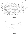
- the third wind farm side voltage source converter preferably cooperates with a second grid side voltage source converter 92 in the form of a second electrical system 90 according to another embodiment of the invention which is shown schematically in Figure 6 .
- the third wind farm side voltage source converter 94 shown in Figure 6 is identical to the third wind farm side voltage source converter described above, and likewise includes a third main controller 96 which is configured to operate in exactly the same way as the third main controller described above. As additionally illustrated in Figure 6 , the third wind farm side voltage source converter 94 has a first end 36 of a DC transmission link 38 connected to its DC terminal 40.
- the second electrical assembly 90 also includes a second grid side voltage source converter 92 which itself has a DC terminal 56 that is connected with a second end 58 of the DC transmission link 38, and also an AC terminal 60 which in use may be connected to a main AC grid 62.
- the AC terminal 60 of the second grid side voltage source converter 92 may be connected to the main AC grid 62 via a first overhead line 64 which extends from a second point of common coupling 66.
- a second transformer 68 and a second circuit breaker 70 may lie between the second point of common coupling 66 and the second grid side voltage source converter 92.
- Further remote circuit breakers 72 may lie towards either end of the first overhead line 64.
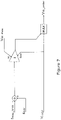
- the second grid side voltage source converter 92 includes a fourth main controller 98 which, as illustrated schematically in Figure 7 , is configured to detect an increase in the frequency at which the second grid side voltage source converter 92 is operating and thereafter increase the DC voltage at the DC terminal 56 of the second grid side voltage source converter 92 to a predetermined over-voltage value, i.e. a maximum acceptable limit V dc_max which continues to ensure the operational safety of the second grid side voltage source converter 92.
- a predetermined over-voltage value i.e. a maximum acceptable limit V dc_max which continues to ensure the operational safety of the second grid side voltage source converter 92.
- the fourth main controller 98 detects an increase in the frequency at which the second grid side voltage source converter 92 is operating by measuring the frequency f msr at the second point of common coupling 66 of the second grid side voltage source converter 92 and subtracting from this measured frequency f msr a maximum safe limit f max_limit of the frequency at the said second point of common coupling 66.
- the fourth main controller 98 changes the demanded DC voltage V LRSP of the second grid side voltage source converter 92 (i.e. as received from a higher level controller) to a DC voltage level V dc_order at which the second grid side voltage source converter 92 is intended to operate that is equal to the predetermined over-voltage value, i.e. V dc_max in order to maintain the frequency of the second grid side voltage source converter 92 at the said maximum safe frequency f max_limit .
- Such an increase in the voltage level at the DC terminal 40 of the third wind farm side voltage source converter 94 is detected by the third main controller 96 of the third wind farm side voltage source converter 94, such that it is then able automatically to reduce the active power it transfers to the second grid side voltage source converter 92 through the associated DC transmission link 38.
- the frequency at the AC terminal 60 of the second grid side voltage source converter 92 will start to increase due to the separation of the third wind farm side voltage source converter 94 and its associated wind farm, together with the second grid side voltage source converter 92, from the main AC grid 62.
- the fourth main controller 98 of the second grid side voltage source converter 92 is able to maintain the frequency at an emergency level, i.e. at a maximum safe frequency f max_limit level, very close to the nominal operating frequency level (e.g. 52 Hz for a 50 Hz system) by increasing the DC voltage of the second grid side voltage source converter 92 to the predetermined over-voltage value, i.e. V dc_max (e.g. 1.1 pu).
- the third main controller 96 of the third wind farm side voltage source converter 94 automatically reduces the active power P demand demanded of it, and thereby reduces the active power it transfers to the second grid side voltage source converter 92, when it detects the increase in voltage at its DC terminal 40 that is occasioned by the aforementioned increase in the DC voltage of the second grid side voltage source converter 92.
- the second electrical system 90 results in a reduction, or even cessation, of the active power flowing through the DC transmission link 38 such that the operating frequency of second grid side voltage source converter 92 (which is now separated from the main AC grid 62, i.e. is now islanded from the main AC grid 62) is kept to the maximum safe limit f max_limit while at the same time the voltage level at the DC terminal 56 of the second grid side voltage source converter 92, and hence also the voltage level in the DC transmission link 38, does not exceed a maximum acceptable level, i.e. the predetermined over-voltage value V dc_max .
Description
- This invention relates to a wind farm side voltage source converter, an electrical system including such a converter, and a power transmission network having a plurality of parallel-connected wind farm side voltage source converters and/or a plurality of parallel-connected electrical systems including such a converter.
- In power transmission networks alternating current (AC) power is typically converted to direct current (DC) power for transmission via overhead lines and/or under-sea cables. This conversion removes the need to compensate for the AC capacitive load effects imposed by the transmission line or cable, and thereby reduces the cost per kilometre of the lines and/or cables. Conversion from AC to DC thus becomes cost-effective when power needs to be transmitted over a long distance. It is also cost-effective when transmitting power under the sea, even for short distances, because the capacitance of undersea cables is much higher than that of overhead lines.
- In such power transmission networks, converters are required at each interface between AC and DC systems to effect the required conversion, and one such form of converter is a voltage source converter. More particularly, when interconnecting one or more wind turbines, i.e. a wind farm, with a main AC grid the power transmission network may include a wind farm side voltage source converter which interfaces directly with the wind farm and a grid side voltage source converter that interfaces directly with the main AC grid. An overhead line or an under-sea cable, i.e. a DC transmission link, extends between the wind farm side and grid side voltage source converters.
- Each of the wind farm side and grid side voltage source converters includes a plurality of series connected sub-modules that have at least one switching element which is connected in parallel with an energy storage device in the form of, e.g. a capacitor. The or each switching element may include a semiconductor device in the form of, e.g. an Insulated Gate Bipolar Transistor (IGBT), which is connected in anti-parallel with a diode although it is possible to use other semiconductor devices.
- Switching of the or each switching element selectively directs current through the capacitor or causes current to bypass the capacitor such that each sub-module is selectively able to provide a voltage. In this manner it is possible to build up a combined voltage, via the insertion of the capacitors of multiple sub-modules (with each sub-module providing its own voltage), which is higher than the voltage available from each individual sub-module.
- The sub-modules work together in this manner to provide a stepped variable voltage source. This permits the generation of an AC voltage waveform which enables the voltage source converter to provide the aforementioned power transfer functionality between a respective AC system, e.g. a wind farm or a main AC grid, and an associated DC system, e.g. a DC transmission link.
-
US 2007/121354 describes a power converter that can be used to interface a generator that provides variable voltage at variable frequency to a supply network operating at nominally fixed voltage and nominally fixed frequency. the power converter comprises a first and second active rectifier/inverters including a plurality of semiconductor power switching devices, the first active rectifier/inverter connected to the stator of the generator, a dc link connected between the first and second active rectifier/inverters, a filter connected between the second active rectifier/inverter and the supply network, the filter including network terminals. First and second controllers are provided for the first and second active rectifier/inverters, wherein the first controller uses a dc link voltage demand signal indicative of a desired dc link voltage to control the semiconductor power switching devices of the first active rectifier/inverter to achieve the desired level of dc link voltage that corresponds to the dc link voltage demand signal. The second controller uses a power demand signal indicative of the level of power to be transferred from the dc link to the supply network through the second active rectifier/inverter, and a voltage demand signal indicative of the voltage to be achieved at the network terminals of the filter to control the semiconductor power switching devices of the second active rectifier/inverter to achieve the desired levels of power and voltage that correspond to the power and voltage demand signals. - The present invention resides in a power transmission network comprising a plurality of parallel-connected wind farm side voltage source converters as defined in claim 1.
- Modifying the active power demand of the voltage source converter by introducing an artificial inertia factor compensates for a lack of mechanical resistance in the or each wind turbine of the wind farm. This, in turn, helps to resolve instability issues in a main AC grid where the power output of the wind farm is evacuated which might otherwise be caused by operation of the voltage source converter. It also helps to smooth out variations in the frequency at which the voltage source operator operates.
- Meanwhile, modifying the active power demand of the voltage source converter in response to a measured DC voltage at the DC terminal allows a DC transmission link which is, e.g. operatively associated in use with the wind farm side voltage source converter, to act as a communication medium. This in turn allows, e.g. a grid side voltage source converter connected to the other end of the DC transmission link, to control the active power output of the wind farm side voltage source converter without the need for a separate costly and unreliable telecommunication system between the wind farm side voltage source converter and, e.g. the grid side voltage source converter.
- Preferably the main controller includes a power-frequency slope sub-controller and the main controller is configured to modify the active power demand of the voltage source converter by passing the active power demand through the power-frequency slope sub-controller and thereafter applying an artificial inertia factor to the resulting frequency.
- Such a step helps directly to prevent the resulting frequency, i.e. the frequency value output by the power-frequency slope sub-controller and the frequency at which the wind farm side voltage source converter is controlled to operate, from varying too erratically. The power-frequency slope sub-controller may be configured itself to apply the artificial inertia factor.
- Such a configuration can be readily implemented by minor alteration of the operating algorithms of the power-frequency slope sub-controller.
- The artificial inertia factor takes the form of a lagging function.
- A lagging function desirably affects the rate at which the frequency value output by the power-frequency slope sub-controller varies.
- The main controller is configured to modify the active power demand of the voltage source converter received from a higher level controller in response to a measured DC voltage at the DC terminal by comparing the measured DC voltage with an expected DC voltage based on a DC voltage demand received from a higher level controller and altering the active power demand when the measured DC voltage differs from the expected DC voltage.
- Having a main controller configured in the foregoing manner allows the main controller to vary the active power output by the wind farm side voltage source converter so that it is aligned with the active power demand of, e.g. a grid side voltage source converter which in use is connected with the wind farm side voltage source converter by a DC transmission link, such that, e.g. the grid side voltage source converter is able to act as a master converter while the wind farm side converter acts as a slave converter.
- The altered active power demand may be passed through the power-frequency slope sub-controller before an artificial inertia factor is applied to the resulting frequency.
- Such an arrangement allows for the implementation of a master-slave control relationship between the wind farm side voltage source converter and, e.g. a grid side voltage source converter, in a manner whereby the wind farm side voltage source converter remains stable and subject only to smooth variations in operating frequency.
- The main controller may be configured to modify an active power demand of the voltage source converter in response to a measured DC voltage at the DC terminal by comparing the measured DC voltage with a predetermined DC over-voltage value and reducing the active power demand when the measured DC voltage is greater than or equal to the DC over-voltage value.
- Such a main controller assists the wind farm side voltage source converter to reduce the active power it outputs, e.g. and thereafter in use transmits to a grid side voltage source converter via an associated DC transmission link, in response to a change in the DC voltage presented at the DC terminal of the wind farm side voltage source converter. Such a change in the DC voltage may be occasioned by a fault in another part of the power transmission network in which the wind farm side voltage source converter is in use located, and so the foregoing arrangement permits the wind farm side voltage source converter of the invention to react to the fault without the need for a separate telecommunications system between the wind farm side voltage source converter and the other part of the power transmission network.
- There now follows a brief description of preferred embodiments of the invention, by way of non-limiting examples, with reference being made to the accompanying drawings in which:
-
Figure 1 shows a first main controller of a wind farm side voltage source converter according to an exemplary embodiment; -
Figure 2 shows a second main controller of a wind farm side voltage source converter according to an embodiment of the invention; -
Figure 3 shows respective first electrical systems and an associated power transmission network according to embodiments of the invention; -
Figure 4 shows an AC voltage-reactive power droop sub-controller; -
Figure 5 shows a third main controller of a wind farm side voltage source converter according to an exemplary embodiment; -
Figure 6 shows a second electrical system according to an exemplary embodiment; and -
Figure 7 shows a main controller of a grid side voltage source converter which forms a part of the second electrical system shown inFigure 6 . -
Figures 2-4 are related to embodiments of the invention. The exemplary embodiments shown infigures 1 and5-7 are not covered by the scope of protection as defined by the appended claims. - A wind farm side voltage source converter according an exemplary embodiment includes a DC terminal, which in use is connected to a DC transmission link (i.e. an overhead line or an under-sea cable), an AC terminal, which in use is connected to a wind farm, and a first main controller.
- The first
main controller 10 is shown schematically inFigure 1 and is configured to modify an active power demand Pdemand of the first wind farm side voltage source converter of which the firstmain controller 10 forms a part. The active power demand Pdemand, i.e. the active power that the first wind farm side voltage source converter is required to provide, is provided by a higher level controller (not shown) such as, for example, a dispatch centre. - The first
main controller 10 is configured to modify the active power demand Pdemand by introducing an artificial inertia factor. - More particularly, the first
main controller 10 includes a power-frequency slope sub-controller 12 and is configured to pass the active power demand Pdemand through the power-frequency slope sub-controller 12 in order to transform the associated active power value into a frequency value. - Before passing the active power demand Pdemand to the power-
frequency slope sub-controller 12 the firstmain controller 10 subtracts the active power demand Pdemand from an active power value Pmsr measured at a point of common coupling between the first wind farm side voltage source converter and the wind farm to which it is in use connected. - As the active power demand Pdemand passes through the power-
frequency slope sub-controller 12 the power-frequency slope sub-controller 12 applies the artificial inertia factor, which takes the form of a lagging function. In a preferred embodiment of the invention the lagging function is defined by:
- Where
- s is the angular frequency of the associated AC system, i.e. an associated
wind farm 44; and - T is a time constant
- In other embodiments of the invention the artificial inertia factor may take a different form and/or may be defined by a different function which nevertheless similarly mimics the effect of mechanical inertia.
- The frequency value resulting from the power-
frequency slope sub-controller 12, i.e. the frequency value output by the power-frequency slope sub-controller 12 and incorporating the artificial inertia factor, is added to a frequency demand fdemand. This frequency demand fdemand, i.e. the frequency at which the first wind farm side voltage source converter is required to operate, is provided by the same higher level controller as that which provides the active power demand Pdemand. - The sum of the frequency resulting from the power-
frequency slope sub-controller 12 and the frequency demand fdemand is passed through afrequency limiter 14, which prevents the summed frequency value exceeding predefined safe operating limits of the first wind farm side voltage source converter, before being output as a frequency order forder which controls the actual frequency at which the first wind farm side voltage source converter is intended to operate. - In the foregoing manner the first
main controller 10 acts as a frequency controller with the control loop embodied therein being altered by a power demand error, i.e. the difference between the active power demand Pdemand and the measured active power Pmsr. - More particularly, the first
main controller 10 helps to ensure that the frequency at which the first wind farm side voltage source converter is controlled to operate, i.e. forder, drops when the measured active power Pmsr is lower than the active power demand Pdemand, and the operating frequency forder increases when the measured active power Pmsr is higher than the active power demand Pdemand. In use a fall in the operating frequency forder causes the power angle, i.e. the angle between the wind farm voltage vector and the first wind farm side voltage source converter voltage vector, to increase, while an increase in the operating frequency forder causes the power angle to decrease. Such a phenomenon is useful in circumstances where a plurality of first wind farm side voltage source converters are connected in parallel and it is desired to have them share the power output of an associated wind farm differently according to their own individual capabilities since a change in the power angle of one voltage source converter relative to another least also to a change in the active power flowing through one voltage source converter compared to the other, as is described hereinbelow in connection with another embodiment of the invention. - Meanwhile, in use the introduction of an artificial inertia factor helps to dampen the aforesaid changes in the frequency forder that the first wind farm side voltage source converter is controlled to operate at so as to maintain the stability of the said voltage source converter.
- A wind farm side voltage source converter according to an embodiment of the invention is similar to the first wind farm side voltage converter described above and like features share the same reference numerals. The second wind farm side voltage source converter also includes a DC terminal, which in use is connected to a DC transmission link, and an AC terminal which in use is connected to a wind farm.
- However, the second wind farm side voltage source converter includes a second
main controller 20 which, while similar in some respects to the firstmain controller 10, additionally includes some differences. - The second
main controller 20 is similarly configured to modify an active power demand Pdemand of the second wind farm side voltage source converter (which is again provided by a higher level controller) by introducing an artificial inertia factor. - However, the second
main controller 20 is configured to additionally modify the active power demand Pdemand in response to a measured DC voltage Vdc_msr at the DC terminal of the second wind farm side voltage source converter, i.e. as shown inFigure 2 . - The second
main controller 20 carries out such modification by comparing the measured DC voltage Vdc_msr with an expected DC voltage and altering the active power demand Pdemand when the measured DC voltage Vdc_msr differs from the expected DC voltage to thereby produce a modified active power demand Pdemand_mod. - The expected DC voltage is based on a DC voltage demand which is provided by the same higher level control that provides the active power demand Pdemand for the second wind farm side voltage source converter. The DC voltage demand may also be known as a Load Reference Set Point (LRSP) which is a target DC voltage that all gird side voltage source converters connected to a main grid are aimed to operate at.
- A DC voltage order Vdc_order that a gird side voltage source converter, which is the subject of the DC voltage demand VLRSP provided by the higher level controller, should be controlled to operate at can be derived at zero DC current according to the following relationship

- As a result the DC voltage order Vdc_order will equal the DC voltage demand VLRSP received from the higher level controller when the active power received by the grid side voltage source converter is at the same level as the active power demand Pdemand_grid_side instruction it has received from the higher level controler. Thus, if the actual active power received by the grid side voltage source converter is different from its active power demand Pdemand_grid_side then the actual DC voltage at which the grid side voltage source converter is operating will likewise differ from the DC voltage demand VLRSP.
- As a result the voltage level of a DC transmission link which in use connects the second wind farm side voltage source converter with a grid side voltage source converter that is the subject of the DC voltage demand VLRSP provided by the higher level controller, will also differ from the DC voltage demand VLRSP.
- The voltage level of the DC transmission link manifests itself as a measured DC voltage Vdc_msr at the second wind farm side voltage source converter, and so any difference between the voltage level of the DC transmission link and the DC voltage demand VLRSP is detectable by the second
main controller 20 of the second wind farm side voltage source converter. - In adopting the foregoing approach it is necessary to account for a voltage drop ΔV along the DC transmission link, and so the expected DC voltage is given by the sum of the DC voltage demand VLRSP and the said voltage drop ΔV along the DC transmission link which may be given by

- Idc is the level of DC current flowing through the DC transmission link; and
- Rcable is the resistance of the DC transmission link.
- Accordingly, in order to produce a modified active power demand Pdemand_mod the second
main controller 20 sums the DC voltage demand VLRSP and the voltage drop ΔV along the DC transmission link and then subtracts this from the measured DC voltage Vdc_msr at the DC terminal of the second wind farm side voltage source converter. - The output of this manipulation is then preferably amplified by multiplying it by a
gain factor 22 before being summed with the active power demand Pdemand received from the higher level controller to give the desired modified active power demand Pdemand_mod value. - Thereafter operation of the second
main controller 20 and the manner in which it introduces an artificial inertia factor is similar to the manner in which the firstmain controller 10 achieves such a step. - The second main controller subtracts the modified active power demand Pdemand_mod from an active power value Pmsr measured at the point of common coupling between the second wind farm side voltage source converter and the wind farm to which it is in use connected, and then applies an artificial inertia factor in the form of a lagging function as the altered modified active power demand Pdemand_mod passes through a power-
frequency slope sub-controller 12. The frequency value resulting from the power-frequency slope sub-controller 12 is again then added to a frequency demand fdemand provided by the higher level controller, and the sum of the frequency resulting from the power-frequency slope sub-controller 12 and the frequency demand fdemand is passed through afrequency limiter 14 before being output as a frequency order forder which controls the frequency at which the second wind farm side voltage source converter is intended to operate. - In use the second
main controller 20 is therefore able to detect changes in the voltage level of a DC transmission link to which it is connected and thereafter automatically modify the active power demand Pdemand it receives from a higher level controller so that it can become aligned with, e.g. the active power Pdemand_grid_side demanded of a grid side voltage source converter connected to the other end of the DC transmission link. - The second wind farm side voltage source converter desirably forms a part of a first
electrical system 30 within which it is identified byreference numeral 32. The firstelectrical system 30 may itself form a part of apower transmission network 34 that includes a plurality of the firstelectrical systems 30 connected in parallel with one another, as shown inFigure 3 . Each of the firstelectrical systems 30 and thepower transmission network 34 is an embodiment of the invention. - Each first
electrical system 30 includes a said second wind farm sidevoltage source converter 32 which has afirst end 36 of aDC transmission link 38 connected to theDC terminal 40 thereof. Each second wind farm sidevoltage source converter 32 also includes anAC terminal 42 which is, in use, connected to acorresponding wind farm 44 that includes at least onewind turbine 46. The second wind farm sidevoltage source converter 32 may be connected to thewind farm 44 via a first point ofcommon coupling 48 and afirst transformer 50. Afirst circuit breaker 52 may also lie between the first point ofcommon coupling 48 and thefirst transformer 50, although this need not necessarily be the case. - Each first
electrical system 30 also includes a first grid sidevoltage source converter 54 which has a further DC terminal to which a second end 58 of theDC transmission link 38 is connected. The first grid sidevoltage source converter 54 also includes anAC terminal 60 which, in use, is connected to amain AC grid 62. - More particularly, in the example shown, the first grid side
voltage source converter 54 in one of the firstelectrical systems 30 may be connected with themain AC grid 62 via a firstoverhead line 64 which extends from a second point ofcommon coupling 66. In such an arrangement asecond transformer 68 and asecond circuit breaker 70 may lie between the second point ofcommon coupling 66 and the first grid sidevoltage source converter 54. Furtherremote circuit breakers 72 may lie towards either end of thefirst transmission line 64. - A pair (or more) of first
electrical systems 30 may also be connected with the main AC grid via a single, shared secondoverhead line 74 which similarly extends from a second point ofcommon coupling 66. Preferably asecond transformer 68 and asecond circuit breaker 70 lie between the second point ofcommon coupling 66 and the first grid sidevoltage source converter 54 of each of the pair of firstelectrical systems 30. Further remote circuit breakers similarly may lie towards either end of the secondoverhead line 74. - In other embodiments of the invention (not shown) the or each
overhead line - As described hereinabove, each second wind farm side
voltage source converter 32 includes a secondmain controller 20 which is configured to compare the measured DC voltage Vdc_msr at theDC terminal 40 of the corresponding second wind farm sidevoltage source converter 32 with an expected DC voltage that is defined by the sum of a DC voltage demand VLRSP of the first grid side voltage source converter 54 (i.e. as received from a higher level controller) and the voltage drop ΔV along theDC transmission link 38. Each secondmain controller 20 is still further configured to alter the active power demand Pdemand of the corresponding second wind farm side voltage source converter 32 (i.e. as received from the higher level controller) when the measured DC voltage Vdc_msr differs from the expected DC voltage. - In this way the second wind farm side
voltage source converter 32 within each firstelectrical system 30 automatically modifies the active power demand Pdemand it receives from the higher level controller so that the active power it transfers is aligned with the active power Pdemand_grid_side demanded by the first grid sidevoltage source converter 54 to which it is connected by the correspondingDC transmission link 38. - It follows that in each first
electrical system 30 the first grid sidevoltage source converter 54 controls the flow of active power through theDC transmission link 38, rather than the corresponding second wind farm sidevoltage source converter 32 affecting such control. As a result each first grid sidevoltage source converter 54 is considered to be a master converter, while each second wind farm sidevoltage source converter 32 acts as a slave converter. -
Adjacent wind farms 44 in thepower transmission network 34 described above are connected to one another by a respective AC link 76 which may be an under-sea cable or an overhead line. - If the impedance of each AC link 76 is sufficiently high then each second wind farm side
voltage source converter 32 is able independently to control the AC voltage at which it operates. - However, if the impedance of each AC link 76 is very small then each second
main controller 20 may additionally include an AC voltage-reactivepower droop sub-controller 78, as shown inFigure 4 , so that the AC voltage at which each second wind farm sidevoltage source converter 32 operates can be controlled jointly by the various secondmain controllers 20. - As illustrated schematically in
Figure 4 , each AC voltage-reactivepower droop sub-controller 78 subtracts an AC reactive power demand Qdemand (which it receives from a higher level controller) from a measured AC reactive power Qmsr (which is taken at the corresponding first point of common coupling 48) and passes the result through a reactive power-voltage slope sub-controller 80 that converts the result into a voltage. The resulting voltage is in turn subtracted from a demanded AC voltage magnitude VAC_demand provided by the higher level controller, before being passed through avoltage limiter 82 which prevents the further resulting voltage value from exceeding predefined safe operating limits of the second wind farm sidevoltage source converter 32. The output voltage value VAC_order from the voltage-reactivepower droop sub-controller 78 is the AC voltage level at which the corresponding second wind farm sidevoltage source converter 32 is controlled to operate at. - A wind farm side voltage source converter according to another exemplary embodiment is similar to each of the first and second wind farm side voltage source converters described hereinabove.
- In this regard the third wind farm side voltage source converter includes a third
main controller 110 which introduces an artificial inertia factor in a similar manner to the secondmain controller 20, i.e. by subtracting a modified active power demand Pdemand_mod from an active power value Pmsr measured at the point of common coupling between the third wind farm side voltage source converter and the wind farm to which it is in use connected, and then by applying an artificial inertia factor in the form of a lagging function as the altered active power demand Pdemand_mod passes through a power-frequency slope sub-controller 12. The frequency value resulting from the power-frequency slope sub-controller is again then added to a frequency demand fdemand provided by a higher level controller, and the sum of the frequency resulting from the power-frequency slope sub-controller 12 and the frequency demand fdemand is passed through afrequency limiter 14 before being output as a frequency order forder which controls the frequency at which the third wind farm side voltage source converter is intended to operate. - However the third main controller produces the modified active power demand Pdemand_mod in a different way to the second
main controller 20, as is illustrated schematically inFigure 5 . - More particularly, the third main controller is configured to compare a measured DC voltage Vdc_msr, i.e. as measured at the DC terminal of the third wind farm side voltage source converter, with a predetermined DC over-voltage value which, in the embodiment shown, equates to a maximum acceptable limit Vdc_max in terms of the operational safety of a grid side voltage source converter to which the third wind farm side voltage source converter is, in use, connected.
- In the embodiment shown, when the measured DC voltage Vdc_msr equals the predetermined DC over-voltage value Vdc_max the third
main controller 110 reduces the active power demand Pdemand received from the higher level controller to a lower modified active power demand Pdemand_mod (which it then subtracts from the active power value measured at the first point of common coupling between the third wind farm side voltage source converter and the wind farm to which it is in use connected, before applying the artificial inertia factor). In other embodiments, however, the thirdmain controller 110 may reduce the active power demand Pdemand received from the higher level controller to a lower modified active power demand Pdemand_mod when the measured DC voltage Vdc_msr exceeds the predetermined DC over-voltage value Vdc_max. - In use the third wind farm side voltage source converter is therefore, via operation of the third main controller therein, able to reduce the active power it transfers, e.g. to a grid side voltage source converter to which it is connected in use via an associated DC transmission link, in response to a change in the DC voltage presented at its DC terminal, e.g. as may be occasioned by a fault in another part of the power transmission network in which the third wind farm side voltage source converter is in use located.
- In this regard the third wind farm side voltage source converter preferably cooperates with a second grid side
voltage source converter 92 in the form of a secondelectrical system 90 according to another embodiment of the invention which is shown schematically inFigure 6 . - The third wind farm side
voltage source converter 94 shown inFigure 6 is identical to the third wind farm side voltage source converter described above, and likewise includes a thirdmain controller 96 which is configured to operate in exactly the same way as the third main controller described above. As additionally illustrated inFigure 6 , the third wind farm sidevoltage source converter 94 has afirst end 36 of aDC transmission link 38 connected to itsDC terminal 40. - As mentioned above, the second
electrical assembly 90 also includes a second grid sidevoltage source converter 92 which itself has aDC terminal 56 that is connected with a second end 58 of theDC transmission link 38, and also anAC terminal 60 which in use may be connected to amain AC grid 62. TheAC terminal 60 of the second grid sidevoltage source converter 92 may be connected to themain AC grid 62 via a firstoverhead line 64 which extends from a second point ofcommon coupling 66. In such an arrangement asecond transformer 68 and asecond circuit breaker 70 may lie between the second point ofcommon coupling 66 and the second grid sidevoltage source converter 92. Furtherremote circuit breakers 72 may lie towards either end of the firstoverhead line 64. - The second grid side
voltage source converter 92 includes a fourthmain controller 98 which, as illustrated schematically inFigure 7 , is configured to detect an increase in the frequency at which the second grid sidevoltage source converter 92 is operating and thereafter increase the DC voltage at theDC terminal 56 of the second grid sidevoltage source converter 92 to a predetermined over-voltage value, i.e. a maximum acceptable limit Vdc_max which continues to ensure the operational safety of the second grid sidevoltage source converter 92. - More particularly the fourth
main controller 98 detects an increase in the frequency at which the second grid sidevoltage source converter 92 is operating by measuring the frequency fmsr at the second point ofcommon coupling 66 of the second grid sidevoltage source converter 92 and subtracting from this measured frequency fmsr a maximum safe limit fmax_limit of the frequency at the said second point ofcommon coupling 66. - Thereafter, if the measured frequency fmsr is greater than the maximum safe frequency fmax_limit the fourth
main controller 98 changes the demanded DC voltage VLRSP of the second grid side voltage source converter 92 (i.e. as received from a higher level controller) to a DC voltage level Vdc_order at which the second grid sidevoltage source converter 92 is intended to operate that is equal to the predetermined over-voltage value, i.e. Vdc_max in order to maintain the frequency of the second grid sidevoltage source converter 92 at the said maximum safe frequency fmax_limit. This in turn results in the voltage level at theDC terminal 56 of the second grid sidevoltage source converter 92, and hence (via the DC transmission link 38) the voltage level at theDC terminal 40 of the third wind farm sidevoltage source converter 94, increasing to the predetermined over-voltage value, i.e. Vdc_max. - Such an increase in the voltage level at the
DC terminal 40 of the third wind farm sidevoltage source converter 94 is detected by the thirdmain controller 96 of the third wind farm sidevoltage source converter 94, such that it is then able automatically to reduce the active power it transfers to the second grid sidevoltage source converter 92 through the associatedDC transmission link 38. - For example, if the
remote circuit breaker 72 closest to themain AC grid 62 trips due to an AC fault in themain AC grid 62, then the frequency at theAC terminal 60 of the second grid sidevoltage source converter 92 will start to increase due to the separation of the third wind farm sidevoltage source converter 94 and its associated wind farm, together with the second grid sidevoltage source converter 92, from themain AC grid 62. - However, the fourth
main controller 98 of the second grid sidevoltage source converter 92 is able to maintain the frequency at an emergency level, i.e. at a maximum safe frequency fmax_limit level, very close to the nominal operating frequency level (e.g. 52 Hz for a 50 Hz system) by increasing the DC voltage of the second grid sidevoltage source converter 92 to the predetermined over-voltage value, i.e. Vdc_max (e.g. 1.1 pu). - At the same time the third
main controller 96 of the third wind farm sidevoltage source converter 94 automatically reduces the active power Pdemand demanded of it, and thereby reduces the active power it transfers to the second grid sidevoltage source converter 92, when it detects the increase in voltage at itsDC terminal 40 that is occasioned by the aforementioned increase in the DC voltage of the second grid sidevoltage source converter 92. - As a result the second
electrical system 90, and the cooperation of the third wind farm sidevoltage source converter 94 and second grid sidevoltage source converter 92 included therein, results in a reduction, or even cessation, of the active power flowing through theDC transmission link 38 such that the operating frequency of second grid side voltage source converter 92 (which is now separated from themain AC grid 62, i.e. is now islanded from the main AC grid 62) is kept to the maximum safe limit fmax_limit while at the same time the voltage level at theDC terminal 56 of the second grid sidevoltage source converter 92, and hence also the voltage level in theDC transmission link 38, does not exceed a maximum acceptable level, i.e. the predetermined over-voltage value Vdc_max.
Claims (3)
- A power transmission network (34) comprising a plurality of parallel-connected wind farm side voltage source converters (32), each wind farm side voltage source converter (32) comprising:a DC terminal (40) for connection to a DC transmission link (38),an AC terminal (42) for connection to a wind farm (44) including at least one wind turbine (46), wherein adjacent wind farms (44) in the power transmission network (34) are connected to one another by a respective AC link (76), anda main controller (20) configured to modify an active power demand (Pdemand) of the wind farm side voltage source converter (32) received from a higher level controller in response to a measured DC voltage (Vdc_msr) at the DC terminal (40) and an artificial inertia factor, wherein the main controller (20) includes a power-frequency slope sub-controller (12) configured to transform an active power value into a frequency value, and the main controller (20) is configured to modify the active power demand (Pdemand) of the wind farm side voltage source converter by passing the active power demand (Pdemand) through the power-frequency slope sub-controller (12) and thereafter applying an artificial inertia factor to the resulting frequency, wherein the artificial inertia factor takes the form of a lagging function configured to desirably affect the rate at which the frequency value output by the power-frequency slope sub-controller (12) varies;the power transmission network (34) further comprising:a first end (36) of a DC transmission link (38) connected to said DC terminal (40);a grid side voltage source converter (54) including a DC terminal connected to a second end (58) of each DC transmission link (38), each grid side voltage source converter (54) comprising an AC terminal (60) for connection to a main AC grid (62); withthe main controller (20) of each wind farm side voltage source converter (32) being configured to:compare the measured DC voltage (Vdc_msr) at the DC terminal (40) of the wind farm side voltage source converter (32) with an expected DC voltage defined by the sum of a DC voltage demand (VLRSP) of the grid side voltage source converter (54) received from a higher level controller and the voltage drop (ΔV) along the DC transmission link (38); andalter the active power demand (Pdemand) of the wind farm side voltage source converter (32) received from the higher level controller when the measured DC voltage (Vdc_msr) differs from the expected DC voltage, wherein, if an impedance of each AC link (76) is sufficiently high, then each wind farm side voltage source converter (32) is configured to independently control the AC voltage at which it operates, otherwise, each main controller (20) additionally includes an AC voltage-reactive power droop sub-controller (78), so that the AC voltage at which each wind farm side voltage source converter (32) operates can be controlled jointly by the various main controllers (20).
- The power transmission network (34) according to Claim 1, wherein each power-frequency slope sub-controller (12) is configured itself to apply the artificial inertia factor.
- The power transmission network (34) according to any of claims 1 and 2, wherein
the altered active power demand (Pdemand_mod) is passed through each power-frequency slope sub-controller (12) before an artificial inertia factor is applied to the resulting frequency.
Priority Applications (4)
| Application Number | Priority Date | Filing Date | Title |
|---|---|---|---|
| EP14275095.9A EP2940824B1 (en) | 2014-04-29 | 2014-04-29 | Improvements in or relating to voltage source converters |
| CN201580023520.7A CN106537759B (en) | 2014-04-29 | 2015-04-28 | Improvements in or relating to voltage source converters |
| PCT/EP2015/059146 WO2015165876A1 (en) | 2014-04-29 | 2015-04-28 | Improvements in or relating to voltage source converters |
| US15/307,566 US10305291B2 (en) | 2014-04-29 | 2015-04-28 | Voltage source convertors |
Applications Claiming Priority (1)
| Application Number | Priority Date | Filing Date | Title |
|---|---|---|---|
| EP14275095.9A EP2940824B1 (en) | 2014-04-29 | 2014-04-29 | Improvements in or relating to voltage source converters |
Publications (2)
| Publication Number | Publication Date |
|---|---|
| EP2940824A1 EP2940824A1 (en) | 2015-11-04 |
| EP2940824B1 true EP2940824B1 (en) | 2022-11-23 |
Family
ID=50588605
Family Applications (1)
| Application Number | Title | Priority Date | Filing Date |
|---|---|---|---|
| EP14275095.9A Active EP2940824B1 (en) | 2014-04-29 | 2014-04-29 | Improvements in or relating to voltage source converters |
Country Status (4)
| Country | Link |
|---|---|
| US (1) | US10305291B2 (en) |
| EP (1) | EP2940824B1 (en) |
| CN (1) | CN106537759B (en) |
| WO (1) | WO2015165876A1 (en) |
Families Citing this family (13)
| Publication number | Priority date | Publication date | Assignee | Title |
|---|---|---|---|---|
| US9859710B2 (en) * | 2012-10-08 | 2018-01-02 | Vestas Wind Systems A/S | Line impedance compensation system |
| EP3070805B1 (en) * | 2015-03-19 | 2021-04-28 | General Electric Technology GmbH | Power transmission network |
| EP3070807B1 (en) * | 2015-03-19 | 2020-09-09 | General Electric Technology GmbH | Power transmission network |
| CN105226719B (en) * | 2015-11-09 | 2017-11-07 | 安徽工程大学 | The energy storage control system and its control method regulated and controled for wind power |
| US10746043B2 (en) * | 2018-03-22 | 2020-08-18 | Mitsubishi Heavy Industries, Ltd. | Power source, adjusting power instructing apparatus, method, and recording medium for changing adjusting power |
| DE102018125529A1 (en) * | 2018-10-15 | 2020-04-16 | Wobben Properties Gmbh | Dynamic wind power plant |
| KR102577911B1 (en) * | 2018-11-16 | 2023-09-14 | 상라오 징코 솔라 테크놀러지 디벨롭먼트 컴퍼니, 리미티드 | Power converting apparatus, photovoltaic module, and photovoltaic system including the same |
| CN109787295B (en) * | 2019-02-26 | 2022-03-18 | 东北电力大学 | Wind power ultra-short term prediction calculation method considering wind power plant state |
| EP3843231A1 (en) | 2019-12-23 | 2021-06-30 | General Electric Technology GmbH | Hvdc power transmission |
| CN112983753B (en) * | 2021-03-03 | 2022-06-28 | 南京理工大学 | Draught fan mechanical dynamic simulation method and system based on speed-sensorless ground test bed |
| WO2023122601A1 (en) | 2021-12-20 | 2023-06-29 | Flower Turbines, Inc. | A shaftless generator for a fluid turbine |
| US11891980B2 (en) | 2022-02-08 | 2024-02-06 | Flower Turbines, Inc. | Coordinating blade orientation to optimize cluster power output |
| US20230324866A1 (en) | 2022-04-12 | 2023-10-12 | Mark Daniel Farb | Dual mode turbine collects energy during low wind conditions |
Citations (1)
| Publication number | Priority date | Publication date | Assignee | Title |
|---|---|---|---|---|
| US20060208574A1 (en) * | 2005-03-18 | 2006-09-21 | Wisconsin Alumni Research Foundation | Control of small distributed energy resources |
Family Cites Families (11)
| Publication number | Priority date | Publication date | Assignee | Title |
|---|---|---|---|---|
| IT8682564A0 (en) | 1986-07-30 | 1986-07-30 | Nordica Spa | CONTAINER FOR ELECTRICAL AND ELECTRO-PNEUMATIC EQUIPMENT. |
| JPH09163605A (en) | 1995-11-29 | 1997-06-20 | Toyo Electric Mfg Co Ltd | Integrated compensation device for electric power system |
| US7511385B2 (en) * | 2005-11-11 | 2009-03-31 | Converteam Ltd | Power converters |
| WO2010049412A1 (en) * | 2008-10-27 | 2010-05-06 | Vestas Wind Systems A/S | Direct power and stator flux vector control of a generator for wind energy conversion system |
| US8068352B2 (en) * | 2008-12-19 | 2011-11-29 | Caterpillar Inc. | Power inverter control for grid-tie transition |
| WO2011039794A1 (en) | 2009-09-29 | 2011-04-07 | 三菱電機株式会社 | Power converter |
| US9093924B2 (en) * | 2010-08-18 | 2015-07-28 | Vestas Wind Systems A/S | Method of controlling a grid side converter of a wind turbine and system suitable therefore |
| CN101997312A (en) * | 2010-12-08 | 2011-03-30 | 浙江省电力试验研究院 | Method for quickly and effectively inhibiting frequency fluctuation of island power grid |
| DK2528184T3 (en) * | 2011-05-25 | 2014-10-20 | Siemens Ag | Method and device for controlling a DC transmission connection |
| CN102904272B (en) | 2011-07-29 | 2015-07-29 | 通用电气公司 | There is energy conversion system and the method for the transient affair ride-through capability of improvement |
| EP2597746B1 (en) | 2011-11-23 | 2020-11-18 | Siemens Aktiengesellschaft | Method of controlling the power input to a HVDC transmission link |
-
2014
- 2014-04-29 EP EP14275095.9A patent/EP2940824B1/en active Active
-
2015
- 2015-04-28 WO PCT/EP2015/059146 patent/WO2015165876A1/en active Application Filing
- 2015-04-28 US US15/307,566 patent/US10305291B2/en active Active
- 2015-04-28 CN CN201580023520.7A patent/CN106537759B/en active Active
Patent Citations (1)
| Publication number | Priority date | Publication date | Assignee | Title |
|---|---|---|---|---|
| US20060208574A1 (en) * | 2005-03-18 | 2006-09-21 | Wisconsin Alumni Research Foundation | Control of small distributed energy resources |
Also Published As
| Publication number | Publication date |
|---|---|
| US10305291B2 (en) | 2019-05-28 |
| EP2940824A1 (en) | 2015-11-04 |
| WO2015165876A1 (en) | 2015-11-05 |
| US20170054301A1 (en) | 2017-02-23 |
| CN106537759B (en) | 2019-12-24 |
| CN106537759A (en) | 2017-03-22 |
Similar Documents
| Publication | Publication Date | Title |
|---|---|---|
| EP2940824B1 (en) | Improvements in or relating to voltage source converters | |
| US10411616B2 (en) | Controlling a power transmission network | |
| EP2589127B1 (en) | A multi-terminal dc transmission system and method and means for control thereof | |
| US10250042B2 (en) | Wind-turbine converter control for modular string converters | |
| EP2673870B1 (en) | Control arrangement and method for regulating the output voltage of a dc source power converter connected to a multi-source dc system | |
| CN102959822A (en) | Method for controlling power flow within DC power transmission network and control device | |
| US9853582B2 (en) | Converter interconnected with a wind power generation farm to enable continuous power transmission and operating method thereof | |
| US20150260161A1 (en) | Control device for voltage source converter and operating method thereof | |
| US9825523B2 (en) | Control arrangement and method for regulating the output current of a dc source power converter connected to a multi-source dc system | |
| CN108701995B (en) | Power conversion circuit, power system and method thereof | |
| KR101630511B1 (en) | Converter controller and operating method thereof | |
| US10530160B2 (en) | Power transmission network | |
| Brenna et al. | Real time simulation of smart grids for interface protection test and analysis | |
| JP2016101030A (en) | Power transmission system and control method therefor | |
| JP6791749B2 (en) | DC power transmission system and its control device | |
| EP3843231A1 (en) | Hvdc power transmission | |
| IT201800003474A1 (en) | Improved storage system. |
Legal Events
| Date | Code | Title | Description |
|---|---|---|---|
| PUAI | Public reference made under article 153(3) epc to a published international application that has entered the european phase |
Free format text: ORIGINAL CODE: 0009012 |
|
| AK | Designated contracting states |
Kind code of ref document: A1 Designated state(s): AL AT BE BG CH CY CZ DE DK EE ES FI FR GB GR HR HU IE IS IT LI LT LU LV MC MK MT NL NO PL PT RO RS SE SI SK SM TR |
|
| AX | Request for extension of the european patent |
Extension state: BA ME |
|
| 17P | Request for examination filed |
Effective date: 20160503 |
|
| RBV | Designated contracting states (corrected) |
Designated state(s): AL AT BE BG CH CY CZ DE DK EE ES FI FR GB GR HR HU IE IS IT LI LT LU LV MC MK MT NL NO PL PT RO RS SE SI SK SM TR |
|
| RAP1 | Party data changed (applicant data changed or rights of an application transferred) |
Owner name: GENERAL ELECTRIC TECHNOLOGY GMBH |
|
| STAA | Information on the status of an ep patent application or granted ep patent |
Free format text: STATUS: EXAMINATION IS IN PROGRESS |
|
| 17Q | First examination report despatched |
Effective date: 20170508 |
|
| STAA | Information on the status of an ep patent application or granted ep patent |
Free format text: STATUS: EXAMINATION IS IN PROGRESS |
|
| STAA | Information on the status of an ep patent application or granted ep patent |
Free format text: STATUS: EXAMINATION IS IN PROGRESS |
|
| GRAP | Despatch of communication of intention to grant a patent |
Free format text: ORIGINAL CODE: EPIDOSNIGR1 |
|
| STAA | Information on the status of an ep patent application or granted ep patent |
Free format text: STATUS: GRANT OF PATENT IS INTENDED |
|
| INTG | Intention to grant announced |
Effective date: 20220228 |
|
| GRAS | Grant fee paid |
Free format text: ORIGINAL CODE: EPIDOSNIGR3 |
|
| GRAA | (expected) grant |
Free format text: ORIGINAL CODE: 0009210 |
|
| STAA | Information on the status of an ep patent application or granted ep patent |
Free format text: STATUS: THE PATENT HAS BEEN GRANTED |
|
| AK | Designated contracting states |
Kind code of ref document: B1 Designated state(s): AL AT BE BG CH CY CZ DE DK EE ES FI FR GB GR HR HU IE IS IT LI LT LU LV MC MK MT NL NO PL PT RO RS SE SI SK SM TR |
|
| REG | Reference to a national code |
Ref country code: GB Ref legal event code: FG4D |
|
| REG | Reference to a national code |
Ref country code: CH Ref legal event code: EP |
|
| REG | Reference to a national code |
Ref country code: DE Ref legal event code: R096 Ref document number: 602014084630 Country of ref document: DE |
|
| REG | Reference to a national code |
Ref country code: IE Ref legal event code: FG4D |
|
| REG | Reference to a national code |
Ref country code: AT Ref legal event code: REF Ref document number: 1512800 Country of ref document: AT Kind code of ref document: T Effective date: 20220915 |
|
| PUAC | Information related to the publication of a b1 document modified or deleted |
Free format text: ORIGINAL CODE: 0009299EPPU |
|
| STAA | Information on the status of an ep patent application or granted ep patent |
Free format text: STATUS: GRANT OF PATENT IS INTENDED |
|
| REG | Reference to a national code |
Ref country code: CH Ref legal event code: PK Free format text: DIE ERTEILUNG WURDE VOM EPA WIDERRUFEN. |
|
| DB1 | Publication of patent cancelled |
Effective date: 20220916 |
|
| GRAA | (expected) grant |
Free format text: ORIGINAL CODE: 0009210 |
|
| STAA | Information on the status of an ep patent application or granted ep patent |
Free format text: STATUS: THE PATENT HAS BEEN GRANTED |
|
| REG | Reference to a national code |
Ref country code: DE Ref legal event code: R107 Ref document number: 602014084630 Country of ref document: DE |
|
| REG | Reference to a national code |
Ref country code: AT Ref legal event code: REZ Ref document number: 1512800 Country of ref document: AT Kind code of ref document: T Effective date: 20220817 |
|
| AK | Designated contracting states |
Kind code of ref document: B1 Designated state(s): AL AT BE BG CH CY CZ DE DK EE ES FI FR GB GR HR HU IE IS IT LI LT LU LV MC MK MT NL NO PL PT RO RS SE SI SK SM TR |
|
| REG | Reference to a national code |
Ref country code: CH Ref legal event code: EP |
|
| REG | Reference to a national code |
Ref country code: AT Ref legal event code: REF Ref document number: 1512800 Country of ref document: AT Kind code of ref document: T Effective date: 20221215 Ref country code: DE Ref legal event code: R096 Ref document number: 602014084630 Country of ref document: DE |
|
| REG | Reference to a national code |
Ref country code: SE Ref legal event code: TRGR |
|
| PG25 | Lapsed in a contracting state [announced via postgrant information from national office to epo] |
Ref country code: RS Free format text: LAPSE BECAUSE OF FAILURE TO SUBMIT A TRANSLATION OF THE DESCRIPTION OR TO PAY THE FEE WITHIN THE PRESCRIBED TIME-LIMIT Effective date: 20221123 |
|
| PG25 | Lapsed in a contracting state [announced via postgrant information from national office to epo] |
Ref country code: IS Free format text: LAPSE BECAUSE OF FAILURE TO SUBMIT A TRANSLATION OF THE DESCRIPTION OR TO PAY THE FEE WITHIN THE PRESCRIBED TIME-LIMIT Effective date: 20221217 |
|
| REG | Reference to a national code |
Ref country code: LT Ref legal event code: MG9D |
|
| REG | Reference to a national code |
Ref country code: NL Ref legal event code: MP Effective date: 20221123 |
|
| REG | Reference to a national code |
Ref country code: AT Ref legal event code: MK05 Ref document number: 1512800 Country of ref document: AT Kind code of ref document: T Effective date: 20221123 |
|
| PG25 | Lapsed in a contracting state [announced via postgrant information from national office to epo] |
Ref country code: PT Free format text: LAPSE BECAUSE OF FAILURE TO SUBMIT A TRANSLATION OF THE DESCRIPTION OR TO PAY THE FEE WITHIN THE PRESCRIBED TIME-LIMIT Effective date: 20230323 Ref country code: NO Free format text: LAPSE BECAUSE OF FAILURE TO SUBMIT A TRANSLATION OF THE DESCRIPTION OR TO PAY THE FEE WITHIN THE PRESCRIBED TIME-LIMIT Effective date: 20230223 Ref country code: LT Free format text: LAPSE BECAUSE OF FAILURE TO SUBMIT A TRANSLATION OF THE DESCRIPTION OR TO PAY THE FEE WITHIN THE PRESCRIBED TIME-LIMIT Effective date: 20221123 Ref country code: FI Free format text: LAPSE BECAUSE OF FAILURE TO SUBMIT A TRANSLATION OF THE DESCRIPTION OR TO PAY THE FEE WITHIN THE PRESCRIBED TIME-LIMIT Effective date: 20221123 Ref country code: ES Free format text: LAPSE BECAUSE OF FAILURE TO SUBMIT A TRANSLATION OF THE DESCRIPTION OR TO PAY THE FEE WITHIN THE PRESCRIBED TIME-LIMIT Effective date: 20221123 Ref country code: AT Free format text: LAPSE BECAUSE OF FAILURE TO SUBMIT A TRANSLATION OF THE DESCRIPTION OR TO PAY THE FEE WITHIN THE PRESCRIBED TIME-LIMIT Effective date: 20221123 |
|
| PGFP | Annual fee paid to national office [announced via postgrant information from national office to epo] |
Ref country code: FR Payment date: 20230321 Year of fee payment: 10 |
|
| PG25 | Lapsed in a contracting state [announced via postgrant information from national office to epo] |
Ref country code: LV Free format text: LAPSE BECAUSE OF FAILURE TO SUBMIT A TRANSLATION OF THE DESCRIPTION OR TO PAY THE FEE WITHIN THE PRESCRIBED TIME-LIMIT Effective date: 20221123 Ref country code: HR Free format text: LAPSE BECAUSE OF FAILURE TO SUBMIT A TRANSLATION OF THE DESCRIPTION OR TO PAY THE FEE WITHIN THE PRESCRIBED TIME-LIMIT Effective date: 20221123 |
|
| PGFP | Annual fee paid to national office [announced via postgrant information from national office to epo] |
Ref country code: SE Payment date: 20230327 Year of fee payment: 10 Ref country code: GB Payment date: 20230321 Year of fee payment: 10 |
|
| P01 | Opt-out of the competence of the unified patent court (upc) registered |
Effective date: 20230522 |
|
| PG25 | Lapsed in a contracting state [announced via postgrant information from national office to epo] |
Ref country code: NL Free format text: LAPSE BECAUSE OF FAILURE TO SUBMIT A TRANSLATION OF THE DESCRIPTION OR TO PAY THE FEE WITHIN THE PRESCRIBED TIME-LIMIT Effective date: 20221123 Ref country code: AL Free format text: LAPSE BECAUSE OF FAILURE TO SUBMIT A TRANSLATION OF THE DESCRIPTION OR TO PAY THE FEE WITHIN THE PRESCRIBED TIME-LIMIT Effective date: 20221123 |
|
| PG25 | Lapsed in a contracting state [announced via postgrant information from national office to epo] |
Ref country code: SM Free format text: LAPSE BECAUSE OF FAILURE TO SUBMIT A TRANSLATION OF THE DESCRIPTION OR TO PAY THE FEE WITHIN THE PRESCRIBED TIME-LIMIT Effective date: 20221123 Ref country code: RO Free format text: LAPSE BECAUSE OF FAILURE TO SUBMIT A TRANSLATION OF THE DESCRIPTION OR TO PAY THE FEE WITHIN THE PRESCRIBED TIME-LIMIT Effective date: 20221123 Ref country code: EE Free format text: LAPSE BECAUSE OF FAILURE TO SUBMIT A TRANSLATION OF THE DESCRIPTION OR TO PAY THE FEE WITHIN THE PRESCRIBED TIME-LIMIT Effective date: 20221123 Ref country code: DK Free format text: LAPSE BECAUSE OF FAILURE TO SUBMIT A TRANSLATION OF THE DESCRIPTION OR TO PAY THE FEE WITHIN THE PRESCRIBED TIME-LIMIT Effective date: 20221123 Ref country code: CZ Free format text: LAPSE BECAUSE OF FAILURE TO SUBMIT A TRANSLATION OF THE DESCRIPTION OR TO PAY THE FEE WITHIN THE PRESCRIBED TIME-LIMIT Effective date: 20221123 |
|
| PGFP | Annual fee paid to national office [announced via postgrant information from national office to epo] |
Ref country code: DE Payment date: 20230321 Year of fee payment: 10 |
|
| REG | Reference to a national code |
Ref country code: DE Ref legal event code: R097 Ref document number: 602014084630 Country of ref document: DE |
|
| PG25 | Lapsed in a contracting state [announced via postgrant information from national office to epo] |
Ref country code: SK Free format text: LAPSE BECAUSE OF FAILURE TO SUBMIT A TRANSLATION OF THE DESCRIPTION OR TO PAY THE FEE WITHIN THE PRESCRIBED TIME-LIMIT Effective date: 20221123 |
|
| PLBE | No opposition filed within time limit |
Free format text: ORIGINAL CODE: 0009261 |
|
| STAA | Information on the status of an ep patent application or granted ep patent |
Free format text: STATUS: NO OPPOSITION FILED WITHIN TIME LIMIT |
|
| 26N | No opposition filed |
Effective date: 20230824 |
|
| PG25 | Lapsed in a contracting state [announced via postgrant information from national office to epo] |
Ref country code: SI Free format text: LAPSE BECAUSE OF FAILURE TO SUBMIT A TRANSLATION OF THE DESCRIPTION OR TO PAY THE FEE WITHIN THE PRESCRIBED TIME-LIMIT Effective date: 20221123 |
|
| REG | Reference to a national code |
Ref country code: CH Ref legal event code: PL |
|
| REG | Reference to a national code |
Ref country code: BE Ref legal event code: MM Effective date: 20230430 |
|
| PG25 | Lapsed in a contracting state [announced via postgrant information from national office to epo] |
Ref country code: MC Free format text: LAPSE BECAUSE OF FAILURE TO SUBMIT A TRANSLATION OF THE DESCRIPTION OR TO PAY THE FEE WITHIN THE PRESCRIBED TIME-LIMIT Effective date: 20221123 |
|
| PG25 | Lapsed in a contracting state [announced via postgrant information from national office to epo] |
Ref country code: MC Free format text: LAPSE BECAUSE OF FAILURE TO SUBMIT A TRANSLATION OF THE DESCRIPTION OR TO PAY THE FEE WITHIN THE PRESCRIBED TIME-LIMIT Effective date: 20221123 Ref country code: LI Free format text: LAPSE BECAUSE OF NON-PAYMENT OF DUE FEES Effective date: 20230430 Ref country code: CH Free format text: LAPSE BECAUSE OF NON-PAYMENT OF DUE FEES Effective date: 20230430 |
|
| REG | Reference to a national code |
Ref country code: IE Ref legal event code: MM4A |
|
| PG25 | Lapsed in a contracting state [announced via postgrant information from national office to epo] |
Ref country code: BE Free format text: LAPSE BECAUSE OF NON-PAYMENT OF DUE FEES Effective date: 20230430 |