WO2011027566A1 - 電解装置 - Google Patents
電解装置 Download PDFInfo
- Publication number
- WO2011027566A1 WO2011027566A1 PCT/JP2010/005419 JP2010005419W WO2011027566A1 WO 2011027566 A1 WO2011027566 A1 WO 2011027566A1 JP 2010005419 W JP2010005419 W JP 2010005419W WO 2011027566 A1 WO2011027566 A1 WO 2011027566A1
- Authority
- WO
- WIPO (PCT)
- Prior art keywords
- electrolytic cell
- temperature
- electrolytic
- heating
- heater
- Prior art date
Links
Images

Classifications
-
- C—CHEMISTRY; METALLURGY
- C25—ELECTROLYTIC OR ELECTROPHORETIC PROCESSES; APPARATUS THEREFOR
- C25B—ELECTROLYTIC OR ELECTROPHORETIC PROCESSES FOR THE PRODUCTION OF COMPOUNDS OR NON-METALS; APPARATUS THEREFOR
- C25B1/00—Electrolytic production of inorganic compounds or non-metals
- C25B1/01—Products
- C25B1/24—Halogens or compounds thereof
-
- C—CHEMISTRY; METALLURGY
- C25—ELECTROLYTIC OR ELECTROPHORETIC PROCESSES; APPARATUS THEREFOR
- C25B—ELECTROLYTIC OR ELECTROPHORETIC PROCESSES FOR THE PRODUCTION OF COMPOUNDS OR NON-METALS; APPARATUS THEREFOR
- C25B15/00—Operating or servicing cells
- C25B15/02—Process control or regulation
-
- C—CHEMISTRY; METALLURGY
- C25—ELECTROLYTIC OR ELECTROPHORETIC PROCESSES; APPARATUS THEREFOR
- C25B—ELECTROLYTIC OR ELECTROPHORETIC PROCESSES FOR THE PRODUCTION OF COMPOUNDS OR NON-METALS; APPARATUS THEREFOR
- C25B15/00—Operating or servicing cells
- C25B15/02—Process control or regulation
- C25B15/021—Process control or regulation of heating or cooling
-
- C—CHEMISTRY; METALLURGY
- C25—ELECTROLYTIC OR ELECTROPHORETIC PROCESSES; APPARATUS THEREFOR
- C25B—ELECTROLYTIC OR ELECTROPHORETIC PROCESSES FOR THE PRODUCTION OF COMPOUNDS OR NON-METALS; APPARATUS THEREFOR
- C25B9/00—Cells or assemblies of cells; Constructional parts of cells; Assemblies of constructional parts, e.g. electrode-diaphragm assemblies; Process-related cell features
-
- C—CHEMISTRY; METALLURGY
- C23—COATING METALLIC MATERIAL; COATING MATERIAL WITH METALLIC MATERIAL; CHEMICAL SURFACE TREATMENT; DIFFUSION TREATMENT OF METALLIC MATERIAL; COATING BY VACUUM EVAPORATION, BY SPUTTERING, BY ION IMPLANTATION OR BY CHEMICAL VAPOUR DEPOSITION, IN GENERAL; INHIBITING CORROSION OF METALLIC MATERIAL OR INCRUSTATION IN GENERAL
- C23F—NON-MECHANICAL REMOVAL OF METALLIC MATERIAL FROM SURFACE; INHIBITING CORROSION OF METALLIC MATERIAL OR INCRUSTATION IN GENERAL; MULTI-STEP PROCESSES FOR SURFACE TREATMENT OF METALLIC MATERIAL INVOLVING AT LEAST ONE PROCESS PROVIDED FOR IN CLASS C23 AND AT LEAST ONE PROCESS COVERED BY SUBCLASS C21D OR C22F OR CLASS C25
- C23F2213/00—Aspects of inhibiting corrosion of metals by anodic or cathodic protection
- C23F2213/30—Anodic or cathodic protection specially adapted for a specific object
Definitions
- the present invention relates to an electrolysis apparatus provided with an electrolytic cell.
- fluorine gas has been used in various applications such as material cleaning and surface modification in semiconductor manufacturing processes and the like.
- fluorine gas itself may be used.
- gases such as NF 3 (nitrogen trifluoride) gas, NeF (neon fluoride) gas, and ArF (argon fluoride) gas synthesized based on the fluorine gas may be used.
- Fluorine-based gas may be used.
- an electrolysis apparatus that generates fluorine gas by electrolyzing HF (hydrogen fluoride) is usually used.
- HF hydrogen fluoride
- an electrolytic bath made of a mixed molten salt of KF—HF (potassium-hydrogen fluoride) is formed in an electrolytic cell. Fluorine gas is generated by electrolysis of the electrolytic bath in the electrolytic cell.
- KF—HF potassium-hydrogen fluoride
- a hot water jacket is provided on the outer peripheral side surface of the electrolytic cell.
- the hot water jacket has a hot water pipe and a heat insulating layer.
- the hot water pipe is provided so as to surround the outer peripheral side surface of the electrolytic cell.
- the heat medium heated by the hot water heating device circulates in the hot water pipe.
- a thermometer is provided in the electrolytic cell. The hot water heating device keeps the electrolytic bath in the electrolytic bath at a predetermined temperature by heating the heat medium based on the temperature measured by the thermometer. JP 2004-244724 A
- the electrolytic cell of the electrolysis apparatus needs to be grounded to the ground having a reference potential in preparation for at least the lid part in preparation for electric discharge and discharge in the electrolytic cell due to static electricity. Further, since the hot water heating apparatus handles high-current power, the hot water heating apparatus needs to be grounded to the ground having a reference potential in order to ensure safety.
- the lid portion of the electrolytic cell is electrically connected to the electrolytic cell through the electrolytic bath.
- the heat medium is conductive
- a closed circuit is formed of the lid portion of the electrolytic cell, the electrolytic bath, the electrolytic cell, the conductive heat medium, the hot water heating device, and the ground.
- Patent Document 1 describes a measure using at least a partially insulated pipe and a highly insulating heat medium.
- a heat medium that is an insulating solvent (for example, a fluorine-based solvent) and has a large heat capacity so that the temperature of the electrolytic cell can be adjusted. Therefore, pure water is mentioned as a heat medium having a relatively high electrical resistance and a large heat capacity.
- pure water since pure water has a slight electrical conductivity, it has not been able to completely prevent the electrical corrosion of the metal part as described above.
- An object of the present invention is to provide an electrolytic apparatus capable of ensuring a heat capacity capable of sufficiently adjusting the temperature of an electrolytic cell and reliably preventing electric corrosion due to a potential difference.
- An electrolysis apparatus is electrically insulated from an electrolytic bath that houses an electrolytic bath, a heating unit that heats the electrolytic bath with a heat source electrically insulated from the electrolytic bath, and the electrolytic bath. And a cooling unit that cools the electrolytic cell with a heat radiation source.
- the heat source of the heating unit is electrically insulated from the electrolytic cell
- the heat radiation source of the cooling unit is electrically insulated from the electrolytic cell. In this state, the electrolytic cell is heated by the heat source of the heating unit and cooled by the heat radiation source of the cooling unit.
- the electrolytic cell is directly heated and cooled by the heat source and the heat radiation source. Thereby, the temperature of the electrolytic cell can be sufficiently adjusted.
- the heating unit includes a heater having a heating element covered with an insulating film as a heat source, and the heater may be provided in contact with the outer surface of the electrolytic cell.
- the heater heating element is provided in contact with the outer surface of the electrolytic cell via an insulating film. Therefore, the electrolytic cell is directly heated by heat conduction from the heater heating element to the electrolytic cell. As a result, the electrolytic cell can be heated with high responsiveness.
- the heating unit includes an infrared heating device that radiates infrared rays as a heat source, and the infrared heating device may be provided so as to be insulated from the electrolytic cell.
- infrared rays are radiated to the electrolytic cell from an infrared heating device provided apart from the electrolytic cell.
- the electrolytic cell is directly heated by heat radiation.
- the infrared heating device is reliably insulated from the electrolytic cell.
- the cooling unit may include a blower that blows air to the electrolytic cell as a heat radiation source, and the blower may be provided so as to be insulated from the electrolytic cell.
- the air is blown to the electrolytic cell by a blower provided apart from the electrolytic cell.
- the electrolytic cell is directly cooled by air circulation.
- the blower is reliably insulated from the electrolytic cell.
- the cooling unit includes a cooling body having a cooling element covered with an insulating film as a heat radiation source, and the cooling body may be provided in contact with the outer surface of the electrolytic cell.
- the cooling element is provided in contact with the outer surface of the electrolytic cell via an insulating film. Therefore, the electrolytic cell is directly cooled by the heat absorption from the electrolytic cell to the cooling body. Thereby, the electrolytic cell can be cooled with high responsiveness.
- the first chamber is provided in the electrolytic cell
- the second chamber is provided between the first chamber and the electrolytic cell
- the first electrode is disposed in the first chamber
- the electrolytic cell is the second electrolytic cell. It may function as an electrode.
- the electrolytic cell electrically insulated from the installation surface, the heat source, and the heat radiation source functions as the second electrode. Therefore, a stable and accurate voltage can be applied between the first electrode and the second electrode.
- the electrolysis apparatus may further include a control unit that controls the heating unit and the cooling unit so that the temperature of the electrolytic bath in the electrolytic cell is maintained within a predetermined target temperature range.
- the heating of the electrolytic cell by the heating unit and the cooling of the electrolytic cell by the cooling unit are controlled by the control unit.
- the temperature in the electrolytic cell can be stably and reliably maintained within the target temperature range.
- the electrolysis device further includes a detection unit that detects the temperature of the electrolytic bath in the electrolytic cell, and the control unit is configured to reach a first temperature at which the temperature detected by the detection unit is lower than the upper limit value of the target temperature range.
- the control unit is configured to reach a first temperature at which the temperature detected by the detection unit is lower than the upper limit value of the target temperature range.
- the heating unit is activated and the cooling unit is stopped. Thereby, it can prevent that the temperature of an electrolytic cell becomes less than the lower limit of a target temperature range by undershoot.
- the heating unit is stopped and the cooling unit is operated, and the heating unit is operated and the cooling unit is stopped.
- the amount of overshoot and the amount of undershoot at the temperature of the electrolytic cell can be reduced.
- the target temperature range can be reduced, and the temperature of the electrolytic cell can be maintained almost constant.
- the control unit may control the heating unit and the cooling unit so that the difference between the upper limit value and the lower limit value of the target temperature is within 2 degrees.
- the temperature of the electrolytic bath is kept almost constant. Therefore, the electrolysis conditions are kept almost constant. Thereby, more stable electrolysis can be performed.
- the electrolytic cell may be a fluorine generating electrolytic cell.
- the vapor pressure of the fluorine compound used as the electrolytic bath varies greatly depending on the temperature. Even in such a case, since the temperature of the electrolytic bath is controlled stably and with high accuracy, the fluorine compound vapor is prevented from being released from the electrolytic bath in the electrolytic bath.
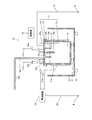
- FIG. 1 is a schematic cross-sectional view of an electrolysis apparatus according to an embodiment of the present invention.
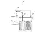
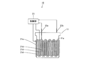
- FIG. 2 is a schematic view mainly of the outside of the electrolytic cell of the electrolytic apparatus of FIG.
- FIG. 3 is a flowchart showing the control operation of the heater and the blower by the control unit.
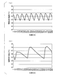
- FIG. 4 is a graph showing the results of the temperature of the electrolytic bath in Examples and Comparative Examples.
- FIG. 5 is a schematic view mainly of the outside of the electrolytic cell of the electrolysis apparatus according to another embodiment of the present invention.
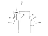
- FIG. 6 is a schematic view mainly outside the electrolytic cell of an electrolytic apparatus according to still another embodiment of the present invention.
- FIG. 1 is a schematic cross-sectional view of an electrolyzer according to an embodiment of the present invention.
- FIG. 2 is a schematic view mainly of the outside of the electrolytic cell of the electrolysis apparatus of FIG.
- the electrolysis device 10 includes an electrolytic cell 11.
- the electrolytic cell 11 includes an electrolytic cell main body 11a, an upper lid 11b, and an insulating member 11c.
- the electrolytic cell main body 11a and the upper lid body 11b are formed of a metal or an alloy such as Ni (nickel), monel, pure iron or stainless steel.
- the electrolytic cell main body 11a has a bottom part and four side parts, and has an opening at the top.
- the insulating member 11c is provided along the upper end surface of the side surface portion.
- the insulating member 11c is formed of an insulating material such as resin.
- An upper lid 11b is disposed on the insulating member 11c so as to close the opening of the electrolytic cell main body 11a. Thereby, the electrolytic cell main body 11a and the upper lid body 11b are electrically insulated from each other by the insulating member 11c.
- the electrolytic cell 11 high current power is handled. Moreover, it is necessary to prevent discharge in the electrolytic cell 11 due to static electricity. Therefore, the upper lid 11b of the electrolytic cell 11 is grounded to the ground E by the ground wire S1. Thereby, an electric shock or the like due to leakage from the electrolytic cell 11 is prevented.
- the electrolytic cell 11 is supported by a plurality of support members 31 made of an insulating material in a housing 32 made of a conductive material.
- the support member 31 is formed by, for example, bakelite.
- a wheel 33 made of an insulating material is attached to the bottom surface of the housing 32.
- the electrolytic cell 11 is electrically insulated from the housing 32, and the housing 32 is electrically insulated from the installation surface.
- an electrolytic bath 12 made of a KF-HF (potassium-hydrogen fluoride) mixed molten salt is formed.
- a cylindrical partition wall 13 is provided integrally with the upper lid body 11b so as to be partially immersed in the electrolytic bath 12.
- the partition wall 13 is made of, for example, Ni or Monel.
- an anode chamber 14 a is formed inside the partition wall 13, and a cathode chamber 14 b is formed outside the partition wall 13.
- the anode 15a is disposed so as to be immersed in the electrolytic bath 12 in the anode chamber 14a.
- a material of the anode 15a for example, a low polarizable carbon electrode is preferably used.
- a cathode 15b is formed on the inner surface of the electrolytic cell main body 11a. Hydrogen gas is mainly generated in the cathode chamber 14b.
- Ni is preferably used as the material of the cathode 15b.
- HF supply line 18a for supplying HF is connected to the upper lid 11b.
- the HF supply line 18a is covered with a temperature adjusting heater 18b. This prevents HF from being liquefied in the HF supply line 18a.
- the height of the electrolytic bath 12 is detected by a liquid level detector (not shown). When the height of the liquid level detected by the liquid level detection device becomes lower than a predetermined value, HF is supplied into the electrolytic cell 11 through the HF supply line 18a.
- the electrolysis apparatus 10 includes a control unit 23.
- the controller 23 applies a voltage between the anode 15a and the cathode 15b. Thereby, the electrolytic bath 12 in the electrolytic cell 11 is electrolyzed. Thereby, fluorine gas is mainly generated in the anode chamber 14a.
- the upper lid 11b is provided with gas discharge ports 16a and 16b.
- An exhaust pipe 17a is connected to the gas exhaust port 16a, and an exhaust pipe 17b is connected to the gas exhaust port 16b.
- the gas discharge port 16a communicates with the anode chamber 14a, and the gas discharge port 16b communicates with the cathode chamber 14b.
- the gas generated in the anode chamber 14a is discharged from the gas discharge port 16a through the exhaust pipe 17a, and the gas generated in the cathode chamber 14b is discharged from the gas discharge port 16b through the exhaust pipe 17b.
- the electrolytic cell 11 includes a heater 21a and a blower 21b.
- a sheathed heater is used as the heater 21a.
- the sheathed heater has a structure in which a heating wire is covered with an insulating film.
- the sheathed heater can obtain a heat capacity of an arbitrary size with a heating wire.
- the heater 21a is attached to meander on the outer surface of the side surface of the electrolytic cell main body 11a. Thereby, the contact area of the heater 21a and the electrolytic cell main body 11a becomes large. The heater 21a heats the electrolytic cell 11 by heat conduction.
- the blower 21 b is provided so as to be insulated from the electrolytic cell 11 and blows air to the electrolytic cell 11. Thereby, the air blower 21b cools the electrolytic cell 11 by air circulation in a state of being electrically insulated from the electrolytic cell 11.
- the heater 21a and the blower 21b operate with electric power supplied from the power supply device 21.
- the power supply device 21 is grounded to the ground E by a ground wire S2 in order to ensure safety.
- the heater 21a and the electrolytic cell 11 are electrically insulated from each other by the insulating coating provided in the sheathed heater that is the heater 21a. Moreover, the air blower 21b and the electrolytic cell 11 are electrically insulated by the air which is an insulator. In this case, even if the upper lid body 11b and the power supply device 21 are grounded to the ground E and a closed circuit is formed, current due to the potential difference in the electrolytic cell 11 does not flow to the metal portion of the electrolysis device. Thereby, the electric corrosion of the metal part of an electrolysis apparatus is prevented.
- the electrolysis apparatus 10 is provided with a temperature sensor 22a for detecting the temperature of the heater 21a and a temperature sensor 22b for detecting the temperature of the electrolytic bath 12 in the electrolytic cell main body 11a.
- the temperature sensors 22a and 22b are thermocouples.
- the control unit 23 controls the heater 21a and the blower 21b based on the temperature of the electrolytic cell 11 detected by the temperature sensor 22a and the temperature of the electrolytic bath 12 detected by the temperature sensor 22b.
- the electrolytic bath 12 in the electrolytic cell 11 is in a solid state at room temperature and atmospheric pressure. Therefore, in order to perform electrolysis of the electrolytic bath 12, the electrolytic bath 12 needs to be heated to 80 ° C. or higher and 90 ° C. or lower and dissolved in a liquid state.
- the control unit 23 turns on the heater 21a. Thereby, the temperature of the electrolytic cell 11 rises, and the temperature of the electrolytic bath 12 in the electrolytic cell 11 also rises. Until the electrolytic bath 12 is dissolved, the control unit 23 controls on and off of the heater 21a based on the temperature detected by the temperature sensor 22a.
- the temperature of the electrolytic cell 11 when the electrolytic bath 12 is dissolved (hereinafter referred to as the electrolytic cell temperature lower limit) is measured in advance.
- the control unit 23 When the temperature detected by the temperature sensor 22a is equal to or higher than a preset upper limit value (hereinafter referred to as an electrolytic cell temperature upper limit value), the control unit 23 is heated to prevent an excessive temperature rise in the electrolytic cell 11. The device 21a is turned off.
- a preset upper limit value hereinafter referred to as an electrolytic cell temperature upper limit value
- the temperature of the electrolytic bath 12 can be detected by the temperature sensor 22b.
- electrolysis is started, a larger amount of heat than the amount of heat lost due to natural heat dissipation is input to the electrolytic bath 12 due to generation of Joule heat or the like. Thereby, even in a state where the heater 21a is stopped, the temperature of the electrolytic bath 12 rises.
- the controller 23 controls the heater 21a and the blower 21b to be turned on and off based on the temperature detected by the temperature sensor 22b.
- FIG. 3 is a flowchart showing the control operation of the heater 21a and the blower 21b by the control unit 23.
- the upper limit of the temperature range of the electrolytic bath optimal for electrolysis is referred to as the target upper limit temperature
- the lower limit of the temperature range of the electrolytic bath optimal for electrolysis is referred to as the target lower limit temperature.
- the temperature at which the heater 21a is turned off and the blower 21b is turned on so that the temperature of the electrolytic bath does not exceed the target upper limit temperature is called a cooling start temperature, and heating is performed so that the temperature of the electrolytic bath does not fall below the target lower limit temperature.
- the temperature at which the device 21a is turned on and the blower 21b is turned off is called the heating start temperature.
- the cooling start temperature is set lower than the target upper limit temperature by a certain temperature (for example, 1 degree), and the heating start temperature is set higher than the target lower limit temperature by a certain temperature (for example, 1 degree).
- the control unit 23 determines whether or not the temperature of the electrolytic bath 12 detected by the temperature sensor 22b has increased to the cooling start temperature (step S1). If the temperature of the electrolytic bath 12 has not risen to the cooling start temperature, the control unit 23 waits until the temperature of the electrolytic bath 12 reaches the cooling start temperature. When the temperature of the electrolytic bath 12 rises to the cooling start temperature, the control unit 23 turns off the heater 21a (step S2) and turns on the blower 21b (step S3).
- the control unit 23 determines whether or not the temperature of the electrolytic bath 12 detected by the temperature sensor 22b has decreased to the heating start temperature (step S4). If the temperature of the electrolytic bath 12 has not decreased to the heating start temperature, the control unit 23 waits until the temperature of the electrolytic bath 12 reaches the heating start temperature. When the temperature of the electrolytic bath 12 falls to the heating start temperature, the control unit 23 turns on the heater 21a (step S5), turns off the blower 21b (step S6), and returns to the process of step S1.
- the temperature of the electrolytic bath 12 is maintained between the target upper limit temperature that is a constant temperature higher than the cooling start temperature and the target lower limit temperature that is a constant temperature lower than the heating start temperature.
- the electrolytic cell 11 is supported by the support member 31 so as to be electrically insulated from the housing 32. Further, the heater 21 a and the blower 21 b are electrically insulated from the electrolytic cell 11. In this state, the electrolytic cell 11 is heated by heat conduction from the heater 21a and cooled by air circulation from the blower 21b.
- heating of the electrolytic cell 11 is performed by heat conduction, and cooling of the electrolytic cell 11 is performed by air circulation.
- an insulating heat medium for heating and cooling the electrolytic cell 11 is not required. Therefore, the electrolytic cell 11 can be heated and cooled with a low cost and simple configuration.
- the electrolytic cell 11 is directly heated and cooled by heat conduction from the heater 21a and air flow from the blower 21b. Thereby, it becomes possible to control the temperature of the electrolytic bath 12 in the electrolytic cell 11 stably and with high accuracy.
- thermolysis apparatus 10 shown in FIGS. 1 and 2 based on the above embodiment.
- the electrolysis apparatus used in the comparative example has the same structure as the electrolysis apparatus 10 of FIGS. 1 and 2 except that the blower 21b is not attached.
- the heating start temperature and the cooling start temperature of the electrolytic bath 12 were set to 85 ° C. and 86 ° C., respectively.
- the heater 21a when the temperature of the electrolytic bath 12 detected by the temperature sensor 22b rises to 86 ° C., the heater 21a is turned off and the blower 21b is turned on, and the electrolytic bath 12 is forcibly cooled by blowing. .
- the heater 21a is turned on and the blower 21b is turned off to heat the electrolytic bath 12.
- the heater 21a when the temperature of the electrolytic bath 12 detected by the temperature sensor 22b rises to 86 ° C., the heater 21a is turned off and the electrolytic bath 12 is naturally cooled. When the temperature of the electrolytic bath 12 detected by the temperature sensor 22b is lowered to 85 ° C., the heater 21a is turned on and the electrolytic bath 12 is heated.
- FIG. 4A and FIG. 4B are diagrams respectively showing the results of the temperature of the electrolytic bath 12 in Examples and Comparative Examples.
- the horizontal axis indicates time, and the vertical axis indicates the temperature of the electrolytic bath 12.
- the temperature variation of the electrolytic bath 12 was controlled within a range of 2 degrees for a period of 889 minutes.
- the fluctuation of the temperature of the electrolytic bath 12 became 4 degrees or more during the period of 865 minutes.
- FIG. 5 is a schematic view mainly outside the electrolytic cell of an electrolysis apparatus according to another embodiment of the present invention.
- the plurality of infrared heating devices 21 c are provided so as to be separated from the electrolytic cell 11 and radiate infrared rays to the electrolytic cell 11. Thereby, the plurality of infrared heating devices 21 c heat the electrolytic cell 11 by thermal radiation while being electrically insulated from the electrolytic cell 11.
- FIG. 6 is a schematic view mainly outside the electrolytic cell of the electrolysis apparatus according to still another embodiment of the present invention.
- the electrolyzer 10 of FIG. 6 differs from the electrolyzer 10 of FIGS. 1 and 2 in that a plurality of cooling bodies 21d are in contact with the outer surface of the side surface portion of the electrolytic cell main body 11a in place of the blower 21b, and are dispersed. It is a point attached to.
- the cooling body 21d has a structure in which a Peltier element is insulated by a ceramic material and an insulating coating. Accordingly, the plurality of cooling bodies 21 d cool the electrolytic cell 11 by performing an endothermic operation while being electrically insulated from the electrolytic cell 11.
- a plurality of infrared heating devices 21c may be provided instead of the heater 21a of FIGS. 1 and 2, and a plurality of cooling bodies 21d may be provided instead of the blower 21b.
- the heater 21a and the infrared heating device 21c are examples of a heat source and a heating unit
- the blower 21b and the cooling body 21d are examples of a heat radiation source and a cooling unit
- the heating wire of the sheathed heater is an example of a heating element.
- 21a is an example of a heater
- a Peltier element is an example of a cooling element
- an anode chamber 14a is an example of a first chamber
- a cathode chamber 14b is an example of a second chamber
- an anode 15a is an example of a first electrode.
- the cathode 15b is an example of the second electrode
- the control unit 23 is an example of the control unit
- the temperature sensor 22b is an example of the detection unit.
- the present invention can be effectively used for an electrolyzer such as a gas generator.
Landscapes
- Chemical & Material Sciences (AREA)
- Engineering & Computer Science (AREA)
- Chemical Kinetics & Catalysis (AREA)
- Electrochemistry (AREA)
- Materials Engineering (AREA)
- Metallurgy (AREA)
- Organic Chemistry (AREA)
- Automation & Control Theory (AREA)
- Inorganic Chemistry (AREA)
- Electrolytic Production Of Non-Metals, Compounds, Apparatuses Therefor (AREA)
Priority Applications (3)
| Application Number | Priority Date | Filing Date | Title |
|---|---|---|---|
| US13/394,482 US20120160667A1 (en) | 2009-09-07 | 2010-09-02 | Electrolytic device |
| EP10813517A EP2476783A4 (en) | 2009-09-07 | 2010-09-02 | ELECTROLYSIS DEVICE |
| CN2010800397675A CN102482790A (zh) | 2009-09-07 | 2010-09-02 | 电解装置 |
Applications Claiming Priority (2)
| Application Number | Priority Date | Filing Date | Title |
|---|---|---|---|
| JP2009-205491 | 2009-09-07 | ||
| JP2009205491A JP2011058015A (ja) | 2009-09-07 | 2009-09-07 | 電解装置 |
Publications (1)
| Publication Number | Publication Date |
|---|---|
| WO2011027566A1 true WO2011027566A1 (ja) | 2011-03-10 |
Family
ID=43649121
Family Applications (1)
| Application Number | Title | Priority Date | Filing Date |
|---|---|---|---|
| PCT/JP2010/005419 WO2011027566A1 (ja) | 2009-09-07 | 2010-09-02 | 電解装置 |
Country Status (6)
| Country | Link |
|---|---|
| US (1) | US20120160667A1 (zh) |
| EP (1) | EP2476783A4 (zh) |
| JP (1) | JP2011058015A (zh) |
| KR (1) | KR20120083311A (zh) |
| CN (1) | CN102482790A (zh) |
| WO (1) | WO2011027566A1 (zh) |
Cited By (1)
| Publication number | Priority date | Publication date | Assignee | Title |
|---|---|---|---|---|
| JP2014506630A (ja) * | 2011-03-14 | 2014-03-17 | キム,ギョンス | オープンセル方式の次亜塩素酸ナトリウム製造装置 |
Families Citing this family (6)
| Publication number | Priority date | Publication date | Assignee | Title |
|---|---|---|---|---|
| JP5824256B2 (ja) * | 2011-06-29 | 2015-11-25 | 東洋炭素株式会社 | 電解装置 |
| WO2013054433A1 (ja) * | 2011-10-14 | 2013-04-18 | 株式会社エスマック | 水素-酸素ガス発生装置 |
| JP5906742B2 (ja) * | 2012-01-05 | 2016-04-20 | セントラル硝子株式会社 | フッ素ガス生成装置 |
| WO2014021794A1 (en) * | 2012-08-01 | 2014-02-06 | Sukij Tridsadeerak | Hpc2 hydrogen separation tank with liquid cooling system |
| CN108950594B (zh) * | 2018-09-29 | 2020-02-07 | 青海铜业有限责任公司 | 电解槽和电解槽系统 |
| US20230052850A1 (en) * | 2019-12-10 | 2023-02-16 | Sunfire Gmbh | Solid oxide cell assembly |
Citations (6)
| Publication number | Priority date | Publication date | Assignee | Title |
|---|---|---|---|---|
| JP2000042555A (ja) * | 1998-08-04 | 2000-02-15 | Sanyo Electric Co Ltd | 電解水冷却装置 |
| JP2004089702A (ja) * | 2002-07-26 | 2004-03-25 | Heraeus Kulzer Gmbh | 補綴の金属製の歯科用成形部材を電気めっきにより析出するための装置 |
| JP2004204347A (ja) * | 2002-12-21 | 2004-07-22 | Sang Nam Kim | ブラウンガス発生装置 |
| JP2004244724A (ja) | 2003-01-22 | 2004-09-02 | Toyo Tanso Kk | 溶融塩電解装置 |
| JP2005048290A (ja) * | 2003-01-22 | 2005-02-24 | Toyo Tanso Kk | 溶融塩電解装置 |
| JP2007046110A (ja) * | 2005-08-10 | 2007-02-22 | Honda Motor Co Ltd | 水電解システムの運転方法 |
Family Cites Families (7)
| Publication number | Priority date | Publication date | Assignee | Title |
|---|---|---|---|---|
| GB812817A (en) * | 1954-05-21 | 1959-04-29 | Solar Aircraft Co | Electrolytic production of titanium |
| US2841544A (en) * | 1956-04-24 | 1958-07-01 | Minnesota Mining & Mfg | Process for the production of fluorinecontaining compounds |
| US3645879A (en) * | 1970-06-08 | 1972-02-29 | Haskett Barry F | Construction of electrolytic cell |
| IT1199898B (it) * | 1985-07-22 | 1989-01-05 | Ginatta Marco Elettrochim | Impianto per la produzione elettrolitica in bagno di sali fusi di metalli reattivi |
| JPH0373899A (ja) * | 1989-08-15 | 1991-03-28 | Toshiba Corp | 溶融塩電解精製装置 |
| CN1327032C (zh) * | 2001-12-17 | 2007-07-18 | 东洋炭素株式会社 | F2气体发生装置与f2气体发生方法及f2气体 |
| TWI322198B (en) * | 2003-01-22 | 2010-03-21 | Toyo Tanso Co | Electrolytic apparatus for molten salt |
-
2009
- 2009-09-07 JP JP2009205491A patent/JP2011058015A/ja active Pending
-
2010
- 2010-09-02 WO PCT/JP2010/005419 patent/WO2011027566A1/ja active Application Filing
- 2010-09-02 CN CN2010800397675A patent/CN102482790A/zh active Pending
- 2010-09-02 EP EP10813517A patent/EP2476783A4/en not_active Withdrawn
- 2010-09-02 US US13/394,482 patent/US20120160667A1/en not_active Abandoned
- 2010-09-02 KR KR1020127006048A patent/KR20120083311A/ko not_active Application Discontinuation
Patent Citations (6)
| Publication number | Priority date | Publication date | Assignee | Title |
|---|---|---|---|---|
| JP2000042555A (ja) * | 1998-08-04 | 2000-02-15 | Sanyo Electric Co Ltd | 電解水冷却装置 |
| JP2004089702A (ja) * | 2002-07-26 | 2004-03-25 | Heraeus Kulzer Gmbh | 補綴の金属製の歯科用成形部材を電気めっきにより析出するための装置 |
| JP2004204347A (ja) * | 2002-12-21 | 2004-07-22 | Sang Nam Kim | ブラウンガス発生装置 |
| JP2004244724A (ja) | 2003-01-22 | 2004-09-02 | Toyo Tanso Kk | 溶融塩電解装置 |
| JP2005048290A (ja) * | 2003-01-22 | 2005-02-24 | Toyo Tanso Kk | 溶融塩電解装置 |
| JP2007046110A (ja) * | 2005-08-10 | 2007-02-22 | Honda Motor Co Ltd | 水電解システムの運転方法 |
Non-Patent Citations (1)
| Title |
|---|
| See also references of EP2476783A4 |
Cited By (1)
| Publication number | Priority date | Publication date | Assignee | Title |
|---|---|---|---|---|
| JP2014506630A (ja) * | 2011-03-14 | 2014-03-17 | キム,ギョンス | オープンセル方式の次亜塩素酸ナトリウム製造装置 |
Also Published As
| Publication number | Publication date |
|---|---|
| EP2476783A4 (en) | 2012-10-31 |
| US20120160667A1 (en) | 2012-06-28 |
| KR20120083311A (ko) | 2012-07-25 |
| CN102482790A (zh) | 2012-05-30 |
| EP2476783A1 (en) | 2012-07-18 |
| JP2011058015A (ja) | 2011-03-24 |
Similar Documents
| Publication | Publication Date | Title |
|---|---|---|
| WO2011027566A1 (ja) | 電解装置 | |
| JP5852774B2 (ja) | 液体試料加熱気化装置 | |
| US20180306468A1 (en) | Heat generating system | |
| JP2011058015A5 (zh) | ||
| JP3725145B2 (ja) | 溶融塩電解浴の制御装置及びその制御方法 | |
| KR101363359B1 (ko) | 스테인레스 스틸의 전기 저항을 갖는 양극화된 알루미늄의 방사 패널 | |
| KR20100130447A (ko) | 전기 아크를 발생시키는 열교환 반응로를 구비하는 전기보일러 및 그 작동 방법 | |
| JP6224366B2 (ja) | 支持部材及び基板処理装置 | |
| TWI721607B (zh) | 氟氣製造裝置 | |
| Slovetskii et al. | Parameters of an electric discharge in electrolytes and physicochemical processes in an electrolyte plasma | |
| JP2011133426A (ja) | 静電容量式レベル計 | |
| JP7409771B2 (ja) | 液体を蒸気に変えるための装置、及び加熱電力を制御するための関連する方法 | |
| JP3573058B2 (ja) | 温度調整装置 | |
| JP4083672B2 (ja) | 絶縁支持部材および電解槽 | |
| JP5132959B2 (ja) | 真空処理装置 | |
| KR101261399B1 (ko) | 히터시스템의 온도 제어시스템 및 이를 이용한 온도 제어방법 | |
| US20130118184A1 (en) | Cooled charged particle systems and methods | |
| JP4576238B2 (ja) | 電子部品装置、及びそれを用いた直流高電圧電源装置 | |
| JP2008081786A (ja) | 電解装置の電極構造、電解装置、および金属精錬方法 | |
| JP4460939B2 (ja) | 基板加熱ヒータ | |
| JPH0836983A (ja) | イオン源 | |
| RU2286033C1 (ru) | Плазмотрон с жидким электролитным катодом | |
| RU2258329C1 (ru) | Электродный узел | |
| ITAN20010005A1 (it) | Mezzi per la protezione anticorrosione di serbatoi metallici contenenti liquidi da riscaldare, in particolare di scaldabagni | |
| JP5217635B2 (ja) | 真空成膜装置 |
Legal Events
| Date | Code | Title | Description |
|---|---|---|---|
| WWE | Wipo information: entry into national phase |
Ref document number: 201080039767.5 Country of ref document: CN |
|
| 121 | Ep: the epo has been informed by wipo that ep was designated in this application |
Ref document number: 10813517 Country of ref document: EP Kind code of ref document: A1 |
|
| WWE | Wipo information: entry into national phase |
Ref document number: 13394482 Country of ref document: US |
|
| ENP | Entry into the national phase |
Ref document number: 20127006048 Country of ref document: KR Kind code of ref document: A |
|
| NENP | Non-entry into the national phase |
Ref country code: DE |
|
| WWE | Wipo information: entry into national phase |
Ref document number: 2010813517 Country of ref document: EP |